Product: MULTI TERRAIN LOADER
Model: 267 MULTI TERRAIN LOADER CMP
Configuration: 267 277 Multi Terrain Loader CMP00001-UP (MACHINE) POWERED BY 3034 Engine
Disassembly and Assembly
267, 277 and 287 Multi Terrain Loaders Engine Supplement
Media Number -RENR4814-01
Publication Date -01/12/2003
Air Cleaner - Remove and Install
SMCS - 1051-010
Removal Procedure
267 Multi Terrain Loader
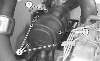
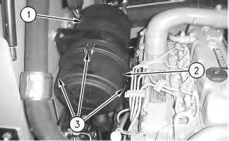
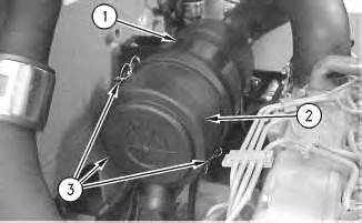
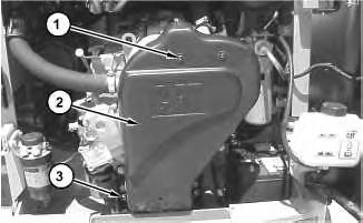
Illustration 1
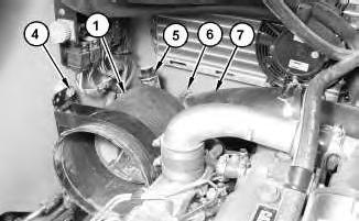
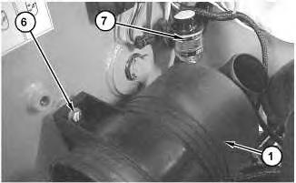
1. Release clamps (3). Remove air cleaner cover (2) from air cleaner housing (1) .
Date Updated -04/12/2003
i01984677
2. Remove the primary air filter and the secondary air filter from inside air cleaner housing (1) .
2
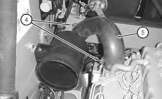
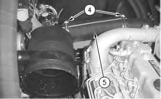
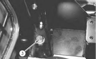
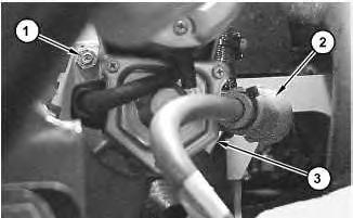
3. Loosen clamps (4). Disconnect hose (5) .
3
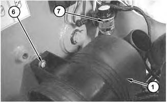
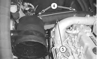
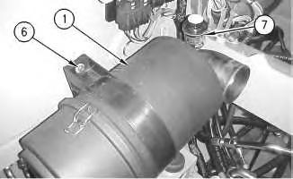
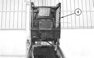
4. Remove bolts (6). Remove air cleaner housing (1) .
5. Remove service indicator (7) . Removal Procedure
277 Multi Terrain Loader
Illustration
g01033182
Illustration
g01033181
4
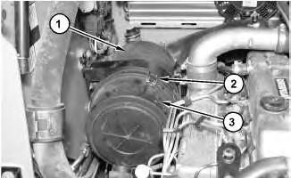
1. Release clamps (3). Remove air cleaner cover (2) from air cleaner housing (1) .
2. Remove the primary air filter and the secondary air filter from inside air cleaner housing (1) .
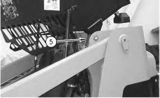
5
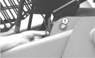
3. Loosen clamps (4). Disconnect hose (5) .
Illustration
g00766044
Illustration
g00766054
Illustration 6
g00779924
4. Remove bolts (6). Remove air cleaner housing (1) .
5. Remove service indicator (7) .
Removal Procedure
287 Multi Terrain Loader
Illustration 7
g01028489
1. Release clamps (2). Remove air cleaner cover (3) from air cleaner housing (1) .
2. Remove the primary air filter and the secondary air filter from inside air cleaner housing (1) .
This is the sample of the manual
Click on the download link for complete Manual
Illustration 8
3. Loosen clamps (6) and disconnect hose (7) .
4. Remove nuts(4) and the spacers.
5. Remove service indicator (5) .
6. Remove air cleaner housing (1) .
Installation
Procedure
267 Multi Terrain Loader
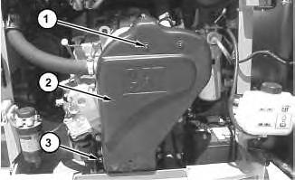
Illustration 9
g01033181
1. Apply Tooling (A) to the threads of service indicator (7). Install service indicator (7) into air cleaner housing (1). Tighten the service indicator until the service indicator makes contact with the base of the fitting. Tighten the service indicator by another 1/4 turn.
2. Place air cleaner housing (1) into position. Install bolts(6). Tighten bolts (6) to a torque of 19 ± 2 N·m (14 ± 1 lb ft).
Illustration 10
g01033182
3. Connect hose (5). Tighten clamps (4) to a torque of 4.5 ± 1 N·m (40 ±9 lb in).
Illustration 11
g00766191
4. Install the primary air filter and the secondary air filter into air cleaner housing (1) .
5. Install air cleaner cover (2) and secure clamps(3) .
Installation Procedure
277 Multi Terrain Loader
Illustration 12
1. Apply Tooling (A) to the threads of service indicator (7). Install service indicator (7) into air cleaner housing (1). Tighten the service indicator until the service indicator makes contact with the base of the fitting. Tighten the service indicator by another 1/4 turn.
2. Place air cleaner housing (1) into position. Install bolts(6). Tighten bolts (6) to a torque of 19 ± 2 N·m (14 ± 1 lb ft).
Illustration 13
3. Connect hose (5). Tighten clamps (4) to a torque of 4.5 ± 1 N·m (40 ±9 lb in).
Illustration 14 g00766044
4. Install the primary air filter and the secondary air filter into air cleaner housing (1) .
5. Install air cleaner cover (2) and secure clamps(3) .
Installation Procedure
287 Multi Terrain Loader
Illustration 15
1. Apply Tooling (A) to the threads of service indicator (5). Install service indicator (5) into air cleaner housing (1). Tighten the service indicator until the service indicator makes contact with the base of the fitting. Tighten the service indicator by another 1/4 turn.
2. Place air cleaner housing (1) into position. Install the spacers and bolts (4). Tighten bolts(4) to a torque of 19 ± 2 N·m (14 ±1 lb ft).
3. Connect hose (7). Tighten clamps (6) to a torque of 4.5 ± 1 N·m (40 ±9 lb in).
Illustration 16
g01028489
4. Install the primary air filter and the secondary air filter into air cleaner housing (1) .
5. Install air cleaner cover (3) and secure clamps(2) .
g01028490
Product: MULTI TERRAIN LOADER
Model: 267 MULTI TERRAIN LOADER CMP
Configuration: 267 277 Multi Terrain Loader CMP00001-UP (MACHINE) POWERED BY 3034 Engine
Disassembly and Assembly
267, 277 and 287 Multi Terrain Loaders Engine Supplement
Media Number -RENR4814-01
Publication Date -01/12/2003
Date Updated -04/12/2003
Alternator - Remove and Install - Without Air Conditioning
SMCS - 1405-010
Removal Procedure
i01990559
1. Disconnect the battery. Refer to Disassembly and Assembly, "Battery and Battery Cable - Seperate and Connect".
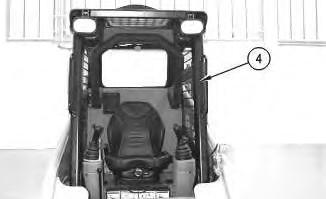
Illustration 1
2. Remove screws (1) and bolts (3) .
3. Remove cover (2) .
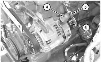
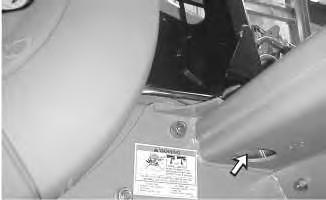
Illustration 2
4. Remove cable strap (5). Raise rubber boot (4).
5. Disconnect harnessassembly (6) .
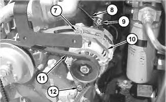
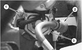
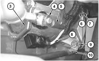
Illustration 3
6. Remove nut (9). Disconnect cable assembly (8) .
7. Loosen bolts (7) and (12) .
8. Slide alternator (10) toward the engine.
9. Remove V-belt (11) from alternator (10) .
10. Remove bolts (7) and (12) .
11. Remove alternator (10) .
Installation Procedure
g01033323
g01033324
4
1. Place alternator (10) in position.
2. Install bolts (7) and (12). Do not tighten bolts (7) and (12) at this time.
Note: When you install the alternator, ensure that the alternator pulley is in alignment with the crankshaft pulley within 2.4 mm (0.09 inch).
3. Install V-belt (11) onto alternator (10) .
4. Slide alternator (10) away from the engine in order to tighten V-belt (11) .
Note: Refer to the Operation and Maintenance Manual, "Belts - Inspect/Adjust/Replace" for the correct procedure.
5. Tighten bolt (7) to a torque of 12 N·m (9 lb ft).
6. Tighten bolt (12) to a torque of 24 N·m (18 lb ft).
7. Connect cable assembly (8). Install nut (9) .
Illustration
Illustration 5
8. Connect harness assembly (6) .
9. Install rubber boot (4). Install cable strap (5) .
Illustration 6
10. Place cover (2) in position.
11. Install bolts (3). Tighten bolts(3) to a torque of 15 ±3 N·m (11 ± 2 lb ft).
12. Install screws (1). Tighten screws (1) to a torque of 6 ± 1 N·m (53 ± 9 lb in).
13. Connect the battery cables. Refer to Disassembly and Assembly, "Battery and Battery Cable - Seperate and Connect".
1993 - 2019 Caterpillar Inc.
13 10:22:17 UTC+0530 2019
Product: MULTI TERRAIN LOADER
Model: 267 MULTI TERRAIN LOADER CMP
Configuration: 267 277 Multi Terrain Loader CMP00001-UP (MACHINE) POWERED BY 3034 Engine
Disassembly and Assembly
267, 277 and 287 Multi Terrain Loaders Engine Supplement
Media Number -RENR4814-01
Publication Date -01/12/2003
Battery and Battery Cable - Separate and Connect
SMCS - 1401-029
Separation Procedure
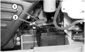
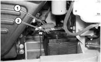
Illustration 1
Date Updated -04/12/2003
i01988120
g01029662
1. Raise the cover on the negative terminal of the battery. Disconnect negative terminal (2) of the battery. Place a protective cover on the negative terminal of the battery.
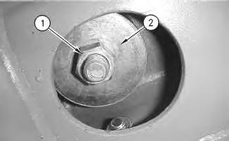
2. Raise the cover on the positive terminal of the battery. Disconnect positive terminal (1) of the battery. Place a protective cover on the positive terminal of the battery.
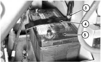
2
3. Remove bolts (3). Remove bracket (4) .
4. Remove battery (5) .
Connection Procedure
3
1. Install battery (5) .
Note: Both battery terminals must be next to the engine.
2. Install bracket (4). Install bolts (3) .
Illustration
g01029663
Illustration
g01029663
4
3. Remove the protective cover from the positive terminal of the battery. Connect positive terminal (1) Lower the cover on the positive terminal of the battery.
4. Remove the protective cover from the negative terminal of the battery. Connect negative terminal (2). Lower the cover on the negative terminal of the battery. Copyright 1993 - 2019 Caterpillar Inc.
Rights Reserved. Private Network For SIS Licensees.
Product: MULTI TERRAIN LOADER
Model: 267 MULTI TERRAIN LOADER CMP
Configuration: 267 277 Multi Terrain Loader CMP00001-UP (MACHINE) POWERED BY 3034 Engine
Disassembly and Assembly
267, 277 and 287 Multi Terrain Loaders Engine Supplement
Media Number -RENR4814-01
Publication Date -01/12/2003
Date Updated -04/12/2003
Cab - Tilt
SMCS - 7301-084
Procedure to Tilt the Cab
Start By:
A. Release the hydraulic system pressure. Refer to Disassembly and Assembly, "Hydraulic System Pressure - Release".
Do not go beneath cab unlesscab isempty and support lever is engaged.
Failure to follow the instructionsor heed the warnings could result in injury or death.
Note: Empty the water tank (if equipped) before you tilt the cab.
i01715326
Illustration 1
Illustration 2
g00597525
1. Remove nut (1) and large washer (2) from the inside of the cab.
Illustration 3
g00597551
g00601508
2. Remove bolt (3) .
3. Repeat Steps 1 and 2 on the opposite side of the cab.
Illustration 4
4. Raise cab (4) .
Illustration 5
g00597554
g00601451
Illustration 6 g00563598
.
Lower Procedure
7 g00601456
5. Engage cab support lever (5)
Illustration
Illustration 8 g00563674
Illustration 9 g00601528
1. Tilt the cab upward.
2. Disengage cab support lever (5) .
3. Lower cab (4) .
10
11
12
Illustration
g00597551
4. Install bolt (3) .
Illustration
g00601508
Illustration
g00597525
Note: Ensure that the large washer isbetween the nut and the rubber mounting.
5. Install large washer (2) and nut (1) from the inside of the cab. Tighten the nuts to a torque of 125 ± 10 N·m (92 ± 7 lb ft).
6. Repeat Steps 4 and 5 on the opposite side of the cab. Copyright 1993 - 2019 Caterpillar Inc.
Product: MULTI TERRAIN LOADER
Model: 267 MULTI TERRAIN LOADER CMP
Configuration: 267 277 Multi Terrain Loader CMP00001-UP (MACHINE) POWERED BY 3034 Engine
Disassembly and Assembly
267, 277 and 287 Multi Terrain Loaders Engine Supplement
Media Number -RENR4814-01
Publication Date -01/12/2003
Date Updated -04/12/2003
i01990623
Electric Starting Motor - Remove and Install - 267 and 277 Multi Terrain Loaders
SMCS - 1453-010
S/N- CMP1-UP
S/N- CNC1-UP
Removal procedure
Accidental machine starting can cause injury or death to personnel working onthe machine.
To avoid accidental machine starting, turn the battery disconnect switch to the OFF position and remove the key. If the machine isnot equippedwith a battery disconnect switch, disconnect the battery cables from the battery and tape the battery clamps.
Place a do not operate tag at the battery disconnect switch location to inform personnel that the machine is being worked on.
1. Disconnect the battery cables. Refer to Disassembly and Assembly, "Battery and Battery CableSeperate and Connect".
Illustration 1
Remove nut (1) .
3. Slide boot (2) away from the positive terminal on electric starting motor (3) .
Illustration 2
4. Remove nut (4). Disconnect positive cable (5) from electric starting motor (3) .
5. Remove nut (9). Disconnect negative cable (10) from electric starting motor (3) .
6. Disconnect wire (8) .
7. Support electric starting motor (3) .
8. Remove nut (6) and clip (7) .
9. Remove electric starting motor (3) .
Installation Procedure
g01033410
2.
g01033411
Accidental machine starting can cause injury or death to personnel working onthe machine.
To avoid accidental machine starting, turn the battery disconnect switch to the OFF position and remove the key. If the machine isnot equippedwith a battery disconnect switch, disconnect the battery cables from the battery and tape the battery clamps.
Place a do not operate tag at the battery disconnect switch location to inform personnel that the machine is being worked on.
3
1. Place electric starting motor (3) in position.
2. Install clip (7) and nut (6). Tighten nut (6) to a torque of 50 ± 6 N·m (37 ± 4 lb ft).
3. Connect negative cable (10) to electric starting motor (3) and install nut (9). Tighten nut (9) to a torque of 50 ± 6 N·m (37 ± 4 lb ft).
4. Connect wire (8) .
5. Connect positive cable (5) to electric starting motor (3) and install nut (4) .
Illustration
g01033411
This is the sample of the manual
Click on the download link for complete Manual
Illustration 4
6. Slide boot (2) over the positive terminal of electric starting motor (3) .
7. Install nut (1). Tighten nut (1) to a torque of 50 ± 6 N·m (37 ± 4 lb ft).
8. Connect the battery cables. Refer to Disassembly and Assembly, "Battery and Battery Cable - Seperate and Connect".
9. Start the engine and check for proper operation of the electric starting motor. Copyright 1993 - 2019 Caterpillar Inc. All Rights Reserved. Private Network For SIS Licensees.