

Previous Screen
Product: MULTI TERRAIN LOADER
Model: 257 MULTI TERRAIN LOADER CMM
Configuration: 247 257 Multi Terrain Loader CMM00001-UP (MACHINE) POWERED BY 3034 Engine
Disassembly and Assembly
247 and 257 Multi Terrain Loaders3034 Engine Supplement Media
Air Cleaner - Remove and Install
Removal Procedure
i01797716
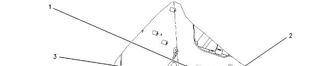
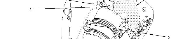
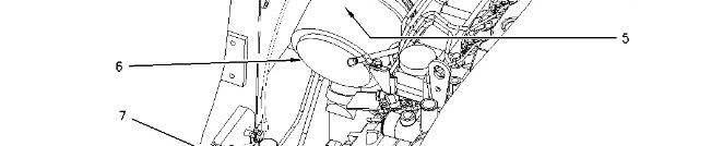

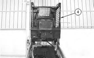
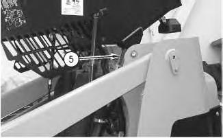
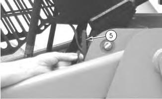
Illustration 1
1. Remove clamps (1). Remove hose (2). Disconnect hose (3) at each end. Removefitting (4). Remove bolts (5). Remove air cleaner (6).Remove bolts (7). Remove service indicator (8) .
Installation Procedure
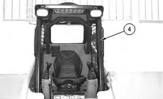
Illustration 2
1. Install service indicator (8).Install bolts (7).Torque bolts (7) to 1.7 ± .25 N·m (15 ±2 lb in). Position air cleaner (6). Install bolts (5). Apply Tooling (A) to fitting (4). Install fitting (4). Connect hose (3) at each end. Install hose (2). Installclamps (1). Torque clamps (1) to 4.5 ± .5 N·m (40 ± 4 lb in). Copyright 1993 - 2020 Caterpillar Inc.
Previous Screen
Product: MULTI TERRAIN LOADER
Model: 257 MULTI TERRAIN LOADER CMM
Configuration: 247 257 Multi Terrain Loader CMM00001-UP (MACHINE) POWERED BY 3034 Engine
Disassembly and Assembly
247 and 257 Multi Terrain Loaders3034 Engine Supplement
Media Number -RENR4851-00
Publication Date -01/09/2002
Alternator - Remove and Install
SMCS- 1405-010
Removal Procedure
Start By:
Date Updated -15/10/2002
i01797581
A. Disconnect thebattery. Refer to Disassembly and Assembly, "Battery and Battery Cable - Seperate and Connect".
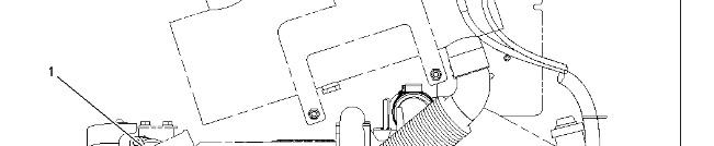
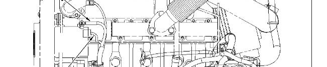
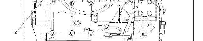
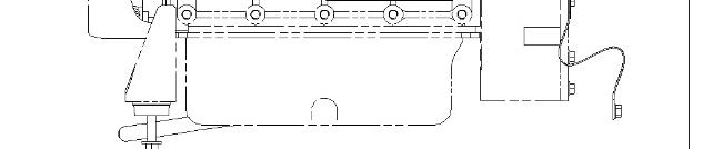
Illustration 1
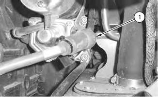
1. Disconnect harness assembly (1). Disconnect
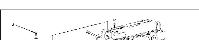
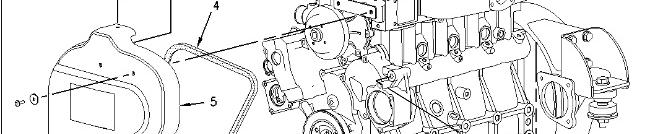
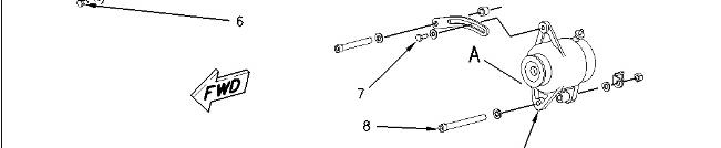
Illustration 2
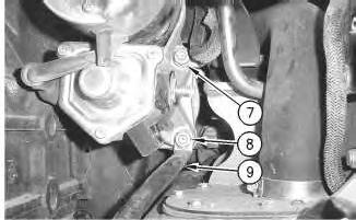
2. Remove bolts (3). Removebolts (6). Removecover (5). Loosen bolts (7) and (8).Remove belt (4). Remove bolts (7) and (8). Remove alternator (9) .
Installation Procedure
This is the sample of the manual
Click on the download link for complete Manual
Illustration 3
1. Placealternator (9) in position.
2. Install bolts (7) and (8). Do not tighten bolts (7) and (8) atthis time.
Note: When you install the alternator,ensure that thealternator pulley is in alignment with the crankshaftpulley within 2.4 mm (0.09 inch).
3. Install belt (4). Refer to the Operation and Maintenance Manual, SEBU7468, "BeltsInspect/Adjust/Replace" for the correct procedure.
4. Torque bolt (7) to 15 ± 3 N·m (11 ±2 lb ft).
5. Torque bolt (8) to 30 ± 7 N·m (22 ±5 lb ft).
6. Placecover (5) in position.
7. Torque washers and bolts (6) to 15 ± 3 N·m (11 ± 2 lb ft).
8. Install washers and bolts (3) to a torque of 6 ± 1 N·m (53 ±9 lb in).
Illustration 4
9. Connect harness assembly (2). Connect harness assembly (1). Torque the nut to 8 ± 2 N·m (71 ± 18 lb in).
EndBy: Connect the battery. Refer to Disassembly and Assembly, "Battery and Battery Cable - Seperate and Connect".
Copyright 1993 - 2020 Caterpillar Inc. All Rights Reserved. Private Network For SIS Licensees. Fri Apr 17 11:11:24 UTC+0530 2020

PreviousScreen
Product: MULTI TERRAIN LOADER
Model: 257 MULTI TERRAIN LOADER CMM
Configuration: 247 257 Multi Terrain Loader CMM00001-UP (MACHINE) POWERED BY 3034 Engine
Disassembly and Assembly
247 and 257 Multi Terrain Loaders3034 Engine Supplement
Media Number -RENR4851-00 Publication Date -01/09/2002 Date Updated -15/10/2002
Battery and Battery Cable - Separate and Connect
SMCS - 1401-029
Separation Procedure
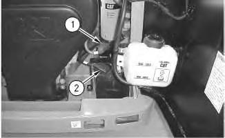
1. Raise the cover on the negative terminal of the battery. Disconnect negative terminal (2) of the battery. Place a protective cover on the negative terminal of the battery.
2. Raise the cover on the positive terminal of the battery. Disconnect positive terminal (1) of the battery. Place a protective cover on the positive terminal of the battery.
2
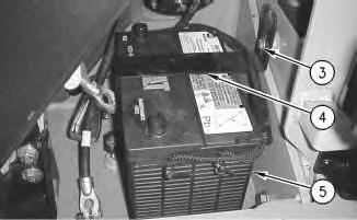
3. Remove bolts (3). Remove bracket (4) .
4. Remove battery (5) .
Connection Procedure
Illustration 3
1. Install battery (5) .
Note: Both battery terminals must be next to the engine.
2. Install bracket (4). Install bolts (3) .

3. Remove the protective cover from the positive terminal of the battery. Connect positive terminal (1). Lower the cover on the positive terminal of the battery.
4. Remove the protective cover from the negative terminal of the battery. Connect negative terminal (2). Lower the cover on the negative terminal of the battery. Copyright 1993 - 2020 Caterpillar Inc.
Rights Reserved.
SIS
PreviousScreen
Product: MULTI TERRAIN LOADER
Model: 257 MULTI TERRAIN LOADER CMM
Configuration: 247 257 Multi Terrain Loader CMM00001-UP (MACHINE) POWERED BY 3034 Engine
Disassembly and Assembly
247 and 257 Multi Terrain Loaders3034 Engine Supplement Media
Cab - Tilt
SMCS - 7301-084
Procedure to Tilt the Cab
Start By:
A. Release the hydraulic system pressure. Refer to Disassembly and Assembly, "Hydraulic System Pressure - Release".
Do not go beneath cab unlesscabisempty and support lever is engaged.
Failure to follow the instructionsor heed the warnings could result in injury or death.
Note: Empty the water tank (if equipped) before you tilt the cab.

Illustration 1
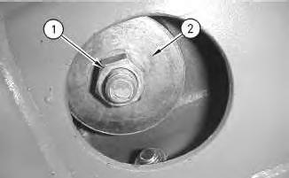
Illustration 2
g00597525
1. Remove nut (1) and large washer (2) from the inside of the cab.
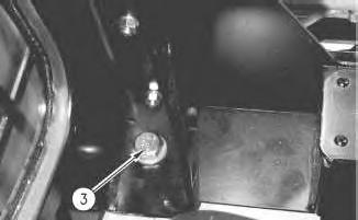
Illustration 3
2. Remove bolt (3) .
g00597551
3. Repeat Steps 1 and 2 on the opposite side of the cab.


6 g00563598
Lower Procedure
7 g00601456


8 g00563674
9
10
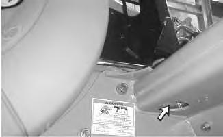
Illustration 11
Illustration 12
Note: Ensure that the large washer isbetween the nut and the rubber mounting.
5. Install large washer (2) and nut (1) from the inside of the cab. Tighten the nuts to a torque of 125 ± 10 N·m (92 ± 7 lb ft).
6. Repeat Steps 4 and 5 on the opposite side of the cab.
1993 - 2020 Caterpillar Inc.
PreviousScreen
Product: MULTI TERRAIN LOADER
Model: 257 MULTI TERRAIN LOADER CMM
Configuration: 247 257 Multi Terrain Loader CMM00001-UP (MACHINE) POWERED BY 3034 Engine
Disassembly and Assembly
247 and 257 Multi Terrain Loaders3034 Engine Supplement
Electric Starting Motor - Remove and Install
SMCS - 1453-010
Removal procedure
Start By:
A. Disconnect the battery. Refer to Disassembly and Assembly, "Battery and Battery CableSeperate and Connect".
Accidental machine starting can cause injury or death to personnel working onthe machine.
To avoid accidental machine starting, turn the battery disconnect switch to the OFF position and remove the key. If the machine is not equippedwith a battery disconnect switch, disconnect the battery cables from the battery and tape the battery clamps.
Place a do not operate tag at the battery disconnect switch location to inform personnel that the machine is being worked on.
1
1. Slide cover (1) in order to expose the connection.
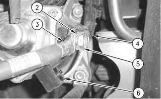
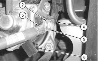
Illustration 2
2. Remove nut (5). Remove harness assembly (4). Remove lock washer (2). Remove cable assembly (3). Remove the screw and harness assembly (6) .
3
3. Remove the nut and washer (8). Remove cable assembly (9). Remove the nut, the washer, and clip (7) .
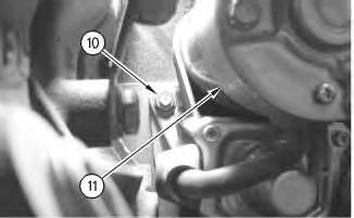
Illustration 4
4. Remove the nut and washer (10) .
5. Remove electric starting motor (11) .
Installation Procedure
Accidental machine starting can cause injury or death to personnel working onthe machine.
To avoid accidental machine starting, turn the battery disconnect switch to the OFF position and remove the key. If the machine is not equippedwith a battery disconnect switch, disconnect the battery cables from the battery and tape the battery clamps.
Place a do not operate tag at the battery disconnect switch location to inform personnel that the machine is being worked on.
5
1. Install electric starting motor (11). Install the nut and washer (10) .
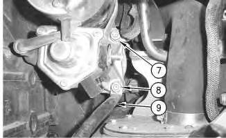
Illustration 6
2. Install the nut, the washer, and clip (7). Install cable assembly (9). Install the nut and washer (8) .
7
3. Install the screw and harnessassembly (6). Torque the screwto 3.6 ±1 N·m (32 ± 9 lb in). Install cable assembly (3). Install lock washer (2). Install harness assembly (4). Install nut (5). Torque nut (5) to 21 ±4 N·m (15 ± 3 lb ft).
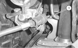
Illustration 8 g00890215
4. Slide cover (1) in order to protect the connection.
End By: Connect the battery. Refer to Disassembly and Assembly, "Battery and Battery CableSeperate and Connect".
Copyright 1993 - 2020 Caterpillar Inc. All Rights Reserved. Private Network For SIS Licensees. Fri Apr 17 11:11:40 UTC+0530 2020
PreviousScreen
Product: MULTI TERRAIN LOADER
Model: 257 MULTI TERRAIN LOADER CMM
Configuration: 247 257 Multi Terrain Loader CMM00001-UP (MACHINE) POWERED BY 3034 Engine
Disassembly and Assembly
247 and 257 Multi Terrain Loaders3034 Engine Supplement
Engine
- Install SMCS - 1000-012
Installation Procedure Table 1
1
2
3
4
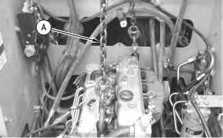
3. Remove Tooling (A) from the engine.
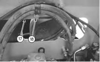
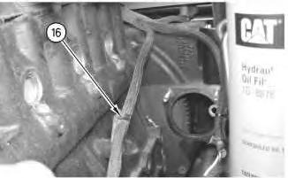
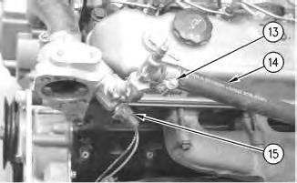
Illustration 7 g00915545
6. Connect harness assembly (15). Install hose (14). Tighten clamp (13) .
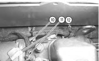
Illustration 8
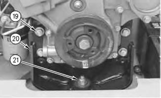
7. Install cable straps (12). Connect wire (10). Install nut (11) .
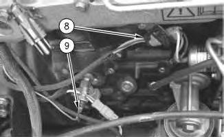
Illustration 9
8. Connect wire (9). Connect harness assembly (8) .
10
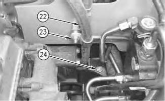
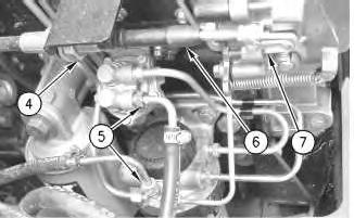
9. Connect hose assemblies(5). Position governor cable (6). Install clip (7). Tighten nut (4) .
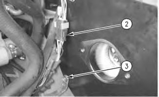
Illustration 11
Note: The piston pump is removed for photographic purposes.
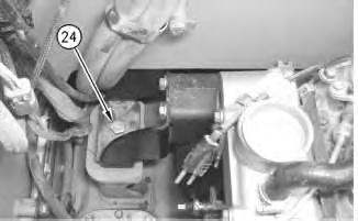
10. Install bolt (3). Connect harness assembly (2) .
12
This is the sample of the manual
Click on the download link for complete Manual
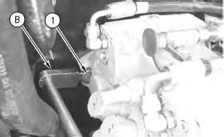
11. Install bolts (1). Use Tooling (B) to torque the boltsto 88 N·m (65 lb ft).
End By:
a. Tilt the cab. Refer to Disassembly and Assembly, "Cab Tilt".
b. Install the air cleaner. Refer to Disassembly and Assembly, "Air Cleaner - Remove and Install".
c. Install the starter. Refer to , "Electric Starting Motor - Remove and Install".
d. Install the alternator. Refer to Disassembly and Assembly, "Alternator - Remove and Install".
e. Install the muffler. Refer to Disassembly and Assembly, "Muffler - Remove and Install".
f. Install the radiator and hydraulic oil cooler. Refer to Disassembly and Assembly, "Radiator and Hydraulic Oil Cooler - Install". Copyright 1993 - 2020 Caterpillar Inc.
Rights Reserved.
Network For SIS Licensees. Fri Apr 17 11:15:04 UTC+0530 2020