The Propane Technical Pocket Guide
DATA AND GUIDANCE FOR RESIDENTIAL AND COMMERCIAL CONSTRUCTION
PROJECTS


DATA AND GUIDANCE FOR RESIDENTIAL AND COMMERCIAL CONSTRUCTION
The Propane Technical Pocket Guide provides general information on how to prepare for the installation of propane systems for residential and commercial consumers. It includes key data and answers important questions relevant to construction professionals planning to incorporate propane in their construction projects.
This guide is not intended to conflict with federal, state, or local ordinances or pertinent industry regulations, including National Fire Protection Association (NFPA) 54 and 58. These should be observed at all times.
The Propane Technical Pocket Guide must not be considered a replacement for proper training on the installation and start-up of propane systems. Propane system installations should always be performed by trained propane professionals. For more information go to your local propane professional or Propane.com/Safety.
Construction pros should visit Propane.com to check out the latest news and insights on building products and trends, learn how to install and operate propane equipment, and find information on constructionrelated events, conferences, and conventions.
The Propane Education & Research Council (PERC) provides free continuing education courses on propane and its many residential and commercial applications, installation specifics, and products, approved by the American Institute of Architects (AIA), National Association of Home Builders (NAHB), U.S. Green Building Council (USGBC), and National Association of the Remodeling Industry (NARI). Fulfill your CEU requirements today at PropaneTrainingAcademy.com.
Propane.com/Safety
Training and informing industry professionals and consumers on the safe handling, storage, and use of propane is a top priority at PERC. PERC’s safety website provides training, resources, and compliance materials.
Retailers.Propane.com
A trained professional can answer your questions about propane applications. Use this handy online tool to find a propane retailer in your area, and you’ll be on your way to a successful, professional propane project.
NATIONAL FIRE PROTECTION ASSOCIATION (NFPA) nfpa.org
NFPA standards govern the use of propane and gas in buildings. Visit nfpa.org for the latest information.
Gravity of Liquid (Water at 1.0) at 60°F
Weight per Gallon of Liquid at 60°F, LB
Specific Heat of Liquid, Btu/LB at 60°F
Limits of Flammability in Air, % of Vapor in Air-Gas Mix:
Latent Heat of Vaporization at Boiling Point:
Total Heating Values After Vaporization: (a) Btu per Cubic Foot
Specific Gravity of Liquid (Water at 1.0) at 15.56°C
Weight per Cubic Meter of Liquid at 15.56°C, kg
Specific Heat of Liquid, Kilojoule/Kilogram at 15.56°C
Flammability
Latent Heat of Vaporization at Boiling Point:
Total Heating Values After Vaporization: (a) Kilojoule per Cubic Meter (b)
* Source Energy Multiplier is the total units of energy that go into generation, processing, and delivery for a particular energy source to produce one unit of energy at the site. The high source energy multiplier for electricity is due in part to transmission and distribution losses that do not occur with propane.
Vapor pressure can be defined as the force exerted by a gas or liquid attempting to escape from a container. It is what forces propane gas from the container through the piping and regulator system to the appliance.
Outside temperature affects the propane vapor pressure in the container. A lower temperature creates lower propane vapor pressure in the container. If container pressure is too low, not enough gas will reach the appliance. Placement of the container below grade can help alleviate wide swings in vapor pressures during the year due to the consistent temperature of the earth.
The table below shows vapor pressures for propane and butane at various outside temperatures.
Table adapted from LP-Gas Serviceman’s Handbook 2012
The best way to determine British thermal unit (Btu) input is from the appliance nameplate or from the manufacturer’s catalog. Add the input of all the appliances for the total load. If specific appliance capacity information is not available, refer to Table 3A below. Remember to allow for appliances that may be installed at a later date, especially if a manifold with unused ports is installed.Some examples may include gas outlets for fireplaces and grills and a switch from an electric to a gas dryer.
If the propane load needs to be in standard cubic feet per hour (SCFH), divide the Btu/hour load by 2,488 to get SCFH. Conversely, the Btu/hour capacity can be obtained from SCFH by multiplying the SCFH figure by 2,488.
Your propane provider will need to know the total Btu load of the system to be served to properly design the propane system, including determining the proper sizing and distance placement of the propane tank, the location of regulators, and the specifications of the underground high-pressure piping system.
Water Heater, Storage, 30- to 40-Gallon Tank
Water Heater, Storage, 50-Gallon Tank
Water Heater, Tankless
2 GPM
4 GPM 6 GPM
Heater, Domestic, Circulating, or Side-Arm
Range, Freestanding, Domestic
Built-In Oven or Broiler Unit, Domestic
Refrigerator
Clothes Dryer, Type 1 (Domestic)
Fireplace, Direct Vent
Reprinted with permission from NFPA 54-2018, National Fuel Gas Code, Copyright© 2017, National Fire Protection Association. This reprinted material is not the complete and official position of the NFPA on the referenced subject, which is represented only by the standard in its entirety and can be obtained through the NFPA web site www.nfpa.org.
A variety of mechanical systems are available for space heating and water heating in homes. These systems have varying energy sources and varying efficiency levels. Table 3B below provides simple calculations that allow contractors and homeowners to estimate the dollars per million Btu depending on the equipment type, efficiency, and energy price. The “$/MMBtu” figure can be compared across different options to evaluate them.
TABLE 3B. OPERATING COSTS AND EQUIPMENT EFFICIENCIES OF RESIDENTIAL SPACE AND WATER HEATING SYSTEMS
*Note that COP does not account for pump energy used to move refrigerant through the extensive ground loop.
The factors affecting vaporization include wetted surface area of the container, liquid level in the container, temperature and humidity surrounding the container, and whether the container is aboveground or underground.
The temperature of the liquid is proportional to the outside air temperature, and the wetted surface area is the tank surface area in contact with the liquid. Therefore, when the outside air temperature is lower or the container has less liquid in it, the vaporization rate of the container is a lower value. Underground tanks will experience a moreconstant temperature year-round, stabilizing vaporization rates due to the stability of soil temperatures.
To determine the proper size of ASME storage tanks, it is important to consider the lowest winter temperature at the location.
See page 10 for more information.
TABLE 4. PROPANE STORAGE TANK CAPACITIES AND MEASUREMENTS*
*These dimensions are only for guidance, as tank sizes and dimensions vary by manufacturer.
A number of assumptions were made in calculating the Btu figures listed in Table 5, noted below:
1. The tank is one-half full.
2. Relative humidity is 70 percent.
3. The tank is under intermittent loading.
4. The tank is located aboveground.
Although none of these conditions may apply, Table 5 can still serve as a good rule of thumb in estimating what a particular tank size will provide under various temperatures. This method uses ASME tank dimensions, liquid level, and a constant value for each 10 percent of liquid to estimate the vaporization capacity of a given tank size at 0 degrees Fahrenheit. Continuous loading is not a very common occurrence on domestic installations, but under continuous loading the withdrawal rates in Table 5 should be multiplied by 0.25.
TABLE 5. MAXIMUM INTERMITTENT WITHDRAWAL RATE (BTU/HOUR) WITHOUT TANK FROSTING* IF LOWEST OUTDOOR TEMPERATURE (AVERAGE FOR 24 HOURS) REACHES ...
*Tank frosting acts as an insulator, reducing the vaporization rate.
Propane jurisdictional zsystems, sometimes referred to as community propane systems or master meter systems, typically serve multiple dwellings, buildings, or businesses.
In general, an operator needs to comply with two primary codes when installing, maintaining, and servicing a jurisdictional system:
• The Code of Federal Regulations (CFR), Title 49, Parts 191 and 192. See ecfr.gov.
• National Fire Protection Association’s Liquefied Petroleum Gas Code (NFPA 58). See nfpa.org.
For more guidance in recognizing jurisdictional systems and the responsibilities required of companies that install and service them, visit Propane.com/safety/safety-articles/propane-jurisdictional-systems and download “Propane Jurisdictional Systems: A Guide to Understanding Basic Fundamentals and Requirements.”
Once the proper size of the ASME storage tank has been determined, careful attention must be given to the most convenient yet safe place for its location on the customer’s property.
The container should be placed in a location that pleases the customer but does not conflict with state and local regulations or NFPA 58, Storage and Handling of Liquefied Petroleum Gases. Refer to this standard and consult with your propane professional to determine the appropriate placement of propane containers.
In general, storage tanks should be placed in an accessible location for filling. Aboveground tanks should be supported by a concrete pad or concrete blocks of appropriate size and reinforcement. For underground propane tanks, properly determining the depth and size of the burial location is critical for placement of the tank. To avoid damage, underground propane tanks should be installed in a location where the delivery truck will not need to drive over septic tanks or other underground amenities. All propane storage tanks should be located away from vehicular traffic.
For ASME containers, the distance from any building openings, external sources of ignition, and intakes to direct-vented gas appliances or mechanical ventilation systems are a critical consideration. See Figures 1 and 2 on pages 13 and 14, respectively.
Refer to NFPA 58 for the minimum distances that these containers must be placed from a building or other objects.
Nearest line of adjoining property that can be built upon
2. Refer to NFPA 58-2017 6.3.4.3. 3. This distance can be reduced to no less than 10 feet for a single container of 1,200 gal (4.5 m3) water capacity or less, provided such container is at least 25 feet from any other LP-gas container of more than 125 gal (0.5 m3) water capacity. Refer to NFPA 58-2017 6.3.1.3.
1. Regardless of its size, any ASME container filled on site must be located so that the filling connection and fixed maximum liquid level gauge are at least 10 feet from any external source of ignition (e.g., open flame, window AC, compressor), intake to direct-vented gas appliance, or intake to a mechanical ventilation system. Refer to NFPA 58-2017 6.3.4.4.
Figure 1 Aboveground ASME Containers. Reprinted with permission from NFPA 58-2017, Liquefied Petroleum Gas Code, Copyright© 2016, National Fire Protection Association. This reprinted material is not the complete and official position of the NFPA on the referenced subject, which is represented only by the standard in its entirety and can be obtained through the NFPA web site www.nfpa.org.
(min) (Note 1)
Inta k e to directv ent appliance Wind o w air conditioner (source of ignition) 2000 gal w.c. or less 10 ft (min) (Note 1) 10 ft (min) (Note 2) 10 ft (min) (Note 1)
(source of ignition)
10 ft (min) (Note 2) Nearest line of adjoining prope r ty that can be b uilt upon
2. No part of an underground container can be less than 10 feet from an important building or line of adjoining property that can be built upon. Refer to NFPA 58-2017 6.3.2.3.
1. The relief valve, filling connection, and fixed maximum liquid level gauge vent connection at the container must be at least 10 feet from any exterior source of ignition, openings into direct-vent appliances, or mechanical ventilation air intakes. Refer to NFPA 58-2017 6.3.4.4.
Figure 2 Underground ASME Containers. Reprinted with permission from NFPA 58-2017, Liquefied Petroleum Gas Code, Copyright© 2016, National Fire Protection Association. This reprinted material is not the complete and official position of the NFPA on the referenced subject, which is represented only by the standard in its entirety and can be obtained through the NFPA web site www.nfpa.org.
Wind o w air conditioner (source of ignition)
10 ft (min) (Note 2)
Cylinder filled on site at the point of use from b ulk t r u c k 3 ft (min) (Note 3)
C r a wl space opening, wind o w s , or e xhaust f an
Cylinders not filled on site at the point of use Inta k e to directv ent appliance 5 ft (min) (Note 1)
Cent r al A C compressor (source of ignition) 5 ft (min) (Note 1) 3 ft (min) (Note 3)
F or SI unit s , 1 ft = 0.3048 m.
2. If the cylinder is filled on site at the point of use from a cargo tank motor vehicle, the filling connection and vent valve must be at least 10 feet from any exterior source of ignition, openings into direct-vent appliances, or mechanical ventilation air intakes. Refer to NFPA 58-2017 6.3.4.4.
1. Five feet minimum from relief valve in any direction away from any exterior source of ignition, openings into direct-vent appliances, or mechanical ventilation air intakes. Refer to NFPA 58-2017
Table 6.3.4.3.
Figure 3 Cylinders. Reprinted with permission from NFPA 58-2017, Liquefied Petroleum Gas Code, Copyright© 2016, National Fire Protection Association. This reprinted material is not the complete and official position of the NFPA on the referenced subject, which is represented only by the standard in its entirety and can be obtained through the NFPA web site www.nfpa.org.
3. Refer to NFPA 58-2017 to 6.3.4.3
Note: Capacities are in 1,000 Btu/Hour. Reprinted with permission from NFPA 58-2017, Liquefied Petroleum Gas Code, Copyright© 2016, National Fire Protection Association. This reprinted material is not the complete and official position of the NFPA on the referenced subject, which is represented only by the standard in its entirety and can be obtained through the NFPA web site www.nfpa.org.
1 Table includes losses for four 90° bends and two end fittings. Tubing runs with larger numbers of bend and/or fittings shall be i ncreased by an equivalent length of tubing to the following equation: L = 1.3n where L is the additional length (feet) of tubing and n is the number of additional fittings and/or bends.
2 EHD (Equivalent Hydraulic Diameter) is a measure of the relative hydraulic efficiency between different tubing sizes. The greater the value of EHD, the greater the gas capacity of the tubing.
Reprinted with permission from NFPA 58-2017, Liquefied Petroleum Gas Code, Copyright© 2016, National Fire Protection Association. This reprinted material is not the complete and official position of the NFPA on the referenced subject, which is represented only by the standard in its entirety and can be obtained through the NFPA web site www.nfpa.org.
Just like tanks, propane pressure regulators come with requirements regarding pipe size and installation distance. Regulators installed on the gas piping system at the side of buildings cannot be placed closer than three feet horizontally from any building opening, such as a window well, that’s lower than the installed regulator. Nor can they be placed closer than five feet from any source of ignition, such as an AC compressor or the intake to a direct-vent appliance. Additional regulations, as well as regulator manufacturer’s instructions, may apply. Check with a propane professional first to ensure you comply with interior gas piping inlet positioning requirements.
4 Interior Gas Piping Inlet Positioning Guidelines
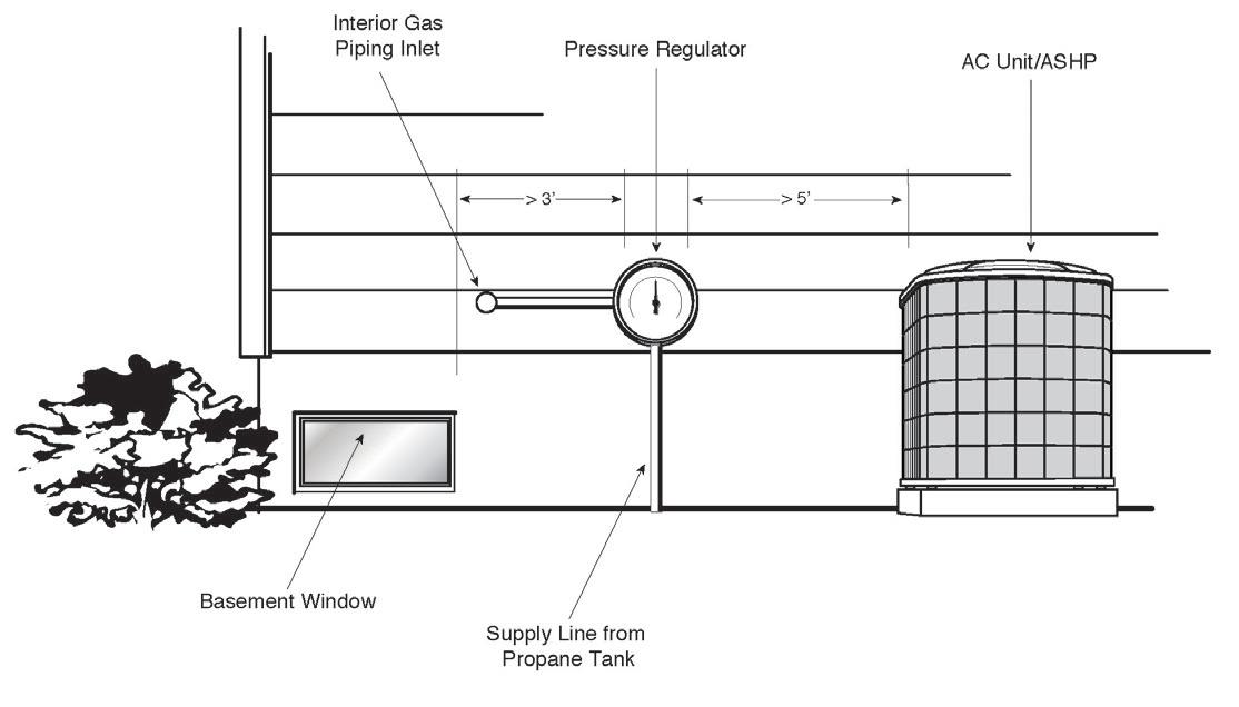
Basement Window
Supply Line from Propane Tank
These guidelines cover the placement of gas piping hangers, supports, and anchors, and have been adapted with permission from NFPA 54-2018, the National Fuel Gas Code. NFPA 54, local codes and standards, and manufacturer recommendations should be observed at all times.
Piping shall be supported with metal pipe hooks, metal pipe straps, metal bands, metal brackets, metal hangers, or building structural components, suitable for the size of the piping, of adequate strength and quality, and located at intervals so as to prevent or damp out excessive vibration. Piping shall be anchored to prevent undue strains on connected appliances and equipment and shall not be supported by other piping. Pipe hangers and supports shall conform to the requirements of ANSI/MSS SP-58, Pipe Hangers and Supports — Materials, Design, Manufacture, Selection, Application, and Installation.
Spacings of supports in gas piping installations shall not be greater than shown in Table 8.
STEEL PIPE, NOMINAL SIZE OF PIPE (INCHES)
SPACING OF SUPPORTS (FEET)
NOMINAL SIZE OF TUBING SMOOTH WALL (INCHES O.D.)
SPACING OF SUPPORTS (FEET)
or 1
1-1/4 or larger (horizontal)
or 3/4
7/8 or 1 (horizontal)
1-1/4 or larger (vertical) Every floor level 1 or larger (vertical) Every floor level
Reprinted with permission from NFPA 54-2018, National Fuel Gas Code, Copyright© 2017, National Fire Protection Association. This reprinted material is not the complete and official position of the NFPA on the referenced subject, which is represented only by the standard in its entirety and can be obtained through the NFPA web site www.nfpa.org.
Spacing of supports of CSST shall be in accordance with the CSST manufacturer’s instructions.
Supports, hangers, and anchors shall be installed so as not to interfere with the free expansion and contraction of the piping between anchors. All parts of the supporting system shall be designed and installed so they are not disengaged by movement of the supported piping.
A home can be made propane-ready with simple steps like installing gas piping (CSST or alternative) to future use points, installing a manifold with available ports, and roughing in for future applications, such as by using a generator-ready electric panel. These steps add value to the home and pave the way for more propane applications. The house cutaway below shows use points for propane to consider both inside and outside the home.


5. The Propane-Ready Home
A. Clothes drying
B. Cooking
C. Space heating
D. Water heating
E. Backup power
F. Outdoor kitchen and amenities
G. Future flexibility
H. Fireplace
I. Pool heating
J. Snowmelt


1. Propane generators are available up to 400kW and some models can be tied together for increased capacity. Refer to manufacturer specifications for guidance on larger generator sizes.
2. Generator manufacturers and models may have varying Btu requirements. Check manufacturer specifications for guidance.
3. Generator Btu load may require separate second-stage propane regulation. The propane system installer will make that determination based on total Btu load of the project.
Diagram and chart based on information provided courtesy of Generac.
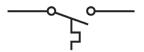
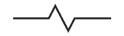
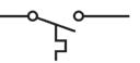
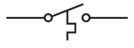
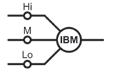
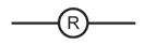
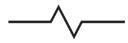
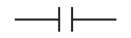
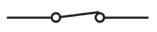
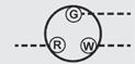
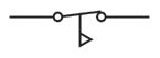
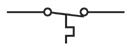
TABLE 10. BASIC SYMBOLS
DEFINITION
Batteries
SYMBOL

Capacitor Fan
Centrifugal switch
Circuit breaker
Door interlock switch
Fan control switch
Fan control, adjustable
Fuse
Fusible link
Gas valve
Ground, chassis
Ground, earth
Igniter


DEFINITION SYMBOL
Limit control switch
Motor, Multi-speed
Motor, Single-speed
Relay coil
Relay switch, NC
Relay switch, NO
Switch, open
Switch, closed
Thermocouple
Thermopile
Thermostat
Transformer
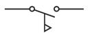
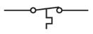
TABLE 11. SENSOR-ACTUATED SWITCHES

Flow
Float


OHM’S LAW
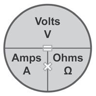
Volts = Amps X Ohms
VOLTAGE READINGS
Millivolts: 1 mV = .001 V
Volts: 1 V = 1 volt
Milli-ohms: 1 mW = .001 W
Ohms: 1 W = 1 ohm
WATT’S LAW
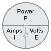
Power (Watts) = Volts X Amps
Microamps: 1 μA = .000001 A
Milliamps: 1 mA = .001 A
Kiloohms or kilo-ohms: 1 kW = 1,000 W
Megohms or mega-ohms: 1 MW = 1,000,000 W
SERIES CIRCUIT
• Voltage drops from one load to the next.
• Current is constant throughout the circuit.
• Resistance of circuit is sum of the resistances of the loads in the circuit.
Amps: 1 A = 1 amp
PARALLEL CIRCUIT
CIRCUIT
• Full source voltage is delivered to each branch in a parallel circuit.
• Total current for a parallel circuit is the sum of the current amounts for each branch in the circuit.
• Total resistance for a parallel circuit is source voltage divided by total current for the circuit, or:
MULTIPLY
Inches
Sq. inches
Sq. feet
Tons (U.S.) PRESSURE AND FLOW RATE
Inches w.c.
in. 1.733 Inches w.c. Inches w.c.
Pounds/sq. in. Bars
Kilopascals
Pounds/sq. in.
Pounds/sq. in. Kilograms/sq. cm.
Pounds/sq. in. Pounds/sq. in.
Atmospheres
Gallons/min.
MISCELLANEOUS
MULTIPLY BY TO OBTAIN
Millimeters Feet
Sq. inches
Meters
Sq. centimeters
Sq. feet 0.0929 Sq. meters
VOLUME AND MASS
Cubic feet
Cubic meters
Liters
Gallons
Liters
Liters
Kilograms
Tonnes
PRESSURE AND FLOW RATE
Inches w.c. 2.488 Millibars
Inches w.c. 0.577 Ounces/sq. in.
Pounds/sq. in.
Pounds/sq. in.
Pounds/sq. in.
Pounds/sq. in.
MISCELLANEOUS
Inches w.c.
Bars
Kilopascals
Kilograms/sq. cm.
Pounds/sq. in.
Cubic meters/hr.
Kilojoules
Watts
Megajoules