BELTCON 20 when thin applications. Large pulley diameters with small shaft diameters will be thin and small shell diameters with large shaft diameters need to be thick. Deciding on the split between the two is the crux of the matter. Reference is made to the T bottom, turbine and flat bottom end disk design.
Beltcon 2 Belt conveyor pulley design, why the failures by Terry King
On studying this paper, the sincerity of the writer comes to the forefront. The facts are presented with the main purpose being to inform and to advise on the way forward. The evidence of this becomes clear in the latter part of the paper. Without boring the reader, he goes into the detail of failed pulleys being returned to their factory with the aim of refurbishing them. The failed pulleys were grouped according to failure modes as these were identified. From the grouping the design intent was captured and referenced accordingly.
What was of great interest was the fact that pulleys were being designed as having either shrink fit shaft to hub connections or bolted pressure elements for the similar. The statement made then was that the shrink fit was difficult to achieve while the locking element pressures could be “readily” achieved. The recommendation then was that smaller pulleys could be made the press fit way and larger units using locking elements. A side note would be to question the relevance of this with modern day high accuracy numerically controlled type manufacturing equipment being used. The focus needs to remain on the shaft deflection. In this paper the keyless friction type shaft connection was described as being the new generation of belt conveyor pulley. The author also makes reference to empirical formula for calculating and sizing the elements.
Shaft sizing;
“The shafts are sized both for the stresses at its point of entry to the hub and for its deflection.” The following formula noted in the presentation is currently widely used and accepted in the South African context. Drive torque is denoted by T The shaft bending moment is denoted by M Combined torsion moment is Te and the combined bending moment Me Thus, combined torsion moment Te2 = T2 + M2 And, combined bending moment Me = 0,5 (M + Te) Derived from this are: Torsion based shaft diameter is dr;
Bending based shaft diameter db:
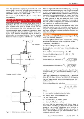
Figure 2 - Turbine end disk
Fs and J s are taken as to be equal since the allowable direct principle stress F s is a fatigue case and the shear stress Js is not. These principle stresses are considered to be 45 N/mm2 for EN3A (070M20) and 55 N/mm2 for EN8 (080M40) shafting. The third shaft diameter will be determined from the “free” shaft deflection. Deflection based diameter is dd; thus
Where: W = nett tension in kN without service factor. " = Bearing centre to hub distance in mm L = Hub spacing in mm E = Youngs modulus for shaft in N/mm2 " = Allowable deflection in radians
Figure 3 - Flat bottom end disk (semi-turbine)
It is noted that the value stated in the Beltcon paper is 0,001 radians for friction type shaft connections hubs which equates to 3,44 minutes. The identical paper published in Bulk Solids handling of April 1986 gives the same value as being 6 minutes for friction type shaft connections and 10 minutes for shrink fit hubs. BULK HANDLING TODAY
Jan/Feb 2020
15


