19 minute read
Pulley Designing Methodology in South Africa


The purpose of this paper is to recap on the current methodology used for designing conveyor pulleys in South Africa. The content of the paper will discuss the deflection requirements and constraints imposed from using locking elements. It will further elude to the additional deflection limits available by making use of the turbine end disk design. The conclusion of the paper will be to table the recommended way forward for designing and evaluating pulley designs for the future. The requirement for this paper came about as a result of fairly large conveyors being supplied to industry where the criteria for the overall allowable shaft deflection being set at 2 minutes at the end disc. Prior to this and to date the industry norm is 5 to 6 minutes. The Beltcon 20 organising committee decided that it will be applicable to have this paper presented in an effort to advise the industry of the history and development of the pulley shaft design process in South Africa. The end goal is to place the industry in a position where they will be able to make an informed decision on the way forward in this regard. The logical place then to start this review will be to present an overview of the presentations conducted, primarily at Beltcon, on this subject. The salient points will be highlighted and discussed. Discussion Papers were presented at Beltcon on the subject of pulley designs as early as Beltcon 1 held in 1981. The paper titled “The design of belt conveyor pulleys” was written by Bernard Lloyd and covered the general design theory of belt conveyor pulleys. This was followed in 1983 with a paper titled “Belt conveyor pulley design – why failures?” by Terry King at Beltcon 2. In this paper he analysed and categorised pulley failures in the field. At Beltcon 3 in 1985, Terry again presented a paper this time titled “The function and mechanism of conveyor pulley drums” where he focussed on the pulley drum design. At Beltcon 6 in 1991, Allan Bell and Max Schenck presented a joint paper titled “Conveyor pulley standards, a possible solution”. Various pulley types and construction methods were reviewed from a standardisation perspective. This was followed by the publishing of then SABS 1669 in 1996. South Africa now had a national standard for the design of conveyor pulleys. The same standard was later republished as SANS 1669 in 2005. The drought on Beltcon papers was broken in 2007 (Beltcon 14) when Allan Lill discussed pulley design relative to using finite element analysis. His paper was titled “conveyor pulley design”.
14 BULK HANDLING TODAY Jan/Feb 2020 This was followed by Gary Styger and Professor Rudolph Laubscher at Beltcon 16 in 2011 on the subject of “An investigation into the effect of manufacturing process on the fatigue performance of conveyor pulleys”, which was also the title of the paper. At the same Beltcon the author presented a paper on pulley practicalities with reference to pulleys fitted with internal bearings. Simon Curry
Advertisement
Outside of Beltcon, Vinit Sethi and Lawrence Nordell wrote a paper titled “Modern pulley design techniques and failure analysis methods” in 2004. This paper was published on the “Ckit” website and a copy of the paper was given to the author by the late Max Schenck who was considered to be one of the leaders of pulley design in South Africa at that time. Extracts of each of these papers will be discussed as relevant for the development of the design processes in South Africa. Beltcon 1 Design of conveyor pulleys by Bernard Lloyd This paper highlighted pulley design from the perspective that Jegkurt engineering were manufacturing pulleys and needed to base their designs on proven technology. To this end they reviewed design criteria from Germany, Australia and parts of the United States. The principal approach which they took reviewed the design of the shaft, the end disk and the shell. Of these the end disk proved to be the element requiring the most attention. In essence the classification of the end disk as being thin or thick was problematic with the real issue being all the variations in pulley diameters relative to shaft diameters for ascertaining thick and
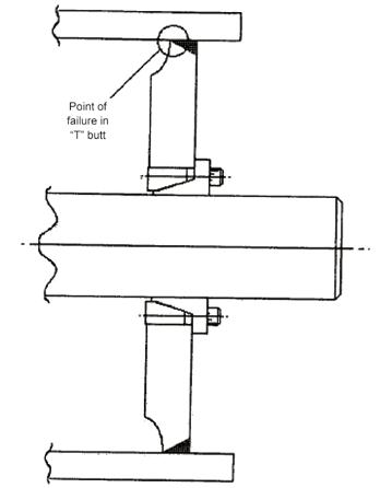
when thin applications. Large pulley diameters with small shaft diameters will be thin and small shell diameters with large shaft diameters need to be thick. Deciding on the split between the two is the crux of the matter. Reference is made to the T bottom, turbine and flat bottom end disk design.
Beltcon 2 Belt conveyor pulley design, why the failures by Terry King On studying this paper, the sincerity of the writer comes to the forefront. The facts are presented with the main purpose being to inform and to advise on the way forward. The evidence of this becomes clear in the latter part of the paper. Without boring the reader, he goes into the detail of failed pulleys being returned to their factory with the aim of refurbishing them. The failed pulleys were grouped according to failure modes as these were identified. From the grouping the design intent was captured and referenced accordingly.
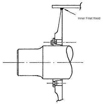
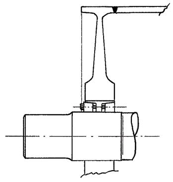
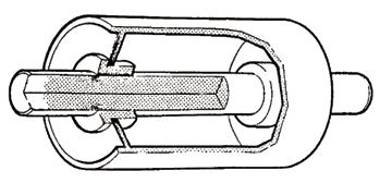
Figure 2 - Turbine end disk
What was of great interest was the fact that pulleys were being designed as having either shrink fit shaft to hub connections or bolted pressure elements for the similar. The statement made then was that the shrink fit was difficult to achieve while the locking element pressures could be “readily” achieved. The recommendation then was that smaller pulleys could be made the press fit way and larger units using locking elements. A side note would be to question the relevance of this with modern day high accuracy numerically controlled type manufacturing equipment being used.
The focus needs to remain on the shaft deflection. In this paper the keyless friction type shaft connection was described as being the new generation of belt conveyor pulley. The author also makes reference to empirical formula for calculating and sizing the elements.
Shaft sizing; “The shafts are sized both for the stresses at its point of entry to the hub and for its deflection.” The following formula noted in the presentation is currently widely used and accepted in the South African context. Drive torque is denoted by T
The shaft bending moment is denoted by M
Combined torsion moment is T e and the combined bending moment M e Thus, combined torsion moment T e 2 = T 2 + M 2 And, combined bending moment M e = 0,5 (M + T e ) Derived from this are:
Torsion based shaft diameter is d r ;
Bending based shaft diameter d b :
Fs and J s are taken as to be equal since the allowable direct principle stress F s is a fatigue case and the shear stress J s is not.
These principle stresses are considered to be 45 N/mm 2 for EN3A (070M20) and 55 N/mm 2 for EN8 (080M40) shafting.
The third shaft diameter will be determined from the “free” shaft deflection.
Deflection based diameter is d d ; thus
Where:
W = nett tension in kN without service factor. " = Bearing centre to hub distance in mm L = Hub spacing in mm
E = Youngs modulus for shaft in N/mm 2
" = Allowable deflection in radians It is noted that the value stated in the Beltcon paper is 0,001 radians for friction type shaft connections hubs which equates to 3,44 minutes. The identical paper published in Bulk Solids handling of April 1986 gives the same value as being 6 minutes for friction type shaft connections and 10 minutes for shrink fit hubs.
Figure 4 – Various locking elements Type A locking element allows 0,05 degrees deflection = 3 minutes of arc. Type B locking element allows 0.06 degrees deflection = 3,6 minutes of arc. Type C locking element has no statement on the allowable deflection. The conclusion was that the hub was too stiff relative to the shell thickness and the stress point or area had moved to the weld area. These stresses in the weld area caused the shell to crack and then fail. The best way to illustrate this is by means of Figure 5. Thorough examining of the failure modes of the pulleys leads to the statement that there should be an allowable ratio between the shell diameter and the shaft diameter. In the conclusion of the paper the requirement for a standard was first to be noted. The second conclusion was that pulley diameters less than three times the diameter of the shaft must be avoided. Hindsight lets us make the statement that this is so obvious. If the outside diameter of the boss on the end disk is too large there is no space for developing and inputting the radii required for a turbine type construction thus placing it into the category of an ordinary rigid connection.
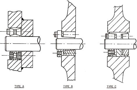
Figure 5 – Failure at weld position
Beltcon 3 The function and Mechanism of conveyor pulley drums by Terry King The author states that pulley shaft failures were adequately covered in the previous paper and that this paper focussed on the shell related failures. For the purposes of our focus on pulley shaft deflection there are two specific aspects which need to be reviewed. Of importance to note is that over the past two years since the last paper, weld crack failures were being noted on the shell local to where the pulley hub was welded to the shell.
Beltcon 6 Conveyor pulley standards – a possible solution presented by Alan Bell and Max Schenck Based on the work done by the presenters at Beltcon 6 “The design of pulleys and the requirement for developing a standard”, this presentation tabled the fundamentals of such a standard. Reference was made to most of the relevant specifications from the various mining houses at that point in time. With reference to bearing centres a narrow and wide range of sizes was identified. These values were tabled accordingly. In essence four types of pulleys were identified being the boss, turbine, L-bottom and T-bottom.
SABS 1669 1991 – Conveyor belt pulleys – Pulley types, construction and dimensions When the national standard was published it signalled a new era in pulley design and manufacture in South Africa. Significant to this paper is the statement in clause 4.7.2 regarding typical allowable deflections of the shaft at the hub. Table 4 of SANS 1669 quantifies all the pulley types with the respective allowable deflection values. For the purpose of this paper specific reference is made to the definition of the shaft using a keyless locking element being 5 minutes. Clause 4.7.2 of the SANS specification covers the design of the shaft, shell and end disc and states that it will be in accordance with acceptable engineering practice and shall provide for a fatigue life as agreed between the manufacturer and the purchaser.
Beltcon 14 Conveyor pulley design presented by Allan Lill This paper was presented on the basis that pulleys can be designed by making use of finite element analysis. The key finding of this paper is that the stresses evaluated in the weld area tend to be higher than what is anticipated by the pulley manufacturers. It was acknowledged that although this would indicate higher levels of failures it was not actually the case. One of the recommendations was that pulleys should be

Figure 9 – L-bottom type pulley
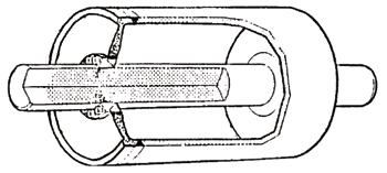
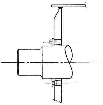
Figure 6 showing rigid type design on right hand side
standardised and not redesigned on every project. This will allow the manufacturers to make use of the finite element analysis process by having less engineering input over a narrower spread of pulley sizes for it being standard.
Figure 10 – T-bottom type pulley
For purposes of this paper there is no reference made in this analysis indicating that shaft deflection could be considered to be a problem. All indications point to the welding and the stresses being developed local to these areas.
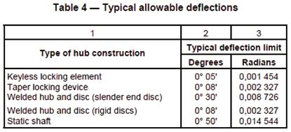
Beltcon 16 An investigation into the effect of the manufacturing process on the fatigue performance of conveyor pulleys by Gary Styger and Prof Rudolph Laubscher The paper presented formed part of a thesis by Styger for his master’s degree. The research was conducted by assessing the stresses developed on the drum surface. A conveyor pulley drum was set up such that the welds on the one side were stress relieved and the other side not. The pulley was then subjected to a load and the residual stresses determined and analysed accordingly. Table 1 – Extract of table 4 from SANS 1669
Styger makes specific reference to the work done by King with a conclusion that more economical pulleys could be designed by making use of FEA. This statement implies that the design procedure followed by Terry King can be construed as being conservative.
Figure 7 – Boss type pulley
The way forward This is where the road ends regarding the development of the pulley design process from a Beltcon perspective. The next step must be to evaluate the recommendations from the locking element manufacturers. None of the locking element suppliers makes direct reference to locking elements being on conveyor pulley applications in conjunction with turbine end disk designs. The reference made is equivalent to that when using a rigid end disk configuration. The allowable shaft deflection limit is set at 2 to 3 minutes of arc. By inference they do not make any allowance for the profile of the end disk of the pulley. At the same time, it must be noted that they do not categorically state that this is the only profile that should be considered. The statement made by the locking element supplier is that this is what is considered to be a maximum requirement.
This paper does not dispute this recommendation. The intent of this paper is to latch onto this recommendation and view it from the perspective that the flexibility of the pulley end disk will allow for the additional deflection which may be present in the system. In the very first Beltcon paper on pulleys Bernard Lloyd makes reference to the fact that conveyor pulley end disks are flexible. At Beltcon 2 Terry King confirms this as well. When Terry presented his next paper at Beltcon 3 he shares a very important finding with the industry. After studying a number of failed pulleys, he makes the statement in his conclusion that there should be a rule governing the ratio of shaft diameter relative to shell diameter. The value quoted is three to one. This conclusion needs to be examined further. By implication the statement he makes is that there is a point where the radial distance between the outside diameter of the shaft and the inside diameter of the shell is insufficient for developing a thin disk conforming to a true turbine profile. Simplistically one can look at the turbine type pulley again. The focus must be shifted to the boss section of the pulley end disk. The outside diameters of the thickened section must satisfy the minimum calculated diameter for the locking element to be assembled and ensuring that there is sufficient material left to retain the magnitude of pressure being developed by the locking element during the tightening process. By means of an example: A 450 mm diameter pulley requires a 150 mm diameter shaft to be fitted. The radial distance between the outside of the shaft and the outside of the shell is calculated as being 150 mm. The locking element will absorb say 25 mm of this distance while the actual hub distance could be in the region of 36 mm larger than the locking element. The 74 mm distance left will prove to be marginal for developing the turbine profile. The shell thickness of the drum would be in the region of 15 mm. Similarly, the root radius will be similar from the shell to the end disk and from the end disk to the boss. This is 30 mm from the 74 mm leaving 44 mm for the turbine profile and thus making it inadequate for the application. What can be done to remedy this? Essentially there are probably four possible ways to address this. 1. The outside diameter of the boss can be reviewed for adequacy. The pressure required to be exerted by the locking element can be reviewed and reduced to be functional for the application. The nett result is that the outside diameter of the centre boss can be reduced and if this is acceptable the process stops. 2. The use of a wider locking element or boss may also be considered. Being wider, the required locking pressure is readily achievable with a smaller boss outside diameter. This improves the situation for developing the turbine profile in the end disk. 3. The third option will be to install a bigger shaft and opt for the option where the shaft diameter is enlarged in accordance with the smaller shaft deflection criteria of what would probably in the region of 2 minutes as per the constraint imposed by the locking element supplier. In this configuration the smaller shell diameter is maintained while the shaft diameter is increased accordingly. As per the example, the shell outside diameter remains at 450 and the shaft diameter increases from 150 mm to say 180 mm. 4. The final option will be to maintain the shaft diameter and increase the shell diameter to where the turbine profile could be readily developed. As per the example the shaft remains at 150 mm and the shell outside diameter could increase to say 600 mm.
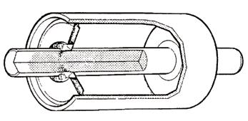
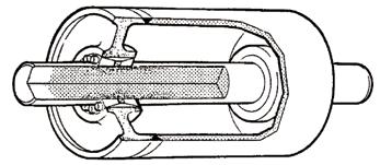
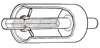
Figure 12 –Turbine type pulley
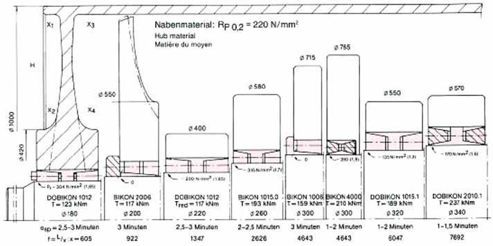
Figure 13 – Shaft to shell ratios
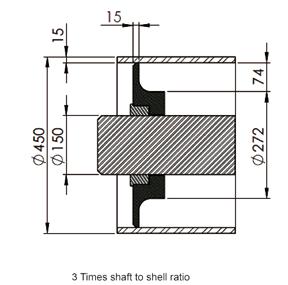

There is far more to the last two paragraphs than initially meets the eye. There is merit in stating that there should be a minimum ratio between the pulley shaft diameter and the pulley shell diameter. What is apparent is that the 1985 logic for using a ratio of 3 is a very coarse value which should be reviewed and refined. Common knowledge is that the outside diameter of the locking element boss can be readily determined. As indicated in the previous section, the turbine profile must be maintained in order to achieve flexibility for ensuring that the end disk will deflect and not be considered a rigid element. The root of the profile local to the shell is dictated by the pulley shell thickness. A set of rules can be developed by the pulley manufacturers to address this issue. The thickness of the boss is determined by the width of the locking element. Setting up a minimum ratio between the width of the locking element boss and the required shell thickness would then be very simplistic. Once this rule is observed, it means that all pulleys will be checked for compliance to this requirement. This is likened to when pulley shafts are designed; three diameters are considered with the largest one being selected. Pulley shell diameters will be selected by making use of 2 parameters. The first parameter will be for determining the minimum diameter required for satisfying the belt construction requirement. The second will be to ensure that a proper turbine end disk is developed in accordance with sound engineering principles ensuring that 5 to 6 minutes of overall shaft deflection is not an issue nor that the design is marginal. Using the example from above, the required width of the locking element housing will be twice the length of the locking element. In this instance the locking element is 40 mm long resulting in the width of the boss being 80 mm. The required outside diameter of the boss is 272 resulting in the radial thickness of the boss being in the region of 61 mm with the shell being 15 mm thick. The minimum ratio should be a value of say 10 times shell thickness for determining height of the turbine profile element. The radial thickness of the boss is 61 mm thick and the shell is 15 mm thick. • The 15 thick shell dictates a 15 mm x 10 ratio = 150 mm turbine element height. • The actual height is 149 mm as per figure 13. • This distance should be adequate for developing a suitable turbine profile for the application. Conclusions The allowable deflection limit of 3 minutes is a requirement localised to the shaft and locking element. The inherent and allowable deflection component as a result of the turbine end disk profile of the pulley will allow the overall shaft deflection to be increased to the current and historic value of 5 to 6 minutes. The transition from a rigid pulley end disk to a turbine profile disk has not been fully defined. The accuracy of modern-day machining methods should be reviewed for ascertaining the relevance of shrink fitted shaft to hub connections in today’s operations. Recommendations The pulley manufacturers must fully define and advise the industry on the transition requirements from a rigid end disk to a possible flexible turbine type profile end disk.To this end the CMA working group on pulleys must be tasked to investigate and research this matter in formalising and making the appropriate recommendations to the industry and the SABS technical committee responsible for the SANS 1669 national standard. If repeatable shrink fitted shaft to hub connections are possible due to modern day high accuracy manufacturing processes and the economics of the process favourable, this application should be re-introduced as another option to industry.
This paper was first presented at the Beltcon Conference in 2019. Copyright is vested with IMHC. www.beltcon.org.za
Simon Curry Tel: (011) 608-4180 Email: scurry@flexco.com
TRACE due diligence solutions are based on internationally accepted best practices and our experience and familiarity with the compliance needs of multinational companies. Services range from a denied parties screening to enhanced due diligence, including TRACE Certified Due Diligence.