


English 2022


CPT is a leading manufacturer of high-quality cutting tools, especially in threading.

Our products are used in a wide variety of industries such as engineering, aerospace, hydraulics, pneumatics, automotive, Oil & Gas, shipbuilding and railways as well as dental and medical.
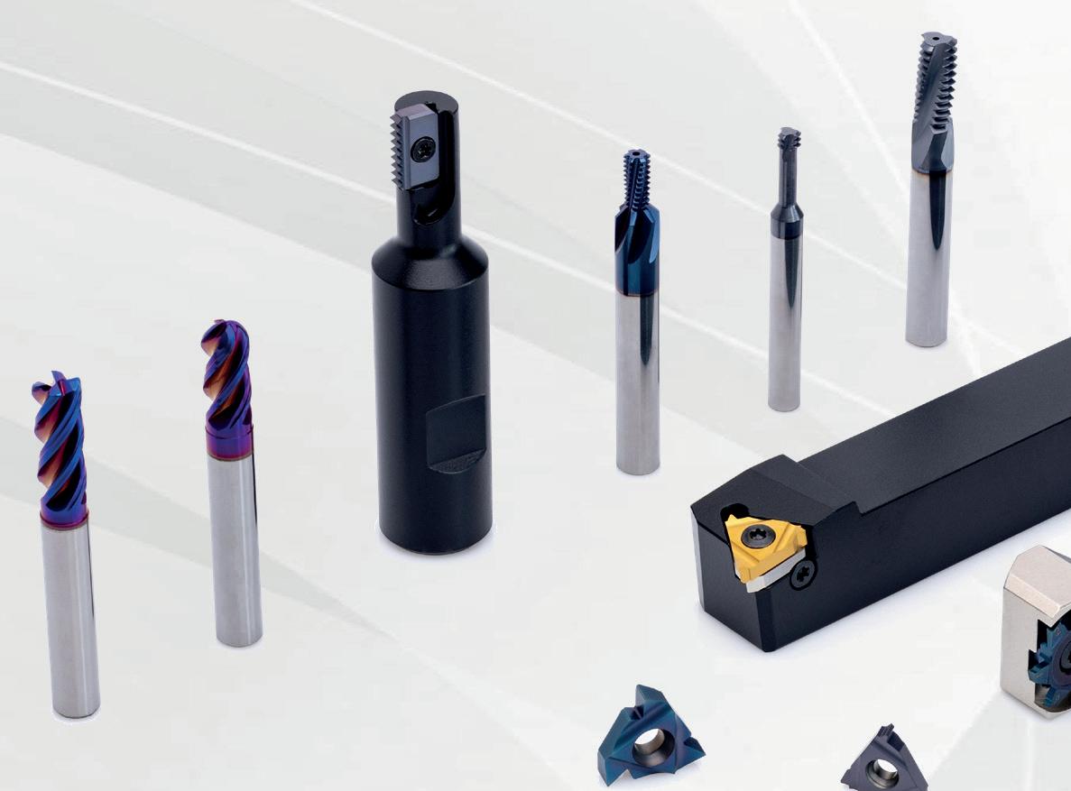
Our product portfolio includes wide range of indexable inserts and holders for thread turning and thread milling, solid carbide thread mills, grooving, swiss tools, solid carbide milling tools and tiny tools.
CPT offers tailor made tools upon customer’s requests.
In addition to our outstanding products, we offer professional technical support by our expert engineering department.
You can rely on CPT products to lead you to higher Productivity, Profitabiliy and Performance.
Our success is based on the commitment to provide our customer’s the highest quality of innovative cutting tools, outstanding technical service and fast deliveries throughout our global distribution network.
CPT offers an online software for Thread Turning and Mill-Thread to assist threading tools users to select and apply the correct tools to machine threads on CNC machining centers.


Both programs will find tools that are suitable for your application, calculate or adjust cutting data depending on the machining capability, and generate CNC program for a variety of controls.
The software is available on our website www.cpt-gewindewerkzeuge.de/home Click on "Software".

In addition to standard products, CPT has a worldwide reputation for the design and manufacture of special tools according to customers' application.


Special tools are supplied in short delivery times.
CPT is fully committed to sustainable production methods. Our green central filtration and waste management system is a good example. This not only maximizes resource use, but also enables us to dispose of our waste in an environmentally responsible way.


A top clamp directing the coolant flow to the cutting edge
Page: A01-32 to 44
Turning adaptors and boring bars for internal threading and grooving applications


Page: A02-7
Page: A01-45 to 50
Boring and profiling with advanced chip breaker
Page: A06-5
Page: A06-12 to 18
Page: A02-13 to 16
Page: A06-34
Page: A06-35 to 38


Page: A06-39 to 41

Threading - Acme & Trapez DIN 103
Boring, Profiling and Facing
Grooving, Circlip Ring Grooves DIN 471/472 Boring and Profiling
Page: A07-1 to
New line of polygon inserts and toolholders
New 25 and 40 mm sized polygon inserts
New GX7 advanced grade - high toughness for optimized performance
New line of 16 mm sized 3 cutting edges inserts and toolholders
G4 - New line of 4 cutting edges turning inserts and toolholders for grooving, parting-off and threading applications


G6 - New line of 6 cutting edges inserts and toolholders for grooving, parting, turning and threading
A09-1
Expanded range of Carbide Shank Turning ToolholdersNPSM
Page: B01-8 and 10
A new product line of indexable Mill-Thread inserts and toolholders including multiple straight flutes for machining long threads from small to large diameters


Page: B03-1 to 10

Threading - Round DIN 405
Dovetail 45˚
Groove Milling DIN 471/472
Groove Milling Multi - Flute DIN 471/472
Front and back corner rounding
Front and back corner rounding - Multi Flute
Page: B07-1 to 30

New Thread-Mills for MJ and UNJ
Section: B08 Section: B08 Page: B08-28

New Thread-Mills for the Dental Implants Industry
Solid Carbide Thread-Mills with internal coolant bore and increased number of flutes for high performance, shorter cycle time and improved tool life


Solid Carbide Thread-Mills with a large number of flutes, for increased productivity and high performance


Thread-Mills for G (BSP) and NPT profiles
Designed to drill, chamfer and thread mill the hole in one operation
Hardcut
Thread-Mills for MJ and UNJ profiles
High productive Solid Carbide Thread-Mills with a large number of flutes for machining hard materials up to 65 HRC
Designed for high feed machining and high metal removal rate
Compatible for a wide range of materials
Performs multiple operations with one tool
Spotting and Drilling Side Milling Chamfering
Slotting Grooving Engraving
Page: B09-9
Page: B09-10 to 12
Page: B09-17
Page: B10-5
Page: B14-20 to 23
New innovative high performance mills
Specifically designed for high volume machining applications


High performance milling tools, designed for high feed rates with shallow cutting depths
Page: B14-34 to 39
For excellent performance
Modular system using the standard CMT tool holders with various shank options

Page: B14-31 to 33
Solid Carbide Radius Fillet End-Mills


Tools for different radius filleting
Two, three and four flutes
Cylindrical shank DIN6535-HA
Tools for 45˚ and 60˚ chamfering and deburring
Four flutes
Cylindrical shank DIN6535-HA (Weldon shank available upon request)


Innovative tools for gear, spline, and rack manufacturing
Page: B16-1 to 4


Page:
A01 | Thread Turning Inserts
A02 | Thread Turning Toolholders and Kits

A03 | Double Sided Thread Turning Inserts and Toolholders

A04 | Thread Turning Technical Section
A05 | Grooving Tools


A06 | Tiny Tools
A07 | Mini Tools
A08 | Swiss Line
A09 | Carbide Shank Turning Toolholders and Inserts


A10 | Thread Whirling
1- 50 1- 24 1- 6 1- 10 1- 4 1- 46 1- 14 1- 50 1- 6 1- 4

Type
VAM 34 HUGHES 35
PAC 35 NPS 36
NPSM 36
Vertical API 37

Vertical API Buttress Casing 38

Vertical API Round 39
Chasers API Round 40
Chasers API Buttress Casing 41
Chasers OTTM Buttress Casing 41
Chasers API Buttress Casing 42
Chasers OTTM Buttress Casing 42
Chasers API Buttress Casing 43
Chasers OTTM Buttress Casing 43
Chasers API Buttress Casing 44
Chasers OTTM Buttress Casing 44


Large Profile Inserts and Toolholders 45-50
Large Profile nserts Trapez - DIN 103
External Holders
Internal Holders
Large Profile agengewinde Inserts DIN 513
External Holders
Internal Holders


3/8” 1/2” 1/2”U
BSPT DIN
TRAPEZ ROUND
SAGE
K20 BMA
P25C BXC BLU HBA
6 5/32 0.5 - 1.25 48


ULTRA MINIATURE *06 IR A60 *06 IL A60 0.6 0.6
8 3/16 0.5 - 1.5 48 - 16 MINIATURE *08 IR A60 *08 IL A60 0.6 0.7 8U 3/16U 1.75 - 2.0 14 - 11 “U” MINIATURE *08U IR/L U60 0.8 4.0


11 1/4 0.5 - 1.5 48 - 16 11 ER A60 11 EL A60 11 IR A60 11 IL A60 0.8 0.9 16 3/8 0.5 - 1.5 48 - 16 16 ER A60 16 EL A60 16 IR A60 16 IL A60 0.8 0.9 16 3/8 1.75 - 3.0 14 - 8 16 ER G60 16 EL G60 16 IR G60 16 IL G60 1.2 1.7
16 3/8 0.5 - 3.0 48 - 8 16 ER AG60 16 EL AG60 16 IR AG60 16 IL AG60 1.2 1.7 22 1/2 3.5 - 5.0 7 - 5 22 ER N60 22 EL N60 22 IR N60 22 IL N60 1.7 2.5 22U 1/2U 5.5 - 8.0 4.5 - 3.25 22U E/I/R/L U60 0.6 11.0 27 5/8 5.5 - 6.0 4.5- 4 27 ER Q60 27 EL Q60 27 IR Q60 27 IL Q60 2.1 3.1 27U 5/8U 6.5 - 9.0 4- 2.75 27U E/I/R/L U60 1.0 13.7


L I.C. Pitch Range
Ordering Code
Ordering Code X Y T in mm TPI Right Hand Left Hand Right Hand Left Hand
16 3/8 0.5 - 1.5 48 - 16 16V ER A60 16V EL A60
16 3/8 1.75 - 3.0 14 - 8 16V ER G60 16V EL G60
16 3/8 0.5 - 3.0 48 - 8 16V ER AG60 16V EL AG60
22 1/2 1.75 - 3.0 14 - 8 22V ER G60 22V EL G60
1.0 0.9 3.6
1.0 1.8 3.6
1.0 1.8 3.6
1.2 1.7 4.0
22 1/2 3.5 - 5.0 7 - 5 22V ER N60 22V EL N60 1.2 2.5 4.8
27 5/8 6.0 - 10.0 4 - 2.5 27V ER V60 27V EL V60 27V IR V60 27V IL V60 1.8 5.2 10.4
Order example: 16V ER G60 BMA
For carbide grade and cutting speed see page A04-2 and 3
6 5/32 0.5
1.25
ULTRA MINIATURE
3/16 0.5 - 1.5 48 - 16 MINIATURE
IR A55 *06 IL A55 0.5 0.6
IR A55 *08 IL A55 0.6 0.7


3/16U 1.75 - 2.0 14 - 11 “U” MINIATURE *08U IR/L U55 0.9 4.0

11 1/4 0.5 - 1.5 48 - 16 11 ER A55 11 EL A55 11 IR A55 11 IL A55 0.8 0.9 16 3/8 0.5 - 1.5 48 - 16 16 ER A55 16 EL A55 16 IR A55 16 IL A55 0.8 0.9 16 3/8 1.75 - 3.0 14 - 8 16 ER G55 16 EL G55 16 IR G55 16 IL G55 1.2 1.7
16 3/8 0.5 - 3.0 48 - 8 16 ER AG55 16 EL AG55 16 IR AG55 16 IL AG55 1.2 1.7 22 1/2 3.5 - 5.0 7 - 5 22 ER N55 22 EL N55 22 IR N55 22 IL N55 1.7 2.5 22U 1/2U 5.5 - 8.0 4.5 - 3.25 22U E/I/R/L U55 0.9 11.0 27 5/8 5.5 - 6.0 4.5 - 4 27 ER Q55 27 EL Q55 27 IR Q55 27 IL Q55 2.0 2.9 27U 5/8U 6.5 - 9.0 4 - 2.75 27U E/I/R/L U55 1.2 13.7
16 ER G55 MXC
small bore threading see page A06-12
example: 16 ER B G55 BMA
carbide grade

cutting speed see page A04-2 and

1.0 0.9
1.0 1.7
1.0 1.8 3.6
1.2 2.5
1.8


Pitch L I.C.
0.25 6 5/32
Ordering Code
Y

Y mm in Right Hand Left Hand
Right Hand Left Hand
*06 IR 0.25 ISO *06 IL 0.25 ISO 0.7 0.3
0.5 6 5/32 *06 IR 0.5 ISO *06 IL 0.5 ISO 0.9 0.5
0.75 6 5/32 ULTRA MINIATURE
*06 IR 0.75 ISO *06 IL 0.75 ISO 0.8 0.5
1.0 6 5/32 *06 IR 1.0 ISO *06 IL 1.0 ISO 0.7 0.6
1.25 6 5/32
*06 IR 1.25 ISO *06 IL 1.25 ISO 0.6 0.6
0.25 8 3/16 *08 IR 0.25 ISO *08 IL 0.25 ISO 0.7 0.3 0.5 8 3/16 *08 IR 0.5 ISO *08 IL 0.5 ISO 0.6 0.5
0.75 8 3/16
1.0 8 3/16
*08 IR 0.75 ISO *08 IL 0.75 ISO 0.6 0.5
*08 IR 1.0 ISO *08 IL 1.0 ISO 0.6 0.6
1.25 8 3/16 *08 IR 1.25 ISO *08 IL 1.25 ISO 0.6 0.7 1.5 8 3/16 *08 IR 1.5 ISO *08 IL 1.5 ISO 0.6 0.7 1.75 8 3/16 *08 IR 1.75 ISO *08 IL 1.75 ISO 0.6 0.8 2.0 8U 3/16U “U” MINIATURE *08U IR/L 2.0 ISO 0.9 4.0
0.25 11 1/4 11 ER 0.25 ISO 11 EL 0.25 ISO 0.6 0.2
0.3 11 1/4 11 ER 0.3 ISO 11 EL 0.3 ISO 0.8 0.3
0.35 11 1/4 11 ER 0.35 ISO 11 EL 0.35 ISO 0.8 0.4 11 IR 0.35 ISO 11 IL 0.35 ISO 0.8 0.3
0.4 11 1/4 11 ER 0.4 ISO 11 EL 0.4 ISO 0.7 0.4 11 IR 0.4 ISO 11 IL 0.4 ISO 0.8 0.4


0.45 11 1/4 11 ER 0.45 ISO 11 EL 0.45 ISO 0.7 0.4 11 IR 0.45 ISO 11 IL 0.45 ISO 0.8 0.4 0.5 11 1/4 11 ER 0.5 ISO 11 EL 0.5 ISO 0.6 0.6 11 IR 0.5 ISO 11 IL 0.5 ISO 0.6 0.6
0.6 11 1/4 11 ER 0.6 ISO 11 EL 0.6 ISO 0.6 0.6 11 IR 0.6 ISO 11 IL 0.6 ISO 0.6 0.6
0.7 11 1/4 11 ER 0.7 ISO 11 EL 0.7 ISO 0.6 0.6 11 IR 0.7 ISO 11 IL 0.7 ISO 0.6 0.6
0.75 11 1/4 11 ER 0.75 ISO 11 EL 0.75 ISO 0.6 0.6 11 IR 0.75 ISO 11 IL 0.75 ISO 0.6 0.6
0.8 11 1/4 11 ER 0.8 ISO 11 EL 0.8 ISO 0.6 0.6 11 IR 0.8 ISO 11 IL 0.8 ISO 0.6 0.6
1.0 11 1/4 11 ER 1.0 ISO 11 EL 1.0 ISO 0.7 0.7 11 IR 1.0 ISO 11 IL 1.0 ISO 0.6 0.7 1.25 11 1/4 11 ER 1.25 ISO 11 EL 1.25 ISO 0.8 0.9 11 IR 1.25 ISO 11 IL 1.25 ISO 0.8 0.8 1.5 11 1/4 11 ER 1.5 ISO 11 EL 1.5 ISO 0.8 1.0 11 IR 1.5 ISO 11 IL 1.5 ISO 0.8 1.0 1.75 11 1/4 11 ER 1.75 ISO 11 EL 1.75 ISO 0.8 1.1 11 IR 1.75 ISO 11 IL 1.75 ISO 0.8 1.1 2.0 11 1/4 11 ER 2.0 ISO 11 EL 2.0 ISO 0.8 1.1 11 IR 2.0 ISO 11 IL 2.0 ISO 0.8 0.9 2.5 11 1/4 11 IR 2.5 ISO 11 IL 2.5 ISO 0.8 1.2
0.25 16 3/8 16 ER 0.25 ISO 16 EL 0.25 ISO 0.6 0.2
0.3 16 3/8
0.3 ISO 0.8 0.3
0.35 ISO 0.8 0.4 16 IR 0.35 ISO 16 IL 0.35 ISO 0.8 0.3
0.4 ISO 0.7 0.4 16 IR 0.4 ISO 16 IL 0.4 ISO 0.8 0.4
EL 0.45 ISO 0.7
ISO
IL
IL
ISO
1.0
ISO
ISO
1.0

Pitch L I.C.
Ordering Code
mm in Right Hand Left Hand
Right Hand Left Hand
3.5 22 1/2 22 ER 3.5 ISO 22 EL 3.5 ISO 1.6 2.3 22 IR 3.5 ISO 22 IL 3.5 ISO 1.6 2.3
4.0 22 1/2 22 ER 4.0 ISO 22 EL 4.0 ISO 1.6 2.3 22 IR 4.0 ISO 22 IL 4.0 ISO 1.6 2.3
4.5 22 1/2 22 ER 4.5 ISO 22 EL 4.5 ISO 1.7 2.4 22 IR 4.5 ISO 22 IL 4.5 ISO 1.6 2.4

5.0 22 1/2 22 ER 5.0 ISO 22 EL 5.0 ISO 1.7 2.5 22 IR 5.0 ISO 22 IL 5.0 ISO 1.6 2.3
5.5 22 1/2 22 ER 5.5 ISO 22 EL 5.5 ISO 1.7 2.6 22 IR 5.5 ISO 22 IL 5.5 ISO 1.6 2.3
6.0 22 1/2 **22 ER 6.0 ISO **22 EL 6.0 ISO 1.9 2.7 22 IR 6.0 ISO 22 IL 6.0 ISO 1.6 2.4
5.5 22U 1/2U 22U ER/L 5.5 ISO 2.3 11.0 22U IR/L 5.5 ISO 2.4 11.0 6.0 22U 1/2U 22U ER/L 6.0 ISO 2.6 11.0 22U IR/L 6.0 ISO 2.1 11.0
5.5 27 5/8 27 ER 5.5 ISO 27 EL 5.5 ISO 1.9 2.7 27 IR 5.5 ISO 27 IL 5.5 ISO 1.6 2.3
6.0 27 5/8 27 ER 6.0 ISO 27 EL 6.0 ISO 2.0 2.9 27 IR 6.0 ISO 27 IL 6.0 ISO 1.8 2.5 8.0 27U 5/8U 27U ER/L 8.0 ISO 2.4 13.7 27U IR/L 8.0 ISO 2.4 13.7 12.0 33U 3/4U 33U ER/L 12.0 ISO 2.5 16.5 33U IR/L 12.0 ISO 3.5 16.9
** Special holder required
Order example: 22 IR 3.5 ISO BMA
For small bore threading see page A06-13


2.0
Order example:


For carbide grade
IR
1.5
BMA
cutting speed see page A04-2
1.0
1.2
1.0 1.3
1.1 1.5
1.2 1.6
1.2
1.0 1.3
1.1 1.5
1.1 1.5
Pitch
0.5 16 3/8 16V ER 0.5 ISO 16V EL 0.5 ISO
0.75 16 3/8 16V ER 0.75 ISO 16V EL 0.75 ISO
0.8 16 3/8 16V ER 0.8 ISO 16V EL 0.8 ISO
1.0 16 3/8 16V ER 1.0 ISO 16V EL 1.0 ISO
Hand Left Hand
1.0 0.6 3.6
1.0 0.6 3.6
1.0 0.6 3.6

1.0 0.7 3.6

1.25 16 3/8 16V ER 1.25 ISO 16V EL 1.25 ISO 1.0 0.9 3.6
1.5 16 3/8 16V ER 1.5 ISO 16V EL 1.5 ISO 1.0 0.9 3.6
1.75 16 3/8 16V ER 1.75 ISO 16V EL 1.75 ISO
1.0 1.2 3.6
1.0 1.3 3.6 2.5 16 3/8 16V ER 2.5 ISO 16V EL 2.5 ISO 1.0 1.5 3.6

2.0 16 3/8 16V ER 2.0 ISO 16V EL 2.0 ISO
3.0 16 3/8 16V ER 3.0 ISO 16V EL 3.0 ISO 1.0 1.7 3.6
* 8.0 27 5/8 27V ER 8.0 ISO 27V EL 8.0 ISO 27V IR 8.0 ISO 27V IL 8.0 ISO 1.8 5.2 10.4
** 10.0 27 5/8 27V ER 10.0 ISO 27V EL 10.0 ISO 27V IR 10.0 ISO 27V IL 10.0 ISO 1.8 5.2 10.4
Pitch
TPI
Ordering Code
Right Hand Left Hand
32 6 5/32
24 6 5/32 ULTRA MINIATURE
*06 IR 28 UN *06 IL 28 UN 0.8 0.6
*06 IR 32 UN *06 IL 32 UN 0.8 0.5 28 6 5/32
*06 IR 24 UN *06 IL 24 UN 0.7 0.6
20 6 5/32 *06 IR 20 UN *06 IL 20 UN 0.6 0.6
18 6 5/32
32 8 3/16
*06 IR 18 UN *06 IL 18 UN 0.6 0.7
*08 IR 32 UN *08 IL 32 UN 0.6 0.5
28 8 3/16 *08 IR 28 UN *08 IL 28 UN 0.6 0.6
24 8 3/16 *08 IR 24 UN *08 IL 24 UN 0.6 0.6
20 8 3/16 MINIATURE
18 8 3/16
*08 IR 20 UN *08 IL 20 UN 0.6 0.7
*08 IR 18 UN *08 IL 18 UN 0.6 0.7
16 8 3/16 *08 IR 16 UN *08 IL 16 UN 0.6 0.7

14 8 3/16 *08 IR 14 UN *08 IL 14 UN 0.6 0.8
13 8 3/16 **08 IR 13 UN 0.8 0.9


13 8U 3/16U *08U IR/L 13 UN 1.0 4.0
12 8U 3/16U “U” MINIATURE
*08U IR/L 12 UN 0.9 4.0
11 8U 3/16U *08U IR/L 11 UN 0.9 4.0
80 11 1/4 11 ER 80 UN 11 EL 80 UN 0.8 0.4 11 IR 80 UN 11 IL 80 UN 0.8 0.4
72 11 1/4 11 ER 72 UN 11 EL 72 UN 0.8 0.4 11 IR 72 UN 11 IL 72 UN 0.8 0.3
64 11 1/4 11 ER 64 UN 11 EL 64 UN 0.8 0.4 11 IR 64 UN 11 IL 64 UN 0.8 0.4
56 11 1/4 11 ER 56 UN 11 EL 56 UN 0.7 0.4 11 IR 56 UN 11 IL 56 UN 0.7 0.4
48 11 1/4 11 ER 48 UN 11 EL 48 UN 0.6 0.6 11 IR 48 UN 11 IL 48 UN 0.6 0.6
44 11 1/4 11 ER 44 UN 11 EL 44 UN 0.6 0.6 11 IR 44 UN 11 IL 44 UN 0.6 0.6
40 11 1/4 11 ER 40 UN 11 EL 40 UN 0.6 0.6 11 IR 40 UN 11 IL 40 UN 0.6 0.6
36 11 1/4 11 ER 36 UN 11 EL 36 UN 0.6 0.6 11 IR 36 UN 11 IL 36 UN 0.6 0.6
32 11 1/4 11 ER 32 UN 11 EL 32 UN 0.6 0.6 11 IR 32 UN 11 IL 32 UN 0.6 0.6
28 11 1/4 11 ER 28 UN 11 EL 28 UN 0.6 0.7 11 IR 28 UN 11 IL 28 UN 0.6 0.7
27 11 1/4 11 ER 27 UN 11 EL 27 UN 0.7 0.8 11 IR 27 UN 11 IL 27 UN 0.7 0.8

24 11 1/4 11 ER 24 UN 11 EL 24 UN 0.7 0.8 11 IR 24 UN 11 IL 24 UN 0.7 0.8
20 11 1/4 11 ER 20 UN 11 EL 20 UN 0.8 0.9 11 IR 20 UN 11 IL 20 UN 0.8 0.9 18 11 1/4 11 ER 18 UN 11 EL 18 UN 0.8 1.0 11 IR 18 UN 11 IL 18 UN 0.8 1.0

16 11 1/4
ER 16 UN 11 EL 16 UN 0.9 1.1 11 IR 16 UN 11 IL 16 UN 0.9 1.1

14 11 1/4 11 ER 14 UN 11 EL 14 UN 0.9 1.1 11 IR 14 UN 11 IL 14 UN 0.9 1.1 13 11 1/4 11 IR 13 UN 11 IL 13 UN 0.8 1.0
IR 12 UN 11 IL 12 UN 0.9 1.1
IR
0.4
0.4
0.4
IR
IR
IR
UN 11 IL 11 UN 0.8 1.1
UN
UN
IL
IL
UN 0.8 0.4
UN 0.8 0.3
Pitch L I.C.
Ordering Code X Y
Ordering Code X Y TPI in Right Hand Left Hand
Right Hand Left Hand
32 16 3/8 16 ER 32 UN 16 EL 32 UN 0.6 0.6 16 IR 32 UN 16 IL 32 UN 0.6 0.6
28 16 3/8 16 ER 28 UN 16 EL 28 UN 0.6 0.7 16 IR 28 UN 16 IL 28 UN 0.6 0.7

27 16 3/8 16 ER 27 UN 16 EL 27 UN 0.7 0.8 16 IR 27 UN 16 IL 27 UN 0.7 0.8
24 16 3/8 16 ER 24 UN 16 EL 24 UN 0.7 0.8 16 IR 24 UN 16 IL 24 UN 0.7 0.8


20 16 3/8 16 ER 20 UN 16 EL 20 UN 0.8 0.9 16 IR 20 UN 16 IL 20 UN 0.8 0.9


18 16 3/8 16 ER 18 UN 16 EL 18 UN 0.8 1.0 16 IR 18 UN 16 IL 18 UN 0.8 1.0
16 16 3/8 16 ER 16 UN 16 EL 16 UN 0.9 1.1 16 IR 16 UN 16 IL 16 UN 0.9 1.1
14 16 3/8 16 ER 14 UN 16 EL 14 UN 1.0 1.2 16 IR 14 UN 16 IL 14 UN 0.9 1.2
13 16 3/8 16 ER 13 UN 16 EL 13 UN 1.0 1.3 16 IR 13 UN 16 IL 13 UN 1.0 1.3
12 16 3/8 16 ER 12 UN 16 EL 12 UN 1.1 1.4 16 IR 12 UN 16 IL 12 UN 1.1 1.4
11.5 16 3/8 16 ER 11.5 UN 16 EL 11.5 UN 1.1 1.5 16 IR 11.5 UN 16 IL 11.5 UN 1.1 1.5
11 16 3/8 16 ER 11 UN 16 EL 11 UN 1.1 1.5 16 IR 11 UN 16 IL 11 UN 1.1 1.5
10 16 3/8 16 ER 10 UN 16 EL 10 UN 1.1 1.5 16 IR 10 UN 16 IL 10 UN 1.1 1.5
9 16 3/8 16 ER 9 UN 16 EL 9 UN 1.2 1.7 16 IR 9 UN 16 IL 9 UN 1.2 1.7
8 16 3/8 16 ER 8 UN 16 EL 8 UN 1.2 1.6 16 IR 8 UN 16 IL 8 UN 1.1 1.5
7 22 1/2 22 ER 7 UN 22 EL 7 UN 1.6 2.3 22 IR 7 UN 22 IL 7 UN 1.6 2.3 6 22 1/2 22 ER 6 UN 22 EL 6 UN 1.6 2.3 22 IR 6 UN 22 IL 6 UN 1.6 2.3 5 22 1/2 22 ER 5 UN 22 EL 5 UN 1.7 2.5 22 IR 5 UN 22 IL 5 UN 1.6 2.3
4.5 22U 1/2U 22U ER/L 4.5 UN 2.0 11.0 22U IR/L 4.5 UN 2.4 11.0 4 22U 1/2U 22U ER/L 4 UN 2.0 11.0 22U IR/L 4 UN 2.4 11.0
4.5 27 5/8 27 ER 4.5 UN 27 EL 4.5 UN 1.9 2.7 27 IR 4.5 UN 27 IL 4.5 UN 1.7 2.4 4 27 5/8 27 ER 4 UN 27 EL 4 UN 2.1 3.0 27 IR 4 UN 27 IL 4 UN 1.8 2.7 3 27U 5/8U 27U ER/L 3 UN 2.5 13.7 27U IR/L 3 UN 2.7 13.7 2 33U 3/4U 33U ER/L 2 UN 2.8 16.5 33U IR/L 2 UN 3.6 16.9
example:
ER
bore threading
carbide grade and cutting speed see page A04-2 and 3
ER
EL
16V EL
16V EL
UN 16V EL
16V EL
16V EL
16V EL
EL
UN
1.0 0.6 3.6
UN 1.0 0.7 3.6
UN 1.0 0.8 3.6
UN 1.0 0.9 3.6
UN 1.0 1.0 3.6
UN 1.0 1.1 3.6
UN 1.0 1.2 3.6
UN 1.0 1.4 3.6
UN
1.0 1.5 3.6
UN 1.0 1.6 3.6
UN 1.2 2.3 4.8
UN 27V EL 3 UN 27V IR
UN 27V IL 3 UN 1.8 5.2 10.4
Pitch
24 16 3/8 2
16 ER 24 UN 2M AE16M 16 IR 24 UN 2M AI16M 1.1 1.7

20 16 3/8 2 16 ER 20 UN 2M AE16M 16 IR 20 UN 2M AI16M 1.4 2.0


18 16 3/8 2 16 ER 18 UN 2M AE16M 16 IR 18 UN 2M AI16M 1.5 2.2
16 16 3/8 2 16 ER 16 UN 2M AE16M 16 IR 16 UN 2M AI16M 1.5 2.3
14 16 3/8 2 16 ER 14 UN 2M AE16M 16 IR 14 UN 2M AI16M 1.7 2.7
12 16 3/8 2 16 ER 12 UN 2M AE16M 16 IR 12 UN 2M AI16M 2.0 3.1
16 22 1/2 3 22 ER 16 UN 3M AE22M 22 IR 16 UN 3M AI22M 2.5 4.0
13 22 1/2 3 22 ER 13 UN 3M AE22M 3.0 4.9
12 22 1/2 2 22 ER 12 UN 2M AE22M 22 IR 12 UN 2M AI22M 2.2 3.4
12 22 1/2 3 22 ER 12 UN 3M AE22M 22 IR 12 UN 3M AI22M 3.3 5.3
8 27 5/8 2 27 ER 8 UN 2M AE27M 27 IR 8 UN 2M AI27M 3.1 4.9
Order example: 22 IR 16 UN 3M BMA
For recommended number of passes see page A04-4
For carbide grade and cutting speed see page A04-2 and 3
Pitch L I.C.
26 6 5/32
22 6 5/32 ULTRA MINIATURE
20 6 5/32
18 6 5/32
Code
Code X Y TPI in Right Hand Left Hand Right Hand Left Hand
*06 IR 26 W *06 IL 26 W 0.7 0.6
*06 IR 22 W *06 IL 22 W 0.6 0.6
*06 IR 20 W *06 IL 20 W 0.6 0.7
*06 IR 18 W *06 IL 18 W 0.6 0.7
28 8 3/16 *08 IR 28 W *08 IL 28 W 0.6 0.6


24 8 3/16 *08 IR 24 W *08 IL 24 W 0.6 0.6
20 8 3/16
*08 IR 20 W *08 IL 20 W 0.6 0.7 19 8 3/16 *08 IR 19 W *08 IL 19 W 0.6 0.7
18 8 3/16
16 8 3/16
MINIATURE
*08 IR 18 W *08 IL 18 W 0.6 0.7
*08 IR 16 W *08 IL 16 W 0.6 0.7

14 8U 3/16U *08U IR/L 14 W 1.0 4.0
12 8U 3/16U “U” MINIATURE *08U IR/L 12 W 0.9 4.0 11 8U 3/16U *08U IR/L 11 W 0.9 4.0

72 11 1/4 11 ER 72 W 11 EL 72 W 11 IR 72 W 11 IL 72 W 0.7 0.4
60 11 1/4 11 ER 60 W 11 EL 60 W 11 IR 60 W 11 IL 60 W 0.7 0.4
56 11 1/4 11 ER 56 W 11 EL 56 W 11 IR 56 W 11 IL 56 W 0.7 0.4
48 11 1/4 11 ER 48 W 11 EL 48 W 11 IR 48 W 11 IL 48 W 0.6 0.6 40 11 1/4 11 ER 40 W 11 EL 40 W 11 IR 40 W 11 IL 40 W 0.6 0.6
36 11 1/4 11 ER 36 W 11 EL 36 W 11 IR 36 W 11 IL 36 W 0.6 0.6
32 11 1/4 11 ER 32 W 11 EL 32 W 11 IR 32 W 11 IL 32 W 0.6 0.6
28 11 1/4 11 ER 28 W 11 EL 28 W 11 IR 28 W 11 IL 28 W 0.6 0.7
26 11 1/4 11 ER 26 W 11 EL 26 W 11 IR 26 W 11 IL 26 W 0.7 0.7 24 11 1/4 11 ER 24 W 11 EL 24 W 11 IR 24 W 11 IL 24 W 0.7 0.8
22 11 1/4 11 ER 22 W 11 EL 22 W 11 IR 22 W 11 IL 22 W 0.8 0.9
20 11 1/4 11 ER 20 W 11 EL 20 W 11 IR 20 W 11 IL 20 W 0.8 0.9 19 11 1/4 11 ER 19 W 11 EL 19 W 11 IR 19 W 11 IL 19 W 0.8 1.0 18 11 1/4 11 ER 18 W 11 EL 18 W 11 IR 18 W 11 IL 18 W 0.8 1.0 16 11 1/4 11 ER 16 W 11 EL 16 W 11 IR 16 W 11 IL 16 W 0.9 1.1 14 11 1/4 11 ER 14 W 11 EL 14 W 11 IR 14 W 11 IL 14 W 0.9 1.1 12 11 1/4 11 IR 12 W 11 IL 12 W 0.1 1.1 11 11 1/4 11 IR 11 W 11 IL 11 W 0.9 1.2 72 16 3/8 16 ER
Pitch L I.C.
Ordering Code
Ordering Code X Y TPI in Right Hand Left Hand Right Hand Left Hand 22 16 3/8 16 ER 22 W 16 EL 22 W 16 IR 22 W 16 IL 22 W 0.8 0.9 20 16 3/8 16 ER 20 W 16 EL 20 W 16 IR 20 W 16 IL 20 W 0.8 0.9 19 16 3/8 16 ER 19 W 16 EL 19 W 16 IR 19 W 16 IL 19 W 0.8 1.0


18 16 3/8 16 ER 18 W 16 EL 18 W 16 IR 18 W 16 IL 18 W 0.8 1.0 16 16 3/8 16 ER 16 W 16 EL 16 W 16 IR 16 W 16 IL 16 W 0.9 1.1
14 16 3/8 16 ER 14 W 16 EL 14 W 16 IR 14 W 16 IL 14 W 1.0 1.2 12 16 3/8 16 ER 12 W 16 EL 12 W 16 IR 12 W 16 IL 12 W 1.1 1.4
11 16 3/8 16 ER 11 W 16 EL 11 W 16 IR 11 W 16 IL 11 W 1.1 1.5 10 16 3/8 16 ER 10 W 16 EL 10 W 16 IR 10 W 16 IL 10 W 1.1 1.5 9 16 3/8 16 ER 9 W 16 EL 9 W 16 IR 9 W 16 IL 9 W 1.2 1.7
8 16 3/8 16 ER 8 W 16 EL 8 W 16 IR 8 W 16 IL 8 W 1.2 1.5
7 22 1/2 22 ER 7 W 22 EL 7 W 22 IR 7 W 22 IL 7 W 1.6 2.3

6 22 1/2 22 ER 6 W 22 EL 6 W 22 IR 6 W 22 IL 6 W 1.6 2.3 5 22 1/2 22 ER 5 W 22 EL 5 W 22 IR 5 W 22 IL 5 W 1.7 2.4
4.5 22U 1/2U 22U E/I/R/L 4.5 W 2.3 11.0 4 22U 1/2U 22U E/I/R/L 4 W 2.8 11.0 4.5 27 5/8 27 ER 4.5 W 27 EL 4.5 W 27 IR 4.5 W 27 IL 4.5 W 1.8 2.6 4 27 5/8 27 ER 4 W 27 EL 4 W 27 IR 4 W 27 IL 4 W 2.0 2.9 3.5 27U 5/8U 27U E/I/R/L 3.5 W 2.1 13.7 3.25 27U 5/8U 27U E/I/R/L 3.25 W 2.0 13.7 3 27U 5/8U 27U E/I/R/L 3 W 2.3 13.7
2.75 27U 5/8U 27U E/I/R/L 2.75 W 2.4 13.7
*2.625 27U 5/8U 27U E/I/R/L 2.625 W 2.5 13.7
*2.5 27U 5/8U 27U E/I/R/L 2.5 W 2.8 13.7
IR
A04-2
28 11 1/4
24 11 1/4
11 1/4
19 11 1/4
18 11 1/4
16 11 1/4
11 IR
11 IR
11 IR B 20
11 IR B 19
0.6 0.6
0.6 0.6
0.8 0.9
0.8 0.9
11 IR B 18 W 0.8 0.9
11 IR B 16 W 0.8 0.9
14 11 1/4 11 IR B 14 W 0.8 0.9
19 16 3/8
14 16 3/8
11 16 3/8
10 16 3/8
B 19
B 16
ER B 14
16
14
12
11
16 IR B 16 W 0.9 1.1
16 IR B 19 W 0.8 1.0 16 16 3/8
16 IR B 14 W 1.0 1.2
ER B 11 W 16 IR B 11 W 1.1 1.5

ER B 10
16 IR B 10 W 1.1 1.5
Pitch L I.C.
TPI in of Teeth
Code Anvil X
14 16 3/8 2 16 ER 14 W 2M AE16M 16 IR 14 W 2M AI16M 1.7 2.7
11 16 3/8 2 16 ER 11 W 2M AE16M 16 IR 11 W 2M AI16M 2.1 3.4
14 22 1/2 3 22 ER 14 W 3M AE22M 22 IR 14 W 3M AI22M 2.8 4.5


11 22 1/2 2 22 ER 11 W 2M AE22M 22 IR 11 W 2M AI22M 2.1 3.4
Order example: 16 ER 14 W 2M MXC
For recommended number of passes see page A04-4
For carbide grade and cutting speed see page A04-2 and 3
NPT
NPT
NPT
NPT
NPT
NPT
NPT
NPT
NPT
NPT
NPT
NPT
NPT
NPT
NPT
16 3/8 16
only in BXC
BMA
Order example: 16 ER 14 NPT MXC
IL
IL
IL
IL
NPT
NPT
NPT
NPT
NPT 0.8 1.0
NPT 0.8 1.0
NPT 0.7 0.8
NPT 0.8 1.0
NPT 0.9 1.2


NPT 16 EL 11.5 NPT 16 IR 11.5 NPT 16 IL 11.5 NPT 1.1 1.5
NPT 16 EL 8 NPT 16 IR 8 NPT 16 IL 8 NPT 1.3 1.8

small bore threading see page A06-16
IR
11.5 NPT BMA
NPT
carbide grade and cutting speed see page A04-2 and


NPT
NPT
1.2
NPT 1.1 1.5
NPT 1.3 1.8


1/4
1/4
3/8
16 3/8
NPTF
NPTF
NPTF *06 IL 27 NPTF 0.7 0.6


IR 27 NPTF *08 IL 27 NPTF 0.6 0.6


IR 18 NPTF *08 IL 18 NPTF 0.6 0.6
EL 27 NPTF 11 IR 27 NPTF 11 IL 27 NPTF 0.7 0.7
EL 18 NPTF 11 IR 18 NPTF 11 IL 18 NPTF 0.8 1.0
NPTF 11 EL 14 NPTF 11 IR 14 NPTF 11 IL 14 NPTF 0.8 1.0
NPTF 16 EL 27 NPTF 16 IR 27 NPTF 16 IL 27 NPTF 0.7 0.7
NPTF 16 EL 18 NPTF 16 IR 18 NPTF 16 IL 18 NPTF 0.8 1.0
NPTF 16 EL 14 NPTF 16 IR 14 NPTF 16 IL 14 NPTF 0.9 1.2 11.5 16 3/8 16

16 3/8
11.5 NPTF 16 EL 11.5 NPTF 16 IR 11.5 NPTF 16 IL 11.5 NPTF 1.1 1.5 8 16 3/8 16 ER 8 NPTF 16 EL 8 NPTF 16 IR 8 NPTF 16 IL 8 NPTF 1.3 1.8
TPI
28 6 5/32
Right Hand Left Hand
*06 IR 28 BSPT *06 IL 28 BSPT 0.7 0.6

28 8 3/16 *08 IR 28 BSPT *08 IL 28 BSPT 0.6 0.6
19 8 3/16
28 11 1/4
19 11 1/4
*08 IR 19 BSPT *08 IL 19 BSPT 0.6 0.6

11 IR 28 BSPT 11 IL 28 BSPT 0.6 0.6
11 IR 19 BSPT 11 IL 19 BSPT 0.8 0.9
14 11 1/4 11 IR 14 BSPT 11 IL 14 BSPT 0.9 1.0 11 11 1/4 11 IR 11 BSPT 11 IL 11 BSPT 0.9 1.2
28 16 3/8 16 ER 28 BSPT 16 EL 28 BSPT 16 IR 28 BSPT 16 IL 28 BSPT 0.6 0.6
19 16 3/8 16 ER 19 BSPT 16 EL 19 BSPT 16 IR 19 BSPT 16 IL 19 BSPT 0.8 0.9
14 16 3/8 16 ER 14 BSPT 16 EL 14 BSPT 16 IR 14 BSPT 16 IL 14 BSPT 1.0 1.2
11 16 3/8 16 ER 11 BSPT 16 EL 11 BSPT 16 IR 11 BSPT 16 IL 11 BSPT 1.1 1.5
only
Order example: 11 IR 14 BSPT BMA
(1) Special holder is required or standard holder can be amended by customer.


Pitch L I.C.
TPI in
Ordering

Right
Ordering Code

Left Hand
16 8 3/16 MINIATURE **08 IR 16 ACME **08 IL 16 ACME 0.6 0.6


14 8U 3/16U
12 8U 3/16U “U” MINIATURE
*08U IR/L 14 ACME 0.8 4.0
*08U IR/L 12 ACME 0.8 4.0
10 8U 3/16U *08U IR/L 10 ACME 0.8 4.0
16 11 1/4 11 ER 16 ACME 11 EL 16 ACME 11 IR 16 ACME 11 IL 16 ACME 0.9 1.0 16 16 3/8 16 ER 16 ACME 16 EL 16 ACME 16 IR 16 ACME 16 IL 16 ACME 0.9 1.0
14 16 3/8 16 ER 14 ACME 16 EL 14 ACME 16 IR 14 ACME 16 IL 14 ACME 1.0 1.2
12 16 3/8 16 ER 12 ACME 16 EL 12 ACME 16 IR 12 ACME 16 IL 12 ACME 1.1 1.2
10 16 3/8 16 ER 10 ACME 16 EL 10 ACME 16 IR 10 ACME 16 IL 10 ACME 1.3 1.3 8 16 3/8 16 ER 8 ACME 16 EL 8 ACME 16 IR 8 ACME 16 IL 8 ACME 1.5 1.5
6 16 3/8 16 ER 6 ACME 16 EL 6 ACME 16 IR 6 ACME 16 IL 6 ACME 1.7 1.8
6 22 1/2 22 ER 6 ACME 22 EL 6 ACME 22 IR 6 ACME 22 IL 6 ACME 1.8 2.1
5 22 1/2 22 ER 5 ACME 22 EL 5 ACME 22 IR 5 ACME 22 IL 5 ACME 2.0 2.3
4 22 1/2 22 ER 4 ACME 22 EL 4 ACME 22 IR 4 ACME 22 IL 4 ACME 2.1 2.2
4 22U 1/2U 22U ER/L 4 ACME 22U IR/L 4 ACME 2.3 11.0

4 27 5/8 27 ER 4 ACME 27 EL 4 ACME 27 IR 4 ACME 27 IL 4 ACME 2.3 2.7
3 27U 5/8U 27U ER/L 3 ACME 27U IR/L 3 ACME 2.8 13.7
33U 3/4U
ER/L
ACME 33U IR/L 2 ACME 4.3 16.9
* Minimum bore: Ø55 mm ** Minimum bore: Ø76 mm
Order example: 27V ER 2 ACME BMA
For carbide grade and cutting speed see page A04-2 and 3

Pitch L I.C.
16 8 3/16 MINIATURE
14 8U 3/16U
Ordering Code
Ordering Code X Y TPI in Right Hand Left Hand
Right Hand Left Hand
**08 IR 16 STACME **08 IL 16 STACME 0.6 0.6
*08U IR/L 14 STACME 0.8 4.0
12 8U 3/16U “U” MINIATURE *08U IR/L 12 STACME 0.9 4.0
10 8U 3/16U *08U IR/L 10 STACME 1.0 4.0
16 11 1/4 11 ER 16 STACME 11 EL 16 STACME 1.0 1.0
16 16 3/8 16 ER 16 STACME 16 EL 16 STACME 16 IR 16 STACME 16 IL 16 STACME 1.0 1.0
14 16 3/8 16 ER 14 STACME 16 EL 14 STACME 16 IR 14 STACME 16 IL 14 STACME 1.1 1.1
12 16 3/8 16 ER 12 STACME 16 EL 12 STACME 16 IR 12 STACME 16 IL 12 STACME 1.2 1.2
10 16 3/8 16 ER 10 STACME 16 EL 10 STACME 16 IR 10 STACME 16 IL 10 STACME 1.3 1.3
8 16 3/8 16 ER 8 STACME 16 EL 8 STACME 16 IR 8 STACME 16 IL 8 STACME 1.5 1.5
6 16 3/8 16 ER 6 STACME 16 EL 6 STACME 16 IR 6 STACME 16 IL 6 STACME 1.8 1.8
6 22 1/2 22 ER 6 STACME 22 EL 6 STACME 22 IR 6 STACME 22 IL 6 STACME 1.8 1.8
5 22 1/2 22 ER 5 STACME 22 EL 5 STACME 22 IR 5 STACME 22 IL 5 STACME 2.0 2.3
4 22 1/2 22 ER 4 STACME 22 EL 4 STACME 22 IR 4 STACME 22 IL 4 STACME 2.3 2.4
4 22U 1/2U 22U ER/L 4 STACME 22U IR/L 4 STACME 2.5 11.0


3 22U 1/2U 22U ER/L 3 STACME 22U IR/L 3 STACME 3.3 11.0
4 27 5/8 27 ER 4 STACME 27 EL 4 STACME 27 IR 4 STACME 27 IL 4 STACME 2.3 2.4
3 27 5/8 27 ER 3 STACME 27 EL 3 STACME 27 IR 3 STACME 27 IL 3 STACME 2.8 2.9
2 33U 3/4U 33U ER/L 2 STACME 33U IR/L 2 STACME 5.0 16.9
* Available only in BXC
** One cutting edge
BMA grades

Order example: 22 IR 5 STACME MXC
carbide grade and cutting speed see page A04-2 and 3
IR 2 TR 16 IL 2 TR 1.0 1.3
IR 3 TR 16 IL 3 TR 1.3 1.5
TR 16 IR 4 TR 16 IL 4 TR 1.3 1.5
16U 3/8U ***16U IR/L 5 TR 2.3 8.2
4.0 22 1/2
TR 22 EL 4 TR 22 IR 4 TR 22 IL 4 TR 1.8 1.9 5.0 22 1/2 22 ER 5 TR 22 EL 5 TR 22 IR 5 TR 22 IL 5 TR 2.0 2.4

6.0 22 1/2 22 ER 6 TR 22 EL 6 TR 22 IR 6 TR 22 IL 6 TR 2.0 2.4
6.0 22U 1/2U 22U ER/L 6 TR 22U IR/L 6 TR 2.0 11.0
7.0 22U 1/2U 22U ER/L 7 TR 22U IR/L 7 TR 2.3 11.0
7.0 22U 1/2U 22U IR/L 7 TR40 2.6 11.0
8.0 22U 1/2U 22U ER/L 8 TR 22U IR/L 8 TR 2.5 11.0
6.0 27 5/8 27 ER 6 TR 27 EL 6 TR 27 IR 6 TR 27 IL 6 TR 2.3 2.7
7.0 27 5/8 27 ER 7 TR 27 EL 7 TR 27 IR 7 TR 27 IL 7 TR 2.2 2.6
8.0 27U 5/8U 27U ER/L 8 TR 27U IR/L 8 TR 2.5 13.7
9.0 27U 5/8U 27U ER/L 9 TR 27U IR/L 9 TR 3.0 13.7
10.0 27U 5/8U **27U ER/L 10 TR **27U IR/L 10 TR 3.2 13.7 12.0 33U 3/4U 33U ER/L 12 TR 33U IR/L 12 TR 3.9 16.9
Available only in BXC and
One cutting edge
To be used only with holder SIR/L0014M16UB on page A02-10


example: 22 IR 5 TR MXC
Special holder is required or standard holder can be amended by customer.
Special holder is required or standard holder can be amended by customer or to used with holders: SIR/L0012L16B; SIR/L0014L16B

Only for
be used only with
SIR/L0025S22UB


Pitch L I.C.
28 08 3/16
24 08 3/16
20 08 3/16
18 08 3/16
MINIATURE
13 08U 3/16U "U" MINIATURE
X Y TPI in Right Hand Left Hand Right Hand Left Hand
*08 IR 28 UNJ *08 IL 28 UNJ 0.6 0.6
*08 IR 24 UNJ *08 IL 24 UNJ 0.6 0.6
*08 IR 20 UNJ *08 IL 20 UNJ 0.6 0.7
*08 IR 18 UNJ *08 IL 18 UNJ 0.6 0.7
*08 UIR/L 13 UNJ 0.9 4.0


48 11 1/4 11 ER 48 UNJ 11 EL 48 UNJ 11 IR 48 UNJ 11 IL 48 UNJ 0.6 0.6
44 11 1/4 11 ER 44 UNJ 11 EL 44 UNJ 11 IR 44 UNJ 11 IL 44 UNJ 0.6 0.6
40 11 1/4 11 ER 40 UNJ 11 EL 40 UNJ 11 IR 40 UNJ 11 IL 40 UNJ 0.6 0.6
36 11 1/4 11 ER 36 UNJ 11 EL 36 UNJ 11 IR 36 UNJ 11 IL 36 UNJ 0.6 0.6
32 11 1/4 11 ER 32 UNJ 11 EL 32 UNJ 11 IR 32 UNJ 11 IL 32 UNJ 0.6 0.6
28 11 1/4 11 ER 28 UNJ 11 EL 28 UNJ 11 IR 28 UNJ 11 IL 28 UNJ 0.6 0.6
24 11 1/4 11 ER 24 UNJ 11 EL 24 UNJ 11 IR 24 UNJ 11 IL 24 UNJ 0.7 0.8
20 11 1/4 11 ER 20 UNJ 11 EL 20 UNJ 11 IR 20 UNJ 11 IL 20 UNJ 0.8 0.9
18 11 1/4 11 ER 18 UNJ 11 EL 18 UNJ 11 IR 18 UNJ 11 IL 18 UNJ 0.8 1.0
16 11 1/4 11 ER 16 UNJ 11 EL 16 UNJ 11 IR 16 UNJ 11 IL 16 UNJ 0.8 1.0
14 11 1/4 11 ER 14 UNJ 11 EL 14 UNJ 11 IR 14 UNJ 11 IL 14 UNJ 0.9 1.0
48 16 3/8 16 ER 48 UNJ 16 EL 48 UNJ 16 IR 48 UNJ 16 IL 48 UNJ 0.6 0.6
44 16 3/8 16 ER 44 UNJ 16 EL 44 UNJ 16 IR 44 UNJ 16 IL 44 UNJ 0.6 0.6
40 16 3/8 16 ER 40 UNJ 16 EL 40 UNJ 16 IR 40 UNJ 16 IL 40 UNJ 0.6 0.6
36 16 3/8 16 ER 36 UNJ 16 EL 36 UNJ 16 IR 36 UNJ 16 IL 36 UNJ 0.6 0.6
32 16 3/8 16 ER 32 UNJ 16 EL 32 UNJ 16 IR 32 UNJ 16 IL 32 UNJ 0.6 0.6
28 16 3/8 16 ER 28 UNJ 16 EL 28 UNJ 16 IR 28 UNJ 16 IL 28 UNJ 0.6 0.6
24 16 3/8 16 ER 24 UNJ 16 EL 24 UNJ 16 IR 24 UNJ 16 IL 24 UNJ 0.7 0.8 20 16 3/8 16 ER 20 UNJ 16 EL 20 UNJ 16 IR 20 UNJ 16 IL 20 UNJ 0.8 0.9
18 16 3/8 16 ER 18 UNJ 16 EL 18 UNJ 16 IR 18 UNJ 16 IL 18 UNJ 0.8 1.0
16 16 3/8 16 ER 16 UNJ 16 EL 16 UNJ 16 IR 16 UNJ 16 IL 16 UNJ 0.8 1.0
14 16 3/8 16 ER 14 UNJ
UNJ 16 IR
IR
UNJ
UNJ
UNJ
UNJ
UNJ 16 IL
UNJ
IL
UNJ 1.0 1.2
UNJ 1.0 1.3
IR 12 UNJ 16 IL 12 UNJ 1.1 1.4
IR
IR
IR
IR
UNJ
UNJ
UNJ
UNJ
IL
IL
IL
IL
UNJ 1.1 1.5
UNJ 1.1 1.5
UNJ 1.2
UNJ 1.2 1.6
Pitch L I.C.
0.5 11 1/4
0.7 11 1/4
0.75 11 1/4
0.8 11 1/4
1.0 11 1/4
Ordering Code

Ordering Code X Y mm in Right Hand
Right Hand
11 IR 0.5 MJ
0.5 0.4
11 IR 0.7 MJ 0.6 0.5
11 IR 0.75 MJ 0.6 0.5
11 IR 0.8 MJ 0.6 0.6
11 ER 1.0 MJ
1.25 11 1/4 11 ER 1.25 MJ
1.5 11 1/4 11 ER 1.5 MJ
2.0 11 1/4
11 IR 1.0 MJ 0.7 0.8
11 IR 1.25 MJ 0.8 0.9
11 IR 1.5 MJ 0.8 1.0

11 IR 2.0 MJ 0.9 1.0
0.5 16 3/8 16 ER 0.5 MJ 0.6 0.6
0.7 16 3/8 16 ER 0.7 MJ 0.6 0.6
0.75 16 3/8 16 ER 0.75 MJ
16 IR 0.75 MJ 0.5 0.5
0.8 16 3/8 16 ER 0.8 MJ 16 IR 0.8 MJ 0.6 0.6
1.0 16 3/8 16 ER 1.0 MJ 16 IR 1.0 MJ 0.7 0.8
1.25 16 3/8
16 ER 1.25 MJ
16 IR 1.25 MJ 0.8 0.9
1.5 16 3/8 16 ER 1.5 MJ 16 IR 1.5 MJ 0.8 1.0
1.75 16 3/8 16 ER 1.75 MJ 16 IR 1.75 MJ 0.9 1.1
2.0 16 3/8 16 ER 2.0 MJ 16 IR 2.0 MJ 1.0 1.3 3.0 16 3/8 16 ER 3.0 MJ 16 IR 3.0 MJ 1.2 1.6
Order example: 16 ER 1.5 MJ BMA
Order example: 11 IR B 1.5 MJ BMA
For carbide grade and cutting speed see page A04-2 and 3

IMPORTANT NOTE: In CPT standard execution, the flank with the lage angle is the leading edge. If otherwise required, please specify in your order.
Pitch L I.C.
Ordering Code
TPI in Right Hand Left Hand
Right Hand Left Hand
20 11 1/4 11 ER 20 ABUT 11 EL 20 ABUT 11 IR 20 ABUT 11 IL 20 ABUT 1.0 1.3 16 11 1/4 11 ER 16 ABUT 11 EL 16 ABUT 11 IR 16 ABUT 11 IL 16 ABUT 1.0 1.5 20 16 3/8 16 ER 20 ABUT 16 EL 20 ABUT 16 IR 20 ABUT 16 IL 20 ABUT 1.0 1.3 16 16 3/8 16 ER 16 ABUT 16 EL 16 ABUT 16 IR 16 ABUT 16 IL 16 ABUT 1.0 1.5 12 16 3/8 16 ER 12 ABUT 16 EL 12 ABUT 16 IR 12 ABUT 16 IL 12 ABUT 1.4 2.0 10 16 3/8 16 ER 10 ABUT 16 EL 10 ABUT 16 IR 10 ABUT 16 IL 10 ABUT 1.5 2.3
8 22 1/2 22 ER 8 ABUT 22 EL 8 ABUT 22 IR 8 ABUT 22 IL 8 ABUT 2.1 3.3 6 22 1/2 22 ER 6 ABUT 22 EL 6 ABUT 22 IR 6 ABUT 22 IL 6 ABUT 2.1 3.4
(1) 4 22U 1/2U 22U ER 4 ABUT 22U EL 4 ABUT 22U IR 4 ABUT 22U IL 4 ABUT 2.3 9.5 (3) 5 27 5/8 27 ER 5 ABUT 27 EL 5 ABUT 27 IR 5 ABUT 27 IL 5 ABUT 2.75 4.5

(2) 3 27U 5/8U 27U ER 3 ABUT 27U EL 3 ABUT 27U IR 3 ABUT 27U IL 3 ABUT 3.1 11.7


Order example: 16 IL 12 ABUT MXC
Most applications requires anvil change in toolholder see page A04-7
(1) Requires a special anvil AE 22U-1.5 ABUT4, AI22U-1.5 ABUT4
(2) Requires a special anvil AE 27U-1.5 ABUT3, AI27U-1.5 ABUT3
(3) Requires a special anvil AE 27-1.5 ABUT5, AI27-1.5 ABUT5
ER
Order example: 22 IR 12 ABUT 2M BMA
ABUT
AE22M
IR 12 ABUT 2M AI22M 2.5
For carbide grade and cutting speed see page A04-2 and 3


Thread Form Pitch TPI L I.C. in Taper IPF
EXTERNAL Ordering Code Y T Connection No. or Size
V-0.040 5 27 5/8 3 TNMB 54 ER 5 API 403 2.5 6.4 23/8-41/2 REG
V-0.038R 4 27 5/8 2 TNMC 55 ER 4 API 382 2.8 7.94 NC23-NC50
V-0.038R 4 27 5/8 3 TNMC 55 ER 4 API 383 2.8 7.94 NC56-NC77
V-0.050 4 27 5/8 2 TNMC 55 ER 4 API 502 3.0 7.94 65/8 REG
V-0.050 4 27 5/8 3 TNMC 55 ER 4 API 503 3.0 7.94 51/2,75/8, 85/8 REG
Vertical inserts to be used with compatible holders on the market
Order example: TNMC 55 ER 4 API 503 BMA
Thread Form Pitch TPI L I.C. in Taper IPF
INTERNAL Ordering Code Y T Connection No. or Size
V-0.040 5 27 5/8 3 TNMB 54 IR 5 API 403 2.5 6.4 23/8-41/2 REG
V-0.038R 4 27 5/8 2 TNMC 55 IR 4 API 382 2.8 7.94 NC23-NC50
V-0.038R 4 27 5/8 3 TNMC 55 IR 4 API 383 2.8 7.94 NC56-NC77
V-0.050 4 27 5/8 2 TNMC 55 IR 4 API 502 3.0 7.94 65/8 REG
V-0.050 4 27 5/8 3 TNMC 55 IR 4 API 503 3.0 7.94 51/2,75/8, 85/8 REG
Vertical inserts to be used with compatible holders on the market
Order example: TNMC 55 IR 4 API 502 BMA
For carbide grade and cutting speed see page A04-2 and 3


Pitch TPI L I.C. in Taper IPF
Y T Connection No. or Size
5 27 5/8 0.75 TNMB 54 ER 5 BUT 0.75 2.4 6.4 41/2 -133/8
5 27 5/8 1.00 TNMB 54 ER 5 BUT 1.0 2.4 6.4 16 -20
Order example: TNMB 54 ER 5 BUT 1.0 BMA
Pitch TPI L I.C. in Taper IPF INTERNAL Ordering Code
Y T Connection No. or Size
5 27 5/8 0.75 TNMB 54 IR 5 BUT 0.75 2.4 6.4 41/2 -133/8
5 27 5/8 1.00 TNMB 54 IR 5 BUT 1.0 2.4 6.4 16 -20
Vertical inserts to be used with compatible holders on the market
Order example: TNMB 54 IR 5 BUT 0.75 BMA
For carbide grade and cutting speed see page A04-2 and 3


Pitch TPI L I.C. in Taper IPF EXTERNAL Ordering Code Y T
10 22 1/2 0.75 TNMB 43 ER 10 API RD 1.45 4.76
8 22 1/2 0.75 TNMB 43 ER 8 API RD 1.65 4.76
Order example: TNMB 43 ER 10 API RD BMA
Pitch TPI L I.C. in Taper IPF
INTERNAL Ordering Code
Y T
10 22 1/2 0.75 TNMB 43 IR 10 API RD 1.45 4.76
8 22 1/2 0.75 TNMB 43 IR 8 API RD 1.65 4.76
Vertical inserts to be used with compatible holders on the market
Order example: TNMB 43 IR 8 API RD BMA
For carbide grade and cutting speed see page A04-2 and 3


10 15.75
15.75
15.75
10 API RD 3T 15.435 4.4 4.76 6°
15.75 ER 8 API RD 3T 15.84 4.4 4.76 6°
Order example: 15.75 ER 10 API RD 3T BMA

10 15.75
15.875
Chasers to be used
15.875
Order example: 15.75 IR 10 API RD 4T BMA
15.75 5.7 4.76 10°
15.75 4.2 4.76 10°
For carbide grade see page A04-2


B=H
EX-RH SER 3232 P40 32 170 32 S40 K40 H1
EX-LH SEL 3232 P40 32 170 32 S40 K40 H2
EX-RH SER 3232 P40T 32 170 32 S40 A27 K40 H3
EX-LH SEL 3232 P40T 32 170 32 S40 A27 K40 H4
Code
EX-RH SER 2525 M40
EX-LH SEL 2525 M40
B=H
32
150 32
K40
Screw Torx Screw Holder Screw Screw Side Screw Torx Screw Holder


IN-RH SIR 0050 V40 50 70 400 37 S40 K40 H7
IN-LH SIL 0050 V40 50 70 400 37 S40 K40 H8

IN-RH SIR 0050 V40T 50 70 400 37 S40 A27 K40 H9
IN-LH SIL 0050 V40T 50 70 400 37 S40 A27 K40 H10
 Insert Screw Side Screw Torx Screw Holder No.


9 30 ER 9 SAGE S1, 2 30 IR 9 SAGE S7
10 40 ER 10 SAGE S3, 4 40 IR 10 SAGE S8 12 40 ER 12 SAGE S3, 4 40 IR 12 SAGE S9 14 40 ER 14 SAGE S5 40 IR 14 SAGE S10 16 40 ER 16 SAGE S6 40 IR 16 SAGE S11


Carbide grade: BMA or MXC
Order example: 40 ER 10 SAGE MXC

Additional profiles upon equest Round (DIN 20400) Acme, Stub Acme American Buttress


IN-RH


SIR 0032 S30 32 40.0 250 120 24.0 S30 K30 S7
SIR 0040 T40 40 49.0 300 140 28.0 S40 K40 S8
SIR 0050 U40 50 65.0 350 35.0 S40 K40 S9
SIR 0060 V40 60 80.0 400 41.0 S40 K40 S10
SIR 0060 V40T 60 80.0 400 43.0 S40 K40 S11
D Min Bore Diam. L L1 F Insert Screw Torx Screw Holder No.


Thread Turning L
*SER 8 8 H11 11 8 100 11 S11 K11
*SER 1010 H11 11 10 100 11 S11 K11
*SER 1010 M11 11 10 150 11 S11 K11
*SER 1212 K11 11 12 125 12 S11 K11
*SER 1212 M11 11 12 150 12 S11 K11
SER 1212 F16 16 12 80 16 S16 A16 K16 AE16 AI16
SER 1616 H16 16 16 100 16 S16 A16 K16 AE16 AI16
SER 2020 K16 16 20 125 20 S16 A16 K16 AE16 AI16
SER 2525 M16 16 25 150 25 S16 A16 K16 AE16 AI16
SER 3232 P16 16 32 170 32 S16 A16 K16 AE16 AI16
SER 2525 M22 22 25 150 25 S22 A22 K22 AE22 AI22
SER 3232 P22 22 32 170 32 S22 A22 K22 AE22 AI22
SER 4040 R22 22 40 200 40 S22 A22 K22 AE22 AI22
SER 2525 M22U 22U 25 150 28 S22 A22 K22 AE22U AI22U
SER 3232 P22U 22U 32 170 32 S22 A22 K22 AE22U AI22U
SER 4040 R22U 22U 40 200 40 S22 A22 K22 AE22U AI22U
SER 2525 M27 27 25 150 32 S27 A27 K27 AE27 AI27
SER 3232 P27 27 32 170 32 S27 A27 K27 AE27 AI27
SER 4040 R27 27 40 200 40 S27 A27 K27 AE27 AI27
SER 2525 M27U 27U 25 150 32 S27 A27 K27 AE27U AI27U
SER 3232 P27U 27U 32 170 32 S27 A27 K27 AE27U AI27U
SER 4040 R27U 27U 40 200 40 S27 A27 K27 AE27U AI27U
*SER 2525 M33U 33U 25 150 32 S33 K33
*SER 3232 P33U 33U 32 170 32 S33 K33
*Toolholders with no anvil
For LEFT HAND toolholders specify SEL instead of SER
Toolholders are made with a 1.5˚ Helix Angle. For other Helix Angles please see helix angle chart (page A04-7) in the technical section of this catalog.


 B
F B
L
F
BH BH
B=H L F
Insert Screw Anvil Screw Torx Key RH Anvil LH Anvil
B
F B
L
F
BH BH
B=H L F
Insert Screw Anvil Screw Torx Key RH Anvil LH Anvil
SER 1212 F16-O 16 12 8 16 S16 A16 K16 AE16 AI16
SER 1616 H16-O 16 16 100 20 S16 A16 K16 AE16 AI16
SER 2020 K16-O 16 20 125 25 S16 A16 K16 AE16 AI16
SER 2525 M16-O 16 25 150 32 S16 A16 K16 AE16 AI16
SER 3232 P16-O 16 32 170 40 S16 A16 K16 AE16 AI16
SER 2525 M22-O 22 25 150 32 S22 A22 K22 AE22 AI22
SER 3232 P22-O 22 32 170 40 S22 A22 K22 AE22 AI22
 B F B L
Turning H
B F B L
Turning H


For LEFT HAND toolholders specify DEL instead of DER Toolholders are made with a 1.5˚ Helix Angle. For other Helix Angles please see helix angle chart in the technical section of this catalog. Two clamping methods can be used: screw or top clamp.


*Use K21 torx key for C22 clamp


CPT has developed a unique external thread turning holder with internal coolant to the cutting edge.


The holder includes two connecting options through an elbow fitting and a op clamp directing the coolant flw to the cutting edge.
HAND
Toolholders made
Please consult the helix angle chart page A04-7
* Standard packing with Ø6
section of


Right Hand
D
Min Bore Diam.
*SIR 0005 H06 6 12 5.1 6.0 100 12 4.3 S06 K06
*SIR 0007 K08 8 16 6.6 7.8 125 18 5.3 S08 K08
*SIR 0008 K08U 8U 16 7.3 9.0 125 21 6.6 S08 K08
*SIR 0010 H11 11 10 10 12 100 7.4 S11 K11
*SIR 0010 K11 11 16 10 12 125 25 7.4 S11 K11
*SIR 0013 L11 11 16 13 15 140 32 8.9 S11 K11
*SIR 0013 M16 16 16 13 16 150 32 10.2 S16S K16
*SIR 0016 P16 16 20 16 19 170 40 11.7 S16S K16
SIR 0020 P16 16 20 20 24 170 13.7 S16 A16 K16 AI16 AE16
SIR 0025 R16 16 25 25 29 200 16.2 S16 A16 K16 AI16 AE16
SIR 0032 S16 16 32 32 36 250 19.7 S16 A16 K16 AI16 AE16
SIR 0040 T16 16 40 40 44 300 23.7 S16 A16 K16 AI16 AE16
SIR 0050 U16 16 50 50 54 350 28.7 S16 A16 K16 AI16 AE16
*SIR 0020 P22 22 20 20 24 170 15.6 S22S K22
SIR 0025 R22 22 25 25 29 200 18.1 S22 A22 K22 AI22 AE22
SIR 0032 S22 22 32 32 38 250 21.6 S22 A22 K22 AI22 AE22
SIR 0040 T22 22 40 40 46 300 25.6 S22 A22 K22 AI22 AE22
SIR 0050 U22 22 50 50 56 350 30.6 S22 A22 K22 AI22 AE22
SIR 0032 S22U 22U 32 32 38 250 24.4 S22 A22 K22 AI22U AE22U
SIR 0040 T22U 22U 40 40 46 300 28.1 S22 A22 K22 AI22U AE22U
SIR 0050 U22U 22U 50 50 57 350 30.8 S22 A22 K22 AI22U AE22U
SIR 0032 S27 27 32 32 40 250 22.6 S27 A27 K27 AI27 AE27
SIR 0040 T27 27 40 40 48 300 26.6 S27 A27 K27 AI27 AE27
SIR 0050
SIR 0060
SIR 0032
SIR 0040
SIR 0050
SIR 0060
0050
*Toolholders without anvil
For LEFT HAND toolholders specify SIL instead of SIR
350 31.6 S27 A27 K27 AI27 AE27
400 36.6 S27 A27 K27 AI27 AE27
25.8 S27 A27 K27 AI27U AE27U
300 29.4 S27 A27 K27 AI27U AE27U
350 34.4 S27 A27 K27 AI27U AE27U
39.7 S27 A27 K27 AI27U AE27U
37.5 S33 K33
Toolholders are made with a 1.5˚ Helix Angle. For other Helix Angles please see helix angle chart (page A04-7) in the technical section of this catalog.


For “U” type inserts Tr, Acme, Stub Acme, see our software or contac t main office for holder use.
 L
L1
F Insert Screw Anvil Screw Torx Key RH Anvil LH Anvil
Min. Bore
Min. Bore
L
L1
F Insert Screw Anvil Screw Torx Key RH Anvil LH Anvil
Min. Bore
Min. Bore


*SIR 0009 K08 8 16 8.7 125 30 6.5 1/2 - 13UNC S08 K08
SIR 0012 L16B 16 20 11.5 140 33 10.5 TR18x4 S16S K16
SIR 0014 L16B 16 20 12.5 140 36 21.1 TR20x4 S16S K16
SIR 0014 M16UB 16 20 13.5 150 40 13.2 TR22x5 S16S K16


SIR 0025 S22UB 22 25 250 19.5 TR40x7 S22S K22
For LH holders call CPT
* Only right hand available
Carbide Shank Threading Bars are used when chatter and defletion are expected due to long overhang in deep small bores.


SIR 0005 H06CB
SIR 0007 K08CB

SIR 0008 K08UCB
SIR 0010 M11CB
SIR 0012 P11CB
SIR 0016 R16CB
SIR 0020 S16CB
SIR 0025 S16CB
**SIR 0020 S22CB
125
6.6 S08
12 150 7.4 S11
170 8.4 S11
200 11.7 S16S
20 24 250 13.7 S16 A16 K16 AI16 AE16
25 25 29 250 16.2 S16 A16 K16 AI16 AE16
20 19.3 24 250 100 15.6 S22 K22
* Carbide shank threading bars with anvil
** Helix angle: 3.5˚
For LEFT HAND toolholders specify


 RH Anvil LH Anvil
AI16
RH Anvil LH Anvil
AI16
High accurate turning ML adaptors provide full flxibility and easy adjustment. Full repeatability.
A single boring bar fits o multi ML adaptors.
Reduces tool inventories - investing in a single boring bar, right and left hand ML adaptors from the same size.

ML adaptors support all CPT standard thread turning inserts sizes 16, 22 and 27 mm. Grooving inserts size 16 mm fit the MLR/L 16 - 32 and MLR / L 16 - 40 adapors.
ML adaptors are coated with a high abrasive resistant nickel layer to prolong the ML adaptors tool life.
Applications
Internal machining
Deep threads require high overhang with maximum rigidity
Grooving
Can be used on a large range of turning or multi-task machines
Modular DemonstrationML boring bars and adaptors are designed with internal coolant allowing high pressure up to 120 bar.

High pressure coolant reduces the cutting edge temperature, provides a better chip evacuation and improves tool life.
The tools can also be used with normal coolant pressure.


25 *MLR 16 - 25 16 3/8 29 30 16.2 S16P K16P
25 *MLR 22 - 25 22 1/2 29 30 18.1 S22P K22P
32 MLR 16 - 32 16 3/8 36 43 19.7 S16P A16P K16P AI16 AE16
32 MLR 22 - 32 22 1/2 38 43 21.6 S22P A22P K22P AI22 AE22
32 MLR 22U - 32 22U 1/2U 38 43 24.4 S22P A22P K22P AI22U AE22U
40 MLR 16 - 40 16 3/8 44 43 23.7 S16P A16P K16P AI16 AE16 40 MLR 22 - 40 22 1/2 46 43 25.6 S22P A22P K22P AI22 AE22
40 MLR 22U - 40 22U 1/2U 46 43 28.1 S22P A22P K22P AI22 AE22
40 MLR 27 - 40 27 5/8 48 43 26.6 S27P A27P K27P AI27 AE27
40 MLR 27U - 40 27U 5/8U 48 43 29.4 S27P A27P K27P AI27U AE27U


Polygon shank

ISO standard (26623) compliant for toolholding systems
Polygon taper ensures automatic radial centering and even pressure around the coupling

Enable quick tool changes ISO standard coupling system with a 1.4 degree tapered polygon shank design
Interchangeable with leading manufacturers


C4
AE16
AE16
AE22
AE22
AE16
AE22


C4
* P40-SIR 12060-16
P40-SIR 14060-16
P40-SIR 17070-16
P40-SIR 22090-16
P40-SIR 27080-16
* P50-SIR 12060-16

P50-SIR 14060-16
16 40 11.7 20 60 37 S16 K16
16 40 13.5 25 60 38 S16 A16 K16 AI16 AE16
16 40 16.0 29 70 48 S16 A16 K16 AI16 AE16
16 40 19.5 36 90 69 S16 A16 K16 AI16 AE16
16 40 23.5 44 80 60 S16 A16 K16 AI16 AE16
16 50 11.7 20 60 35 S16 K16
16 50 13.5 25 60 36 S16 A16 K16 AI16 AE16
C5
P50-SIR 17070-16
P50-SIR 22090-16
P50-SIR 27105-16
P63-SIR 14070-16
P63-SIR 17075-16
16 50 16.0 29 70 47 S16 A16 K16 AI16 AE16
16 50 19.5 36 90 68 S16 A16 K16 AI16 AE16
16 50 23.5 44 105 84 S16 A16 K16 AI16 AE16
16 63 13.5 25 70 42 S16 A16 K16 AI16 AE16
16 63 16.0 29 75 48 S16 A16 K16 AI16 AE16
C6
C4
C5
C6
P63-SIR 22090-16
P63-SIR 27105-16
* P40-SIR 15065-22
P40-SIR 19070-22
P40-SIR 22090-22
P40-SIR 27080-22
* P50-SIR 15065-22
P50-SIR 19070-22
P50-SIR 22090-22
P50-SIR 27105-22
P63-SIR 19075-22
P63-SIR 22090-22
16 63 19.5 36 90 64 S16 A16 K16 AI16 AE16
16 63 23.5 44 105 80 S16 A16 K16 AI16 AE16
22 40 15.4 25 65 42 S22 K22
22 40 17.9 29 70 48 S22 A22 K22 AI22 AE22
22 40 21.4 38 90 69 S22 A22 K22 AI22 AE22
22 40 25.4 46 80 60 S22 A22 K22 AI22 AE22
22 50 15.4 25 65 41 S22 K22
22 50 17.9 29 70 47 S22 A22 K22 AI22 AE22
22 50 21.4 38 90 68 S22 A22 K22 AI22 AE22
22 50 25.4 46 105 84 S22 A22 K22 AI22 AE22
22 63 17.9 29 75 48 S22 A22 K22 AI22 AE22
22 63 21.4 38 90 64 S22 A22 K22 AI22 AE22
P63-SIR 27105-22 22 63 25.4 46 105 80 S22 A22 K22 AI22 AE22
For LEFT HAND toolholders specify SIL instead of SIR
* Holders without anvil
Min. Bore Internal Coolant Bore D F L1 L2 D F Min. Bore Dia. L1 L2 Insert Screw Anvil Screw Torx key RH Anvil LH Anvilmm (1.18
1.5
(16 TPI

1.5
CPT Toolholder Pockets have a built in 1.5º helix angle. This angle may be adjusted to better match the thread helix angle by simply changing the anvil.
Negative helix is usually used when threading RH thread with LH Holder or LH thread with RH Holder.


1/2U EX-RH
1/2U EX-LH
5/8U EX-RH


AE22U+2.5
22U+2.5
22-1.5
AE22U+0.5 AE22U-0.5 AE22U-1.5
22U+0.5
22U-0.5
22U-1.5


KA16
AE16+4.5 AE16+3.5 AE16+2.5 AE16+0.5 AE16-1.5

AI 16+4.5 AI 16+3.5 AI 16+2.5 AI 16+0.5 AI 16-1.5
KA22 AE22+4.5 AE22+3.5 AE22+2.5 AE22+0.5 AE22-1.5
AI 22+4.5 AI 22+3.5 AI 22+2.5 AI 22+0.5 AI 22-1.5
KA22U AE22U+4.5 AE22U+3.5 AE22U+2.5 AE22U+0.5 AE22U-1.5
AI 22U+4.5 AI 22U+3.5 AI 22U+2.5 AI 22U+0.5 AI 22U-1.5
KA27 AE27+4.5 AE27+2.5 AE27-1.5
AI 27+4.5 AI 27+2.5 AI 27-1.5
KA27U AE27U+4.5 AE27U+2.5 AE27U-1.5
AI 27U+4.5 AI 27U+2.5 AI 27U-1.5
Threading Kits are a versatile solution for users that cut a variety of thread types in limited quantity and do not want to sacrifie thread quality.


External ISO Kit Ordering Code: KEG
16 ER A60 P25C
16 ER G60 P25C
16 ER 0.75 ISO P25C
16 ER 1.0 ISO P25C
16 ER 1.25 ISO P25C
16 ER 1.5 ISO P25C
16 ER 1.75 ISO P25C
16 ER 2.0 ISO P25C
16 ER 2.5 ISO P25C
16 ER 3.0 ISO P25C
TOOLHOLDERS
SER 2020 K16
KEY K16 SCREW S16
Internal ISO Kit Ordering Code: KIG
16 IR A60 P25C
16 IR G60 P25C
16 IR 0.75 ISO P25C
16 IR 1.0 ISO P25C
16 IR 1.25 ISO P25C
16 IR 1.5 ISO P25C
16 IR 1.75 ISO P25C
16 IR 2.0 ISO P25C
16 IR 2.5 ISO P25C
16 IR 3.0 ISO P25C
SIR 0020 P16
KEY K16 SCREW S16
If a larger toolholder with a 25 mm shank is required, add to the kit 25. For example: KIG - 25 BMA grade is also available. For example: KEG - BMA
Type B threading inserts. A combination of ground profile an sintered chip-breaker threading inserts. BMA Grade: Sub-Micron carbide grade with TiAlN multi-layer Coating.


EXTERNAL ISO KIT KEMB - BMA
16 ER B 1.0 ISO BMA-2 Pcs
16 ER B 1.25 ISO BMA-2 Pcs
16 ER B 1.5 ISO BMA-2 Pcs
16 ER B 1.75 ISO BMA-2 Pcs
16 ER B 2.0 ISO BMA-2 Pcs
ISO
16 ER 1.0 ISO-2 Pcs
16 ER 1.25 ISO-2 Pcs

16 ER 1.5 ISO-2 Pcs
16 ER 1.75 ISO-2 Pcs
16 ER 2.0 ISO-2 Pcs
Ordering Code:
INTERNAL ISO KIT KIMB - BMA
16 IR B 1.0 ISO BMA-2 Pcs
16 IR B 1.25 ISO BMA-2 Pcs
IN-RHEX-RH
16 IR B 1.5 ISO BMA-2 Pcs
16 IR B 1.75 ISO BMA-2 Pcs
16 IR B 2.0 ISO BMA-2 Pcs
INTERNAL ISO KIT
16 IR 1.0 ISO-2 Pcs
16 IR 1.25 ISO-2 Pcs
16 IR 1.5 ISO-2 Pcs
16 IR 1.75 ISO-2 Pcs
16 IR 2.0 ISO-2 Pcs
Code: KIM

A practical and convenient combination kit for Ultra Miniature Threading and Boring. It enables Boring and Threading of mini bores as small as 6 mm diameter (1/4”) with just one deep reaching Carbide shank ultra mini Boring Bar.
BMA - Coated carbide grade for medium to high cutting speeds
BXC - Coated carbide grade for low cutting speed - 40 to 90 m/min CB - Carbide shank boring bar with coolant bore
Increased productivity thanks to the six cutting edges.
U-Style inserts for a wide range of full or partial profile standad threads.

Same insert for right hand or left hand thread.
Saving on tooling costs.

Unique anti-vibration anvil designed for clamping the insert and supporting the cutting edge. Simple insert’s mounting and cutting edge indexing.

Heavy duty toolholders designed specially for this line.


G60-6
AG60-6
N60-6
G60-6 1.4
IR/L AG60-6 1.4 7.1
IR/L N60-6 1.2 7.3 4.5
AG55-6
N55-6
G55-6
IR/L AG55-6 1.4
IR/L N55-6 1.2
1.5 16U 3/8U 16U ER/L 1.5 ISO-6

16U IR/L 1.5 ISO-6 1.6 6.9 4.5
1.75 16U 3/8U 16U ER/L 1.75 ISO-6 16U IR/L 1.75 ISO-6 1.6 6.9 4.5
2.0 16U 3/8U 16U ER/L 2.0 ISO-6
16U IR/L 2.0 ISO-6 1.6 6.9 4.5
2.5 16U 3/8U 16U ER/L 2.5 ISO-6 16U IR/L 2.5 ISO-6 1.6 6.9 4.5
3.0 16U 3/8U 16U ER/L 3.0 ISO-6 16U IR/L 3.0 ISO-6 1.6 6.9 4.5
3.5 16U 3/8U 16U ER/L 3.5 ISO-6 16U IR/L 3.5 ISO-6 1.6 6.9 4.5
4.0 16U 3/8U 16U ER/L 4.0 ISO-6 16U IR/L 4.0 ISO-6 1.6 6.9 4.5
4.5 16U 3/8U 16U ER/L 4.5 ISO-6 16U IR/L 4.5 ISO-6 1.6 6.9 4.5
5.0 16U 3/8U 16U ER/L 5.0 ISO-6 16U IR/L 5.0 ISO-6 1.6 6.9 4.5
Available grades: BMA
example:
ER/L 1.75 ISO-6 BMA
16 16U 3/8U 16U ER/L 16 UN-6
16U IR/L 16 UN-6 1.6 6.9 4.5
16U IR/L 14 UN-6 1.6 6.9 4.5
16U IR/L 13 UN-6 1.6 6.9 4.5
16U IR/L 12 UN-6 1.6 6.9 4.5
IR/L 11.5 UN-6 1.6 6.9 4.5
IR/L
IR/L
IR/L
IR/L
IR/L
IR/L
IR/L
UN-6 1.6 6.9 4.5
UN-6 1.6 6.9 4.5
UN-6 1.6 6.9 4.5
UN-6 1.6
UN-6 1.6
UN-6 1.6
UN-6 1.6
BMA
carbide grade
cutting
A04-2
16 16U 3/8U 16U ER/L 16 W-6
14 16U 3/8U 16U ER/L 14 W-6
12 16U 3/8U 16U ER/L 12 W-6
16U IR/L 16 W-6 1.6 6.9 4.5
16U IR/L 14 W-6 1.6 6.9 4.5
16U IR/L 12 W-6 1.6 6.9 4.5
16U IR/L 11 W-6 1.6 6.9 4.5 10 16U 3/8U 16U ER/L 10 W-6 16U IR/L 10 W-6 1.6 6.9 4.5
11 16U 3/8U 16U ER/L 11 W-6
9 16U 3/8U 16U ER/L 9 W-6
8 16U 3/8U 16U ER/L 8 W-6
7 16U 3/8U 16U ER/L 7 W-6
16U IR/L 9 W-6 1.6 6.9 4.5
16U IR/L 8 W-6 1.6 6.9 4.5
16U IR/L 7 W-6 1.6 6.9 4.5
6 16U 3/8U 16U ER/L 6 W-6 16U IR/L 6 W-6 1.6 6.9 4.5
5 16U 3/8U 16U ER/L 5 W-6
Available grades: BMA or MXC
Order example: 16U ER/L 9 W-6 BMA

Available grades: BMA or MXC
16U IR/L 5 W-6 1.4 7.2 4.5
For carbide grade and cutting speed see page A04-2 and 3

16U IR/L 14 NPT-6 1.6 6.9 4.5
16U IR/L 11.5 NPT-6 1.6 6.9 4.5
16U IR/L 8 NPT-6 1.6 6.9 4.5


Choose the CPT grade specifically formulated for your application from the following list:
Coated Grades
HBA
(H10-H25) (S10-S25)
BLU (M10-M20) (K05-K20) (N10-N20) (S10-S20)
BMA (P20-P40) (K20-K30)
P25C (P15-P35)
MXC (K10-K20) (P10-P25)
BXC (P30-P50) (K25-K40)
Extra-fine su-micron grade with high toughness, for optimized performance on hardened steels and cast iron up to 62HRc, titanium alloys and super alloys (hastelloy, inconel and nickel based alloys).
PVD triple layer coated sub-micron grade for stainless steels, cast iron, titanium, non ferrous metals and most of the high temperature alloys.
PVD TiAlN coated sub-micrograin grade for stainless steels and exotic materials at medium to high cutting speeds.
PVD TiN coated grade for treated and hard alloy steels (25 HRc & up) at medium to low cutting speeds.
PVD TiN coated micrograin for free cutting untreated alloy steels (below 30 HRc), for stainless steels and cast iron.
PVD TiN coated grade for low cutting speed. Works well with wide range of stainless steels.
Uncoated Grades
P30* K20*
Carbide grade for carbon and cast steels, works well at medium to low cutting speeds.

Carbide grade for non ferrous metals, aluminum and cast iron. (P20-P30) (K10-K30)
Note: Due to our unique and specialized production techniques, CPT coated inserts provide superior cutting performance and exceptionally long tool life.
A combination of ground profil, and sintered chip-breaker threading inserts. Unlike most other manufacturers inserts, this combination ensures a consistent high quality thread, with precise shape and dimensions.
Two different unique styles of chip-breaker were designed to suit the different specific requirements of Internal threads and External threads.
All of CPT Type B inserts are made of BMA Sub-Micrograin grade.
Thread Turning Technical Section A04-2 ® * Upon request
ISO Standard
ConditionMaterial
Annealed<0.25%C
Non-Alloy Steel and Cast Steel, Free Cutting Steel
Annealed≥0.25%C Quenched & Tempered<0.55%C
Annealed≥0.55%C Quenched & Tempered
P30K20BXCMXCP25CBMABLUHBA
50-13070-150100-180100-180120-180110-210
PLow Alloy Steel and Cast Steel (less than 5% alloying elements) Quenched & Tempered
Annealed
Annealed
High Alloy Steel, Cast Steel, and Tool Steel Quenched & Tempered
Ferritic / Martensitic
Stainless Steel and Cast SteelM Martensitic Austenitic
Ferritic / PearliticCast Iron Nodular (GGG)
50-8060-9070-12070-12080-13090-140
40-5050-6055-7050-6060-8070-90
50-8050-8060-9060-9090-130110-160
60-9080-110100-130120-150
K Pearlitic 65-8590-100120-130140-150
FerriticGrey Cast Iron (GG) Pearlitic
Not CureableAluminum-Wrought Alloy
Not Cureable<=12% Si
60-8580-100100-130110-140
FerriticMalleable Cast Iron Pearlitic 100-400200-400150-400200-400250-500
Cured110-300200-500150-350200-500280-500
Free Cutting>1% Pb
Aluminum-Cast, Alloyed Cured High Temperature>12% Si 90-150150-250110-180150-250190-350
NCopper Alloys Brass Electrolytic Copper
Duroplastics, Fiber Plastics
Non Metallic Hard Rubber
High Temp. Alloys, Super Alloys
Titanium Alloys
Annealed Fe based
Cured
Annealed Ni or Co based Cured Cast
Alpha +Beta Alloys Cured
Hardened 45-50 HRc
25-6030-6520-80
110-150100-200150-210200-300
Hardened Steel
Hardened 51-55 HRc Hardened 56-62 HRc
35-4535-4540-5030-60
35-4540-5030-60
25-3530-4020-50Cast
Thread Turning Technical Section A04-3 ® Chilled Cast Iron 15-2520-3020-40HardenedCast Iron
Conversion of a selected cutting speed to rotational speed is calculated by the following formula: 30mm
Pitch mm
ISO External
ISO Internal
Insert Size No. of Teeth
Ordering Code
No. of Passes
Depth of Cut per pass L I.C. (in) 1 2 3 4
1.00 16 3/8 3 16 ER 1.0 ISO 3M 2 0.38 0.25
1.50 16 3/8 2 16 ER 1.5 ISO 2M 3 0.42 0.30 0.20
1.50 22 1/2 3 22 ER 1.5 ISO 3M 2 0.55 0.37
2.00 22 1/2 2 22 ER 2.0 ISO 2M 3 0.57 0.40 0.28 2.00 22 1/2 3 22 ER 2.0 ISO 3M 2 0.76 0.49
3.00 27 5/8 2 27 ER 3.0 ISO 2M 4 0.59 0.51 0.42 0.32
1.00 16 3/8 3 16 IR 1.0 ISO 3M 2 0.33 0.25
1.50 16 3/8 2 16 IR 1.5 ISO 2M 3 0.38 0.29 0.20
1.50 22 1/2 3 22 IR 1.5 ISO 3M 2 0.50 0.37 2.00 22 1/2 2 22 IR 2.0 ISO 2M 3 0.52 0.37 0.26 2.00 22 1/2 3 22 IR 2.0 ISO 3M 2 0.70 0.45 3.00 27 5/8 2 27 IR 3.0 ISO 2M 4 0.58 0.46 0.39 0.30
16 16 3/8 2 16 ER 16 UN 2M 3 0.44 0.31 0.22
UN 16 22 1/2 3 22 ER 16 UN 3M 2 0.58 0.39
External
UN Internal
Whitworth
55
Whitworth
12 22 1/2 2 22 ER 12 UN 2M 3 0.59 0.42 0.30
12 22 1/2 3 22 ER 12 UN 3M 2 0.78 0.52
8 27 5/8 2 27 ER 8 UN 2M 4 0.62 0.54 0.45 0.35
16 16 3/8 2 16 IR 16 UN 2M 3 0.42 0.28 0.22
16 22 1/2 3 22 IR 16 UN 3M 2 0.55 0.37
12 22 1/2 2 22 IR 12 UN 2M 3 0.53 0.38 0.31 12 22 1/2 3 22 IR 12 UN 3M 2 0.74 0.48

8 27 5/8 2 27 IR 8 UN 2M 4 0.63 0.50 0.40 0.30
14 16 3/8 2 16 ER 14 W 2M 3 0.52 0.37 0.27
14 22 1/2 3 22 ER 14 W 3M 2 0.70 0.46
11 22 1/2 2 22 ER 11 W 2M 3 0.67 0.47 0.34
14 16 3/8 2 16 IR 14 W 2M 3 0.52 0.37 0.27
1/2
22 IR 14 W 3M 2 0.70 0.46
1/2 2 22 IR 11 W 2M 2 0.67 0.47 0.34
2 16 ER 14 NPT 2M 3
1/2 2 22 ER 11.5 NPT 2M 4 0.54 0.47 0.37 0.30
27 ER 11.5 NPT 3M 4 0.76 0.54 0.38
27 ER
1. For most standard applications the middle of the range is a good starting point.


2. For most materials, the tougher the material, the higher the number of cutting passes you should select.


3. As a general rule of thumb, fewer passes are better than more speed.
1.
In most thread forms internal and external threads have different depth and radii, thus tools are not interchangeable
2.
The Insert relief angle of a standardCPT external toolholder is 10˚; for an internal toolholder it is 15˚. This 5º difference is to provide additional necessary radial clearance.
3.
Our built-in relief angles ensure automatic insert flank angle cleaance.
4.
Profiles of CP internal & external threading inserts are precision ground to ensure accurate thread geometrywhen used in their corresponding toolholders.
Using internal insertswith an external holder will result in distortion of angle and insert geometry.
5.
Insert and toolholder should always match.An IN-RH insert must be used with an IN-RH toolholder. No mismatch is allowed.
As can be seen from the chart, some Pitch to Diameter combinations require an anvil change. If change is required, use AE anvils for EX-RH and IN-LH toolholders and AI anvils for IN-RH and EX-LH toolholders.
ACME STUB ACME TRAPEZ (DIN 103) ROUND (DIN 405)
As can be seen from the chart, most applications do not require an anvil change. If change is required, use AE anvils for EX-RH and IN-LH toolholders and AI anvils for IN-RH and EX-LH toolholders.
PARTIAL PROFILE 60°
PARTIAL PROFILE 55° ISO UN WHIT. NPT BSPT
As can be seen from the chart, most applications require an anvil change. In most cases a negative anvil is required. Use AE anvils for EX-RH and IN-LH toolholders and AI anvils for IN-RH and EX-LH toolholders.
AMERICAN BUTTRESS SAGENGEWINDE (DIN 513)
Step 1 : Choose Thread Turning Method from page A04-5
Step 2 : Choose Insert
Step 3 : Choose Toolholder
Step 4 : Choose Insert Grade
Step 5 : Choose Thread Turning Speed
Step 6 : Choose Number of Threading Passes

In most cases the above mentioned 6 steps would be the steps needed to ensure a good thread. When cutting more complicated threads such as TRAPEZ, ACME, BUTTRESS or SAGE, it is advisable to check the effect of the thread “HELIX ANGLE” on the “RESULTANT FLANK CLEARANCE” . If is smaller than 2°, an anvil change is required.
Step 7 : Find Thread Helix Angle
Step 8 : Choose Correct Anvil
Step 1: Step 2: Step 3: Step 4: Step 5: Step 6: Step 1: Step 2: Step 3: Step 4: Step 5: Step 6:

Choose Thread Turning Method from page A04-5, we chose EX - RH Insert & Toolholder
Choose Insert from page A01-7: 16 ER 1.5 ISO
Choose Toolholder from page A02-3: SER 2020 K16
Choose Insert Grade from selection on page A04-2 Our choice for Alloy Steel is Grade P25C


Choose Thread Turning Speed from chart on page A04-3, we chose 100 m/min
Rotational Speed calculation:
Choose Number of Threading passes from table on page A04-5, we chose 8 passes
Choose Thread Turning Method from page A04-5 Usually, an IN-RH Toolholder and Insert will be chosen, however, in this particular case we prefer to pull the metal chips while thread turning outward, thus we chose to work with IN-LH Insert & Toolholder
Choose Insert from page A01-11: 16 IL 12 UN
Choose Toolholder from page A02-8: SIL 0025 R16 Note: since we thread cut IN-RH thread outward with an IN-LH tool, do not forget to replace the standard anvil (supplied with the holder) with a negative anvil AE16-1.5
Choose Insert Grade from selection on page A04-2 Our choice for Brass is Grade K20


Choose Thread Turning Speed from chart on page A04-3, we chose 150 m/min
Rotational Speed calculation:
Choose Number of Threading passes from table on page A04-5, we chose 9 passes
ISO 1.5
Step 1: Step 2: Step 3: Step 4: Step 5: Step 6: Step 7: Step 8:
Choose Thread Turning Method from page A04-5 We chose EX-RH Insert & Toolholder.
Choose Insert from page A01-31: 16 ER 12 ABUT
Choose Toolholder from page A02-3: SER 2525 M16
Choose Insert Grade from selection on page A04-2 Our choice for Stainless Steel is Grade BMA
Choose Thread Turning Speed from chart on page A04-3 We chose 120 m/min. Rotational Speed calculation:


Choose Number of Threading passes from table on page A04-5. We chose 13 passes
Find Thread Helix Angle: on page A02-19 for Pitch of 12 TPI and 40 Diameter Helix Angle as shown in the chart is 1º
Choose correct Anvil: As can be seen from the chart on page A04-7, for AMERICAN BUTTRESS Thread, for 12 TPI and 40 Diameter a negative anvil AE16-1.5 should replace the standard anvil supplied with the toolholder
EX-RH. AMERICAN BUTTRESS 12 TPI on 40 mm diameter.
Stainless Steel 304
Replacing the standard anvil with an anvil with negative angle will eliminate side rubbing
Anvil chosen: AE16-1.5
1. Use a tougher carbide grade
Eliminate tool overhang
Check if insert is correctly clamped
vibration
Reduce cutting speed
Apply coolant flui
Use a harder carbide grade
Increase cutting speed
Use a tougher carbide grade
1. Reduce cutting speed
Apply coolant flui
Use a tougher carbide grade
Use a harder carbide grade
Reduce cutting speed
Reduce depth of cut
Apply coolant flui
Use a tougher carbide grade
Reduce depth of cut
Index insert sooner
Check machine and tool stability
ISO DIN 13 6g / 6H
UN ANSI B1.1-1989 2A / 2B
WHITWORTH B.S. 84: 1956 Medium Class
NPT
ANSI B1.20.1-1983
NPTF ANSI B1.20.3-1976
NPS ANSI B1.20.1-1983
NPSM ANSI B1.20.1-1983
BSPT B.S. 21: 1957
DIN 477 DIN 477
ACME
ANSI B1.5-1988
3G (EXT), 3G / 2G (INT)
STUB ACME ANSI B1.5-1988 2G
TRAPEZ DIN 103 7e / 7H
ROUND DIN 405 Class 7
UNJ MIL-S-8879C 3A / 3B
MJ ISO 5855 4h/6h, 4H/5H
AMERICAN BUTTRESS ANSI B1.9-1973 Class 2
SAGENGEWINDE DIN 513
PG DIN 40430
V-0.040 API Spec7
V-0.038R API Spec7
V-0.050 API Spec7
V-0.055
API ROUND
EXTREME – LINE CASING
BUTTRESS CASING
API Spec7
API Spec Standard 5B
API Spec Standard 5B
API Spec Standard 5B
VAM VAM
HUGHES HUGHES
PAC PAC
DIN: Deutsches Institut für Normung
ANSI: American National Standards Institute
API: American Petroleum Institute
B.S.: British Standards
ISO: International Organisation for Standardization
MIL-S: Military Specification
NPT: American National Standard Taper Pipe Thread
NPTF: National Standard Taper Fuel:Dryseal USA
PAC: Pacific Asia Connection
NPS: Straight thread,same as NPT without taper
NPSM: Free-Fitting Mechanical Joints


Same insert can be used for EX.RH and for IN.LH.
Same insert can be used for IN.RH and for EX.LH.
0.50
0.60
1/4
0.70 1.4 1/4
ER/IL 0.50
11 IR/EL 0.50
ER/IL 0.60 11 IR/EL 0.60
11 ER/IL 0.70 11 IR/EL 0.70
0.80 1.4 1/4 11 11 ER/IL 0.80 11 IR/EL 0.80
1.00 1.4 1/4 11 11 ER/IL 1.00 11 IR/EL 1.00
1.20 1.4 1/4 11 11 ER/IL 1.20 11 IR/EL 1.20
0.50 1.4 3/8 16 16 ER/IL 0.50 AE 16-0 16 IR/EL 0.50 AI 16-0
1.00 1.4 3/8 16 16 ER/IL 1.00 AE 16-0 16 IR/EL 1.00 AI 16-0
1.20 1.6 3/8 16 16 ER/IL 1.20 AE 16-0 16 IR/EL 1.20 AI 16-0
1.40 1.8 3/8 16 16 ER/IL 1.40 AE 16-0 16 IR/EL 1.40 AI 16-0
1.70 2.0 3/8 16 16 ER/IL 1.70 AE 16-0 16 IR/EL 1.70 AI 16-0
1.95 2.0 3/8 16 16 ER/IL 1.95 AE 16-0 16 IR/EL 1.95 AI 16-0 2.25 2.25 3/8 16 16 ER/IL 2.25 AE 16-0 16 IR/EL 2.25 AI 16-0
Order example: 16 ER/IL 1.20 BXC
* The inserts should be used with our standard threading toolholders
* The anvil must be changed to AE 16-0 or AI 16-0 before using size 16 mm (3/8”) inserts
* Size 16 internal holders without anvil can’t be used
BXC
Same insert can be used for EX.RH and for IN.LH.
Same insert can be used for IN.RH and for EX.LH.


Order example: 16ER/IL R1.20 BXC
* The inserts should be used with our standard threading toolholders


* The anvil must be changed to AE 16-0 or AI 16-0 before using size 16 mm (3/8”) inserts
* Size 16 internal holders without anvil can’t be used


Carbide Grades:

BXC (P30 - P50, K25 - K40)
PVD TiN coated grade for low cutting speed. Works well with a wide range of stainless steels.
BMA (P20 - P40, K20 - K30)
PVD TiAlN coated sub-micrograin grade for stainless steels and exotic materials at medium to high cutting speeds.


P
M
Low & Medium Carbon Steel 20-100
High Carbon Steel 30- 80
Alloy Steels and Treated Steels 40- 90
Stainless Steels 30- 80 Cast Steels 30- 90
K Cast Iron 30- 90
N Non-Ferrous and Aluminum 20-200
For grooving small bores see pages A06-22 to 30


= 5 mm
= 10 mm L15 = 15 mm L22 = 22 mm L35 = 35 mm
3 = 3.0 mm 4 = 4.0 mm 5 = 5.0 mm 6 = 6.0 mm 7 = 7.0 mm 8 = 8.0 mm 10 = 10.0 mm
Boring R0.2 = Nose Radius 0.2 mm
Threading Partial Profile: A60, A55, Full Profile: IS, UN, NPT, ACME, TR
Grooving B1.0 = 1.0 mm B1.5 = 1.5 mm B2.0 = 2.0 mm
D

3.0
3.0
3.0
Ordering Code
L
L1 R F Min. Dia. Holder
MTR 1 R0 L6 39 6 0 0.5 1.0
MTR 1 R0.05 L4 39 4 0.05 0.5 1.0 SIM ... H3 MTR 1 R0.05 L6 39 6 0.05 0.5 1.0
MTR 1.2 R0 L7 39 7 0 0.6 1.2
MTR 1.2 R0 L9 39 9 0 0.6 1.2
SIM ... H3
MTR 1.5 R0 L6 39 6 0 0.7 1.5 SIM ... H3
MTR 1.5 R0.1 L6 39 6 0.10 0.7 1.5
MTR 2 R0 L10 39 10 0 0.8 2.1
MTR 2 R0.05 L5 39 5 0.05 0.8 2.1
MTR 2 R0.05 L10 39 10 0.05 0.8 2.1
3.0
MTR 2 R0.1 L10 39 10 0.10 0.8 2.1
MTR 2 R0.1 L15 39 15 0.10 0.8 2.1
MTR 2 R0.15 L5 39 5 0.15 0.8 2.1
MTR 2 R0.15 L10 39 10 0.15 0.8 2.1
MTR 2.5 R0 L10 51 10 0 1.0 2.5
SIM ... H3
4.0
SIM ... H4MTR 2.5 R0.1 L10 51 10 0.10 1.0 2.5
MTR 2.5 R0.1 L15 51 15 0.10 1.0 2.5
MTR 3 R0.05 L10 39 10 0.05 1.3 3.1
MTR 3 R0.05 L15 39 15 0.05 1.3 3.1
MTR 3 R0.1 L10 39 10 0.10 1.3 3.1
3.0
MTR 3 R0.1 L15 39 15 0.10 1.3 3.1
MTR 3 R0.2 L10 39 10 0.20 1.3 3.1
MTR 3 R0.2 L15 39 15 0.20 1.3 3.1
MTR 4 R0.05 L15 51 15 0.05 1.7 4.1
MTR 4 R0.05 L22 51 22 0.05 1.7 4.1
MTR
MTR
MTR
R0.1 L10 51 10 0.10 1.7 4.1
R0.1 L15 51 15 0.10 1.7 4.1
R0.1 L22 51 22 0.10 1.7 4.1
MTR 4 R0.2 L10 51 10 0.20 1.7 4.1
MTR
MTR
MTR
holders
R0.2 L15 51 15 0.20 1.7 4.1
R0.2 L22 51 22 0.20 1.7 4.1

R0.2 L30 62 30 0.20 1.7 4.1
page A06-32 to 41


SIM ... H3
SIM ... H4
D

Ordering Code L L1 R F Min Dia. Holder
MTR 5 R0.05 L15 51 15 0.05 2.1 5.1
MTR 5 R0.1 L15 51 15 0.10 2.1 5.1
MTR 5 R0.1 L22 51 22 0.10 2.1 5.1
MTR 5 R0.1 L30 76 30 0.10 2.1 5.1
5.0
MTR 5 R0.2 L10 51 10 0.20 2.1 5.1
MTR 5 R0.2 L15 51 15 0.20 2.1 5.1
MTR 5 R0.2 L22 51 22 0.20 2.1 5.1
MTR 5 R0.2 L30 76 30 0.20 2.1 5.1
MTR 5 R0.2 L40 76 40 0.20 2.1 5.1
MTR 6 R0.05 L15 51 15 0.05 2.8 6.1
MTR 6 R0.05 L22 51 22 0.05 2.8 6.1
MTR 6 R0.1 L15 51 15 0.10 2.8 6.1
MTR 6 R0.1 L22 51 22 0.10 2.8 6.1
SIM ... H5
6.0
MTR 6 R0.2 L15 51 15 0.20 2.8 6.1
MTR 6 R0.2 L22 51 22 0.20 2.8 6.1
MTR 6 R0.2 L30 58 30 0.20 2.8 6.1
MTR 6 R0.2 L35 76 35 0.20 2.8 6.1
MTR 6 R0.2 L40 76 40 0.20 2.8 6.1
MTR 7 R0.2 L22 62 22 0.20 3.3 7.1
SIM ... H6
7.0
8.0
10.0
MTR 7 R0.2 L30 62 30 0.20 3.3 7.1
MTR 8 R0.2 L15 64 15 0.20 3.8 8.1
MTR 8 R0.2 L22 64 22 0.20 3.8 8.1
MTR 8 R0.2 L35 76 35 0.20 3.8 8.1
SIM ... H7
SIM ... H8
MTR 10 R0.2 L35 73 35 0.20 4.8 10.1 SIM ... H10
Order example: MTR 4 R0.2 L15 BXC


For L.H. bars specify MTL instead of MTR
For additional holders see page A06-32 to 41
With advanced Chip Breaker
Chip evacuation is obtained thanks to advanced Chip Breaker and the internal coolant through the tool, pushing the chips out of the hole.


Excellent solution for machining stainless steels, super alloys and other “difficult” materials that create curly chips around the tool and the application. Can be used also as general purpose for a wide range of materials.

Order example: CBR

For L.H. bars specify CBL instead of CBR
For additional holders see page A06-32 to
Multi-Task Tiny Tool CMR for Boring, Turning, Facing and Chamfering with a single tool
4.0
CMR 4 R0.1 L10 51 10 0.1 1.8 1.1 4.0 SIM...H4
CMR 4 R0.1 L15 51 15 0.1 1.8 1.1 4.0 5.0
CMR 5 R0.2 L10 51 10 0.2 2.1 1.3 5.0 SIM...H5CMR 5 R0.2 L15 51 15 0.2 2.1 1.3 5.0 6.0
CMR 6 R0.2 L12 58 12 0.2 2.8 1.5 6.0 SIM...H6
CMR 6 R0.2 L18 58 18 0.2 2.8 1.5 6.0
Order example: CMR 6 R0.2 L12 BMK
For L.H. bars specify CML instead of CMR
* The minimum diameter the tool can produce from full material

For additional holders see page A06-32 to 41
 L L1 R F C Hole Dia.* Holder
Grade P M K N S H
First choice Alternative
L L1 R F C Hole Dia.* Holder
Grade P M K N S H
First choice Alternative

L1
4.0
MXR 4 R0.15 L10 51 10 1.3 0.15 0.8 1.7 4.1 SIM ... H4
MXR 4 R0.1 L10 51 10 1.3 0.10 0.5 1.3 3.1 SIM ... H4 4.0
MXR 4 R0.15 L15 51 15 1.3 0.15 0.8 1.7 4.1 5.0
MXR 5 R0.2 L15 51 15 1.5 0.20 1.0 2.3 5.1 SIM ... H5
MXR 5 R0.2 L22 51 22 1.5 0.20 1.0 2.3 5.1 6.0
MXR 6 R0.2 L15 51 15 1.5 0.20 1.8 2.8 6.1 SIM ... H6
MXR 6 R0.2 L22 51 22 1.5 0.20 1.8 2.8 6.1


Order example: MXR 4 R0.15 L15 BXC


L.H.
MXL instead
MXR
holders see page A06-32 to


D

3.0
3.0
3.0
Ordering Code
L L1 R H F Min. Dia. Holder
MPR 1 R0.05 L4 39 4 0.05 0.2 0.5 1.0
MPR 1 R0.05 L8 39 8 0.05 0.2 0.5 1.0
MPR 1.2 R0.1 L5 39 5 0.10 0.3 0.6 1.2
MPR 1.2 R0.1 L9 39 9 0.10 0.3 0.6 1.2
MPR 1.5 R0.05 L10 39 10 0.05 0.3 0.7 1.5
SIM ... H3
SIM ... H3
SIM ... H3MPR 1.5 R0.1 L6 39 6 0.10 0.3 0.7 1.5 MPR 1.5 R0.1 L10 39 10 0.10 0.3 0.7 1.5
MPR 2 R0.05 L10 39 10 0.05 0.5 0.8 2.1
MPR 2 R0.1 L10 39 10 0.10 0.5 0.8 2.1
3.0
MPR 2 R0.15 L5 39 5 0.15 0.5 0.8 2.1 SIM ... H3 MPR 2 R0.15 L10 39 10 0.15 0.5 0.8 2.1
MPR 2 R0.15 L15 39 15 0.15 0.5 0.8 2.1
4.0
MPR 2.5 R0.1 L10 51 10 0.10 0.6 1.0 2.5 SIM ... H4
MPR 2.5 R0.1 L15 51 15 0.10 0.6 1.0 2.5
MPR 3 R0.05 L10 39 10 0.05 0.7 1.3 3.1
MPR 3 R0.05 L15 39 15 0.05 0.7 1.3 3.1
MPR
MPR
MPR
MPR
MPR
39 10 0.10 0.7 1.3 3.1
39 15 0.10 0.7 1.3 3.1
22 0.10 0.7 1.3 3.1 SIM ... H3
10 0.20 0.7 1.3 3.1
39 15 0.20
5.0
Ordering Code L L1 R H F Min. Dia. Holder
MPR 5 R0.1 L22 51 22 0.10 1.2 2.1 5.1
MPR 5 R0.1 L30 76 30 0.10 1.2 2.1 5.1
MPR 5 R0.2 L10 51 10 0.20 1.2 2.1 5.1
MPR 5 R0.2 L15 51 15 0.20 1.2 2.1 5.1
MPR 5 R0.2 L22 51 22 0.20 1.2 2.1 5.1
MPR 5 R0.2 L30 76 30 0.20 1.2 2.1 5.1
MPR 5 R0.2 L40 76 40 0.20 0.9 2.1 5.1
MPR 6 R0.2 L10 51 10 0.20 1.4 2.8 6.1
MPR 6 R0.2 L15 51 15 0.20 1.4 2.8 6.1
SIM ... H5
6.0
MPR 6 R0.2 L22 51 22 0.20 1.4 2.8 6.1
MPR 6 R0.2 L30 76 30 0.20 1.4 2.8 6.1
MPR 6 R0.2 L40 76 40 0.20 1.0 2.8 6.1
MPR 7 R0.2 L22 62 22 0.20 1.5 3.3 7.1
SIM ... H6
7.0
8.0
MPR 7 R0.2 L30 62 30 0.20 1.5 3.3 7.1 SIM ... H7
MPR 7 R0.2 L35 62 35 0.20 1.5 3.3 7.1
MPR 8 R0.2 L15 64 15 0.20 1.6 3.8 8.1
MPR 8 R0.2 L22 64 22 0.20 1.6 3.8 8.1 SIM ... H8
MPR 8 R0.2 L35 76 35 0.20 1.6 3.8 8.1 10.0
MPR 10 R0.2 L35 73 35 0.20 2.0 4.8 10.1 SIM ... H10
Order example: MPR 4 R0.2 L15 BXC
L.H. Bars
MPL instead
holders see
MPR
A06-32
0.4 1.3
1.3

0.5 1.7 4.1 SIM


0.5 1.7 4.1
0.7 2.1 5.1 SIM
2.1
2.8
2.8


2.3
2.3
2.6
2.6

SIM
SIM
SIM
SIM

M3.5


10 60 1.0 2.4 SIM
39 15 60 1.4 3.2
15 60 1.4 3.2 SIM
39 15 60 1.4 3.2
60 1.8 4.1
60 1.8 4.1
15 60 1.8 4.1
60 2.2
M10 51 22 60 2.8 6.1 SIM
22 60 2.8


4.0 MGR 2 B0.5 L10 51 10 0.5 .020 0.5 0.9 2.1 SIM ... H4
3.0
MGR 3 B0.5 L10 39 10 0.5 .020 0.5 1.3 3.1 SIM ... H3
MGR 3 B0.7 L10 39 10 0.7 .028 0.6 1.3 3.1
4.0
5.0
MGR 4 B0.5 L15 51 15 0.5 .028 0.5 1.7 4.1
MGR 4 B0.7 L10 51 10 0.7 .028 0.6 1.7 4.1
MGR 4 B0.79 L15 51 15 0.79 .031 0.9 1.7 4.1
MGR 4 B0.79 L22 51 22 0.79 .031 0.9 1.7 4.1
MGR 4 B1.0 L10 51 10 1.0 .039 1.0 1.7 4.1
MGR 4 B0.5 L10 51 10 0.5 .020 0.5 1.7 4.1 SIM ... H4
MGR 4 B1.0 L15 51 15 1.0 .039 1.0 1.7 4.1
MGR 4 B1.0 L22 51 22 1.0 .039 1.0 1.7 4.1
MGR 4 B1.5 L10 51 10 1.5 .059 1.0 1.7 4.1
MGR 4 B1.5 L15 51 15 1.5 .059 1.0 1.7 4.1
MGR 4 B1.5 L22 51 22 1.5 .059 1.0 1.7 4.1
MGR 5 B0.79 L15 51 15 0.79 .031 1.0 2.3 5.1
MGR 5 B0.79 L22 51 22 0.79 .031 1.0 2.3 5.1
MGR 5 B1.0 L15 51 15 1.0 .039 1.2 2.3 5.1
MGR
B1.0 L22 51 22 1.0 .039 1.2 2.3 5.1
MGR 5 B1.19 L15 51 15 1.19 .047 1.2 2.3 5.1
MGR
MGR
B1.19 L22 51 22 1.19 .047 1.2 2.3 5.1
B1.5 L15 51 15 1.5 .059

.059
.063
.063
.079
.079

SIM ... H5

D Ordering Code L L1 B H F Min. Dia. Holder mm in
MGR 6 B1.0 L15 51 15 1.0 .039 1.4 2.8 6.1
MGR 6 B1.0 L22 51 22 1.0 .039 1.4 2.8 6.1
MGR 6 B1.5 L15 51 15 1.5 .059 1.4 2.8 6.1
6.0
MGR 6 B1.5 L22 51 22 1.5 .059 1.4 2.8 6.1
MGR 6 B2.0 L15 51 15 2.0 .079 1.4 2.8 6.1
MGR 6 B2.0 L22 51 22 2.0 .079 1.4 2.8 6.1
MGR 6 B0.79 L17 51 17 0.79 .031 1.8 2.8 6.1
MGR 6 B0.79 L23 51 23 0.79 .031 1.8 2.8 6.1
MGR 6 B1.0 L17 51 17 1.0 .039 1.8 2.8 6.1
MGR 6 B1.19 L17 51 17 1.19 .047 1.8 2.8 6.1
MGR 6 B1.19 L23 51 23 1.19 .047 1.8 2.8 6.1
SIM ... H6
6.0
MGR 6 B1.5 L17 51 17 1.5 .059 1.8 2.8 6.1
MGR 6 B1.5 L23 51 23 1.5 .059 1.8 2.8 6.1
MGR 6 B1.59 L17 51 17 1.59 .063 1.8 2.8 6.1
MGR 6 B1.59 L23 51 23 1.59 .063 1.8 2.8 6.1
MGR 6 B2.0 L17 51 17 2.0 .079 1.8 2.8 6.1
MGR 6 B2.0 L23 51 23 2.0 .079 1.8 2.8 6.1
MGR 7 B1.0 L15 62 15 1.0 .039 2.5 3.3 7.1
MGR 7 B1.0 L22 62 22 1.0 .039 2.5 3.3 7.1
MGR 7 B1.0 L30 62 30 1.0 .039 2.5 3.3 7.1
MGR 7 B1.19 L22 62 22 1.19 .047 2.5 3.3 7.1
MGR 7 B1.19 L30 62 30 1.19 .047 2.5 3.3 7.1
MGR 7 B1.5 L15 62 15 1.5 .059 2.5 3.3 7.1
SIM ... H6
7.0
MGR 7 B1.5 L22 62 22 1.5 .059 2.5 3.3 7.1
MGR 7 B1.5 L30 62 30 1.5 .059 2.5 3.3 7.1
MGR 7 B1.59 L22 62 22 1.59 .063 2.5 3.3 7.1
MGR 7 B1.59 L30 62 30 1.59 .063 2.5 3.3 7.1
MGR 7 B2.0 L15 62 15 2.0 .079 2.5 3.3 7.1
MGR 7 B2.0 L22 62 22 2.0 .079 2.5 3.3 7.1
MGR 7 B2.0 L30 62 30 2.0 .079 2.5 3.3 7.1
SIM ... H7
8.0
MGR 8 B1.5 L22 64 22 1.5 .059 1.7 3.8 8.1
MGR 8 B2.0 L15 64 15 2.0 .079 2.6 3.8 8.1
MGR 8 B1.0 L22 64 22 1.0 .039 1.7 3.8 8.1 SIM ... H8
MGR 8 B2.0 L22 64 22 2.0 .079 2.6 3.8 8.1
MGR 8 B2.38 L15 64 15 2.38 .094 2.6 3.8 8.1
MGR 8 B2.38 L22 64 22 2.38 .094 2.6 3.8 8.1
Tolerance: B±0.025 mm/.001”
Order example: MGR 5 B1.5 L15 BXC
For L.H. bars specify MGL instead of MGR
For additional holders see page A06-32 to 41


4.0
MFR
MFR
MFR
MFR
MFR
MFR
MFR
B0.5
B1.0 L15
B1.5 L15
15 0.05 0.5 1.2 1.95 5.0
15 0.1 0.75 1.2 1.95 5.0
15 0.1 1.0 1.5 1.95 5.0
15 0.1 1.5 2.8 1.95 5.0
B1.5 L17 51 17 0.1 1.5 3.5 1.95 5.0
B2.0
B0.5
SIM
H4
17 0.1 2.0 5.0 1.95 5.0
22 0.05 0.5 1.2 2.45 6.0
MFR
B0.75 L22

22 0.1 0.75 1.2 2.45 6.0 MFR
B1.0
22 0.1 1.0 1.5 2.45 6.0 MFR
MFR
MFR
MFR
MFR
B1.0
SIM
0.1 1.5 2.5 2.45 6.0
23 0.1 1.0 2.5 2.45 6.0 MFR
0.1 1.5 3.5 2.45 6.0
0.1 2.0 3.8 2.45 6.0
0.1 2.0 5.0 2.45 6.0
H5


4.0
MFL 4 B0.5 L15 51 15 0.05 0.5 1.2 1.75 5.0
MFL 4 B0.75 L15 51 15 0.10 0.75 1.2 1.75 5.0
MFL 4 B1.0 L15 51 15 0.10 1.0 1.5 1.75 5.0
SIM
H4
MFL 5 B0.5 L22 51 22 0.05 0.5 1.2 2.25 6.0
MFL 5 B0.75 L22 51 22 0.10 0.75 1.2 2.25 6.0 MFL 5 B1.0 L22 51 22 0.10 1.0 1.5 2.25 6.0 MFL 5 B1.0 L23 51 23 0.10 1.0 2.5 2.25 6.0
MFL 4 B1.5 L15 51 15 0.10 1.5 2.8 1.75 5.0 MFL 4 B1.5 L17 51 17 0.10 1.5 3.5 1.75 5.0 MFL 4 B2.0 L17 51 17 0.10 2.0 5.0 1.75 5.0 5.0
MFL 5 B1.5 L22 51 22 0.10 1.5 2.5 2.25 6.0
MFL 5 B1.5 L23 51 23 0.10 1.5 3.5 2.25 6.0
MFL 5 B2.0 L22 51 22 0.10 2.0 3.8 2.25 6.0
MFL
2.0 5.0 2.25 6.0
1.0 1.5 2.75 8.0
1.5 2.5 2.75 8.0
2.0 3.0 2.75 8.0
2.5 4.8 2.75 8.0
3.0 6.0 2.75 8.0
SIM
H5
Tiny Tools A06-27 ® 2.5 3.5 3.75 10.0


SIM 0012 H4 12 12 88 K16, K25 S24 S35
SIM 0016 H4S 16 20 75 K25 S25 S35S
SIM 0016 H4 16 20 88 K25 S25 S35
4.0
SIM 0020 H4 20 20 88 K25 S25 S35
SIM 0022 H4 22 22 88 K25 S25 S35
SIM 0022 H4K 22 22 120 K25 S25 S55
SIM 0025 H4M 25 25 150 K25 S25
SIM 0012 H5 12 12 88 K16, K25 S24 S35
SIM 0016 H5S 16 20 75 K25 S25 S35S
SIM 0016 H5 16 20 88 K25 S25 S35
5.0
SIM 0020 H5 20 20 88 K25 S25 S35
SIM 0022 H5 22 22 88 K25 S25 S35
SIM 0022 H5K 22 22 120 K25 S25 S55
SIM 0025 H5M 25 25 150 K25 S25
SIM 0012 H6 12 14 88 K16, K25 S24 S35
SIM 0016 H6S 16 20 75 K25 S25 S35S
SIM 0016 H6 16 20 88 K25 S25 S35
6.0
SIM 0020 H6 20 20 88 K25 S25 S35
SIM 0022 H6 22 22 88 K25 S25 S35
SIM 0022 H6K 22 22 120 K25 S25 S55
SIM 0025 H6M 25 25 150 K25 S25
SIM 0016 H7 16 20 88 K25 S25 S35
7.0
8.0
10.0
SIM 0020 H7 20 20 88 K25 S25 S35
SIM 0022 H7 22 22 88 K25 S25 S35
SIM 0016 H8 16 20 88 K25 S25 S35
SIM 0020 H8 20 20 88 K25 S25 S35
SIM 0022 H8 22 22 88 K25 S25 S35
SIM 0016 H10 16 20 88 K25 S25S S35
SIM 0020 H10 20 20 88 K25 S25S S35
SIM 0022 H10 22 22 88 K25 S25 S35
3.0


0025 H3 25 10.8 62 K25 S25 S35M
SIM 0025 H4 25 10.8 62 K25 S25 S35M
SIM 0025 H5 25 10.8 62 K25 S25 S35M
0025 H6 25 10.8 62 K25 S25 S35M
0025 H7 25 10.8 62 K25 S25 S35M
0025 H8 25 10.8 62 K25 S25 S35M
CPT has developed a unique external turning holder for the sub-spindle on CNC Swiss type lathes.


D1
Ordering Code
D
3.0 SIM 22S H3 22 16 40 18 25 4/6 K16, K25 S24P
3.0 SIM 22S H3-L 22 16 50 28 25 4/6 K16, K25 S24P
4.0 SIM 22S H4 22 16 40 18 25 4/6 K16, K25 S24P
4.0 SIM 22S H4-L 22 16 50 28 25 4/6 K16, K25 S24P
5.0 SIM 22S H5 22 16 40 18 25 4/6 K16, K25 S24M
5.0 SIM 22S H5-L 22 16 50 28 25 4/6 K16, K25 S24M
6.0 SIM 22S H6 22 16 40 18 25 4/6 K16, K25 S24M
6.0 SIM 22S H6-L 22 16 50 28 25 4/6 K16, K25 S24M
7.0 SIM 22S H7 22 20 40 18 25 4/6 K25 S25
8.0 SIM 22S H8 22 20 40 18 25 4/6 K25 S25
8.0 SIM 22S H8-L 22 20 50 28 25 4/6 K25 S25
10.0 SIM 22S H10 22 20 40 18 25 4/6 K25 S25S
10.0 SIM 22S H10-L 22 20 50 28 25 4/6 K25 S25S
The Tiny tool can be gripped in two directions, allows a turning operation on X and Y axis.
The new innovative CIM clamping system provides high precision and repeatability of the Tiny Tools cutting edge, as well as fast and easy tool exchange without removing the holder. The CIM system includes an internal tool indexing mechanism which index the tool in the correct orientation, as well as strong and rigid collet clamping for high stability.

Enable fast and accurate exchange of the Tiny Tool inside the machine without removing the CIM holder from the machine, or additional tool setup.
Holders with three clamping flts on the shank for maximum flxibility.
Internal coolant through the CIM holder and the Tiny Tool pointing to the cutting edge.


Tiny Tool
Wrench key

Tiny Coolant connector
Build in Collet
Clamping Nut
Tool Holder

The CIM toolholder system is designed for a fast and simple way of achieving correct indexing of Tiny Tools inside the machine.
Following is a recommended procedure for the first use
1. Adjust the rear stopper screw according the tool required over-hang. Insert the Tiny Tool into the collet and push it gently until it passes the internal indexing mechanism. Adjust the rear stopper screw according the required overhang (do not set the final ool orientation). That procedure should be done only once and outside the machine.
2. Remove the Tiny Tool from the CIM toolholder and mount the holder on the machine. Clamp it well and it is ready to use. At that point the clamping nut should be screwed on the toolholder collet by hand and remain open.
3. Insert the Tiny Tool into the CIM collet and push it inside gently until you will hear a click. Rotate the tool by hand clock wise and counter clock wise until you hear a click and the indexing mechanism set the tool to center.
4. Close the nut by the wrench key.
In that point the tool is ready to use.
For a tool replacement, open the collet with the wrench key, replace the tool, close the collet and continue working.


MTR 4 R0.2 L10
MPR 4 R0.2 L10
MIR 4 L15 A60
MCR 4 R0.2 L15
MGR 4 B1.5 L10
MFR 4 B1.0 L15
SIM 0020 H4 K25
Order example: KT4-20
MTR 5 R0.2
MPR 5 R0.2
MIR 5 L15
MCR 5 R0.2 L15
MGR 5 B1.5 L15
MFR 5 B1.0 L22
SIM 0020 H5 K25
Also available are kits with a 16 mm or 22 mm shank diameter bar


Order example: KT4-16
 Chamfering & Boring
BXC (P30 - P50, K25 - K40)
PVD TiN coated grade for low cutting speed. Works well with a wide range of stainless steels.

BMK (K10 - K20)
Sub-micron grade with advanced PVD triple coating. Extremely high heat resistant and smooth cutting operation, for high performance, and normal machining conditions. General purpose for all materials.


K20 (K10 - K30)
Uncoated Carbide grade for non ferrous metals, aluminum and cast iron. TNX
New advanced carbide grade TNX for higher feeds and high performance, at medium to high cutting speed. Extra fine rain size with high hardness and toughness combined with triple layer reddish coating, provides high edge stability and better chip flw. Available only for CBR bars.
ISO Stan dard
Annealed<%0.25C
Non-Alloy steel and cast steel, free cutting steel
TN
36 - 8030 - 8025 - 70
Annealed≥%0.25C Quenched and tempered< %0.55C Annealed≥%0.55C Quenched and tempered≥%0.55C 30 - 5025 - 5020 - 40
PLow alloy steel and cast steel (less than %5 alloying elements) Quenched and tempered 30 - 5025 - 5020 - 40Annealed
Annealed
High alloy steel, cast steel, and tool steel Quenched and tempered 36 - 6030 - 6025 - 40
Stainless steel and cast steel
Cast iron nodular (GGG)
Ferritic/martensitic
Ferritic/pearlitic
Martensitic Austenitic 36 - 8030 - 8025 - 60
Pearlitic 36 - 8030 - 8030 - 70Ferritic
Grey cast iron (GG) Pearlitic 24 - 5020 - 5020 - 40Ferritic
Aluminum-wrought
Malleable cast iron Pearlitic 72 - 12030 - 5060 - 12050 - 100
Non
Titanium,
Not cureable
Not cureable
Cured 60 - 9020 - 4050 - 9040 - 80
Cured High temperature
Free cutting
Electrolytic
36 - 7020 - 4030 - 7030 - 60
20 - 4040 - 80Duroplastics,
Hard rubber
Annealed
Cured
Annealed
Cured
Hardened
- 4015 - 30
- 30
- 30
- 30
- 20
Recommended Feed Rate: 0.01 - 0.03 mm/rev
For CMR Tiny Tools see page A06-45
- 30
- 40
- 30
- 20
- 40
- 30
- 40
- 30
12 - 20


CPT is introducing a new and innovative Multi-Task Tiny Tool CMR for Boring, Turning, Facing and Chamfering with a single tool.
The unique design enables machining of the material without the need for a pilot hole.
The new tool shortens the machining cycle time and the number of tools required - providing High Productivity.
Effective through coolant hole with a spiral flue, evacuates the chips out of the hole uninterruptedly.


Unique chip breaker and flue design.
To use with standard SIM toolholders on Swiss Type or CNC lathe machines. Available in BMK Grade only.

The tool penetrates the work piece and produces the hole compliant with the minimum diameter the tool allows.

The tool can penetrate the material in one pass or several passes depending on the work piece material, coolant pressure, machine power etc.
The hole can be enlarged by multi radial passes.
The tool is equipped with an additional cutting edge, which is located across the main front edge. This allows production of an additional 45° chamfer on the work piece without the need to stop the spindle or processing operation.
Drilling/Boring into solid material Turning, Facing, Profiling Chamfering Rear view of the cutting chamferDry machining should not be performed under any circumstances. It is necessary to use an internal coolant in all applications. Oil or Emulsion lubricants are recommended for best performance. In the event of low coolant pressure, adding an external coolant can improve the tool operation.
The cooling stream is designed to provide three benefits
1. Cooling the cutting edge of the tool, and the contact area.
2. Pushing the chip away from the tool quickly, thereby reducing wear of the edge.
3. Helping to break the chip into smaller pieces and evacuating them from the cutting area.
ISO Standard
Material
Low and Medium Carbon Steels <0.55%C
Cutting Speed m/min
20 - 75
P 20 - 75High Carbon Steels ≥0.55%C 20 - 60Alloy Steels, Treated Steels 20 - 60Stainless Steels - Free Cutting
M 20 - 50Stainless Steels - Austenitic 20 - 70Cast Steels 20 - 90Cast IronK 40 - 150Aluminum ≤12%Si, Copper
N 20 - 100Aluminum >12% Si 40 - 150Synthetics, Duroplastics, Thermoplastics 15 - 60
Nickel Alloys, Titanium Alloys
S 60 - 70Hardened SteelsH
Recommended Feed Rate:

The HK broaching system have been developed to machine internal keyways inside blind or through holes, using CNC machines.
To use with CPT standard SIM Bar Holders
The holder can be located directly in the turret or the machine spindle

Holder with rear clamping screw for full support during operation
Available in BMK Grade only.
Material Tensile Strength (N/mm2) Feed rate (mm/min)
In-feed per stroke (mm)
400-650 7000-9000 0.06-0.09 700-850 5000-6500 0.04-0.07 900-1000 4000-5500 0.03-0.05 1100-1200 3000-4500 0.02-0.04
The cutting data above is an initial recommendation and depends on the machine condition, workpiece profile and the appliction clamping
A relief groove is highly recommended, if not possible a gradual volume decrease should be made at the end of the broaching groove
The HK tool must be positioned outside of the hole/groove before each stroke
After setup and first stoke, we recommend to observe the tool and the application to make sure no collision occurred

Carbide grade: BLU-Sub-Micron grade with advanced PVD triple layer coating delivering high heat resistance and smooth cutting operation.
Carbide shank toolholder provides excellent vibration resistance. Long reach.
Long threads or applications requiring over-hang. Enables production of threads with large pitch/profil. Threading,

and chamering - It’s possible to offer most of the Tiny Tools profiles on the inset.
Through coolant. For threading, grooving, boring and chamfering. Quick indexing.
T8
T8 A60
T8 G60
Int 0.5-0.75 Ex 0.4- 0.75 56-32 64-32 8.0 3.7 0.6
Int 1.0-1.25 Ex 0.8- 1.0 28-20 32-28 8.4 4.1 0.8
T10 A60 Int 0.5-0.8 Ex 0.4-0.8 56-28 64-32 11.6 6.4 0.6
T10


T10 G60
T10 D60
Int 1.0-2.0 Ex 0.8-1.75 28-13 32-15 12.3 7.1 1.3
Int 2.0-3.0 Ex 1.75-2.5 13-8 15-10 13.1 7.9 1.5
16-14
19-14 12.4
1.2
1.2
T8
T8
T8
T8
T8
T8
T8
T8
T10
T10
T10
0.5 ISO 0.5 M8.5 8.0 3.6 0.5
0.75 ISO 0.75 M9 8.1 3.8 0.6
1.0 ISO 1.0 M9 8.0 3.7 0.7
1.25 ISO 1.25 M10 8.2 3.9 0.8
1.5 ISO 1.5 M10 M12 8.4 4.1 1.0
1.75 ISO 1.75 M12 8.6 4.3 1.1
2.0 ISO 2.0 M14 M17 8.8 4.5 1.3
0.5 ISO 0.5 M12 11.3 6.1 0.5
0.75 ISO 0.75 M12 11.3 6.1 0.6
1.0 ISO 1.0 M13 11.7 6.5 0.7
T10
T10
T10
T10
T10
1.5 ISO 1.5 M14 11.7 6.5 1.0
2.0 ISO 2.0 M16 M17 12.0 6.8 1.3
2.5 ISO 2.5 M18, M20 12.6 7.4 1.4
3.0 ISO 3.0 M24 M28 12.6 7.4 1.6
T10

11 5/8 12.5 7.3 1.5
10UN 10 3/4 12.6 7.4 1.5


T8
T10
W R H max
min F mm inch
T8 G W08 H20 0.79 .031 0.1 2.0 9.4 5.1
T8 G W10 H20 1.0 .039 0.1 2.0 9.4 5.1
T8 G W12 H20 1.19 .047 0.1 2.0 9.4 5.1
T8 G W15 H20 1.5 .059 0.1 2.0 9.4 5.1
T8 G W16 H20 1.59 .063 0.1 2.0 9.4 5.1
T8 G W20 H20 2.0 .079 0.1 2.0 9.4 5.1
T8 G W24 H20 2.38 .094 0.1 2.0 9.4 5.1
T8 G W25 H20 2.5 .098 0.1 2.0 9.4 5.1
T8 G W30 H20 3.0 .118 0.1 2.0 9.4 5.1
T10 G W08 H28 0.79 .031 0.1 2.8 13.4 7.9
T10 G W10 H14 1.0 .039 0.1 1.4 12.3 7.1
T10 G W10 H23 1.0 .039 0.1 2.3 13.1 7.9
T10 G W12 H28 1.19 .047 0.1 2.8 13.4 7.9
T10 G W15 H14 1.5 .059 0.1 1.4 12.3 7.1
T10 G W15 H23 1.5 .059 0.1 2.3 13.1 7.9
*T10 G W15 H40 1.5 .059 0.1 4.0 13.5 7.9
T10 G W16 H28 1.59 .063 0.1 2.8 13.4 7.9
T10 G W20 H14 2.0 .079 0.1 1.4 12.3 7.1
T10 G W20 H23 2.0 .079 0.1 2.3 13.1 7.9
*T10 G W20 H40 2.0 .079 0.1 4.0 13.5 7.9
T10 G W24 H28 2.38 .094 0.1 2.8 13.4 7.9
T10 G W25 H23 2.5 .098 0.1 2.3 13.1 7.9
*T10 G W25 H40 2.5 .098 0.1 4.0 13.5 7.9
T10 G W30 H23 3.0 .118 0.1 2.3 13.1 7.9
*T10 G W30 H40 3.0 .118 0.1 4.0 13.5 7.9
*To use with T10 toolholders version B


Tolerance: W±0.02 mm/.001”
Order example: T10 G W08 H28 BLU

TD8
0 1.2
T8
T10


4.3


TD8 G W08 H13 0.8 0.83 0 1.3 8.9 4.4
TD8 G W09 H18 0.9 0.93 0 1.8 9.4 4.9
TD8 G W12 H18 1.1 1.20 0 1.8 9.4 4.9
TD8 G W14 H18 1.3 1.40 0 1.8 9.4 4.9
TD8 G W17 H18 1.6 1.70 0 1.8 9.4 4.9
TD10 G W07 H12 0.7 0.73 0 1.2 11.9 6.4
TD10 G W08 H13 0.8 0.83 0 1.3 12.0 6.5
TD10 G W09 H15 0.9 0.93 0 1.5 12.2 6.7
TD10 G W12 H28 1.1 1.20 0 2.8 13.4 7.9
TD10 G W14 H28 1.3 1.40 0 2.8 13.4 7.9
TD10 G W17 H28 1.6 1.70 0 2.8 13.4 7.9


T10
T10 FI W10 H15 1.0 1.5
T10 FI W15 H25 1.5 2.5
T10 FI W20 H30 2.0 3.0

T10 FI W20 H50 2.0 5.0
T10 FI W25 H30 2.5 3.0
T10 FI W25 H50 2.5 5.0
T10 FI W30 H30 3.0 3.0
T10 FI W30 H50 3.0 5.0
FI W30

T10


T10 FE W10
T10 FE W15
T10 FE W20
8.0
1.5
1.5 2.5
2.0 3.0
T10 FE W20 H50 2.0 5.0
T10 FE W25 H30 2.5 3.0
T10 FE W25 H50 2.5 5.0
T10 FE W30 H30 3.0 3.0
T10 FE W30 H50 3.0 5.0


Contents: Page: Contents: Page:
Introduction 2
Polygon Inserts and Toolholders 2-15

Product Identification - Inserts 3
Grooving and Turning 4
Grooving, Circlip Ring Grooves 5
Grooving and Profiling (full radius) 6
Parting Off and Grooving 7-8
Back Turning 9
Front Turning 9
Threading - Partial Profile 60° 10
Threading - Partial Profile 55° 10
Threading - ISO metric 60° Full Profile 11
Threading - UN unified 60° Full Profil 11
External Toolholders 12-13
Product Identification - Toolholders 12
External Toolholders with Internal Coolant 13
Working Method 14
Technical Section - Polygon Swiss Line 15
3 Cutting Edges Swiss Line Inserts and Toolholders 16-30
Product Identification –Inserts 17
16 mm Inserts and Toolholders 18
Grooving 18
Grooving, Circlip Ring Grooves 18
External Toolholders 19
Technical Section -
3 Cutting Edges Swiss Line Inserts (16 mm) 20
19,20 mm Inserts and Toolholders 21
Grooving and Turning 21
Grooving and Profiling (full adius) 22
Parting O ff 23
Back Turning 24
Front Turning 24
Threading - Partial Profile 60 25
Threading - Partial Profile 55 25
Threading - ISO metric 60° - Full Profile 26

Threading - UN unified 60° - Full Profile 26
External Toolholders 27-28
Product Identification – Toolholders 27
Slim Holders 28
Working Method: Grooving –
Parting O ff – Turning – Profiling –Threading 29
Technical Section -
3 Cutting Edges Swiss Line Inserts (19,20 mm) 30

Swiss-Line G4 31-40
Product identifiction – inserts 32
Grooving 33
Grooving and Profiling (full adius) 34
Parting O ff and Grooving 35
Threading-Partial profile 60˚ 36
Threading-Partial profile 55˚ 36
Threading - ISO metric 60˚ Full Profile 37
Threading-UN unified 60˚ ull Profile 38
External Toolholders 39
Technical Section – G4 Inserts 40
6 Cutting edges G6 Turning Inserts and Toolholders 41-50
Product Identifiction - Inserts 42
Grooving 43
Grooving, Circlip Ring Grooves 44
Grooving and Profiling (full radius) 44
Parting O ff and Grooving 45
Back Turning 46
Front Turning 46
Threading - Partial Profile 60 47
Threading - Partial Profile 55 47
Threading - ISO metric 60° Full Profile 48

Threading - UN unified 60° Full Profile 48
External Toolholders 49
Product Identifiction - Toolholders 49


Technical Section – G6 Inserts 50

Swiss style lathes are becoming a popular alternative to large lathes and machining centers in many companies.
CPT offers a large and versatile product line of inserts and toolholders, developed for automatic and Swiss style lathes.
Designed for economic production of parting, grooving, profiling threading and chamfering.

CPT extends the Swiss Line range by offering a new type of polygon inserts and toolholders for external turning, grooving, parting and threading on Swiss-Type machines. Specially designed for small parts machining.
High precision ground inserts. All inserts can be used with same toolholders. A combination of the latest carbide and coating technologies guarantees maximum tool life and improved productivity. Compatible with a wide range of materials. Coated holders provide abrasive resistance.
Carbide grades: BLU, GX7, K20
G = Swiss Groove
Insert Size L = 25, 40 mm
R = Full Radius
P = Parting
B = Back Turning
F = Front Turning
T = Threading
Width
W05 = 0.5 mm W07 = 0.75 mm
Radius
R04 = 0.4 mm R05 = 0.5 mm
A30 = 30°
Threading
A60 = 60° thread A55 = 55° thread
Carbide Grade: BLU = PVD triple coating GX7= New generation of grade and coating K20 = Uncoated
R = Right Hand Cutting
L = Left Hand Cutting
RR = Right Hand Cutting
Right version
RL = Right Hand Cutting
Left version
LR = Left Hand Cutting Right version
LL = Left Hand Cutting Left version
RN = Right Hand Cutting
Neutral version
LN = Left Hand Cutting Neutral version
Depth
T15 = 1.5 mm T25 = 2.5 mm
T43 = 4.3 mm T58 = 5.8 mm T80 = 8.0 mm


G25 R W05 T15 0.5 1.5 0 0.01-0.06
G25 R W07 T25 0.75 2.5 0 0.02-0.07
G25 R W10 T27 1.0 2.7 0.05 0.02-0.09
G25 R W12 T30 1.2 3.0 0.05 0.02-0.10
G25 R W15 T38 1.5 3.8 0.05 0.02-0.12
G25 R W20 T38 2.0 3.8 0.05 0.02-0.13
G25 R W25 T38 2.5 3.8 0.05 0.02-0.14
G40 R W30 T80 3.0 8.0 0.05 0.02-0.14 G40 R W40 T80 4.0 8.0 0.05 0.02-0.14
L.H,
GD25 R W05 T16 0.50 0.57 1.6 0 0.01-0.06
GD25 R W06 T17 0.60 0.67 1.7 0 0.01-0.06
GD25 R W07 T19 0.70 0.77 1.9 0 0.02-0.07
GD25 R W08 T22 0.80 0.87 2.2 0 0.02-0.09
GD25 R W09 T24 0.90 0.97 2.4 0 0.02-0.09
GD25 R W12 T31 1.10 1.24 3.1 0.05 0.02-0.10
W-0.05 T max R Feed Inch/rev 25
GD25 R W14 T33 1.30 1.44 3.3 0.05 0.02-0.12
GD25 R W17 T33 1.60 1.74 3.3 0.05 0.02-0.13
GD25 R W19 T39 1.85 1.99 3.9 0.05 0.02-0.13
GD25 R W22 T45 2.15 2.29 4.5 0.05 0.02-0.14
GD25 R W27 T55 2.65 2.79 5.5 0.05 0.02-0.14
GD25
GD25 R

0.01-0.06

2.5 0.02-0.07
0.02-0.09

Insert Size L Ordering Code W αº T max Feed mm/rev
GP25 RR W05 T30 0.5 15 3.0 0.02-0.06
GP25 RL W05 T30 0.5 15 3.0 0.02-0.06
GP25 RN W05 T30 0.5 0 3.0 0.02-0.06

GP25 RR W07 T43 0.7 15 4.3 0.02-0.08
GP25 RL W07 T43 0.7 15 4.3 0.02-0.08
GP25 RN W07 T43 0.7 0 4.3 0.02-0.08
GP25 RR W08 T50 0.8 15 5.0 0.02-0.08
GP25 RL W08 T50 0.8 15 5.0 0.02-0.08
GP25 RN W08 T50 0.8 0 5.0 0.02-0.08
GP25 RR W10 T58 1.0 15 5.8 0.02-0.13
GP25 RL W10 T58 1.0 15 5.8 0.02-0.13
GP25 RN W10 T58 1.0 0 5.8 0.02-0.13
GP25 RR W12 T58 1.2 15 5.8 0.02-0.13
GP25 RL W12 T58 1.2 15 5.8 0.02-0.13
GP25 RN W12 T58 1.2 0 5.8 0.02-0.13
25
GP25 RR W15 T58 1.5 15 5.8 0.02-0.13
GP25 RL W15 T58 1.5 15 5.8 0.02-0.13
GP25 RN W15 T58 1.5 0 5.8 0.02-0.13
GP25 RR W18 T58 1.8 15 5.8 0.02-0.13
GP25 RL W18 T58 1.8 15 5.8 0.02-0.13
GP25 RN W18 T58 1.8 0 5.8 0.02-0.13
GP25 RR W20 T58 2.0 15 5.8 0.02-0.13
GP25 RL W20 T58 2.0 15 5.8 0.02-0.13
GP25 RN W20 T58 2.0 0 5.8 0.02-0.13
GP25 RR W20 T75 2.0 15 7.5 0.02-0.10
GP25 RL W20 T75 2.0 15 7.5 0.02-0.10
GP25 RN W20 T75 2.0 0 7.5 0.02-0.10
GP25 RR W25 T58 2.5 15 5.8 0.04-0.13
GP25 RL W25 T58 2.5 15 5.8 0.04-0.13
GP25 RN W25 T58 2.5 0 5.8 0.04-0.13
For L.H, specify GP25 LR instead of GP25 RR
GP25 LL instead of GP25 RL
GP25 LN instead of GP25 RN
Insert Size L
Ordering Code W
T max Feed mm/rev
GP40 RR W15 T80 1.5 15 8.0 0.03-0.08
GP40 RL W15 T80 1.5 15 8.0 0.03-0.08
GP40 RN W15 T80 1.5 0 8.0 0.03-0.08
GP40 RR W18 T95 1.8 15 9.5 0.03-0.08
GP40 RL W18 T95 1.8 15 9.5 0.03-0.08
GP40 RN W18 T95 1.8 0 9.5 0.03-0.08
GP40 RR W20 T110 2.0 15 11.0 0.03-0.08
40
GP40 RL W20 T110 2.0 15 11.0 0.03-0.08
GP40 RN W20 T110 2.0 0 11.0 0.03-0.08
GP40 RR W25 T130 2.5 15 13.0 0.03-0.08
GP40 RL W25 T130 2.5 15 13.0 0.03-0.08
GP40 RN W25 T130 2.5 0 13.0 0.03-0.08
GP40 RR W30 T130 3.0 15 13.0 0.03-0.08
GP40 RL W30 T130 3.0 15 13.0 0.03-0.08
GP40 RN W30 T130 3.0 0 13.0 0.03-0.08
For L.H, specify GP40 LR instead of GP40 RR
GP40 LL instead of GP40 RL GP40 LN instead of GP40 RN
0.05-0.12
0.05-0.12
0.05-0.12


 Parting
Grooving
Back
Front
* Parting off with
Grooving
radius)
Parting
Grooving
Back
Front
* Parting off with
Grooving
radius)
PVD triple layer coated Sub-Micron grade for Steel, Stainless Steels, Titanium and hard materials.
GX7
New generation of PVD triple layer coated Sub-Micron grade for wide range of materials as: Steel, Stainless Steels, Titanium and hard materials up to 58 HRc. With high toughness for optimized performance.
K20
Uncoated Sub-Micron carbide grade for Aluminum and non-ferrous materials, Stainless Steels and Titanium.
Cutting Speed m/min
GX7*BLUK20 70-16080-150
60-13070-120
40-10040-80
60-14060-12030-80
Steel-Austenitic 50-14050-12030-80
30-12030-9020-70
Steels 60-14060-13050-120
120-250
90-200
70-150
30-9030-7020-50
20-7020-50
20-60
Swiss style lathes are becoming a popular alternative to large lathes and machining centers in many companies
CPT offers a large and versatile product line of inserts and toolholders, developed for automatic and Swiss style lathes
Designed for economic production of parting, grooving, profiling and chamfering

Advanced sub-micron grade (K10-K30) - a combination of strength, toughness, wear resistance and edge sharpness
Grounded cutting edges
Advanced and unique PVD triple coating, for high wear and heat resistance
For most types of material, including Stainless Steels, Titanium and Super Alloys
Three cutting edges
The insert can be indexed directly on the machine
Internal coolant to the cutting edge
G =
R = Full Radius
P = Parting
Insert Size L =
Width W05 = 0.5 mm W06 = 0.6 mm
Radius
R04 = 0.4 mm R05 = 0.5 mm
Carbide Grade: BLU = PVD triple coating GX7= New generation of grade and coating K20 = Uncoated
B = Back Turning
F = Front Turning
A30 = 30°
Threading
A60 = 60° thread A55 = 55° thread
R = Right Hand Cutting
L = Left Hand Cutting
RR = Right Hand Cutting
Right version
RL = Right Hand Cutting
Left version
LR = Left Hand Cutting
Right version
LL = Left Hand Cutting
Left version
RN = Right Hand Cutting Neutral version
LN = Left Hand Cutting Neutral version
Depth
T15 = 1.5 mm T16 = 1.6 mm
T54 = 5.4 mm T64 = 6.4 mm
Radial Axial


0.05 0.01-0.06 0.02-0.08
2.0 0.05 0.02-0.07 0.02-0.10
0.10 0.03-0.08 0.02-0.10
0.15 0.05-0.10 0.02-0.15
0.20 0.05-0.10 0.02-0.15


Radial Axial

0.01-0.06 0.02-0.08
0.01-0.06 0.02-0.08
0.02-0.07 0.02-0.10

VGER 0810 K 10 8 2.6 17 125 8 10 13 S16PS K16P
VGER 1010 K 10 10 2.6 17 125 10 10 13 S16PS K16P
VGER 1212 K 12 12 2.6 17 125 12 12 13 S16P K16P
VGER 1616 K 16 16 2.6 17 125 16 16 16 S16P K16P
GX7
New generation of PVD triple layer coated Sub-Micron grade for wide range of materials as: Steel, Stainless Steels, Titanium and hard materials up to 58 HRc. With high toughness for optimized performance.
K20
Uncoated Sub-Micron carbide grade for Aluminum and non-ferrous materials, Stainless Steels and Titanium.
Low & Medium Carbon Steels <0.55%C
Cutting Speed m/min
GX7K20 80-150
70-120
Stainless Steel-Free Cutting
High Carbon Steels ≥0.55%C 40-80Alloy Steels, Treated Steels 60-12030-80
30-9020-70Stainless Steel-Austenitic 50-12030-80Cast Steels 50-12050-120Cast Iron
Aluminum ≤12%Si, Copper
120-250
90-200Aluminum >12%Si 70-150
Alloys,
30-7020-50
20-50
Insert


Feed mm/rev Radial Axial

G19 R W05 T15 0.5 1.5 0 0.01-0.06 0.02-0.10
G19 R W06 T16 0.6 1.6 0 0.01-0.06 0.02-0.10
G19 R W07 T17 0.75 1.7 0 0.01-0.06 0.02-0.10
G19 R W08 T18 0.8 2.0 0.05 0.01-0.06 0.02-0.10
G19 R W10 T22 1.0 2.5 0.05 0.02-0.07 0.02-0.10
G19 R W12 T24 1.2 3.0 0.05 0.02-0.07 0.02-0.10
G19 R W14 T28 1.4 3.0 0.05 0.03-0.08 0.02-0.10
G19 R W15 T30 1.5 3.0 0.05 0.03-0.08 0.02-0.10
G19 R W17 T34 1.7 4.0 0.05 0.04-0.09 0.02-0.20
G20 R W20 T40 2.0 4.0 0.1 0.05-0.10 0.02-0.20
G20 R W22 T45 2.25 5.0 0.1 0.05-0.10 0.02-0.20
G20 R W25 T50 2.5 6.0 0.1 0.05-0.10 0.02-0.20
G20 R W30 T60 3.0 6.0 0.1 0.05-0.10 0.02-0.20


Insert
Feed mm/rev Radial Axial 19
Code R ±0.03
GR19 R R02 T15 0.25 1.5 0.01-0.06 0.02-0.10
GR19 R R04 T18 0.40 2.0 0.01-0.06 0.02-0.10
GR19 R R05 T22 0.50 2.5 0.02-0.07 0.02-0.10
GR19 R R06 T26 0.60 3.0 0.02-0.07 0.02-0.10
GR19 R R08 T33 0.80 3.5 0.04-0.09 0.02-0.20
GR19 R R10 T40 1.00 4.0 0.05-0.10 0.02-0.20 20
GR20 R R12 T50 1.25 6.0 0.05-0.10 0.02-0.20
GR20 R R15 T60 1.50 6.0 0.05-0.10 0.02-0.20

19
20

GP19 RR W10 T54 1.0 15 5.4
GP19 RL W10 T54 1.0 15 5.4
GP19 RN W10 T54 1.0 0 5.4
GP19 RR W12 T54 1.2 15 5.4
GP19 RL W12 T54 1.2 15 5.4
GP19 RN W12 T54 1.2 0 5.4
GP20 RR W15 T64 1.5 15 6.4
GP20 RL W15 T64 1.5 15 6.4
GP20 RN W15 T64 1.5 0 6.4
GP20 RR W18 T64 1.8 15 6.4 0.04-0.10
GP20 RL W18 T64 1.8 15 6.4
GP20 RN W18 T64 1.8 0 6.4
GP20 RR W20 T64 2.0 15 6.4 0.05-0.12
GP20 RL W20 T64 2.0 15 6.4
GP20 RN W20 T64 2.0 0 6.4
GP20 RR W25 T64 2.5 15 6.4
GP20 RL W25 T64 2.5 15 6.4
GP20 RN W25 T64 2.5 0 6.4
0.05-0.12

GP20 RR W30 T64 3.0 15 6.4 0.05-0.12
GP20 RL W30 T64 3.0 15 6.4
GP20 RN W30 T64 3.0 0 6.4
GP19 LL


GP19 LN
RN


GT19
GT19
GT19
GT19
GT19
GT19
GT19
GT19
2.8
ISO 2.8
ISO 2.8 0.7
ISO 2.8 0.7
ISO 2.8 0.8
ISO 2.8 1.0

ISO 2.8 1.1
ISO 2.8 1.3
Coolant through toolholders, for external turning in Swiss type lathes machines. The high pressure coolant is directed towards the insert cutting edge, in order to evacuate the chips created and avoid build up edge. Includes a coolant connector for fast attachment on the machine.


GERS

 Demonstration
PVD triple layer coated Sub-Micron grade for Steel, Stainless Steels, Titanium and hard materials.
K20
Uncoated Sub-Micron carbide grade for Aluminum and non-ferrous materials, Stainless Steels and Titanium.
Cutting Speed m/min
<0.55%C
Steels
Steel-Free Cutting
BLUK20 80-150
70-120
40-80
60-12030-80
Steel-Austenitic 50-12030-80
30-9020-70
Steels 50-120
120-250
90-200
70-150
30-7020-50
20-50
High productivity and cost efficient due to four cutting edges
High precision thanks to the fully ground profile
Strong and stable clamping due to unique insert shape and holder pocket. High repeatability.
Maximum versatility - a single holder for large range of inserts.
Can be used with high machining parameters, and provides high surface finish.
Internal coolant provides the coolant liquid towards the cutting edge.
Multi-function inserts for grooving, parting, turning and threading. Fits to a large range of diameters, from very small applications with a thin wall up to 100 mm diameter.
Carbide grades: BLU, K20
Swiss Groove with 4 cutting edges Inserts Type: G4, TG4
R = Grooving and Profiling (Full Radius) P = Parting and Grooving T = Threading
Width
W06 = 0.6 mm W08 = 0.8 mm
Radius
R05 = 0.50 mm R10 = 1.00 mm
A60 = 60° thread A55 = 55° thread
Carbide Grade: BLU = PVD triple coating K20 = Uncoated
R = Right Hand Cutting L = Left Hand Cutting
RR = Right Hand Cutting, Right version
RL = Right Hand Cutting, Left version LR = Left Hand Cutting, Right version LL = Left Hand Cutting, Left version
RN = Right hand cutting, neutral version LN = Left hand cutting, neutral version
T16 = 1.6 mm T25 = 2.5 mm T65 = 6.5 mm
MAX. DIAM.
Insert Type Ordering Code W±0.02 T max R max DIAM. Feed mm/rev


G4 R W05 T16 0.5 1.6 0 100 0.01-0.06
G4 R W06 T16 0.6 1.6 0 100 0.01-0.06
G4 R W07 T18 0.7 1.8 0 100 0.01-0.06
G4 R W08 T20 0.8 2.0 0 100 0.02-0.07
G4 R W10 T25 1.0 2.5 0.05 100 0.02-0.09
G4


G4 R W12 T30 1.2 3.0 0.05 100 0.02-0.09
G4 R W14 T30 1.4 3.0 0.05 100 0.02-0.12
G4 R W15 T30 1.5 3.0 0.05 100 0.02-0.12
G4 R W16 T35 1.6 3.5 0.05 100 0.02-0.12
G4 R W17 T40 1.7 4.0 0.05 100 0.02-0.12
G4 R W20 T40 2.0 4.0 0.05 100 0.02-0.13
TG4 R W22 T50 2.25 5.0 0.05 100 0.02-0.14
TG4 R W25 T50 2.5 5.0 0.05 100 0.02-0.14
TG4 R W27 T55 2.75 5.5 0.05 100 0.02-0.12
TG4
TG4 R W30 T65 3.0 6.5 0.10 100 0.02-0.12
TG4 R W32 T65 3.18 6.5 0.10 100 0.02-0.12
TG4 R W35 T65 3.5 6.5 0.10 100 0.02-0.12
R R.H VERSIONInsert Type Ordering Code R±0.03 W T max max DIAM. Feed mm/rev


G4R R R02 T15 0.25 0.5 1.5 100 0.01-0.06
G4R R R04 T20 0.40 0.8 2.0 100 0.01-0.06
G4


G4R R R05 T25 0.50 1.0 2.5 100 0.02-0.09
G4R R R07 T38 0.75 1.5 3.8 100 0.02-0.09
G4R R R10 T45 1.00 2.0 4.5 100 0.02-0.13
TG4 TG4R R R12 T50 1.25 2.5 5.0 100 0.02-0.13 TG4R R R15 T65 1.50 3.0 6.5 100 0.02-0.12
For L.H, specify TG4R L instead of TG4R R
R.H VERSIONMAX.
Insert Type
G4


Ordering Code W αº T max max DIAM. Parting off


max DIAM. Grooving Feed mm/rev
G4P RR W05 T30 0.5 15 3.0 6.0 100 0.02-0.06
G4P RL W05 T30 0.5 15 3.0 6.0 100 0.02-0.06
G4P RN W05 T30 0.5 0 3.0 6.0 100 0.02-0.06
G4P RR W07 T43 0.7 15 4.3 8.0 100 0.02-0.09
G4P RL W07 T43 0.7 15 4.3 8.0 100 0.02-0.09
G4P RN W07 T43 0.7 0 4.3 8.0 100 0.02-0.09
G4P RR W08 T45 0.8 15 4.5 9.0 100 0.02-0.09
G4P RL W08 T45 0.8 15 4.5 9.0 100 0.02-0.09
G4P RN W08 T45 0.8 0 4.5 9.0 100 0.02-0.09


TG4P RR W10 T58 1.0 15 5.8 11.6 100 0.02-0.09

TG4P RL W10 T58 1.0 15 5.8 11.6 100 0.02-0.09


TG4P RN W10 T58 1.0 0 5.8 11.6 100 0.02-0.09
TG4P RR W15 T65 1.5 15 6.5 13.0 100 0.02-0.13
TG4P RL W15 T65 1.5 15 6.5 13.0 100 0.02-0.13
TG4P RN W15 T65 1.5 0 6.5 13.0 100 0.02-0.13
TG4
TG4P RR W20 T65 2.0 15 6.5 13.0 100 0.02-0.13
TG4P RL W20 T65 2.0 15 6.5 13.0 100 0.02-0.13
TG4P RN W20 T65 2.0 0 6.5 13.0 100 0.02-0.13

TG4P RR W25 T65 2.5 15 6.5 13.0 100 0.02-0.13
TG4P RL W25 T65 2.5 15 6.5 13.0 100 0.02-0.13
TG4P RN W25 T65 2.5 0 6.5 13.0 100 0.02-0.13
For L.H, specify G4P LR instead of G4P RR
For L.H, specify G4P LL instead of G4P RL
For L.H, specify G4P LN instead of G4P RN


G4


G4T R 0.5 ISO 0.5 0.6
G4T R 0.6 ISO 0.6 0.6
G4T R 0.7 ISO 0.7 0.7
G4T R 0.75 ISO 0.75 0.7
G4T R 0.8 ISO 0.8 0.7
G4T R 1.0 ISO 1.0 0.8
G4T R 1.25 ISO 1.25 1.0
G4T R 1.5 ISO 1.5 1.1
TG4
TG4T R 1.75 ISO 1.75 1.2 TG4T R 2.0 ISO 2.0 1.3 TG4T R 3.0 ISO 3.0 1.7
G4T
Insert
G4
*G4ER 1212 K 12 12 4.5 18 18 125 12 12 4 4 S16P IP10
**
G4ER 1616 K 16 16 4.5 18 125 16 16 4 S16P IP10 Ø4/Ø6
G4ER 2020 K 20 20 4.5 18 125 20 20 4 S16P IP10 Ø4/Ø6
G4ER 2525 M 25 25 4.5 18 150 25 25 4 S16P IP10 Ø4/Ø6
TG4ER 1616 K 16 16 6.5 26 26 125 16 16 4 6 S22P IP20 Ø4/Ø6
TG4
TG4ER 2020 K 20 20 6.5 26 125 20 20 6 S22P IP20 Ø4/Ø6
TG4ER 2525 M 25 25 6.5 26 150 25 25 6 S22P IP20 Ø4/Ø6
* Without internal coolant
** Diameter of coolant pipe (Default Ø4)
For L.H, specify G4EL… instead of G4ER specify TG4EL… instead of TG4ER
Coated holders provide a high abrasive resistance

K20
PVD triple layer coated Sub-Micron grade for Steel, Stainless Steels, Super Alloys and hard materials up to 45 HRc.
Uncoated Sub-Micron carbide grade for Aluminum and non-ferrous materials, Stainless Steels and Titanium.
ISO
Low & Medium Carbon Steels <0.55%C
BLUK20 80-150
P 70-120High Carbon Steels ≥0.55%C 40-80Alloy Steels, Treated Steels 60-12030-80Stainless Steel-Free Cutting
30-9020-70Stainless Steel-Austenitic 50-12030-80Cast Steels 60-13050-120Cast Iron
120-250Aluminum ≤12%Si, Copper
>12%Si 70-150Synthetics, Duroplastics, Thermoplastics 30-7020-50
Alloys, Titanium Alloys
Steel, ≤45HRc
90-200
20-50
High productivity and cost efficiency due to six cutting edges
One holder for all insert types - Maximum versatility
High precision thanks to the fully ground profile
Strong and stable clamping due to the unique insert shape
Can be used with high machining parameters, and provides high surface finish

Internal coolant provides the coolant liquid towards the cutting edge
Multi-function inserts for grooving, parting, turning and threading
Fits a large range of diameters from very small applications with a thin wall up to 60 mm diameter
Carbide grades: BLU, K20
G6 = Swiss Groove with 6 cutting edges TG6= T type for wider grooves
R = Full Radius
P = Parting
B = Back Turning F = Front Turning T = Threading
Width
W06 = 0.6 mm W08 = 0.8 mm
Radius
R05 = 0.50 mm R08 = 0.80 mm
A30 = 30°
R = Right Hand Cutting
Threading A60 = 60° thread A55 = 55° thread Depth
L = Left Hand Cutting
RR = Right Hand Cutting Right version
RL = Right Hand Cutting
Left version
LR = Left Hand Cutting
Right version
LL = Left Hand Cutting
Left version
RN = Right Hand Cutting Neutral version LN = Left Hand Cutting Neutral version
T14 = 1.4 mm T18 = 1.8 mm T38 = 3.8 mm
Carbide Grade: BLU = PVD triple coating K20 = Uncoated
Insert Type Ordering Code W±0.02 T max R Feed mm/rev

G6 R W06 T11 0.6 1.1 0 0.01-0.06
G6 R W08 T14 0.8 1.4 0 0.02-0.07
G6 R W10 T18 1.0 1.8 0.05 0.02-0.09
G6
G6 R W15 T33 1.5 3.3 0.05 0.02-0.12
G6 R W20 T38 2.0 3.8 0.10 0.02-0.13
G6 R W25 T38 2.5 3.8 0.10 0.02-0.14
TG6 TG6 R W30 T38 3.0 3.8 0.10 0.02-0.12
For L.H,
TG6 R W40 T38 4.0 3.8 0.10 0.02-0.12
G6
G6 R
0.02-0.09

0.05 0.02-0.12
0.02-0.12


G6
Ordering Code W
max Feed mm/rev
G6P RR W08 T38 0.8 15 3.8 0.02-0.09
G6P RL W08 T38 0.8 15 3.8 0.02-0.09
G6P RN W08 T38 0.8 0 3.8 0.02-0.09
G6P RR W10 T38 1.0 15 3.8 0.02-0.09
G6P RL W10 T38 1.0 15 3.8 0.02-0.09
G6P RN W10 T38 1.0 0 3.8 0.02-0.09
G6P RR W15 T38 1.5 15 3.8 0.02-0.13
G6P RL W15 T38 1.5 15 3.8 0.02-0.13
G6P RN W15 T38 1.5 0 3.8 0.02-0.13
G6P RR W20 T38 2.0 15 3.8 0.02-0.13
G6P RL W20 T38 2.0 15 3.8 0.02-0.13
G6P RN W20 T38 2.0 0 3.8 0.02-0.13
For L.H, specify G6P LR instead of G6P RR G6P LL instead of G6P RL G6P LN instead of G6P RN


Coolant through toolholders, for external turning in Swiss type lathes machines. The high pressure coolant is directed towards the insert cutting edge in order to evacuate the chips created and avoid build up edge. Includes a coolant connector for fast attachment on the machine.


BLU
K20
PVD triple layer coated Sub-Micron grade for Steel, Stainless Steels, Titanium and hard materials.
Uncoated Sub-Micron carbide grade for Aluminum and non-ferrous materials, Stainless Steels and Titanium.
Cutting Speed m/minMaterialISO Standard BLUK20 80-150Low and Medium Carbon Steels <0.55%C
P 70-120High Carbon Steels ≥0.55%C 40-80Alloy Steels,Treated Steels 60-12030-80
Stainless Steel-Free Cutting
M 30-9020-70Stainless Steel-Austenitic 50-12030-80Cast Steels 60-13050-120Cast IronK 120-250
Aluminum ≤12%Si, Copper
N 90-200Aluminum >12%Si 70-150Synthetics, Duroplastics, Thermoplastics 30-7020-50
Nickel Alloys, Titanium Alloys.S 20-50Hardened Steel, ≤45 HRcH


Ordering
E08K SCLCR-06
E08K SCLCL-06
E10M SCLCR-06
E10M SCLCL-06
E12P SCLCR-06
E12P SCLCL-06
E16R SCLCR-06
E16R SCLCL-06
E16R SCLCR-09
E16R SCLCL-09
10.0 125 4.9
10.0 125 4.9
10 14.0 150 6.9
10 14.0 150 6.9
12 16.0 170 8.9
12 16.0 170 8.9
16 20.0 200 10.9
16 20.0 200 10.9
16 20.0 200 10.9
16 20.0 200 10.9
S09 K07 CCMT 06 02 04
S09 K07 CCMT 06 02 04
S09 K07 CCMT 06 02 04
S09 K07 CCMT 06 02 04
S09 K07 CCMT 06 02 04
S09 K07 CCMT 06 02 04
S09 K07 CCMT 06 02 04
S09 K07 CCMT 06 02 04
S20 K22 CCMT 09 T3 08
S20 K22 CCMT 09 T3 08


Ordering
E10M SDUCR-07
E10M SDUCL-07
E12P SDUCR-07
10 14.0 150 7.9
10 14.0 150 7.9
12 16.0 170 8.9
E12P SDUCL-07 L 12 16.0 170 8.9
E16R SDUCR-07 R 16 20.0 200 10.9
E16R SDUCL-07 L 16 20.0 200 10.9
S09 K07 DCMT 07 02 04
S09 K07 DCMT 07 02 04
S09 K07 DCMT 07 02 04
S09 K07 DCMT 07 02 04
S09 K07 DCMT 07 02 04
S09 K07 DCMT 07 02 04


E10M STFPR-11 R 10 11.0 150 5.9 1˚ S18 K07 TPGB 11 03 04
E10M STFPL-11 L 10 11.0 150 5.9 1˚ S18 K07 TPGB 11 03 04
E12P STFPR-11 R 12 14.0 170 6.9 1˚ S18 K07 TPGB 11 03 04
E12P STFPL-11 L 12 14.0 170 6.9 1˚ S18 K07 TPGB 11 03 04
*CPT doesn't offer
inserts
Ordering Code R. Hand L. Hand d Min Bore Dia l f k Insert Screw Torx Key Insert*Single pass working ability reduces machining time and increases productivity

A high accuracy Holder-Insert system along with special cutting edge geometry leads to a high quality surface finis
Multi-Insert holders reduce cycle time and increase tool life
Whirling toolholders consist of 6 to 8 inserts
Whirling inserts consist of three cutting edges with high indexability
Whirling inserts can produce single or double start threads in one pass
 Demonstration
Thread Whirling is a fast and an accurate way to thread long, small diameter parts in exotic materials such as titanium, stainless steel and inconel.
Cutting is the result of the whirling ring rotating eccentrically at high speed about the slowly rotating workpiece. The advancement of the workpiece rotationally and the advancement of the tool head longitudinally correspond to the thread pitch required.
Thread Whirling offers several advantages over single point threading: Enables production of small diameter long threads when used on Swiss type machines. The thread whirling spindle works close to the guide bushing for increased support and rigidity.
Thread Whirling is performed in a single pass, resulting in a shorter machining time. This eliminates multiple passes required for a single point threading. Thread whirling allows working at high feed rates and consequently results in short cycle times.

Very high surface quality and accurate geometry
The use of 6 to 8 cutting edges, higher concentricity, special cutting edge geometry and ideal chip removal, enable top quality surfaces to be produced without burrs.
Whirling inserts have a stronger cutting edge than single point tools, since cutter side clearance is achieved by rotating the whirling spindle, not by relieving material under the cutting edge.
Thread whirling eliminates special support devices and expensive startup development costs.
Large helix angles can be compensated by adjusting the whirling unit.
Up to 3 weeks.
CPT suppor ts and offers high quality Thread Whirling tools for a wide range of applications, such as: Bone screws, Dental implants, Orthopedic screws, automotive parts, semiconductor small parts, etc.
CPT holds in stock thread whirling holders that are compatible with all Swiss Type machines such as STAR, Citizen, Tornos, Hanwha, Tsugami, Nexturn, and Whirling units as PCM, WTO, H&F, MADAULA, etc.
SRW4012 730
SRW4012 425
SRW4295 557
SRW4212 717
SRW4512 719
SRW4512


B01
B02


B03

Mill-Thread
Slim
B04
B05


Spiral
B06
B07
B08

CMT
Mill-Thread


B09
B10
Mini
B11

B12


B13
B14

B15

B16
1- 12 1- 6 1- 10 1- 12 1- 4 1- 4 1- 30 1- 28 1- 18 1- 10 1- 8 1- 22 1- 6 1- 40 1- 10 1- 4
Same toolholder and insert can produce both right-hand and left-hand threads.
A single insert & toolholder can produce a given thread on many diameters (External & Internal).
Prismatic shape of insert,s tail ensures exact and reliable clamping in the toolholder.

Most inserts are double sided, having two cutting edges.
Thread is produced in one tool pass.
MT tools can produce tapered threads.
Improved productivity thanks to increased cutting speeds and multitooth type carbide inserts.

Threading to one pitch of a shoulder in a blind hole.
Longer tool life thanks to a special multilayer coating process.
Lower tooling costs, considerably less expensive than using taps and dies.
Since lower machine power is required, a smaller machine can produce larger threads in a single operation with less idle time and tool changes.
Mill-Thread tools for threading on CNC milling machines by using helical interpolation programs


Pitch mm
0.5 Ext.


12 14 21 30 40
0.5 Int. * 12 I 0.5 ISO 14 I 0.5 ISO
0.75 Ext. 14 E 0.75 ISO

0.75 Int. * 12 I 0.75 ISO 14 I 0.75 ISO
1.0 Ext. 14 E 1.0 ISO 21 E 1.0 ISO
1.0 Int. * 12 I 1.0 ISO 14 I 1.0 ISO 21 I 1.0 ISO
1.25 Ext. 14 E 1.25 ISO 21 E 1.25 ISO
1.25 Int. * 12 I 1.25 ISO 14 I 1.25 ISO 21 I 1.25 ISO
1.5 Ext. 14 E 1.5 ISO 21 E 1.5 ISO 30 E 1.5 ISO 40 E 1.5 ISO
1.5 Int. * 12 I 1.5 ISO 14 I 1.5 ISO 21 I 1.5 ISO 30 I 1.5 ISO 40 I 1.5 ISO


1.75 Ext. 14 E 1.75 ISO 21 E 1.75 ISO
1.75 Int. 14 I 1.75 ISO 21 I 1.75 ISO
2.0 Ext. 14 E 2.0 ISO 21 E 2.0 ISO 30 E 2.0 ISO 40 E 2.0 ISO
2.0 Int. 14 I 2.0 ISO 21 I 2.0 ISO 30 I 2.0 ISO 40 I 2.0 ISO 2.5 Ext. 14 E 2.5 ISO 21 E 2.5 ISO 2.5 Int. 14 I 2.5 ISO 21 I 2.5 ISO 3.0 Ext. 21 E 3.0 ISO 30 E 3.0 ISO 40 E 3.0 ISO
3.0 Int. 21 I 3.0 ISO 30 I 3.0 ISO 40 I 3.0 ISO 3.5 Ext. 30 E 3.5 ISO 3.5 Int. 21 I 3.5 ISO 30 I 3.5 ISO 40 I 3.5 ISO 4.0 Ext. 30 E 4.0 ISO 40 E 4.0 ISO 4.0 Int. 30 I 4.0 ISO 40 I 4.0 ISO 4.5 Ext. 4.5 Int. 30 I 4.5 ISO 40 I 4.5 ISO 5.0 Ext. 40 E 5.0 ISO 5.0 Int. 30 I 5.0 ISO 40 I 5.0 ISO 5.5 Ext. 5.5 Int. 30 I 5.5 ISO 40 I 5.5 ISO 6.0 Ext. 40 E 6.0 ISO 6.0 Int. 40 I 6.0 ISO
Order example: 14 I 1.5 ISO MT7
* One cutting edge
32 Ext.
14 E 32 UN
32 Int. * 12 I 32 UN 14 I 32 UN
28 Ext. 14 E 28 UN
28 Int. * 12 I 28 UN 14 I 28 UN
27 Ext.
27 Int.
24 Ext.
14 I 27 UN
14 E 24 UN 21 E 24 UN
24 Int. * 12 I 24 UN 14 I 24 UN 21 I 24 UN
20 Ext.
14 E 20 UN 21 E 20 UN 30 E 20 UN
20 Int. * 12 I 20 UN 14 I 20 UN 21 I 20 UN 30 I 20 UN
18 Ext. 14 E 18 UN 21 E 18 UN 30 E 18 UN
18 Int. * 12 I 18 UN 14 I 18 UN 21 I 18 UN 30 I 18 UN

16 Ext. 14 E 16 UN 21 E 16 UN 30 E 16 UN 40 E 16 UN
16 Int. * 12 I 16 UN 14 I 16 UN 21 I 16 UN 30 I 16 UN 40 I 16 UN
14 Ext.
14 E 14 UN 21 E 14 UN 30 E 14 UN 40 E 14 UN
14 Int. 14 I 14 UN 21 I 14 UN 30 I 14 UN 40 I 14 UN
13 Ext. 14 E 13 UN


12 Ext. 14 E 12 UN 21 E 12 UN 30 E 12 UN 40 E 12 UN
12 Int. 14 I 12 UN 21 I 12 UN 30 I 12 UN 40 I 12 UN
11 Ext. 14 E 11 UN 21 E 11 UN 11 Int. 14 I 11 UN
10 Ext. 14 E 10 UN 21 E 10 UN 30 E 10 UN 40 E 10 UN
10 Int. 14 I 10 UN 21 I 10 UN 30 I 10 UN 40 I 10 UN
9 Ext. 9 Int. 14 I 9 UN
8 Ext. 30 E 8 UN 40 E 8 UN
8 Int. 21 I 8 UN 30 I 8 UN 40 I 8 UN
7 Ext.
7 Int. 21 I 7 UN
6 Ext. 30 E 6 UN 40 E 6 UN 6 Int. 30 I 6 UN 40 I 6 UN
Ext.
Int. 30 I 5 UN
Ext 4.5 Int. 40 I 4.5UN
Ext 40 E 4 UN
4 Int. 40 I 4 UN
Order example: 21 I 18 UN MT7
* One cutting edge
** Cannot be used with carbide shank Toolholders.


* One cutting edge

Order example: 21-11 W MT7


Same Insert for
14-18
14-16
14-14
14-12
*14-11

21-20
21-19
21-16
21-14
21-12
21-11
21-10
30-16
30-14
30-11
40-11
40- 8
Order example: 14-19 BSPT MT7


Conical pipe thread inserts are one-sided and may be used for both External and Internal threading.


For conical preparation end mills see page B08-23
Pitch TPI
Conical pipe thread inserts are one-sided and may be used for both External and Internal threading.
Insert Size = A 12 14 21 30 40
18 12-18 NPT 14-18 NPT 14 14-14 NPT 21-14 NPT 11.5 21-11.5 NPT 30-11.5 NPT 40-11.5 NPT 8 30- 8 NPT 40- 8 NPT


Order example: 30-11.5 NPT MT7
For conical preparation end mills see page B08-23
Pitch TPI
Conical pipe thread inserts are one-sided and may be used for both External and Internal threading.
Insert Size = A 12 14 21 30 40


18 12-18 NPTF 14-18 NPTF 14 14-14 NPTF 21-14 NPTF 11.5 21-11.5 NPTF 30-11.5 NPTF 40-11.5 NPTF 8 30- 8 NPTF 40- 8 NPTF
Order example: 21-14 NPTF MT7
For conical preparation end mills see page B08-23

21-11.5
Order example: 30-11.5
21-11.5
Order example: 21-14 NPSF

30-11.5
30-
40-11.5
40-
30-11.5
30-
40-11.5
40-


In addition to standard products, CPT manufactures special tools and inserts according to customers’ requests. Special tools are supplied in short delivery times.


* SR0009H12 12 9.5 20 7.5 85 14 S12 K12 SR0010H12 12 9.9 20 7.6 85 16 S12 K12 SR0012F14 14 12.0 20 8.9 75 20 S14 K14 SR0014H14 14 14.5 20 11.2 85 25 S14 K14 SR0017H14 14 17.0 20 13.4 85 30 S14 K14
** SR0018H21 21 18.0 20 14.4 85 30 S21 K21 SR0021H21 21 21.0 20 16.5 94 40 S21 K21 SR0029J30 30 29.0 25 22.4 110 50 S30 K30 SR0048M40 40 48.0 40 35.0 153 78 S40 K40
Order example: SR0029J30
* Not for conical inserts: 12-18 NPT, 12-18 NPTF, 12-19 BSPT
** Cannot be used with the following inserts: 21 I 3.5 ISO, 21 I 8 UN, 21 I 7 UN, 21-11 BSPT, 21-11.5 NPT, 21-11.5 NPTF
 D D1 D2 L L1 Insert Screw Torx Key


SR0025K21
SR0031M30
SR0038M30
SR0048R40
Order example: SR0031M30
For holders with long overhang reduce the cutting speed and feed rate between 20% to 40% (depends on workpiece material, pitch and overhang)
SR0020H14-2


Order example: SR0040L30-2

SR0063C21-5


SR0063C30-4
SR0080D30-4
SR0100D30-4


SR0100D30-8


SR0080D40-4
SR0100E40-4

SR0100E40-6


SR0010K12C 12 9.9 8 8 125 S12 K12
SR0013H14C 14 13.2 10 10 110 S14 K14
SR0013J14C 14 13.2 10 10 155 S14 K14
SR0015K14C 14 15.2 12 12 175 S14 K14
SR0021K21C 21 21.0 16 16 130 S21 K21
SR0021M21C 21 21.0 16 16 200 S21 K21
SR0027S30C 30 27.0 20 20 270 S30 K30
Order example: SR0015K14C
For holders with long overhang reduce the cutting speed and feed rate between 20% to 40% (depends on workpiece material, pitch and overhang)

For Inserts see the Thread Turning Tools section of this catalog. For an internal application use an internal R.H. insert.
* For an external application use an external L.H. insert.


A new product line of indexable Mill-Thread inserts and toolholders including multiple straight flutes for machining long threads from small to large diameters.
● Advanced carbide and coating combination for extended tool life and improved productivity
● Most inserts are double sided
● Nickel coated holders for high wear resistance
● Unique clamping mechanism
● Large variety of holders & inserts in accordance to international standards


Insert size
Pitch mm Ex/In Ordering code
0.5 In SL26 I 0.5 ISO
0.75 In SL26 I 0.75 ISO
1.0 In SL26 I 1.0 ISO
1.0 Ex SL26 E 1.0 ISO
1.5 In SL26 I 1.5 ISO
SL 26
1.5 Ex SL26 E 1.5 ISO 2.0 In SL26 I 2.0 ISO 2.0 Ex SL26 E 2.0 ISO 2.5 In SL26 I 2.5 ISO 2.5 Ex SL26 E 2.5 ISO 3.0 In * SL26 I 3.0 ISO 3.0 Ex * SL26 E 3.0 ISO
1.5 In SL40 I 1.5 ISO
SL 40
SR ….. - SL26 - …
SR ….. - SL40 - … 2.0 In SL40 I 2.0 ISO 2.5 In SL40 I 2.5 ISO 3.0 In SL40 I 3.0 ISO
* Cannot be used with Toolholder SR17- … -SL26-2
For Toolholders see pages B03-8 and 9
For carbide grade and cutting speed see page B12-6
SL 26
20
In SL26 I 20 UN
20 Ex SL26 E 20 UN 18 In SL26 I 18 UN 18 Ex SL26 E 18 UN 16 In SL26 I 16 UN 16 Ex SL26 E 16 UN 14 In SL26 I 14 UN 14 Ex SL26 E 14 UN 12 In SL26 I 12 UN 12 Ex SL26 E 12 UN 10 In SL26 I 10 UN 10 Ex SL26 E 10 UN 9 In * SL26 I 9 UN 8 In * SL26 I 8 UN
16 In SL40 I 16 UN
SL 40
* Cannot be used with Toolholder SR17- … -SL26-2
For Toolholders see pages B03-8 and 9
For carbide grade and cutting speed see page B12-6
SR ….. - SL26 - …
Slim MT B03-5 ® UN SR ….. - SL40 - … 14 In SL40 I 14 UN 12 In SL40 I 12 UN 10 In SL40 I 10 UN
see
see
B03-8
see
B12-6

* SR17-20-27-SL26-2
* SR17-20-36-SL26-2
SR17-27-SL26-2
SR17-36-SL26-2
SR19-27-SL26-2
SR19-40-SL26-2

17.0 20.0 95 27 2 S4P K08P
17.0 20.0 105 36 2 S4P K08P
17.0 25.0 95 27 2 S4P K08P
17.0 25.0 105 36 2 S4P K08P
19.0 25.0 95 27 2 S4P K08P
19.0 25.0 110 40 2 S4P K08P
SL 26
SR20-27-SL26-3 20.5 25.0 95 27 3 S4P K08P
SR20-40-SL26-3 20.5 25.0 110 40 3 S4P K08P
SR22-28-SL26-3
22.0 25.0 95 28 3 S4P K08P
SR22-42-SL26-3 22.0 25.0 110 42 3 S4P K08P
SR22-55-SL26-2 22.0 25.0 125 55 2 S4P K08P
SR30-80-SL26-3 30.0 25.0 150 80 3 S4P K08P
SR22-42-SL40-3
SR22-65-SL40-2
22.0 25.0 110 42 3 S4P K08P
22.0 25.0 135 65 2 S4P K08P
SL 40
SR30-42-SL40-4 30.0 32.0 125 42 4 S4P K08P
SR30-80-SL40-3 30.0 32.0 160 80 3 S4P K08P
95
Slim MT B03-8 ® S4P


The spiral designed tools enable a smooth cutting operation at a high feed rate and reduced machining time.
The tools suit a wide range of applications, from machining small components in small machining centers to heavy-duty applications in high power milling machines.

Spiral flued toolholders hold 1 to 9 inserts in a comparatively small cutting diameter.
The unique clamping method enables optimal indexability.
Spiral tools reduce vibration and chatter.
High grade finish is achieed in all applications: threading, end milling roughing and finishin.
Inserts are available in MT7 Sub-Micron Grade with Titanium Aluminum Nitride multi-layer coating (ISO K10 - K20). This is a general purpose grade, which can be used with all materials.


H13 1
H15 1
H17 1
1.0 Int.
1 2
1.5 Int.
1.0 Int.
1.5 Int.
H23 2
15 H13 I 1.0 ISO
16 H13 I 1.5 ISO 2.0 Int. M16
1.0 Int.
1.5 Int.
17 H13 I 2.0 ISO
17 H15 I 1.0 ISO
18 H15 I 1.5 ISO 2.0 Int.
19 H15 I 2.0 ISO 2.5 Int. M18
SRH13…
SRH15…
20 H15 I 2.5 ISO
19 H17 I 1.0 ISO
20 H17 I 1.5 ISO 2.0 Int.
21 H17 I 2.0 ISO 2.5 Int. M20, M22
22 H17 I 2.5 ISO H19 1 1.5 Int.
SRH17…
22 H19 I 1.5 ISO
SRH19…2.0 Int.


1.0 Int.
23 H19 I 2.0 ISO 3.0 Int. M24, M27
1.0 Ext. H23 E 1.0 ISO
25 H19 I 3.0 ISO
25 H23 I 1.0 ISO 1.5 Ext. H23 E 1.5 ISO 1.5 Int. ≥ 26 H23 I 1.5 ISO 2.0 Ext. H23 E 2.0 ISO 2.0 Int. ≥ 27 H23 I 2.0 ISO 3.0 Ext. H23 E 3.0 ISO 3.0 Int. ≥ 29 H23 I 3.0 ISO 3.5 Int. M30, M33 ≥ 30 H23 I 3.5 ISO 4.0 Int. M36 ≥ 31 H23 I 4.0 ISO H28 2 4.0 Int. M36, M39 ≥ 40 H28 I 4.0 ISO SRH28 H32 2
1.0 Int. ≥ 34 H32 I 1.0 ISO
1.5 Ext. H32 E 1.5 ISO 1.5 Int. ≥ 35 H32 I 1.5 ISO 2.0 Ext. H32 E 2.0 ISO 2.0 Int. ≥ 36 H32 I 2.0 ISO 3.0 Ext. H32 E 3.0 ISO 3.0 Int. ≥ 38 H32 I 3.0 ISO 3.5 Int. ≥ 39 H32 I 3.5 ISO 4.0 Ext. H32 E 4.0 ISO 4.0 Int. M39

40 H32 I 4.0 ISO 4.5 Int. M42, M45
41 H32 I 4.5 ISO 5.0 Int. M48
1.5 Int.
SRH23…
SRH32...
48 H45 I 1.5 ISO 2.0 Ext. H45 E 2.0 ISO 2.0 Int.
49 H45 I 2.0 ISO 3.0 Int.
Int.
Int.
Int. M52
Int. M56, M60
42 H32 I 5.0 ISO H45 2
1.5 Ext. H45 E 1.5 ISO SRH45...
Int. M64, M68
Int.
Int.
Int.
Int.
≥ Int.
51 H45 I 3.0 ISO 3.5 Int.
52 H45 I 3.5 ISO
53 H45 I 4.0 ISO
54 H45 I 4.5 ISO
55 H45 I 5.0 ISO
56 H45 I 5.5 ISO
66 H63 I 1.5 ISO
67 H63 I 2.0 ISO
≥ 75 H63 I 6.0 ISO
57 H45 I 6.0 ISO H63 2
69 H63 I 3.0 ISO
SRH63...
B04-3 ® 71 H63 I 4.0 ISO
Insert Size Fig. Pitch mm Ext./ Int. M coarse M fine Toolholder
1 2
H13 1
H15 1
16 Int. 5/8, 11/16
H17 1
H13 I 16 UN
14 Int. 5/8 H13 I 14 UN 12 Int. 11/16 H13 I 12 UN
SRH13...
16 Int. 3/4 H15 I 16 UN SRH15...
14 Int. 3/4 H15 I 14 UN
12 Int. 3/4, 13/16 H15 I 12 UN
10 Int. 3/4 7/8 , 1 H15 I 10 UN
20 Int 1 1/16, 1 1/8 *13/16 - 1 H17 I 20 UN SRH17...
16 Int. 13/16 - 1 H17 I 16 UN
14 Int. 7/8 , 1 H17 I 14 UN 12 Int. 7/8 H17 I 12 UN 9 Int. 7/8 H17 I 9 UN
H19 1 12 Int. 15/16 1 H19 I 12 UN SRH19...
8 Int. 1 1/16, 1 1/8 1 H19 I 8 UN
H23 2
24 Int. H23 I 24 UN 20 Ext. H23 E 20 UN 20 Int. 1 1/16 - 1 5/16 H23 I 20 UN 18 Ext. H23 E 18 UN 18 Int. 1 H23
16 Ext. H23
16 Int. 1 1/16 - 1 5/16 H23
14 Ext. H23
32 Int. 1 1 - 1 1/4 H23 I 32 UN SRH23...
14 Int.
1/8 H23
12 Ext. H23
12 Int. 1 1/16 - 1 3/16 1 1/8 H23
10 Ext. H23
10 Int.
1/8 H23
8 Ext. H23
8 Int. 1 3/16 - 1 5/16 H23
Ext.
Int.
Int.
Ext.
Int.
Int.
Int.
Ext.
Int.
Int.
Int.
Insert Size Fig. Pitch TPI Ext./ Int. UN UNF Ordering code Toolholder


H23 0.2 H23 F R 0.2

SRH23...0.5 H23 F R 0.5 1.0 H23 F R 1.0
H32 0.2 H32 F R 0.2
SRH32...0.5 H32 F R 0.5 1.0 H32 F R 1.0
0.2 H45 F R 0.2
H45
SRH45... 0.5 H45 F R 0.5 1.0 H45 F R 1.0 1.5 H45 F R 1.5 2.0 H45 F R 2.0
H63
B04-8 ® 0.2 H63 F R 0.2
SRH63... 0.5 H63 F R 0.5 1.0 H63 F R 1.0 1.5 H63 F R 1.5 2.0 H63 F R 2.0


In addition to standard products, CPT manufactures special tools and inserts according to customers' requests. The toolholders are multi-purpose, making them suitable for both roughing and finishing inserts. Special tools are supplied in short delivery times.


Thread
M56x1.5
Internal/External
Thread Length
Raw Material
Cutting Speed – Vc
Tooth Load – Fz
Toolholder
Insert
Result
Internal 33.0
Ductile Iron 130 m/min 0.15 mm/tooth SRH45 – 6 H45 I 1.5 ISO MT7 600 pcs with 0.02 offset
(Competitor – 40 pcs with 0.15 offset)
Application
Internal/External
Raw Material
Cutting Speed – Vc
Tooth Load – Fz
Toolholder


Insert Result
External
Cast Steel 195 m/min 0.10 mm/tooth SRH63 – 9
Taylor Made H63 1350 pcs
(Competitor – 540 pcs)

Improved productivity due to multi-insert toolholders.
Partial Profil, standard or U-Type inserts for a wide range of threads.

Inserts with three cutting edges, reduces tooling costs.
Low cutting resistance due to the single point inserts.
Holder allows for a long overhang and includes internal coolant.
Same insert and toolholder for both ex ternal and internal thread.
Demonstration


SE11
Pitch limitations: for partial 60° - INT. - 10-9 TPI, EX. -12 - 10 TPI; for partial 55° - 12 - 9 TPI
Pitch limitations: for partial 60° - INT. - 10-8 TPI, EX. -12 - 9 TPI; for partial 55° - 12 - 9 TPI


CPT modular holders are ideal for deep reach applications.
Unique clamping method enables optimal strength and indexability.

Cost saving - Same shank can hold different heads.
Toolholders with internal coolant bore.
Screw connection allows long overhang.

CPT standard thread milling inserts fit these oolholders. Different steel extensions are available.
Toolholders are compatible with common toolholding systems.


Vertical milling indexable inserts and toolholders to perform a wide variety of threads, grooves, chamfers and more.

Ground profile insets for high precision and excellent performance.
Working at high machining parameters, with high surface quality.
Solid and accurate clamping method enables full repeatability.

Same insert for right-hand or left-hand threads. Toolholders include weldon shank and coolant bore.
Chamfer inserts are also available.
Profile
Cutter – Arbor
Milling Cutter – Shell Mill


Cutter – Weldon Shank
Cutter – Disc Milling
 Demonstration
Ground profile inserts for high precision and excellent performance. Working at high machining parameters, with high surface quality.
Solid and accurate clamping method enables full repeatability.

Same insert and holder for right-hand or left-hand threads. Toolholders include weldon shank and coolant bore.
Carbide Grade: MT7
Inserts are available in MT7 Sub-Micron Grade with Titanium Aluminum Nitride multi-layer coating (ISO K10 - K20). This is a general purpose grade, covering a very wide range of materials.
Multi flute: 4-8 cutting edges
Spiral flute for smooth cutting
The new cutters are designed for large range of materials including hardened steel up to 62 HRc.
- Longer tool life
- High material removal and higher feeds results increased productivity
- Excellent surface finish
- Reduced cycle time
- Low cutting forces due to the spiral multi flutes
Carbide Grade: MT8

Sub Micron grade with advanced PVD triple coating (ISO K10-K20)
Extremely high heat resistant and smooth cutting operation, high performance, for all machining conditions.


Insert
C10 A60
C10
C12
C18


C25
Range Range
mm TPI
Int. 0.5 - 0.8 56 - 28 10.0
Range
12 H1, 1.1, 2, 15, 16, 17Ex. 0.4 - 0.8 64 - 32
C10 G60 Int. 1.0 - 2.0 28 - 13 10.0
11
14 H1, 2, 15, 17Ex. 0.8 - 1.75 32 - 15
C12 A60 Int. 0.5 - 0.8 56 - 28 12.0
12
14 H3, 3.1, 4, 5, 18, 19, 20Ex. 0.4 - 0.8 64 - 32
C12 G60 Int. 1.0 - 2.0 28 - 13 12.4
13
16 H3, 4, 5, 18, 19, 20Ex. 0.8 - 1.75 32 - 15
C12 AG60 Int. 1.5 - 2.5 18 - 11 12.4
14
17 H3, 4, 5, 18, 20Ex. 1.25 - 2.0 24 - 13
C18 A60 Int. 0.5 - 0.8 56 - 28 17.8
Ex. 0.4 - 0.8 64 - 32
C18 G60 Int. 1.0 - 1.75 28 - 14 17.8
15
19
19
21 Ex. 0.8 - 1.5 32 - 16
C18 D60 Int. 2.0 - 3.0 13 - 8 17.8
C25 G60
20
H5.1, 5.2, 6, 7, 8, 9, 21, 22, 23
23 Ex. 1.75 - 2.5 15 - 10
Int. 1.5 - 2.5 16 - 10 25.0
Ex. 1.0 - 2.0 28 - 13
C25 N60 Int. 3.0 - 5.0 8 - 5 25.0
21
28
34 Ex. 2.5 - 4.5 10 - 6
C25 Q60 Int. 5.0 - 6.0 5 - 4 25.0
30
Type Pitch Pitch Thread Diameter (min) Ordering Code 35 Ex. 4.5 - 5.0 6 - 5
30 H10, 11, 24, 25
CMT Vertical Milling B07-5 ® * For complete toolholder description see pages B07-22 and 23 Same insert for internal and external thread 34
S17 S160 F AG60
S20
S35


Int. 1.0-3.5 28-7 16.0
H3, 3.1, 4, 5, 18, 19, 20Ex. 0.8-3.0 32-8.5
S200 F G60 Int. 1.5-2.5 16-10 20.0
25 H5.1, 5.2, 6, 7, 8, 9, 21, 22, 23Ex. 1.0-2.0 28-13
S200 D N60 Int. 3.0-5.0 8-5 20.0 4
29 H5.1, 5.2, 21Ex. 2.5-4.5 10-6
S350 F N60 Int. 3.0-5.0 8-5 35.0
25
40 H12, 13, 14, 26Ex. 2.5-4.5 10-6
S350 F Q60 Int. 5.0-6.0 5-4 35.0
38
44 H12, 13, 14, 26Ex. 4.5-5.0 6-5


Insert Type Ordering Code
Pitch mm M coarse M fine Number of Teeth D Holder Code*
C10 I 0.5 ISO 0.5
C10
C12
C18
C25

M10, M12 6 9.0
C10 I 0.75 ISO 0.75 M12 4 10.0
C10 I 1.0 ISO 1.0 M12, M13 3 10.0
C10 I 1.5 ISO 1.5 M13, M14 2 10.0
H1, 1.1, 2, 15, 16, 17
C10 I 1.75 ISO 1.75 M12 1 9.6 H1, 2, 15, 17
C10 I 2.0 ISO 2.0 M14 M18 1 10.0
C12 I 0.5 ISO 0.5 M13-M18 6 12.0
C12 I 0.75 ISO 0.75 M13-M18 4 12.0
C12 I 1.0 ISO 1.0 M14-M19 3 12.0
C12 I 1.5 ISO 1.5 M15-M19 2 12.0
C12 I 2.0 ISO 2.0 M16 M18, M20 1 12.4
H3, 3.1, 4, 5, 18, 19, 20
C12 I 2.5 ISO 2.5 M18, M20 1 12.0 H3, 4, 5,18, 20
C12 I 3.0 ISO 3.0 M24 1 12.4
C18 I 0.5 ISO 0.5 M19-M60 9 17.8
C18 I 0.75 ISO 0.75 M19-M60 6 17.8
C18 I 1.0 ISO 1.0 M20-M60 5 17.8
C18 I 1.5 ISO 1.5 M20-M60 3 17.8
C18 I 2.0 ISO 2.0 M21-M60 2 17.8
C18 I 2.5 ISO 2.5 M22 2 17.8
C18 I 3.0 ISO 3.0 M24, M27 M28-M60 1 17.8
C18 I 3.5 ISO 3.5 M30, M33 1 17.8
C25 I 3.0 ISO 3.0 M32, M33 M30-M80 2 25.0
C25 I 3.5 ISO 3.5 M33 1 25.0
C25 I 4.0 ISO 4.0 M36, M39 M48-M80 1 25.0
C25 I 4.5 ISO 4.5 M42, M45 1 25.0
C25 I 5.0 ISO 5.0 M48, M52 1 25.0
C25 I 5.5 ISO 5.5 M56, M60 1 25.0
C25 I 6.0 ISO 6.0 M64, M68 M70-M80 1 25.0
H5.1, 5.2, 6, 7, 8, 9, 21, 22, 23
H10, 11, 24, 25
S17 S160 F 2.5 ISO 2.5 M20 1 16.0 6 H3, 3.1, 4, 5, 18, 19, 20
S163 H 1.0 ISO 1.0 M18-M60 5 16.3 8
S175 H 1.5 ISO 1.5 M20-M60 3 17.5 8
S186 F 2.0 ISO 2.0 M22-M60 2 18.6 6
S178 F 2.5 ISO 2.5 M22 2 17.8 6
S189 F 3.0 ISO 3.0 M24, M27 M28-M60 1 18.9 6
S20

S200 F 3.5 ISO 3.5 M30, M33 1 20.0 6 S200 F 4.0 ISO 4.0 M36, M39 M40-M60 1 20.0 6
S200 E 4.5 ISO 4.5 M42 1 20.0 5
S200 D 5.0 ISO 5.0 M48, M52 1 20.0 4
H5.1, 5.2, 6, 7, 8, 9, 21, 22, 23
S35 S350 F 4.5 ISO 4.5 M45 M54 1 35.0 6 H12, 13, 14, 26S350 F 6.0 ISO 6.0 M64, M68 1 35.0 6 S350 F 8.0 ISO 8.0 M130-M200 1 35.0 6

C10
C12
C18
UNC UNF UNEF Number of Teeth D
C10 I 20 UN 20 1/2 2 10.0 H1, 1.1, 2, 15, 16, 17
C10 I 18 UN 18 9/16 2 10.0
C10 I 13 UN 13 1/2 1 10.0 H1, 2, 15, 17
C10 I 12 UN 12 5/8, 11/16, 3/4 9/16 1 10.0
C12 I 28 UN 28 9/16, 5/8, 11/16 3 12.0
C12 I 24 UN 24 9/16, 5/8, 11/16 2 12.0
C12 I 20 UN 20 9/16, 5/8, 11/16 3/4 2 12.0
C12 I 32 UN 32 9/16, 5/8 3 12.0 H3, 3.1, 4, 5, 18, 19, 20
C12 I 18 UN 18 5/8 2 12.0
C12 I 16 UN 16 5/8, 11/16 3/4 1 12.0
C12 I 12 UN 12 5/8 1 12.4
C12 I 11 UN 11 5/8 1 12.0 H3, 4, 5,18,20C12 I 10 UN 10 3/4 1 12.0
C18
C18
C18
C18
C18
C18
3/4, 13/16, 7/8 5 17.8
4 17.8
11/16, 11/8 13/16, 7/8, 15/16 3 17.8

3 17.8
32 3/4, 13/16, 7/8 6 17.8 H5.1, 5.2, 6, 7, 8, 9, 21, 22, 23
7/8, 1 3 17.8
7/8 2 17.8
7/8 1, 11/8 2 17.8
2 17.8
7/8 1 17.8
1 1 17.8
11/4 1 25.0
13/8, 11/2 1 25.0
2 25.0 H10, 11, 24, 25
1 25.0
CMT Vertical Milling B07-10 ® * For complete toolholder description see pages B07-22 and 23 1 25.0


C10
-0.04
max.
Dia. (min.)
C10 W087 10.0 0.8 0.87 1.3 0 Ø > 10.0
C10 W097 10.0 0.9 0.97 1.3 0 Ø > 10.0
C10 W121 10.0 1.10 1.21 1.3 0 Ø > 10.0
C10 W141 10.0 1.30 1.41 1.3 0.1 Ø > 10.0
C10 W171 10.0 1.60 1.71 1.3 0.1 Ø > 10.0
C12
C18
H1, 2, 15, 17
C12 W121 12.4 1.10 1.21 1.7 0 Ø > 12.4 H3, 4, 5, 18, 20
C12 W141 12.4 1.30 1.41 1.7 0.1 Ø > 12.4
C12 W171 12.4 1.60 1.71 1.7 0.1 Ø > 12.4
C18 W121 17.8 1.10 1.21 2.9 0.1 Ø > 17.8 H5.1, 5.2, 21
C18 W141 17.8 1.30 1.41 2.9 0.1 Ø > 17.8
C18 W171 17.8 1.60 1.71 2.9 0.1 Ø > 17.8
C18 W196 17.8 1.85 1.96 2.9 0.15 Ø > 17.8

S17
SG170 F W15 17.0 1.5 2.8 0.2 Ø > 17 6
SG170 F W20 17.0 2.0 2.8 0.2 Ø > 17 6
SG170 F W25 17.0 2.5 2.8 0.2 Ø > 17 6
SG200 F W15 20.0 1.5 2.9 0.2 Ø > 20 6
SG200 F W20 20.0 2.0 2.9 0.2 Ø > 20 6
SG200 F W25 20.0 2.5 2.9 0.2 Ø > 20 6
S20
S20
SG200 F W30 20.0 3.0 2.9 0.2 Ø > 20 6
SG200 F W40 20.0 4.0 2.9 0.2 Ø > 20 6
SG200 F W49 20.0 4.9 2.9 0.2 Ø > 20 6
SG200 E W20T 20.0 2.0 3.7 0.2 Ø > 20 5
H3, 3.1, 4, 5, 18, 19, 20
H5.1, 5.2, 6, 7, 8, 9, 21, 22, 23
S35

SG200 E W25T 20.0 2.5 3.7 0.2 Ø > 20 5 H5.1, 5.2, 21
SG200 E W30T 20.0 3.0 3.7 0.2 Ø > 20 5
SG350 F W30T 35.0 3.0 6.3 0.2 Ø > 35 6
SG350 F W40T 35.0 4.0 6.3 0.2 Ø > 35 6
SG350 F W50T 35.0 5.0 6.3 0.2 Ø > 35 6
SG350 F W60T 35.0 6.0 6.3 0.2 Ø > 35 6
SG350 F W80T 35.0 8.0 6.3 0.2 Ø > 35 6
H12, 13, 14, 26
description see
B07-22 and


H1 SRC 1210
H1.1 SRC 1210
H2 SRC 1610
H3 SRC 1212
H3.1 SRC 1212
H4 SRC 1612
H5 SRC 1612
C12,
7.3
12 9.0
12 10.0
16 9.0
9.0
90 S10
S10
100 S10 K10
H5.1 SRC 1618
16 12.0
80 S16 K16 H5.2 SRC 1618
16 12.0 40 90 S16 K16 H6 SRC 1618
H7 SRC 2018
H8 SRC 2018
H9 SRC 2018
H10 SRC 2525
H11 SRC 2525
C18, S20
16 13.8 48 100 S16 K16
20 13.8 32 100 S16 K16
20 13.8 48 110 S16 K16
20 13.8 74 140 S16 K16
C25 25 17.5 45 115 S27 K27
25 17.5 80 150 S27 K27
S35 20 22.0 44 130 S33 K33 H13 SRC 2535
H12 SRC 2035
25 22.0 40 100 S33 K33 H14 SRC 2535
25 22.0
CMT Vertical Milling B07-22 ® 130 S33 K33


CMT Vertical Toolholders
H15 CRC 0810 L35 K C10 8 7.3 35 125 S5 K5
H16 CRC 0810 K 8 8.0 --- 125 S5 K5
H17 CRC 1010 L45 M 10 7.3 45 150 S5 K5
H18 CRC 1012 L40 M C12, S17
10 9.0 40 150 S10 K10
H19 CRC 1012 M 10 10.0 --- 150 S10 K10
H20 CRC 1212 L57 P 12 9.0 57 165 S10 K10
H21 CRC 1218 P C18, S20
12 12.0 --- 170 S16 K16
H22 CRC 1618 L48 R 16 13.8 48 195 S16 K16
H23 CRC 1618 L74 R 16 13.8 74 195 S16 K16
H24 CRC 1625 R C25 16 17.5 28 205 S27 K27
H25 CRC 2025 L85 S 20 17.5 85 250 S27 K27
H26 CRC 2035 S S35 20 22.0 37 260 S33 K33
B07-23 ® Weldon


Insert profiles are fully ground
Spiral inserts for smooth cutting operation
Three cutting edges on each insert
For a wide range of materials and applications

Carbide grade: MT7
4 - 8 inserts per holder, for high productivity
For use with CPT standard CMT S35 toolholders
The milling cutters are coated with a special layer (silver color) for high anti-corrosive resistance and extra protection against cutting burrs

SI16

SG 16 R W17 1.70 0.10
SG 16 R W19 1.95 0.15
SG 16 R W22 2.25 0.15
SG 16 R W14 1.40 0.10 H27, 28, 29
SG 16 R W27 2.75 0.20
SG 16 R W32 3.25 0.20

SG 16 R W42 4.25 0.20
SG 16 R W43 4.35 0.20 H27, 29, 30
4.35


SI16 3/8"

SG 16 R W12 H05 1.20 0.50
SG 16 R W14 H07 1.40 0.70
SG 16 R W14 H08 1.40 0.85
SG 16 R W17 H08 1.70 0.85
SG 16 R W17 H10 1.70 1.00
SG 16 R W19 H12 1.95 1.25
SG 16 R W22 H15 2.25 1.50
SG 16 R W27 H15 2.75 1.50
SG 16 R W27 H17 2.75 1.75
SG 16 R W32 H17 3.25 1.75
SG 16 R W42 H20 4.25 2.00
SG 16 R W42 H25 4.25 2.50
0.10
0.15


Thread is generated in one pass.
Spiral flues allow smooth cutting action.


Shorter machining time due to multi, 3 to 6 flues.
2.2 mm and up cutting diameter.
Threads up to shoulder in blind hole.
Longer tool life due to special multi-layer coating. Same tool can be used for a variety of materials. Excellent surface finish
Low cutting pressure allows thin wall machining. Same tool used for R.H and L.H. threads.
MT - Thread Mills without internal coolant
MTB - Thread Mills with internal coolant bore for blind holes
MTZ - Thread Mills with internal coolant through the flues
MTQ - Thread Mills that include relieved neck for deep work pieces
FMT - Fast Thread Mills with internal coolant bore
AMT - Solid Carbide Thread Mills for Aluminum machining
EMT - Thread Mills For External Threads
Page: Contents:
Product Identifiction 2
ISO - without coolant bore - MT 3 with internal coolant bore - MTB 4 with internal coolant through the flues - MTZ 5 with relieved neck and internal coolant bore - MTQ 6 with internal coolant bore - FMT 7 with internal coolant bore - AMT 8 with internal coolant bore and cutting chamfer - AMT 8
UN - without coolant bore - MT 9 with internal coolant bore - MTB 10 with internal coolant through the flues - MTZ 11 with relieved neck and internal coolant bore - MTQ 12 with internal coolant bore - FMT 13 with internal coolant bore - AMT 13 with internal coolant bore and cutting chamfer - AMT 14
G (55˚) - without coolant bore - MT 14 with internal coolant bore - MTB 15 with internal coolant through the flues - MTZ 15 with internal coolant bore - FMT 16
Whitworth - with internal coolant bore - MTB 17 with internal coolant through the flues - MTZ 17
Page:
BSPT - without coolant bore - MT 18 with internal coolant bore - MTB 18 with internal coolant through the flues - MTZ 19
NPT - without coolant bore - MT 20 with internal coolant bore - MTB 20 with internal coolant through the flues - MTZ 21
NPTF - without coolant bore - MT 21 with internal coolant bore - MTB 22 with internal coolant through the flues - MTZ 22
Solid Carbide Tapered End Mills 23
NPS - with internal coolant bore - MTB 24
NPSF - with internal coolant bore - MTB 24
MJ - with internal coolant bore - MTB 25
UNJ - with internal coolant bore - MTB 25
PG DIN 40430 - with internal coolant bore MTB 26
Mill - Thread Solid Carbide for External Threads EMT 27-28

ISO 27
UN 27 MJ 28
UNJ 28
Demonstration Demonstration

0.5 M3 M4
d D

MT 06022 C5 0.5 ISO 6 2.2 3 5.3 58
0.5 M5 MT 06038 C10 0.5 ISO 6 3.8 3 10.3 58
0.5 M6, M8 MT 06053 D10 0.5 ISO 6 5.3 4 10.3 58
0.7 M4
MT 06031 C7 0.7 ISO 6 3.1 3 7.4 58
0.75 M6, M8 MT 06045 C10 0.75 ISO 6 4.5 3 10.1 58

0.75 M6, M8 MT 0605 C13 0.75 ISO 6 5.0 3 13.1 58
0.8 M5 MT 06036 C9 0.8 ISO 6 3.6 3 9.2 58
0.8 M5 MT 0604 C13 0.8 ISO 6 4.0 3 13.2 58
1.0 M6 M8 MT 0604 C10 1.0 ISO 6 4.0 3 10.5 58
1.0 M6 M8 MT 0604 C14 1.0 ISO 6 4.0 3 14.5 58
1.0 M9 MT 0606 C12 1.0 ISO 6 6.0 3 12.5 58
1.0 M10 MT 0808 D16 1.0 ISO 8 8.0 4 16.5 64
1.25 M8 M10 MT 0605 C14 1.25 ISO 6 5.0 3 14.4 58
1.25 M8 M10 MT 0605 C19 1.25 ISO 6 5.0 3 19.4 58
1.5 M10 M12 MT 0807 C17 1.5 ISO 8 7.0 3 17.3 64
1.5 M10 M12 MT 0807 C24 1.5 ISO 8 7.0 3 24.8 76
1.5 M14 MT 1010 D21 1.5 ISO 10 10.0 4 21.8 73
1.5 M14 MT 1212 D29 1.5 ISO 12 12.0 4 29.3 84
1.5 M16, M18 MT 1414 D32 1.5 ISO 14 14.0 4 32.3 84

1.5 M20 MT 1616 F33 1.5 ISO 16 16.0 6 33.8 105
1.75 M12 MT 0808 C20 1.75 ISO 8 8.0 3 20.1 64
1.75 M12 MT 0808 C28 1.75 ISO 8 8.0 3 28.9 76
2.0 M14 M17 MT 1010 C27 2.0 ISO 10 10.0 3 27.0 73
2.0 M14 M17 MT 1010 C39 2.0 ISO 10 10.0 3 39.0 105
2.0 M16 M18, M20 MT 1212 D27 2.0 ISO 12 12.0 4 27.0 84
2.0 M16 M18, M20 MT 14128 D39 2.0 ISO 14 12.8 4 39.0 105
2.0 M26 MT 2020 F41 2.0 ISO 20 20.0 6 41.0 105
2.5 M18, M20
2.5 M18, M20
MT 1414 D33 2.5 ISO 14 14.0 4 33.8 84
MT 1414 D48 2.5 ISO 14 14.0 4 48.8 105
3.0 M24 M28 MT 1616 C40 3.0 ISO 16 16.0 3 40.5 105
3.0 M24 M28 MT 1616 C58 3.0 ISO 16 16.0 3 58.5 120
3.0 M27 M28, M30 MT 2020 D43 3.0 ISO 20 20.0 4 43.5 105
Order example: MT 1212 D27 2.0 ISO MT7
For thread mills with coolant bore see following pages
For small thread mills see pages B09-3, 4, 11, 15, 17 and B11-3, 6

d D
No. of Flutes I L


0.5 M5 MTB 06038 C10 0.5 ISO 6 3.8 3 10.3 58
0.7 M4
MTB 06031 C7 0.7 ISO 6 3.1 3 7.4 58
0.75 M6, M8 MTB 06045 C10 0.75 ISO 6 4.5 3 10.1 58
0.75 M12, M14 MTB 1010 D24 0.75 ISO 10 10.0 4 24.4 73
0.8 M5 MTB 06038 C9 0.8 ISO 6 3.8 3 9.2 58
0.8 M5 MTB 0604 C13 0.8 ISO 6 4.0 3 13.2 58
1.0 M6 MTB 06046 C10 1.0 ISO 6 4.6 3 10.5 58
1.0 M6 MTB 06046 C14 1.0 ISO 6 4.6 3 14.5 58
1.0 M8 MTB 0606 C12 1.0 ISO 6 6.0 3 12.5 58
1.0 M10 MTB 0808 D16 1.0 ISO 8 8.0 4 16.5 64
1.0 M12 MTB 1010 D24 1.0 ISO 10 10.0 4 24.5 73
1.25 M8 M10 MTB 0606 C14 1.25 ISO 6 6.0 3 14.4 58
1.25 M8 M10 MTB 0606 C19 1.25 ISO 6 6.0 3 19.4 58
1.5 M10 M12 MTB 08078 C17 1.5 ISO 8 7.8 3 17.0 64
1.5 M10 M12 MTB 08078 C24 1.5 ISO 8 7.8 3 24.8 76
1.5 M14 MTB 1010 D21 1.5 ISO 10 10.0 4 21.8 73
1.5 M14-M18 MTB 1212 D26 1.5 ISO 12 12.0 4 26.3 84


1.5 M20 MTB 1616 F33 1.5 ISO 16 16.0 6 33.8 105
1.75 M12 MTB 1009 C20 1.75 ISO 10 9.0 3 20.1 73
1.75 M12 MTB 1009 C28 1.75 ISO 10 9.0 3 28.9 73
2.0 M14 M17 MTB 1010 C27 2.0 ISO 10 10.0 3 27.0 73
2.0 M14 M17 MTB 1211 D39 2.0 ISO 12 11.0 4 39.0 105
2.0 M16 M18, M20 MTB 12118 D27 2.0 ISO 12 11.8 4 27.0 84
2.0 M16 M18, M20 MTB 12118 D39 2.0 ISO 12 11.8 4 39.0 105
2.0 M26 MTB 2020 F41 2.0 ISO 20 20.0 6 41.0 105
2.5 M20 MTB 1615 E33 2.5 ISO 16 15.0 5 33.8 105
2.5 M20 MTB 1615 E48 2.5 ISO 16 15.0 5 48.8 105
3.0 M24 M28 MTB 2018 D40 3.0 ISO 20 18.0 4 40.5 105
3.0 M24 M28 MTB 2018 D58 3.0 ISO 20 18.0 4 58.5 120
3.0 M27 M28, M30 MTB 2020 D43 3.0 ISO 20 20.0 4 43.5 105
Order example: MTB 08078 C17 1.5 ISO MT7
For thread mills with coolant through the flues see next page

For small thread mills see pages B09-3, 4, 11, 15, 17 and B11-3, 6


Pitch mm M coarse M fine
d D
No. of Flutes I L


1.0 M6 M8 MTZ 06048 C10 1.0 ISO 6 4.8 3 10.5 58
1.0 M8, M9 MTZ 0606 C12 1.0 ISO 6 6.0 3 12.5 58
1.0 M10 MTZ 0808 D16 1.0 ISO 8 8.0 4 16.5 64
1.25 M8 M10 MTZ 0606 C14 1.25 ISO 6 6.0 3 14.4 58
1.25 M8 M10 MTZ 0606 C19 1.25 ISO 6 6.0 3 19.4 58
1.5 M10 M12 MTZ 08078 C17 1.5 ISO 8 7.8 3 17.0 64
1.5 M10 M12 MTZ 0808 C23 1.5 ISO 8 8.0 3 23.3 64
1.5 M14 MTZ 1010 D21 1.5 ISO 10 10.0 4 21.8 73
1.5 M14, M16 MTZ 1212 D26 1.5 ISO 12 12.0 4 26.3 84
1.5 M16, M18 MTZ 1414 D32 1.5 ISO 14 14.0 4 32.3 101
1.5 M20 MTZ 1616 E33 1.5 ISO 16 16.0 5 33.8 101

1.75 M12 MTZ 1009 C20 1.75 ISO 10 9.0 3 20.1 73
1.75 M12 MTZ 1009 C28 1.75 ISO 10 9.0 3 28.9 73
2.0 M14 M17 MTZ 1010 C27 2.0 ISO 10 10.0 3 27.0 73
2.0 M16 M18, M20 MTZ 12118 D27 2.0 ISO 12 11.8 4 27.0 84
2.5 M20 MTZ 1615 E33 2.5 ISO 16 15.0 5 33.8 101


Pitch mm M fine
Ordering Code d D No. of Flutes l1 I L


1.0 ø ≥ 12 MTQ 1010 D32 1.0 ISO 10 10.0 4 18.0 32.0 73
1.0 ø ≥ 14 MTQ 1212 D38 1.0 ISO 12 12.0 4 21.0 38.0 84
1.0 ø ≥ 18 MTQ 1616 F45 1.0 ISO 16 16.0 6 26.0 45.0 105
1.5 ø ≥ 13 MTQ 1010 D30 1.5 ISO 10 10.0 4 18.0 30.0 73
1.5 ø ≥ 15 MTQ 1212 D34 1.5 ISO 12 12.0 4 19.5 34.5 84
1.5 ø ≥ 19 MTQ 1616 F43 1.5 ISO 16 16.0 6 25.5 43.5 105
1.5 ø ≥ 23 MTQ 2020 F60 1.5 ISO 20 20.0 6 36.0 60.0 105
2.0 ø ≥ 16 MTQ 1212 D42 2.0 ISO 12 12.0 4 24.0 42.0 84
2.0 ø ≥ 20 MTQ 1616 E45 2.0 ISO 16 16.0 5 26.0 45.0 105
2.0 ø
3.0 ø
3.0 ø
3.5
4.0 ø
24 MTQ 2020 F56 2.0 ISO 20 20.0 6 34.0 56.0 105
22 MTQ 1616 D45 3.0 ISO 16 16.0 4 30.0 45.0 105
26 MTQ 2020 E54 3.0 ISO 20 20.0 5 33.0 54.0 105
26 MTQ 2020 D45 3.5 ISO 20 20.0 4 28.0 45.5 105
31 MTQ 2525 D64 4.0 ISO 25 25.0 4 40.0 64.0 160
Order example: MTQ 1010 D30 1.5 ISO MT7
small thread mills

A unique line of solid carbide thread milling tools (FMT) for increased productivity and extended tool life.
Large number of flutes results in significantly shorter machining time.


Carbide grade MT8:
Sub Micron grade with advanced PVD triple coating (ISO K10-K20). Extremely high heat resistance and smooth cutting operation for high performance in normal and general machining conditions on all materials.

M12 FMT 12095 G20 1.75 ISO 12 9.5 11.7
M14,
example: FMT 1008
thread mills
FMT 1411 G29 2.0 ISO 14 11.0 13.4
73
20.1 21.2 84
29.0 30.2 83
Pitch mm
* AMT 03024 C6 0.5 ISO
0.5 M3 M4 3 2.4 3 6.8 39
0.5 M5 6 4.3 3 10.8 58
AMT 06043 C10 0.5 ISO
0.7 M4 6 3.1 3 8.8 58
AMT 06031 C8 0.7 ISO
0.75 M6 6 5.0 3 13.1 58
AMT 0605 C13 0.75 ISO
0.8 M5 6 4.0 3 10.8 58
AMT 0604 C10 0.8 ISO
1.0 M6 6 4.8 3 13.5 58
AMT 06048 C13 1.0 ISO
1.0 M10 8 8.0 4 21.5 64
AMT 0808 D21 1.0 ISO
AMT 08064 C16 1.25 ISO
AMT 0808 C21 1.5 ISO
1.25 M8 M10 8 6.4 3 16.9 64 1.5 M10 8 8.0 3 21.8 64 1.5 M14 12 11.2 4 29.3 84
AMT 12112 D29 1.5 ISO
1.75 M12 10 9.5 4 25.4 73 2.0 M16 M17 14 12.6 4 35.0 83
AMT 10095 D25 1.75 ISO
AMT14126 D35 2.0 ISO
Order example: AMT 08064 C16 1.25 ISO K20
* Without internal coolant


Pitch mm
0.8 M5
AMT 0604 C10 0.8 ISO-C 6 4.0 5.3 3 10.8 11.5 58
1.0 M6 AMT 08048 C13 1.0 ISO-C 8 4.8 6.4 3 13.5 14.3 64
1.25 M8 M10 AMT 10064 C16 1.25 ISO-C 10 6.4 8.3 3 16.9 17.9 73
1.5 M10 AMT 1208 C21 1.5 ISO-C 12 8.0 10.4 3 21.8 23.0 84
Order example: AMT 10064 C16 1.25 ISO-C K20
For information about AMT Thread Mills and cutting data see page B12-16 First choice Alternative
40 5

D
No. of Flutes I L

MT 06025 C6 40 UN 6 2.5 3 6.0 58
32 8 10 12 MT 06032 C6 32 UN 6 3.2 3 6.8 58
28 1/4
28 1/4
MT 0604 C11 28 UN 6 4.0 3 11.3 58
MT 06052 C15 28 UN 6 5.2 3 15.0 58
28 7/16-1/2 MT 0606 C14 28 UN 6 6.0 3 14.1 58


24 5/16
MT 0605 C14 24 UN 6 5.0 3 14.3 58
24 3/8 9/16-5/8 MT 0807 C21 24 UN 8 7.0 3 20.6 64
20 1/4
20 7/16-1/2
20
18 5/16
18 5/16
MT 06045 C12 20 UN 6 4.5 3 12.1 58
MT 0807 C21 20 UN 8 7.0 3 21.0 64
3/4-1 MT 1212 E27 20 UN 12 12.0 5 27.3 84
MT 0605 C14 18 UN 6 5.0 3 14.8 58
MT 0606 C20 18 UN 6 6.0 3 20.5 58
18 9/16-5/8 1 1/8-1 5/8 MT 1010 D26 18 UN 10 10.0 4 26.1 73
16 3/8
16 3/8
16 3/4
14 7/16
14 7/16
14 7/8
13 1/2
13 1/2
12 9/16
12 9/16
12 1-1 1/2
11 5/8
11 5/8
10 3/4
10 3/4
9 7/8
8 1
7 1 1/8 - 1 1/4
Order example: MT 1615 E37 14 UN MT7
For thread mills with coolant bore see
MT 0606 C16 16 UN 6 6.0 3 16.7 58
MT 08074 C24 16 UN 8 7.4 3 24.6 64
MT 1212 D31 16 UN 12 12.0 4 31.0 84
MT 0807 C20 14 UN 8 7.0 3 20.9 64
MT 10085 C28 14 UN 10 8.5 3 28.1 73
MT 1615 E37 14 UN 16 15.0 5 37.2 105
MT 0808 C22 13 UN 8 8.0 3 22.5 64
MT 10098 D32 13 UN 10 9.8 4 32.2 73
MT 1010 C26 12 UN 10 10.0 3 26.5 73
MT 12116 D37 12 UN 12 11.6 4 37.0 84
MT 1616 E41 12 UN 16 16.0 5 41.3 105
MT 1010 C28 11 UN 10 10.0 3 28.9 73
MT 1212 D38 11 UN 12 12.0 4 38.1 84
MT 1212 C34 10 UN 12 12.0 3 34.3 84
MT 16147 E49 10 UN 16 14.7 5 49.5 105
MT 1615 C38 9 UN 16 15.0 3 38.1 105
MT 1616 C42 8 UN 16 16.0 3 42.9 105
MT 2020 D45 7 UN 20 20.0 4 45.3 105
For small thread mills see pages B09-5, 6, 12, 15, 17 and B11-4,

d D

32 8 10 12 MTB 06032 C6 32 UN 6 3.2 3 6.8 58
32
32
5/16 MTB 0606 C14 32 UN 6 6.0 3 14.7 58
3/8 MTB 0808 D18 32 UN 8 8.0 4 18.7 64
28 1/4 MTB 0605 C11 28 UN 6 5.0 3 11.3 58

28 1/4 MTB 06052 C15 28 UN 6 5.2 3 15.0 58
28
24 5/16
7/16-1/2 MTB 0606 C14 28 UN 6 6.0 3 14.1 58
MTB 08066 C14 24 UN 8 6.6 3 14.3 64
24 3/8 9/16-5/8 MTB 0808 D21 24 UN 8 8.0 4 20.6 64
20 1/4 MTB 06047 C12 20 UN 6 4.7 3 12.1 58

20
7/16-1/2
MTB 0808 C21 20 UN 8 8.0 3 21.0 64
20 1/2 MTB 1010 D22 20 UN 10 10.0 4 22.3 73
20
18 5/16
18 5/16
3/4-1 MTB 1212 E27 20 UN 12 12.0 5 27.3 84
MTB 06056 C14 18 UN 6 5.6 3 14.8 58
MTB 0606 C20 18 UN 6 6.0 3 20.5 58
18 9/16-5/8 1 1/8-1 5/8 MTB 12113 D26 18 UN 12 11.3 4 26.1 84
16 3/8
16 3/8
16 3/4
14 7/16
14 7/16
14 7/8
13 1/2
13 1/2
12 9/16
12 9/16
12 1-1 1/2
11 5/8
11 5/8
10 3/4
10 3/4
9 7/8
8 1
7 1 1/8 - 1 1/4
Order example: MTB 1212 D31 16 UN MT7
MTB 08067 C16 16 UN 8 6.7 3 16.7 64
MTB 08074 C24 16 UN 8 7.4 3 24.6 64
MTB 1212 D31 16 UN 12 12.0 4 31.0 84
MTB 08077 C20 14 UN 8 7.7 3 20.9 64
MTB 10085 C28 14 UN 10 8.5 3 28.1 73
MTB 1616 E37 14 UN 16 16.0 5 37.2 105
MTB 10092 C22 13 UN 10 9.2 3 22.5 73
MTB 10098 D32 13 UN 10 9.8 4 32.2 73
MTB 12105 C26 12 UN 12 10.5 3 26.5 84
MTB 12116 D37 12 UN 12 11.6 4 37.0 84
MTB 1616 E41 12 UN 16 16.0 5 41.3 105
MTB 12114 C28 11 UN 12 11.4 3 28.9 84
MTB 1212 D38 11 UN 12 12.0 4 38.1 84
MTB 16144 D34 10 UN 16 14.4 4 34.3 105
MTB 16147 E49 10 UN 16 14.7 5 49.5 105
MTB 1616 C38 9 UN 16 16.0 3 38.1 105
MTB 20195 D42 8 UN 20 19.5 4 42.9 105
MTB 2020 D45 7 UN 20 20.0 4 45.3 105
For thread mills with coolant through the flues see next page
For small thread mills see pages B09-5, 6, 12, 15, 17 and B11-4, 6
Pitch TPI UNC UNF UNEF
28 1/4
28
d D No. of Flutes I L


MTZ 0605 C11 28 UN 6 5.0 3 11.3 58
7/16-1/2 MTZ 0606 C14 28 UN 6 6.0 3 14.1 58
24 5/16 MTZ 08066 C14 24 UN 8 6.6 3 14.3 64
24 3/8 9/16-5/8 MTZ 0808 D21 24 UN 8 8.0 4 20.6 64
20 7/16
MTZ 0808 C21 20 UN 8 8.0 3 21.0 64
20 1/2 MTZ 1010 D22 20 UN 10 10.0 4 22.3 73
20
3/4-1 MTZ 1212 E27 20 UN 12 12.0 5 27.3 84
18 5/16 MTZ 06056 C14 18 UN 6 5.6 3 14.8 58
18 5/16
MTZ 0606 C20 18 UN 6 6.0 3 20.5 58
18 9/16-5/8 1 1/8-1 5/8 MTZ 12113 D26 18 UN 12 11.3 4 26.1 84
16 3/8
16 3/8
16 3/4
14 7/16
14 7/16
14 7/8
13 1/2
13 1/2
12 9/16
12 9/16
12 1-1 1/2
11 5/8
10 3/4
MTZ 08067 C16 16 UN 8 6.7 3 16.7 64
MTZ 08074 C24 16 UN 8 7.4 3 24.6 64
MTZ 1212 D31 16 UN 12 12.0 4 31.0 84
MTZ 08077 C20 14 UN 8 7.7 3 20.9 64
MTZ 10085 C28 14 UN 10 8.5 3 28.1 73
MTZ 1616 E37 14 UN 16 16.0 5 37.2 101
MTZ 10092 C22 13 UN 10 9.2 3 22.5 73
MTZ 10098 D32 13 UN 10 9.8 4 32.2 73
MTZ 12105 C26 12 UN 12 10.5 3 26.5 84
MTZ 12116 D37 12 UN 12 11.6 4 37.0 84
MTZ 1616 E41 12 UN 16 16.0 5 41.3 101
MTZ 12114 C28 11 UN 12 11.4 3 28.9 84
MTZ 16144 D34 10 UN 16 14.4 4 34.3 105
Pitch TPI Thread

20 ø
20 ø
20 ø
18
16 ø
16 ø
16
14
12
12
Code d D No. of Flutes I1


L
12 MTQ 1010 D30 20 UN 10 10.0 4 17.8 30.5 73
14 MTQ 1212 E35 20 UN 12 12.0 5 20.3 35.6 84
18 MTQ 1616 F43 20 UN 16 16.0 6 25.4 43.2 105
15 MTQ 1212 D35 18 UN 12 12.0 4 19.7 35.3 84
15 MTQ 1212 D35 16 UN 12 12.0 4 20.7 35.0 84
19 MTQ 1616 E42 16 UN 16 16.0 5 25.4 42.9 105
23 MTQ 2020 F58 16 UN 20 20.0 6 36.5 58.8 105
20 MTQ 1616 E45 14 UN 16 16.0 5 25.4 45.3 105
16 MTQ 1212 D42 12 UN 12 12.0 4 25.4 42.3 84
24 MTQ 2020 E55 12 UN 20 20.0 5 33.9 55.1 105
Order example: MTQ 1212 D35 16 UN MT7


Pitch TPI UNC UNF UNEF
28 1/4
28 7/16-1/2
24 5/16
24 3/8 9/16, 5/8, 11/16
20 1/4
20 7/16
Ordering Code d D Df No. of Flutes I If L
FMT 08052 F11 28 UN 8 5.2 7.0 6 11.3 12.3 64
FMT 12098 H19 28 UN 12 9.8 11.8 8 19.5 20.5 84
FMT 10066 G14 24 UN 10 6.6 9.6 7 14.3 15.8 73
FMT 12082 G17 24 UN 12 8.2 10.6 7 17.5 18.7 84
*FMT 08048 E12 20 UN 8 4.8 6.8 5 12.1 13.1 64
FMT 12092 H21 20 UN 12 9.2 11.4 8 21.0 22.1 84
20 1/2 3/4, 7/8, 1 FMT 14111 H22 20 UN 14 11.1 13.5 8 22.2 23.4 84
18 5/16
FMT 1006 F14 18 UN 10 6.0 8.4 6 14.8 16.0 73
18 9/16, 5/8 1 1/16, 1 1/8 FMT 16125 H26 18 UN 16 12.5 15.0 8 26.1 27.4 105
16 3/8
16 3/4
14 7/16 7/8
13 1/2
12 9/16 1
11 5/8
Order example: FMT 12092 H21 20 UN * without internal coolant

FMT 10074 F16 16 UN 10 7.4 9.6 6 16.7 17.8 73
FMT 20167 H34 16 UN 20 16.7 19.3 8 34.1 35.4 105
FMT 12085 F20 14 UN 12 8.5 10.7 6 20.9 22.0 84
FMT 12098 F24 13 UN 12 9.8 11.8 6 24.4 25.4 84
FMT 16116 F26 12 UN 16 11.6 15.2 6 26.5 28.3 105
FMT 1612 F33 11 UN 16 12.0 15.4 6 33.4 35.1 105


28 G1/8
MTB 08078 C14 28 W 8 7.8 3 14.1 64
28 G1/8 MTB 0808 C20 28 W 8 8.0 3 20.4 64
19 G1/4 MTB 1010 D16 19 W 10 10.0 4 16.7 73

19 G1/4 MTB 1211 D27 19 W 12 11.0 4 27.4 84
19 G3/8 MTB 1414 D26 19 W 14 14.0 4 26.1 83
19 G3/8 MTB 1414 D34 19 W 14 14.0 4 34.1 83
14 G1/2-7/8 MTB 1616 E26 14 W 16 16.0 5 26.3 105
11 G 1 MTB 1616 D38 11 W 16 16.0 4 38.1 105
11 G 1 MTB 2020 E47 11 W 20 20.0 5 47.3 105
Order example: MTB 1010 D16 19 W MT7
For small thread mills see pages B09-7, B09-14 and B11-5


28 G1/8
of
MTZ 08078 C14 28 W 8 7.8 3 14.1 64
19 G1/4-3/8 MTZ 1010 D16 19 W 10 10.0 4 16.7 73
14 G1/2-7/8 MTZ 1616 E26 14 W 16 16.0 5 26.3 101
11 G 1 MTZ 1616 D38 11 W 16 16.0 4 38.1 101
Order example: MTZ 08078 C14 28 W MT7
For small thread mills see pages B09-7, B09-14 and B11-5
G1/8
G1/4-3/8
FMT 08078 H14 28 W
FMT 1010 G16 19 W

G1/2-7/8 FMT 1414 H26 14 W
G 1 FMT 1616 H38 11 W
H38
10.0
16.7
26.3
38.1

20 1/4
MTB 06046 C13 20 W 6 4.6 3 13.3 58
20 3/8 MTB 08076 D19 20 W 8 7.6 4 19.7 64
18 5/16
MTB 06056 C16 18 W 6 5.6 3 16.2 58
18 7/16 MTB 10088 D23 18 W 10 8.8 4 23.3 73


16 3/8
MTB 0807 D19 16 W 8 7.0 4 19.8 64
16 1/2-9/16 MTB 1010 E26 16 W 10 10.0 5 26.1 73
14 7/16 MTB 0808 D22 14 W 8 8.0 4 22.7 64
14 5/8-11/16 MTB 14128 E31 14 W 14 12.8 5 31.8 83
12 1/2-9/16 3/4-13/16 MTB 1009 D26 12 W 10 9.0 4 26.5 73
11 5/8 7/8 MTB 12118 E33 11 W 12 11.8 5 33.5 84
10 3/4 1 MTB 1414 E39 10 W 14 14.0 5 39.4 105 9 7/8 1 1/8 MTB 1616 E43 9 W 16 16.0 5 43.7 105
Order
MTB 06046 C13 20 W MT7
20 1/4
5/16
MTZ 06053 C14 18
16 3/8 MTZ 08068 C16 16 W
16
1/2-9/16 MTZ 10092 D24 16 W 10 9.2
14 7/16 5/8-11/16 MTZ 08078 D20 14 W 8 7.8
12 1/2 3/4-13/16 MTZ 10086 D24 12 W 10 8.6
11 5/8 7/8 MTZ 12109 D28 11 W 12 10.9
20.9 64
24.4 73
28.9 84
28 RC1/16-1/8 MT 0606 C9 28 BSPT
19 RC1/4-3/8 MT 0808 C14 19 BSPT
14 RC1/2-7/8 MT 1212 D19 14 BSPT 12 12.0
11 RC1-2 MT 1616 D28 11 BSPT
Order example: MT 1616 D28 11 BSPT MT7
For thread mills with coolant through the flues see next page
For conical preparation end mills see page B08-23


28 RC1/8 MTB 08078 C14 28 BSPT
19 RC1/4-3/8 MTB 1010 D16 19 BSPT 10
14 RC1/2-7/8 MTB 1616 E26 14 BSPT 16 16.0
11 RC1-2 MTB 1616 D28 11 BSPT 16 16.0


Order example: MTB 08078 C14 28 BSPT MT7
26.3 105
RC1/8 MTZ 08078 C14 28 BSPT
RC1/4-3/8 MTZ 1010 D16
BSPT


RC1/2-7/8 MTZ 1616 E26 14 BSPT
11 RC1-2 MTZ 1616 D28 11 BSPT

Order example: MTZ 1010 D16 19 BSPT MT7
For conical preparation end mills see page B08-23


Solid carbide tapered end mills are used for milling preparation of conical threads before the thread milling operation.

*
*
Increases the tool life of mill thread cutters and indexable inserts. Equal and uniform load along the cutting edge of the mill thread cutter.
* *
Shorter machining time during the mill thread operation, due to the tapered preparation.

Same tool for internal and external preparation.
Ordering Code
No. of Flutes Size

SC0652D12 6 5.2 12 58 4
SC1085D24 10 8.5 24 73 4
SC1210D32 12 10 32 84 4


Order example: SC 1085 D24 MT7 Carbide grade: MT7
NPT 1/16” - 1/8” NPTF 1/16” - 1/8” BSPT 1/16” - 1/8”
NPT 1/4” - 1” NPTF 1/4” - 1” BSPT 1/4” - 1”
NPT 1/4” - 3” NPTF 1/4” - 3” BSPT 1/4” - 3”
Pitch
27 1/8 MTB 0312 C04
1/4-3/8 MTB 0375 D06
1/2-3/4 MTB 0625 D08
NPS
NPS
NPS 5/8
1-2 MTB 0750 D11 11.5 NPS 3/4


Order example: MTB 0375 D06
NPS MT7


MTB 0312 C04
1/4-3/8 MTB 0375 D06
1/2-3/4 MTB 0625 D08
MTB 0750 D11
example: MTB 0312 C04
NPSF
NPSF
NPSF
NPSF
NPSF MT7
0.7 MJ4 MTB 06032 C8 0.7 MJ
0.8 MJ5 MTB 0604 C10 0.8 MJ
1.0 MJ6 MTB 06048 D12 1.0 MJ
1.25 MJ8 MTB 08064 D15 1.25 MJ 8 6.4
10.0
12.5
15.6
1.5 MJ10 MTB 0808 D20 1.5 MJ
Order example: MTB 06048 D12 1.0 MJ MT7
example: MTB 0606 C16
MTB 06052
MTB 08066
MTB 10082 D19
MTB 06048 C13
MTB 10092 D22
MTB 0606 C16
MTB 08074 D19
MTB 10085 D22
MTB 10098 D26
MTB 12116 D28
UNJ MT7
8.0
20.3 64 1.75 MJ12 MTB 10095 D23 1.75 MJ
9.5
23.6


Pg
Pg
Pg
MTB 1212 D20
MTB 1010 D19 20 PG 10 10.0
MT7
19.7
MTB 1212 D20 18 PG 12 12.0 4 20.5 84
MTB 1212 D23 16 PG 12 12.0 4 23.0 84
1.0 EMT 1010 D16 1.0 ISO 10 10.0 4 16.5 73
1.0 EMT 1212 E20 1.0 ISO 12 12.0 5 20.5 84
1.25 EMT 1010 D16 1.25 ISO 10 10.0 4 16.9 73
1.5 EMT 1010 D15 1.5 ISO 10 10.0 4 15.8 73
1.5 EMT 1212 D20 1.5 ISO 12 12.0 4 20.3 84
1.75 EMT 1212 D20 1.75 ISO 12 12.0 4 20.1 84


2.0 EMT 1010 C17 2.0 ISO 10 10.0 3 17.0 73 2.0 EMT 1212 D21 2.0 ISO 12 12.0 4 21.0 84
Order example: EMT 1010 D15 1.5 ISO MT7
24 EMT 1010 D16 24 UN 10 10.0
20 EMT 1212 E21 20 UN 12 12.0
18 EMT 1212 D20 18 UN 12 12.0
16 EMT 1212 D21 16 UN 12 12.0
14 EMT 1212 D20 14 UN 12 12.0
16.4 73
21.0 84
20.5 84
21.4 84
20.9 84
12 EMT 1212 D20 12 UN 12 12.0 4 20.1 84
Order example: EMT 1212 D20 18 UN MT7


1.0 EMT 1010 D20 1.0 MJ 10 10.0 4 20.5 72
1.0 EMT 1212 E24 1.0 MJ 12 12.0 5 24.5 83
1.25 EMT 1010 D19 1.25 MJ 10 10.0 4 19.4 72
1.5 EMT 1010 D21 1.5 MJ 10 10.0 4 21.8 72
1.5 EMT 1212 D26 1.5 MJ 12 12.0 4 26.3 83
1.75 EMT 1212 D27 1.75 MJ 12 12.0 4 27.1 83
2.0 EMT 1010 C21 2.0 MJ 10 10.0 3 21.0 72 2.0 EMT 1212 D27 2.0 MJ 12 12.0 4 27.0 83
Threading from ISO M1 x 0.25 and 0-80UN. Working in high cutting speed. Short machining time.
Low cutting forces thanks to the short profil. No broken taps.
Machining of hardened materials up to 45 HRc.
Enables machining in deep holes.
Same tool can produce a wide range of threads and pitches.

Same tool can produce both External and Internal threads.
Coolant through the flues is ver y effective for deep holes.
Spiral flues allow smooth cutting action. Shorter machining time due to multi (3 to 5) flues. Longer tool life due to special triple coating.
Solid carbide thread mills with internal coolant bore and increased number of flues for high performance, shorter cycle time and improved tool life.
Thread mills with a large number of flues that enables to achieve significat shorter machining time, increased productivity and high performance.
Product Identifiction 2
MTS 3-8
ISO 3-4
UN 5-6
G (55˚) BSW, BSP 7
MJ 8 UNJ 8
MTS Dental 9
ISO 9 UN 9 MTSB 10-12
ISO 11 UN 12
G 55˚ BSP 12
MTI 13-16
Partial Profile 60 13
Partial Profile 60˚ with iternal coolant 14
Partial Profile 55 14
ISO 15 UN 15
Trapez-DIN 103 16
Acme 16
FMTI Multi Flute 17
ISO 17 UN 17


Sub-Micron grade with Titanium Aluminum Nitride multi-layer coating (ISO K10 - K20). To be run at medium to high cutting speeds. General purpose for all materials.
Pitch mm M Coarse M Fine
0.25 M1, M1.1
No. of Flutes I L Thread depth


MTS 03007 C2 0.25 ISO 3 0.72 3 2.5 39 2.5xD1
0.25 M1.2 M1.4 MTS 03009 C3 0.25 ISO 3 0.90 3 3.0 39 2xD1
0.3 M1.4
MTS 03011 C4 0.3 ISO 3 1.05 3 4.0 39 3xD1
0.35 M1.6,M1.8 M2, M2.5 MTS 03012 C5 0.35 ISO 3 1.20 3 4.8 39 3xD1
0.35 M1.6,M1.8 M2, M2.5 MTS 06012 C5 0.35 ISO-L 6 1.20 3 4.8 105 3xD1
0.35 M5, M6 MTS 06045 D14 0.35 ISO 6 4.50 4 14.5 58 3xD1
0.4 M2
0.4 M2
MTS 06016 C4 0.4 ISO 6 1.53 3 4.5 58 2xD1
MTS 06016 C4 0.4 ISO-L 6 1.53 3 4.5 105 2xD1
0.4 M2 MTS 03016 C6 0.4 ISO 3 1.53 3 6.0 39 3xD1

0.4 M2
0.45 M2.2
0.45 M2.2
0.45 M2.5
0.45 M2.5
0.45 M2.5
0.45 M2.5
0.45 M2.5
0.5 M3
0.5 M3
0.5 M3
0.5 M3
0.5 M3
0.5 M3
MTS 03016 C10 0.4 ISO 3 1.53 3 10.4 39 5xD1
MTS 06017 C5 0.45 ISO 6 1.65 3 5.0 58 2xD1
MTS 03017 C7 0.45 ISO 3 1.65 3 7.0 39 3xD1
MTS 0602 C5 0.45 ISO 6 1.95 3 5.5 58 2xD1
MTS 0602 C5 0.45 ISO-L 6 1.95 3 5.5 105 2xD1
MTS 0602 C7 0.45 ISO 6 1.95 3 7.5 58 3xD1
MTS 0602 C8 0.45 ISO-L 6 1.95 3 8.0 105 3xD1
MTS 0302 C10 0.45 ISO 3 1.95 3 10.5 39 4xD1
MTS 06024 C6 0.5 ISO 6 2.37 3 6.5 58 2xD1
MTS 06024 C6 0.5 ISO-L 6 2.37 3 6.5 105 2xD1
MTS 06024 C9 0.5 ISO 6 2.37 3 9.5 58 3xD1
MTS 06024 C9 0.5 ISO-L 6 2.37 3 9.5 105 3xD1
MTS 03024 C12 0.5 ISO 3 2.40 3 12.5 39 4xD1
MTS 03024 C15 0.5 ISO 3 2.40 3 15.5 39 5xD1
0.5 M4, M5 MTS 06034 D8 0.5 ISO 6 3.40 4 8.5 58 2xD1
0.5 M4, M5 MTS 06034 D12 0.5 ISO 6 3.40 4 12.5 58 3xD1
0.5 M6, M7 MTS 06054 D20 0.5 ISO 6 5.35
0.6 M3.5
0.6 M3.5
0.7 M4
0.7 M4
0.7 M4
0.7 M4
MTS 06028 C7 0.6 ISO 6 2.75
MTS 06028 C10 0.6 ISO 6 2.75
MTS 06031 C9 0.7 ISO 6 3.10
MTS 06031 C12 0.7 ISO 6 3.10
MTS 06031 C12 0.7 ISO-L 6 3.10
MTS 06031 C16 0.7 ISO 6 3.10
20.0 58 3xD1
7.5 58 2xD1
10.5 58 3xD1
9.0 58 2xD1
12.5 58 3xD1
12.5 105 3xD1
16.7 58 4xD1
Demonstration
No. of Flutes I L Thread depth
0.75 M4.5 M5 MTS 06034 C9 0.75 ISO 6 3.40 3 9.8 58 2xD1
0.75 M6 MTS 06049 D12 0.75 ISO 6 4.90 4 12.8 58 2xD1
0.75 M10, M12 MTS 0808 D25 0.75 ISO 8 8.00 4 25.0 64 2.5xD1
0.8 M5
0.8 M5
MTS 06038 C12 0.8 ISO 6 3.80 3 12.5 58 2xD1
MTS 06038 C16 0.8 ISO 6 3.80 3 16.0 58 3xD1
0.8 M5 MTS 06038 C16 0.8 ISO-L 6 3.80 3 16.0 105 3xD1
0.8 M5
MTS 0604 C20 0.8 ISO 6 4.00 3 20.8 58 4xD1
1.0 M6 M8 MTS 06047 C14 1.0 ISO 6 4.65 3 14.0 58 2xD1
1.0 M6 M8 MTS 06047 C20 1.0 ISO 6 4.65 3 20.0 58 3xD1
1.0 M6 M8 MTS 06047 C20 1.0 ISO-L 6 4.65 3 20.0 105 3xD1
1.0 M6 M8 MTS 06048 C25 1.0 ISO 6 4.80 3 25.0 58 4xD1
1.0 M10, M12 MTS 0808 D31 1.0 ISO 8 8.00 4 31.0 64 3xD1
1.25 M8 M10, M12 MTS 0606 C18 1.25 ISO 6 6.00 3 18.0 58 2xD1
1.25 M8 M10, M12 MTS 0606 C24 1.25 ISO 6 6.00 3 24.0 58 3xD1
1.25 M8 M10, M12 MTS 0606 C24 1.25 ISO-L 6 6.00 3 24.0 105 3xD1
1.25 M8 M10, M12 MTS 08064 C33 1.25 ISO 8 6.40 3 33.5 64 4xD1
1.5 M10 M14, M16 MTS 08078 C23 1.5 ISO 8 7.80 3 23.0 64 2xD1
1.5 M10 M14, M16 MTS 08078 C31 1.5 ISO 8 7.80 3 31.5 64 3xD1
1.5 M10 M14, M16 MTS 08078 C31 1.5 ISO-L 8 7.80 3 31.5 105 3xD1
1.5 M10 M14, M16 MTS 0808 C41 1.5 ISO 8 8.00 3 41.5 76 4xD1
1.75 M12 MTS 1009 C26 1.75 ISO 10 9.00 3 26.0 73 2Xd1
1.75 M12 MTS 1009 C37 1.75 ISO 10 9.00 3 37.8 73 3xD1
2.0 M14 M17 MTS 1010 D30 2.0 ISO 10 10.00 4 30.0 73 2xD1
2.0 M16 M18, M20 MTS 12118 D35 2.0 ISO 12 11.80 4 35.0 84 2xD1
2.0 M16 M18, M20 MTS 12118 D50 2.0 ISO 12 11.80 4 50.0 105 3xD1
2.5 M20 MTS 1615 E43 2.5 ISO 16 15.00 5 43.0 105 2xD1
Order example:
Pitch TPI UNC UNF
Ordering Code d D
No. of Flutes I L Thread depth
80 0 MTS 06012 C4 80 UN 6 1.15 3 4.0 58 3XD1
80 0 MTS 03012 C8 80 UN 3 1.15 3 8.0 39 5XD1
72 1
72 1
MTS 06014 C3 72 UN 6 1.45 3 3.7 58 2XD1
MTS 03015 C6 72 UN 3 1.45 3 6.0 39 3xD1
64 1 2 MTS 06014 C3 64 UN 6 1.40 3 3.8 58 2xD1
56 2 3
MTS 03016 C4 56 UN 3 1.65 3 4.4 39 2xD1
56 2 3 MTS 06016 C4 56 UN 6 1.65 3 4.4 58 2xD1
56 2 3 MTS 03016 C6 56 UN 3 1.65 3 6.6 39 3xD1
56 2 3
MTS 06016 C6 56 UN 6 1.65 3 6.6 58 3xD1
56 2 3 MTS 06016 C6 56 UN-L 6 1.65 3 6.6 105 3xD1
56 2 3 MTS 03016 C9 56 UN 3 1.65 3 9.2 39 4xD1 56 2 3 MTS 03016 C11 56 UN 3 1.65 3 11.4 39 5xD1
48 3 4 MTS 06019 C5 48 UN 6 1.90 3 5.2 58 2xD1
40 4
MTS 06021 C6 40 UN 6 2.10 3 6.3 58 2xD1
40 4 MTS 06021 C6 40 UN-L 6 2.10 3 6.3 105 2xD1

40 4 MTS 03021 C8 40 UN 3 2.10 3 8.0 39 3xD1
40 4 MTS 06021 C8 40 UN 6 2.10 3 8.0 58 3xD1
40 4 MTS 06021 C8 40 UN-L 6 2.10 3 8.0 105 3xD1
40 4
MTS 03021 C12 40 UN 3 2.10 3 12.0 39 4xD1
40 5 6 MTS 06024 C7 40 UN 6 2.45 3 7.0 58 2xD1
40 5 6 MTS 06024 C9 40 UN 6 2.45 3 9.6 58 3xD1
36 8 MTS 06033 C9 36 UN 6 3.30 3 9.0 58 2xD1
32 6
32 6
32 6
MTS 06025 C7 32 UN 6 2.55 3 7.1 58 2xD1
MTS 06025 C7 32 UN-L 6 2.55 3 7.1 105 2xD1
MTS 03025 C10 32 UN 3 2.55 3 10.5 39 3xD1
32 6 MTS 06025 C10 32 UN 6 2.55 3 10.5 58 3xD1
32 6
32 6
32 8
32 8
32 8
32 8
32 8
MTS 06025 C10 32 UN-L 6 2.55 3 10.5 105 3xD1
MTS 03025 C14 32 UN 3 2.55 3 14.8 39 4xD1
MTS 06032 C9 32 UN 6 3.20 3 9.5 58 2xD1
MTS 06032 C9 32 UN-L 6 3.20 3 9.5 105 2xD1
MTS 06032 C12 32 UN 6 3.20 3 12.5 58 3xD1
MTS 06032 C12 32 UN-L 6 3.20 3 12.5 105 3xD1
MTS 06032 C17 32 UN 6 3.20 3 17.5 58 4xD1
32 10 MTS 06037 C10 32 UN 6 3.70 3 10.5 58 2xD1
32 10 MTS 06037 C15 32 UN 6 3.70 3 15.0 58 3xD1
32 10 MTS 06037 C15 32 UN-L 6 3.70 3 15.0 105 3xD1
32 10 MTS 06037 C20 32 UN 6 3.70 3 20.0 58 4xD1
28 12 MTS 06042 C11 28 UN 6 4.20 3 11.0 58 2xD1
Order example: MTS 06021 C6 40 UN MT7
d D
No. of Flutes I L Thread depth
28 1/4 MTS 0605 C14 28 UN 6 5.00 3 14.5 58 2xD1
28 1/4 MTS 0605 C19 28 UN 6 5.00 3 19.0 58 3xD1
28 1/4 MTS 0605 C19 28 UN-L 6 5.00 3 19.0 105 3xD1
24 10,12 MTS 06035 C10 24 UN 6 3.50 3 10.6 58 2xD1
24 10,12 MTS 06035 C15 24 UN 6 3.50 3 15.5 58 3xD1
24 10,12 MTS 06035 C15 24 UN-L 6 3.50 3 15.5 105 3xD1
24 5/16, 3/8 MTS 08066 C17 24 UN 8 6.60 3 17.0 64 2xD1
24 5/16, 3/8 MTS 08066 C24 24 UN 8 6.60 3 24.0 64 3xD1
20 1/4 MTS 06047 C14 20 UN 6 4.75 3 14.0 58 2xD1
20 1/4 MTS 06047 C14 20 UN-L 6 4.75 3 14.0 105 2xD1
20 1/4 MTS 06047 C19 20 UN 6 4.75 3 19.0 58 3xD1


20 1/4 MTS 06047 C19 20 UN-L 6 4.75 3 19.0 105 3xD1
20 7/16 MTS 0808 C25 20 UN 8 8.00 3 25.0 64 2xD1
20 7/16 MTS 0808 C34 20 UN 8 8.00 3 34.6 64 3xD1
18 5/16 MTS 0606 C17 18 UN 6 6.00 3 17.0 58 2xD1
18 5/16 MTS 0606 C23 18 UN 6 6.00 3 23.0 58 3xD1
18 5/8 MTS 1212 D35 18 UN 12 12.00 4 35.0 84 2xD1
18 5/8 MTS 1212 D49 18 UN 12 12.00 4 49.0 105 3xD1
16 3/8
MTS 08067 C22 16 UN 8 6.70 3 22.0 64 2xD1
16 3/8 MTS 08067 C30 16 UN 8 6.70 3 30.2 64 3xD1
14 7/16 MTS 08077 C25 14 UN 8 7.70 3 25.0 64 2xD1
14 7/16 MTS 08077 C35 14 UN 8 7.70 3 35.2 64 3xD1
13 1/2
13 1/2
MTS 10092 C27 13 UN 10 9.20 3 27.5 73 2xD1
MTS 10092 C40 13 UN 10 9.20 3 40.1 73 3xD1
12 9/16 MTS 12105 C31 12 UN 12 10.50 3 31.5 84 2xD1
12 9/16 MTS 12105 C45 12 UN 12 10.50 3 45.0 105 3xD1
11 5/8 MTS 12114 C34 11 UN 12 11.40 3 34.5 84 2xD1
11 5/8 MTS 12114 C50 11 UN 12 11.40 3 50.0 105 3xD1
10 3/4
MTS 16144 D41 10 UN 16 14.40 4 41.5 105 2xD1
Order example: MTS 0605C19 28 UN MT7
10 3/4 MTS 16144 D59 10 UN 16 14.40 4 59.7 105 3xD1

Carbide grade: MT8
Sub Micron grade with advanced PVD triple coating (ISO K10-K20). Extremely high heat resistance and smooth cutting operation for high performance in normal and general machining conditions on all materials.

Pitch
0.5 MJ3
0.7 MJ4
0.8 MJ5
1.0 MJ6
No.
*MTS 03024 C7 0.5 MJ 3 2.40 3 7.5 38 2.5xD1
*MTS 06032 C10 0.7 MJ 6 3.20 3 10.0 58 2.5xD1
*MTS 06039 C12 0.8 MJ 6 3.90 3 12.5 58 2.5xD1
*MTS 06048 C15 1.0 MJ 6 4.80 3 15.0 58 2.5xD1
1.25 MJ8 MTS 08061 C20 1.25 MJ 8 6.10 3 20.0 64 2.5xD1
1.5 MJ10 MTS 0808 C25 1.5 MJ 8 8.00 3 25.5 64 2.5xD1
1.75 MJ12 MTS 10092 C30 1.75 MJ 10 9.20 3 30.0 73 2.5xD1
2.0 MJ14, MJ16 MTS 1010 C35 2.0 MJ 10 10.00 3 35.0 73 2.5xD1
* Cutters without coolant
Order example: MTS 06048 C15 1.0 MJ MT8
C20
06049 C16
MTS 0808 C28
C20
08069 C24
08079 C25
UNJ
UNJ
UNJ
UNJ
UNJ
UNJ
16.0
28.0
20.0
25.0
2.5xD1
2.5xD1
2.5xD1
2.5xD1
2.5xD1
2.5xD1
2.5xD1
2.5xD1
2.5xD1
10094 C27 13 UNJ 10 9.40 3 27.5 73 2.5xD1


06049 C16 20 UNJ MT8


Specially designed geometry with long overhang providing improved machining and very high thread accuracy along with extended tool life. Carbide grade: MT11 Ultra-fine Su-micron grade with advanced PVD triple blue coating.

Pitch mm
Flutes
0.25 M1.2 MTS 03009 C3 0.25 ISO-N4 3 0.90 1.25 3 3.0 4.7 39 0.3 M1.4 MTS 03011 C4 0.3 ISO-N7 3 1.05 1.40 3 4.0 7.2 39 0.35 M1.6,M1.8 MTS 03012 C5 0.35 ISO-N8 3 1.20 1.40 3 4.8 8.6 39 0.4 M2 MTS 03016 C4 0.4 ISO-N8 3 1.53 1.90 3 4.6 8.6 39
Order example: MTS 03011 C4 0.3 ISO-N7 MT11

MTS 03012 C3
MTS 03015 C4
MTS 03015 C4
MTS 03015 C4
UN-N5
UN-N5
UN-N10
UN-N15
Order example: MTS 03012 C3 80 UN-N5 MT11
1.15 1.35
1.45 1.65
1.45 1.65
1.45 1.65
5.9
3.7 10.0
3.7 15.0 39
An innovative solid carbide thread mill with internal coolant bore and increased number of flutes.

The coolant bore provides high coolant pressure through the tool into the application pre-hole and washes the chips away during the threading cycle.
The coolant liquid also cools the tool cutting edge very efficiently.
Small and deep threads.
Thread milling operations on horizontal machining centers, where chips are concentrated at the bottom of the thread and external coolant can’t wash the chips away.
Complicated applications where external coolant is inefficient or can’t reach the machined area.
Case where the tool collet is close to the application pre-hole and blocks the external coolant.
Can also be used in any other thread milling operation (blind or through hole) that requires improved performance with high thread quality.
Features:
Increased number of flutes for high performance, shorter cycle time and improved tool life.
Working at high machining parameters (increasing productivity).
Advanced PVD triple coating.
Threads size: M1.2 up to M8 0-80 up to 12-24UNC
Carbide grade: MT7
Our MT7 sub-micron grade with it’s advanced PVD triple coating provides extremely high heat resistance along with smooth cutting action, delivering high performance under normal machining conditions.
Demonstration0.25 M1.2 M1.4 MTSB 06009 C2 0.25 ISO 6 0.90 3 2.7 58 2xD1
0.3 M1.4 MTSB 06011 C4 0.3 ISO 6 1.05
4.5 58 3xD1
0.35 M1.6 M2 MTSB 06012 C5 0.35 ISO 6 1.20 3 5.2 58 3xD1
0.4 M2


MTSB 06016 C4 0.4 ISO 6 1.55 3 4.4 58 2xD1
0.4 M2 MTSB 06016 C6 0.4 ISO 6 1.55 3 6.4 58 3xD1
0.45 M2.5 MTSB 0602 D5 0.45 ISO 6 1.95
0.45 M2.5 MTSB 0602 D7 0.45 ISO 6 1.95
M3
MTSB 06024 D6 0.5 ISO 6 2.40
5.5 58 2xD1
7.9 58 3xD1
6.5 58 2xD1
M3 MTSB 06024 D9 0.5 ISO 6 2.40 4 9.5 58 3xD1
0.6 M3.5 MTSB 06028 D7 0.6 ISO 6 2.80
0.7 M4
MTSB 06032 D8 0.7 ISO 6 3.20
58 2xD1
8.7 58 2xD1
0.7 M4 MTSB 06032 D12 0.7 ISO 6 3.20 4 12.7 58 3xD1
0.8 M5
MTSB 06038
Pitch TPI UNC UNF
80 0
72 1
56 2 3
56 2 3
48 3 4
40 4
40 4
40 4
40 5 6
32 6
32 6
No. of Flutes I L Thread Depth Version
MTSB 06012 C4 80 UN 6 1.15 3 4.9 58 3XD1 A
MTSB 06014 C5 72 UN 6 1.45 3 5.9 58 3xD1 A
MTSB 06016 C4 56 UN 6 1.65 3 4.8 58 2xD1 A
MTSB 06016 C7 56 UN 6 1.65 3 7.0 58 3xD1 A
MTSB 06019 D5 48 UN 6 1.90 4 5.6 58 2xD1 A
MTSB 06021 D6 40 UN 6 2.10 4 6.3 58 2xD1 A
MTSB 06021 D9 40 UN 6 2.10 4 9.2 58 3xD1 A
MTSB 06021 D12 40 UN 6 2.10 4 12.0 58 4xD1 A
MTSB 06024 D7 40 UN 6 2.45 4 7.0 58 2xD1 A
MTSB 06025 D7 32 UN 6 2.55 4 7.8 58 2xD1 A
MTSB 06025 D11 32 UN 6 2.55 4 11.3 58 3xD1 A
32 8 MTSB 06032 D9 32 UN 6 3.20 4 9.1 58 2xD1 B
32 8
MTSB 06032 D13 32 UN 6 3.20 4 13.3 58 3xD1 B
32 10 MTSB 06037 D10 32 UN 6 3.70 4 10.5 58 2xD1 B
32 10 MTSB 06037 D15 32 UN 6 3.70 4 15.3 58 3xD1 B
28 1/4 MTSB 06052 D20 28 UN 6 5.20 4 20.0 58 3xD1 C
24 10,12 MTSB 06035 D10 24 UN 6 3.50 4 10.7 58 2xD1 B
24 10,12 MTSB 06035 D15 24 UN 6 3.50 4 15.5 58 3xD1 B
24 5/16, 3/8 MTSB 08066 D24 24 UN 8 6.60 4 24.9 64 3xD1 C
20 7/16,1/2 MTSB 10092 E34 20 UN 10 9.20 5 34.6 73 3xD1 C
MTSB 1010
19W
MTSB 1212 E43 14W 12

Same Tool for Internal and External Thread
Pitch mm Pitch TPI M Coarse M Fine UN, UNC, UNS UNF, UNEF
Ordering Code d mm D No. of Flutes I L
0.25-0.35 100-72 M1.6 x 0.35 M1.6 x 0.25 M1.8 x 0.25 M2 x 0.25 0-80 UNF MTI 03012 C3 A60 3 1.15 3 3.1 39
0.35-0.45 72-56 M2 x 0.4 M2.2 x 0.45 M2 x 0.35 M2.2 x 0.35 1-64 UNC, 1-72 UNF, 2-56 UNC, 2-64 UNF
0.35-0.5 72-48
M4.5 x 0.35 M5 x 0.35 M5.5 x 0.35 M6.0 x 0.35 M5 x 0.5 M6 x 0.5
10-56 UNS, 10-48 UNS, 12-56 UNS, 12-48 UNS
0.35-0.6 72-40 M2.5 x 0.45 M2.5 x 0.35 M3 x 0.35 3-48 UNC, 3-56 UNF, 4-40 UNC, 4-48 UNF
0.5-0.8 48-32 M3
M3.5
0.5-1.0 48-24 M4
M3.5 x 0.5 5-40 UNC, 5-44 UNF, 6-32 UNC, 6-40 UNF
UNC, 8-36 UNF, 10-24 UNC, 10-28 UNS, 10-32 UNF
MTI 03014 C4 A60 3 1.40 3 3.7 39
MTI 0604 C15 A60 6 4.00 3 15.0 58
MTI 03019 C5 A60 3 1.90 3 5.2 39
MTI 03024 C7 A60 3 2.45 3 7.0 39

MTI 06032
10-36 UNS, 10-40 UNS, 10-48 UNS, 12-24 UNC, 12-28 UNF MTI 0604
Mini Mill-Thread B09-13 ® Carbide grade: MT11 Ultra-fine Su-Micron grade with advanced PVD triple blue coating. Sub-Micron grade with advanced PVD triple coating (ISO K10-K20). Extremely high heat resistance and smooth cutting operation for high performance in normal and general machining conditions on all materials.

 Demonstration
Int. 0.5

Ex. 0.4
56-28 64-32
MTI 0605 D20 A60
MTI 0808 D28 A60


5.0
8.0
MTI 1212 E38 A60 12 12.0
58
28 64
38 84
MTI 0808 D30 A60 8 8.0 4 30 64
Int. 1.0 - 1.75
Ex. 0.8 - 1.5 28-14 32-16
MTI 1010 D35 A60 10 10.0 4 35 73
MTI 1212 E39 A60 12 12.0 5 39 84
MTI 1212 E40 A60 12 12.0 5 40 84
Int. 2.0 - 3.0
Ex. 1.75-2.5 13- 8 15-10
Order example: MTI 0808 D28 A60 MT8
MTI 1614 E45 A60 16 14.0 5 45 101
MTI 1616 E50 A60 16 16.0 5 50 101
0.25 M1
MTI 03007 C3 0.25 ISO 3 0.72 3 3.6 39 3.5xD1
0.25 M1.2 M1.4 M1.6 MTI 03009 C4 0.25 ISO 3 3 3.5xD10.90 4.3 39
0.3 M1.4
MTI 03011 C5 0.3 ISO 3 1.05 3 5.0 39 3.5xD1
0.35 M2 M2.2 MTI 03012 C6 0.35 ISO 3 3.5xD1M1.6 1.20 3 5.7 39
0.4 M2
MTI 03016 C7 0.4 ISO 3 1.55 3 7.1 39 3.5xD1 0.45 M2.5
MTI 0302 C8 0.45 ISO 3 1.95 3 8.8 39 3.5xD1 M3.5 M4 MTI 03024 C10 0.5 ISO 3 2.37 10.6 3.5xD10.5 M3 3 39
0.7 M4
MTI 04032 D14 0.7 ISO 4 3.20 4 14.0 50 3.5xD1
MTI 03016

MTI 03021
Pitch
1.5 Tr8x1.5 Tr9x1.5 MTI 06055 C13 1.5 TR 6 5.5 3 13.5 58 2xD1
2 Tr10x2 Tr11x2 MTI 08066 C21 2 TR 8 6.6 3 21.0 64 2xD1
2 Tr12x2 Tr14x2 MTI 10086 D25 2 TR 10 8.6 4 25.0 73 2xD1
3 Tr12x3 MTI 0807 C25 3 TR 8 7.0 3 25.0 64 2xD1
3 Tr14x3 Tr22x3 MTI 10089 D29 3 TR 10 8.9 4 29.0 73 2xD1
4 Tr16x4 Tr18x4 Tr20x4 MTI 10092 C33 4 TR 10 9.2 3 33.0 73 2xD1
5 Tr22x5 Tr24x5 Tr26x5 MTI 14135 D45 5 TR 14 13.5 4 45.0 105 2xD1
Order example: MTI 08066 C21 2 TR MT8


D No. of Flutes I
1/4-16 MTI 0250 C04 16 ACME 1/4 4.3 3 9.7 64 1.5xD1 14 5/16-14 MTI 0250 C06 14 ACME 1/4 5.2 3 15.2 64 2xD1
3/8-12 7/16-12 MTI 0250 C08 12 ACME 1/4 6.1 3 19.1 64 2xD1 10 1/2-10 MTI 0375 D10 10 ACME 3/8 8.3 4 25.4 76 2xD1 8 5/8-8 MTI 0500 D11 8 ACME 1/2 10.4 4 27.9 89 1.5xD1 6 3/4-6 7/8-6 MTI 0500 D12 6 ACME 1/2 12.0 4 30.5 89 1.5xD1 5 1-5 1 1/8-5 1 1/4-5 MTI 0625 E15 5 ACME 5/8 15.9 5 38.1 102 1.5xD1
Order example: MTI 0375 D10 10 ACME MT8
CPT has designed a unique line of solid carbide thread milling tools FMTI for increased productivity and high performance.
Large number of flutes enables to achieve significant shorter machining time.

Carbide grade: MT6
Ultra-Fine carbide grade with high hardness and toughness provides an excellent solution for machining steels, stainless steels, and super alloys Ni or Ti base. With a universal PVD multi-layer coating, provides high heat and wear resistance.
0.35 M1.6, M1.8 M2
FMTI 0302 F5 0.45 ISO 3 1.95 6 5.5 38 2xD1
FMTI 03012 E3 0.35 ISO 3 1.20 5 3.6 38 2xD1 0.4 M2 FMTI 03016 F4 0.4 ISO 3 1.55 6 4.4 38 2xD1 0.45 M2.5
0.5 M3 M4, M5
FMTI 03024 F6 0.5 ISO 3 2.40 6 6.5 38 2xD1 0.7 M4
FMTI 04032 F8 0.7 ISO 4 3.20 6 8.7 50 2xD1 0.8 M5
FMTI 0404 G10 0.8 ISO 4 4.00 7 10.8 50 2xD1 1.0 M6 M8 FMTI 06048 G13 1.0 ISO 6 4.80 7 13.0 57 2xD1
03015
FMTI
FMTI 03021
FMTI 04038
FMTI 06052 G13
UN
1.65
2.10
3.80
5.20
2xD1
2xD1
38 2xD1
10.5 50 2xD1
13.6 57 2xD1
First choice Alternative


High Performance tools with internal coolant supply for the production of internal threads. Circular movement produces the thread hole, the thread and a chamfer in one work process.
Carbide grade: MT7 Sub-micron grade with Titanium Aluminum Nitride multi-layer coating (ISO K10-K20).
The DMTH tools expand the range of the existing DMT line providing the ability to cut steels, hardened materials, stainless steels and super alloys.
Advance Carbide grade dedicated for hardened materials
Triple blue coating for high wear and heat resistance
Carbide grade: MT11 Ultra-fine Su-micron grade with advanced PVD triple blue coating (for DMTH).
Cancels the need for drilling the hole.
Short cycle time and high performance reduces machining costs.
Contents: Page:
Suitable for blind and through holes.
Full Profile thead.
No time lost for tool change, since drilling, chamfering and thread milling are done with one tool.
Same tool for right-hand or left-hand threads. Cuts a wide range of materials.


Pitch mm M Coarse M Fine
Code
D No. of Flutes
Thread
0.5 M3 M3.5,M4 *DMT 06024 C7 0.5 ISO-D 6 2.40 3 7.2 0.2 0.5 58 2xD1
0.7 M4 *DMT 06032 C11 0.7 ISO-D 6 3.15 3 11.6 0.2 0.7 58 2.5xD1


0.8 M5
*DMT 0604 C14 0.8 ISO-D 6 4.00 3 14.4 0.3 0.8 58 2.5xD1
1.0 M6, M7 M8,M9 DMT 08047 C14 1.0 ISO 8 4.70 3 14.0 0.4 1.0 64 2xD1

1.0 M6, M7 M8,M9 DMT 08047 C20 1.0 ISO 8 4.70 3 20.4 0.4 1.0 64 3xD1
1.25 M8,M9 M10,M12 DMT 08061 D18 1.25 ISO 8 6.10 4 18.0 0.5 1.25 64 2xD1
1.25 M8,M9 M10,M12 DMT 08061 D27 1.25 ISO 8 6.10 4 27.0 0.5 1.25 64 3xD1 1.5 M10 M13-M15 DMT 08078 D23 1.5 ISO 8 7.80 4 23.0 0.6 1.5 64 2xD1
1.75 M12 DMT 1009 D26 1.75 ISO 10 9.00 4 26.0 0.6 1.75 73 2xD1 2.0 M16 M17-M23 DMT 12118 D35 2.0 ISO 12 11.80 4 35.0 0.6 2.0 84 2xD1
Pitch TPI UN, UNEF, UNF UNC, UNS
40 4, 5, 6
Ordering Code d D No. of Flutes I W V L Thread length
*DMT 06021 C7 40 UN-D 6 2.10 3 7.0 0.1 0.6 58 2xD1
36 8 *DMT 06033 C12 36 UN-D 6 3.30 3 12.0 0.2 0.7 58 2.5xD1
32 6
32 8
32 10
*DMT 06026 C8 32 UN-D 6 2.60 3 8.7 0.2 0.8 58 2xD1
*DMT 06032 C12 32 UN-D 6 3.20 3 12.3 0.3 0.8 58 2.5xD1
*DMT 06038 C14 32 UN-D 6 3.80 3 14.0 0.3 0.8 58 2.5xD1
28 1/4-3/8 DMT 0805 C14 28 UN 8 5.00 3 14.5 0.4 0.9 64 2xD1
24 10,12
*DMT 06035 C12 24 UN-D 6 3.50 3 12.1 0.3 1.05 58 2xD1
24 5/16-1/2 DMT 08065 D17 24 UN 8 6.50 4 17.0 0.5 1.05 64 2xD1
20 1/4-3/8 DMT 08048 C14 20 UN 8 4.80 3 14.0 0.4 1.25 64 2xD1 18 5/16-7/16 DMT 0806 D17 18 UN 8 6.00 4 17.0 0.5 1.4 64 2xD1
16 3/8-1/2 DMT 08067 C22 16 UN 8 6.70 3 22.0 0.5 1.6 64 2xD1
14 7/16 DMT 0808 D26 14 UN 8 8.00 4 26.5 0.6 1.8 64 2xD1 13 1/2 DMT 1010 D29 13 UN 10 10.00 4 29.8 0.6 2.0 73 2xD1
28 G1/16 DMT 0806 D17 28 W 8 6.00
17.8 0.6 0.9 64 2xD1 28 G1/8 DMT 08078 D21 28 W 8 7.80 4 21.8 0.6 0.9 64 2xD1 19 G1/4 DMT 12104 D29 19 W 12 10.40 4 29.6 0.7 1.3 84 2xD1
19 G3/8 DMT 1414 D36 19 W 14 14.00 4 36.7 0.8 1.3 83 2xD1
example: DMT 08078 D21 28 W MT7

1/16 DMT 08057 D11
1/8 DMT 08076 D12
1/4 DMT 1010 D18
3/8 DMT 1212 D19
NPT
NPT
5.70
NPT 10 10.00
NPT 12 12.00
1/2 DMT 1616 E26 14 NPT
1010 D18
NPT
16.00
Pitch mm M Coarse M Fine
Ordering Code d D No. of Flutes I W V L Thread depth

DMTH 06032 C11 0.7 ISO 6 3.15 3 11.6 0.2 0.7 58 2.5xD1 0.8 M5 DMTH 0604 C14 0.8 ISO 6 4.00 3 14.4 0.3 0.8 58 2.5xD1
0.7 M4

1.0 M6,M7 M8,M9 DMTH 08047 C14 1.0 ISO 8 4.70 3 14.4 0.4 1.0 64 2xD1

1.25 M8,M9 M10,M12 DMTH 08061 D19 1.25 ISO 8 6.10 4 19.0 0.5 1.25 64 2xD1
1.5 M10 M13-M15 DMTH 08078 D23 1.5 ISO 8 7.80 4 23.6 0.6 1.5 64 2xD1
1.75 M12
DMTH 1009 D28 1.75 ISO 10 9.00 4 28.1 0.6 1.75 73 2xD1 2.0 M16 M17-M23 DMTH 12118 D36 2.0 ISO 12 11.80 4 36.6 0.6 2.0 84 2xD1
DMTH
DMTH
DMTH 0805
DMTH 08065
DMTH 08048
DMTH 0806 D19
DMTH 08067 C22
2.60
5.00
6.50
4.80
6.00
6.70
1.05
15.6 0.4 1.25
19.2 0.5 1.4
2xD1
2xD1
2xD1
2xD1
2xD1
22.8 0.5 1.6 64 2xD1
DMTH 10092 C30 13 UN 10 9.20 3 30.0 0.6 2.0 73 2xD1 11 5/8 DMTH 12114 C37 11 UN 12 11.40 3 37.0 0.6 2.3 84 2xD1
Order example: DMTH 08048 C15 20 UN MT11
Tool Description
Internal Thread
Thread Length Material Cutting Data Cycle Time Tool Life
DMTH 08047 C14 1.0 ISO MT11
M6x1.0
12 mm
Steel 12-15 HRc SAE 4340 Vc= 90 m/min Fz= 0.03 mm/tooth 28 seconds 776
Tool Description
Internal Thread Thread Length Material Cutting Data Cycle Time Tool Life
DMTH 08047 C14 1.0 ISO MT11
M6x1.0
12 mm
Steel 44-45 HRc SAE 4340 Vc= 71 m/min Fz= 0.02 mm/tooth 53 seconds 196
Designed to drill, chamfer and thread mill the hole in one operation.
Carbide grade:
MT7: Sub-Micron carbide grade combines high hardness and toughness, with PVD triple coating for smooth cutting and high performance.
K20: Uncoated Sub-Micron carbide grade dedicated for machining Aluminum and Cast Iron.
Two flued drill/thread milling cutter, with 45˚ chamfering.

Ideal for mass production applications.
Reduces cycle times by combining operations and eliminating tool changes.
For both right and left hand internal threads. Same tool for blind or through hole.
High thread surface quality. Internal coolant.
Optimized carbide grade for Aluminum and Cast Iron.
Pitch mm
Coarse
D Dth Df Dn In I th If L
0.7 M4 MTD 06032 B7 0.7 ISO 6 3.30 3.20 4.7 4.9 15 7.7 9.8 54
0.8 M5 MTD 0604 B9 0.8 ISO 6 4.20 4.00 5.5 5.7 18 9.6 11.9 54
1.0 M6 MTD 08048 B12 1.0 ISO 8 5.00 4.80 6.5 6.8 26 12.0 14.8 62
1.25 M8 MTD 10064 B15 1.25 ISO 10 6.75 6.40 8.6 8.9 34 15.1 18.7 74
1.5 M10 MTD 1208 B19 1.5 ISO 12 8.50 8.00 10.5 10.8 35 19.5 23.8 80
Dth Df Dn In Ith If L
20 1/4 MTD 08048 B12 20 UN 8 5.20 4.80 6.7 6.9 26 12.7 15.9 62
18 5/16 MTD 10061 B15 18 UN 10 6.60 6.10 8.3 8.6 34 15.5 19.2 74 16 3/8 MTD 12075 B19 16 UN 12 8.00 7.50 10.0 10.3 35 19.1 23.4 80 14 7/16 MTD 12088 B21 14 UN 12 9.40 8.80 11.4 11.6 35 21.8 26.6 80
10 MTD 06038 B9 32 UN 6 4.10 3.80 5.4 5.6 18 9.5 11.8 54
1/4 MTD 08052 B13 28 UN 8 5.50 5.20 6.7 6.9 26 13.0 15.7 62
5/16 MTD 10066 B15 24 UN 10 6.90 6.60 8.4 8.7 34 15.9 19.1 74
3/8 MTD 12082 B19 24 UN 12 8.50 8.20 10.0 10.3 35 19.0 22.5 80
coolant
upon
Cylindrical shank DIN6535-HA (Weldon shank, available upon

MTD 08048 B12 20 UN MT7

CPT are pioneers in offering solid carbide thread mills designed specifically or the machining of hardened materials up to 62HRc. These tools provide high performance, improved cut and an excellent surface finish

High productive Solid Carbide Thread-Mills with a large number of flues for machining hard materials up to 65 HRC
CPT provide innovative mill thread solid carbide tools for machining:

Hardened steels and cast iron up to 62 HRc. High temperature alloys. Titanium alloys. Super Alloys (Hastelloy, Inconel, Nickel Base Alloys).
Threading from ISO M1.4 x 0.3 and 0-80UN Perfect solution for the Die and Mold industry Working at high cutting speeds Short machining time
Low cutting forces thanks to the short profil
Same tool performs thread milling and chamfering - saves machining time.
Increased cutting diameter - better rigidity and stability.
Coating provides high wear and heat resistance. Ultra fine rade - dedicated for hardened materials.
Short chips are produced, insure high process security.
Short cycle time - increases productivity. Thread length up to 2xD.

 MTSH Demonstration
0.45 M2.5

d D No. of Flutes I L Thread depth
MTSH 03011 C4 0.3 ISO 3 1.05 3 4.0 39 3xD1
MTSH 03012 C5 0.35 ISO 3 1.20 3 4.8 39 3xD1
MTSH 06016 C4 0.4 ISO 6 1.53 3 4.5 58 2xD1
MTSH 03016 C6 0.4 ISO 3 1.53 3 6.0 39 3xD1
MTSH 06017 C5 0.45 ISO 6 1.65 3 5.0 58 2xD1
MTSH 06017 C7 0.45 ISO 6 1.65 3 7.0 58 3xD1 MTSH 0602 C5 0.45 ISO 6 1.95 3 5.5 58 2xD1
MTSH 0602 C7 0.45 ISO 6 1.95 3 7.5 58 3xD1
0.5 M3 M4,M5 MTSH 06024 C6 0.5 ISO 6 2.37 3 6.5 58 2xD1
0.5 M3 M4,M5 MTSH 06024 C9 0.5 ISO 6 2.37 3 9.5 58 3xD1

0.6 M3.5
MTSH 06028 C7 0.6 ISO 6 2.75 3 7.5 58 2xD1
0.6 M3.5 MTSH 06028 C10 0.6 ISO 6 2.75 3 10.5 58 3xD1
0.7 M4
0.7 M4
MTSH 06031 C9 0.7 ISO 6 3.10 3 9.0 58 2xD1
MTSH 06031 C12 0.7 ISO 6 3.10 3 12.5 58 3xD1
0.7 M4 MTSH 06032 C12 0.7 ISO-L 6 3.20 3 12.5 105 3xD1
0.8 M5 MTSH 06038 C12 0.8 ISO 6 3.80 3 12.5 58 2xD1
0.8 M5
MTSH 06038 C16 0.8 ISO 6 3.80 3 16.0 58 3xD1
0.8 M5 MTSH 0604 C16 0.8 ISO-L 6 4.00 3 16.0 105 3xD1
1.0 M6 M8 MTSH 06047 C14 1.0 ISO 6 4.65 3 14.0 58 2xD1
1.0 M6 M8 MTSH 06047 C20 1.0 ISO 6 4.65 3 20.0 58 3xD1
1.0 M6 M8 MTSH 06048 C20 1.0 ISO-L 6 4.80 3 20.0 105 3xD1
1.0 M10,M12 MTSH 0808 D31 1.0 ISO 8 8.00 4 31.0 64 3XD1
1.25 M8 M10,M12 MTSH 0606 C18 1.25 ISO 6 6.00 3 18.0 58 2xD1 1.25 M8 M10,M12 MTSH 0606 C24 1.25 ISO 6 6.00 3 24.0 58 3xD1
1.5 M10 M14,M16 MTSH 08078 C23 1.5 ISO 8 7.80 3 23.0 64 2xD1 1.5 M10 M14,M16 MTSH 08078 D31 1.5 ISO 8 7.80 4 31.5 64 3xD1 1.75 M12 MTSH 1009 C26 1.75 ISO 10 9.00
26.0 73 2xD1 2.0 M14 M17 MTSH 1010 D30 2.0 ISO 10 10.00
35.0 84 2xD1
30.0 73 2xD1 2.0 M16 M18,M20 MTSH 12118 D35 2.0 ISO 12 11.80
Pitch TPI
UNC UNF Ordering Code d D
No. of Flutes I L Thread depth


MTSH 06012 C4 80 UN 6 1.15 3 4.0 58 3xD1 72 1
80 0
MTSH 06014 C3 72 UN 6 1.45 3 3.7 58 2xD1 72 1
MTSH 03015 C6 72 UN 3 1.45 3 6.0 39 3xD1 64 1 2
MTSH 06014 C3 64 UN 6 1.40 3 3.8 58 2xD1 56 2 3
MTSH 06016 C4 56 UN 6 1.65 3 4.4 58 2xD1 56 2 3 MTSH 06016 C6 56 UN 6 1.65 3 6.6 58 3xD1 48 3 4 MTSH 06019 C5 48 UN 6 1.90 3 5.2 58 2xD1 40 4
40 4
MTSH 06021 C6 40 UN 6 2.10 3 6.3 58 2xD1
MTSH 06021 C8 40 UN 6 2.10 3 8.0 58 3xD1
40 5 6 MTSH 06024 C7 40 UN 6 2.45 3 7.0 58 2xD1 40 5 6 MTSH 06024 C9 40 UN 6 2.45 3 9.6 58 3xD1 36 8 MTSH 06033 C9 36 UN 6 3.30 3 9.0 58 2xD1
32 6
32 6
32 8
MTSH 06025 C7 32 UN 6 2.55 3 7.1 58 2xD1
MTSH 06025 C10 32 UN 6 2.55 3 10.5 58 3xD1
MTSH 06032 C9 32 UN 6 3.20 3 9.5 58 2xD1
MTSH 06032 C12 32 UN 6 3.20 3 12.5 58 3xD1 32 10 MTSH 06037 C10 32 UN 6 3.70 3 10.5 58 2xD1 32 10 MTSH 06037 C15 32 UN 6 3.70 3 15.0 58 3xD1
32 8
28 12 MTSH 06042 C11 28 UN 6 4.20 3 11.0 58 2xD1
28 1/4 MTSH 0605 C14 28 UN 6 5.00 3 14.5 58 2xD1
28 1/4 MTSH 0605 C19 28 UN 6 5.00 3 19.0 58 3xD1 24 10,12
24 5/16, 3/8
MTSH 06035 C10 24 UN 6 3.50 3 10.6 58 2xD1
MTSH 08066 C17 24 UN 8 6.60 3 17.0 64 2xD1
24 5/16, 3/8 MTSH 08066 C24 24 UN 8 6.60 3 24.0 64 3xD1
20 1/4
MTSH 06047 C14 20 UN 6 4.75 3 14.0 58 2xD1 20 1/4
MTSH 06047 C19 20 UN 6 4.75 3 19.0 58 3xD1 20 7/16 MTSH 0808 C25 20 UN 8 8.00 3 25.0 64 2xD1
18 5/16
18 5/16
MTSH 0606 C17 18 UN 6 6.00 3 17.0 58 2xD1
MTSH 0606 C23 18 UN 6 6.00 3 23.0 58 3xD1
18 5/8 MTSH 1212 D35 18 UN 12 12.00 4 35.0 84 2xD1
3/8
3/8
14 7/16
13 1/2
12 9/16
5/8
10 3/4
MTSH 08067 C22 16 UN 8 6.70
MTSH 08074 D30 16 UN 8 7.40
MTSH 08077 C25 14 UN 8 7.70
MTSH 10092 C27 13 UN 10 9.20
MTSH 12105 C31 12 UN 12 10.50
MTSH 12114 C34 11 UN 12 11.40
MTSH 16144 D41 10 UN 16 14.40
Order example: MTSH 06047 C14 20 UN MT9
22.0 64 2xD1
30.2 64 3xD1
25.0 64 2xD1
27.5
2xD1
31.5 84 2xD1
34.5 84 2xD1
41.5 105 2xD1
0.5 MJ3 MTSH 06024 C9

MJ4 MTSH 06032 C12
MJ5 MTSH 0604 D15
MJ
MJ
MJ
1.0 MJ6-MJ8 MTSH 06048 D19 1.0 MJ
1.25 MJ8-MJ10 MTSH 08064 D25 1.25 MJ
1.5 MJ10-MJ12 MTSH 0808 D31
MJ12 MTSH 10095 D25
MJ
MJ
MJ14-MJ20 MTSH 1211 D30 2.0 MJ
Pitch
0.45 M2.5

0.5 M3 M4,M5
FSH 0602 E8 0.45 ISO 6 1.95 5 8.0 58 3xD1
FSH 0602 E5 0.45 ISO 6 1.95 5 5.5 58 2xD1 0.45 M2.5
FSH 06024 E6 0.5 ISO 6 2.40 5 6.5 58 2xD1
0.5 M3 M4,M5 FSH 06024 E9 0.5 ISO 6 2.40 5 9.5 58 3xD1
0.7 M4
FSH 06032 E12 0.7 ISO 6 3.20 5 12.7 58 3xD1
FSH 06032 E8 0.7 ISO 6 3.20 5 8.7 58 2xD1 0.7 M4
0.8 M5
FSH 0604 E15 0.8 ISO 6 4.00 5 15.8 58 3xD1
FSH 0604 E10 0.8 ISO 6 4.00 5 10.8 58 2xD1 0.8 M5
1.0 M6 M8
FSH 06048 F13 1.0 ISO 6 4.80 6 13.0 58 2xD1 1.0 M6 M8 FSH 06048 F19 1.0 ISO 6 4.80 6 19.0 58 3xD1
1.25 M8 M10,M12
FSH 08064 G17 1.25 ISO 8 6.40 7 17.3 64 2xD1 1.25 M8 M10,M12 FSH 08064 G25 1.25 ISO 8 6.40 7 25.3 64 3xD1
Order example: FSH 0604 E10 0.8 ISO MT3
1.0
6 2.4 3.6 3 5.3 5.9 58 6 3.1 4.3 3 7.4 8.0 58 6 4.0 5.2 3 9.2 9.8 58 8 4.8 6.4 4 10.5 11.3 64
9 MTH 0806 D13 1.0 ISO 8 6.0 7.6 4 13.5 14.3 64
1.0
1.5 M10
10 MTH 0806 D14 1.25 ISO 8 6.0 7.6 4 14.4 15.2 64
10 MTH 1008 D16 1.0 ISO 10 8.0 9.6 4 16.5 17.3 73 1.25 M8
12 MTH 1008 D17 1.5 ISO 10 8.0 9.8 4 17.3 18.2 73
1.5


12 MTH 12095 D20 1.75 ISO 12 9.5 11.5 4 20.1 21.1 84
14 MTH 1210 D21 1.5 ISO 12 10.0 11.8 4 21.8 22.7 84 1.75 M12
Order example: MTH 08048 D10 1.0 ISO MT11
08052
MTH
MTH
MTH 06048
MTH 12092
MTH 08057 C14 18 UN 8 5.7 7.5 3 14.8 15.7 64 16 3/8 3/4
14 7/16 7/8
MTH 10074 C16 16 UN 10 7.4 9.2 3 16.7 17.6 73
MTH 10085 D20 14 UN 10 8.5 9.9 4 20.9 21.6 73
13 1/2 MTH 12094 D22 13 UN 12 9.4 11.4 4 22.5 23.5 84
MTH
C12 20 UN MT11


Conversion
Example
Mill-Thread Inserts
Milling
Cutting Data Slim MT Type
Spiral Mill-Thread Inserts Speed and Feed
Spiral Finish Speed Selection
Cutting Data D-Thread type
Cutting Data CMT type


Mill-Thread Solid Carbide Grades, Speed and Feed Selection

MT, MTB, MTZ, EMT types 12
Cutting Data MTQ type 13
FMT - Fast MT type 14
Cutting Data FMT type 15
Cutting Data AMT type 16
Cutting Data Mini Mill-Thread MTS, MTI & FMTI types 17-18
Cutting Data MTSB type 18
Cutting Data DMT type 19
Cutting Data DMTH type 19
Cutting Data MT Drill - MTD type 20
MT drill working cycle 20
Cutting Data Mini Mill-Thread MTSH and FSH type 21
Cutting Data MTH type 22


The following chart provides a fairly accurate visual selection tool for Internal Threading. The chart is suitable for the following thread forms: ISO, UN, WHIT, NPT, NPTF, BSPT and PG.
Any tool with a small cutting diameter can produce larger diameter threads. Example: Internal thread M30 x 1.5: Find a Milling Tool to produce d=30 Internal right hand ISO thread with a thread pitch P=1.5 mm. As can be seen from the chart above, the two red lines intersect at a selected tool with a cutting diameter of D=21 mm
Chosen toolholder: SR0021 H21
Insert: 21 I 1.5 ISO MT7
If you need assistance, please call your local distributor and ask for help in selecting the appropriate tool as well as for a CNC program to suit your CNC milling machine.


This software is provided by CPT to assist you, the thread milling user, to select and apply the correct tool to machine threads on CNC machining centers. The program will find ools and inserts which are suitable for your application, calculate cutting data and generate a CNC program for a variety of controls.


The software is available at our website: www.cpt-gewindewerkzeuge.de/home
Right hand thread (climb milling) from bottom up. Program is based on tool center. This method of programming needs no tool radius compensation value other than an offset for wear.
0 0
G90 G00 G54 G40 G17 G94X0 Y0 S---M03
G43 H1 Z50.000 M08
G90 G01 Z- (TO THREAD DEPTH) F5000
G91 G41 D1 X(A/2) Y-(A/2) Z0 F---
G03 X(A/2) Y(A/2) Z(1/8 PITCH) I0 J(A/2) F---
G03 X0 Y0 Z(PITCH) I-(A) J0
G03 X-(A/2) Y(A/2) Z(1/8 PITCH) I-(A/2) J0
G01 G40 X-(A/2) Y-(A/2) Z0 F5000
G90 G00 Z50.000
EXAMPLE : M 32 X 2.0 (Thread depth 18 mm)
TOOLHOLDER : SR0021 H20 (Cutting dia. 21 mm)
INSERT: 21 I 2.0 ISO
A = (32-21)/2 = 5.5
G90 G00 G54 G40 G17 G94 X0.000 Y0.000 S2986 M03
G43 H1 Z50.000 M08
G90 G01 Z-18.250 F5000
G91 G41 D1 X2.750 Y-2.750 Z0.000 F215
G03 X2.750 Y2.750 Z0.250 I0.000 J2.750 F74
G03 X0.000 Y0.000 Z2.000 I-5.500 J0.000
G03 X-2.750 Y2.750 Z0.250 I-2.750 J0.000
G01 G40 X-2.750 Y-2.750 Z0.000 F5000
G90 G00 Z50.000
MT7
Sub-Micron Grade with Titanium Aluminum Nitride multi-layer coating (ISO K10 - K20). This is a general purpose grade, which can be used with all materials; it should be run at medium to high cutting speeds.
P
M
Cutting Speed m/min MT7
Low and Medium Carbon Steels 115 - 280
High Carbon Steels 130 - 200
Alloy Steels, Treated Steels 105 - 180
Stainless Steels 130 - 190
Cast Steels 150 - 190
K Cast Iron 80 - 70
N
Non-Ferrous & Aluminum 180 - 340 Synthetics, Duroplastics, Thermoplastics 115 - 460
S Nickel Alloys, Titanium Alloys 25 - 90
Recommended FEED RATE: 0.05 - 0.15 mm
M
Advanced New Sub-Micron carbide grade with multi-layer PVD coating, provides high performance in all machining conditions. The new grade ensures high abrasive wear resistance, machining wide range of materials including steels, tough and difficul materials and high alloyed steels.
Non-Alloy Steel and Cast Steel, Free Cutting Steel
Low Alloy Steel and Cast Steel (less than 5 % alloying elements
High Alloy Steel, Cast Steel, and Tool Steel
Stainless Steel and Cast Steel
Annealed < 0.25 % C
Annealed ≥ 0.25 % C Annealed ≥ 0.55 % C Quenched & Tempered < 0.55 % C Quenched & Tempered ≥ 0.55 % C
110 220 100 210 90 150 70 140 55 70
Annealed Quenched & Tempered 60 110 60 90
Annealed 55 90 Quenched & Tempered 45 80
Ferritic Martensitic Austenitic
Cast Iron Nodular (GGG)
Grey Cast Iron (GG)
Malleable Cast Iron
Aluminum-Wrought Alloy
Aluminum-Cast, Alloyed
Copper Alloys
( 0.055 * D ) / 22
( 0.055 * D ) / 22
90 200 80 160 60 110 ( 0.055 * D ) / 22
High alloy Austenitic & Duplex 40 70 ( 0.045 * D ) / 22
Ferritic 90 125 ( 0.055 * D ) / 22
Pearlitic 90 110
Ferritic 110 145 Pearlitic 80 125
Ferritic 110 125 Pearlitic 80 120
Cured 100 270
Not Cureable ≤ 12 % Si 90 270 Cured
High Temperature > 12 % Si
Not Cureable 135 350 ( 0.05 * D ) / 22
Free Cutting > 1 % Pb Brass Electrolytic Copper
MT17 High Temperature/Super Alloys (Ni or Co based Annealed 25 45Cured Cast
Feed Titanium Alloys Alpha + Beta Alloys Cured 30 40 D= Toolholder cutting diameter.
90 270 90 225 90 180
70 225 70 180 70 270
B12-6 Non Metalic Duroplastics, Fiber Plastics Hard Rubber 70 270 70 270
Section ® High Temperature/Super Alloys (Fe based) Annealed Cured 30 50 ( 0.038 * D ) / 22
Sub-Micron Grade with Titanium Aluminum Nitride multi-layer coating (ISO K10 - K20). This is a general purpose grade, which can be used with all materials; it should be run at medium to high cutting speeds.
Low and Medium Carbon Steels
P
M
Cutting Speed m/min MT7
145 - 360
High Carbon Steels 165 - 255
Alloy Steels, Treated Steels 135 - 230
Stainless Steels 165 - 245
Cast Steels 190 - 245
K Cast Iron 100 - 220
N
Non-Ferrous & Aluminum 230 - 440
Synthetics, Duroplastics, Thermoplastics 145 - 590
S Nickel Alloys, Titanium Alloys 30 - 115
Recommended FEED RATE: 0.05 - 0.15 mm
As you may note, cutting speed is shown in range terms. In most standard cases choosing a speed in the middle of the range would be a good choice for a start. For hard metals reduce cutting speed.
Sub-Micron Grade with Titanium Aluminum Nitride multi-layer coating (ISO K10 - K20). This is a general purpose grade, which can be used with all materials; it should be run at medium to high cutting speeds.
Cutting Speed (m/min) MT7
Low and Medium Carbon Steels 200 - 330
P
M
High Carbon Steels 170 - 235
Alloy Steels, Treated Steels 100 - 195
Stainless Steels 180 - 230
Cast Steels 180 - 230
K Cast Iron 200 - 350
Non-Ferrous and Aluminum 500 - 1100
Synthetics, Duroplastics, Thermoplastics 400 - 1500
S
Nickel Alloys, Titanium Alloys 30 - 55
Sub-Micron Grade with Titanium Aluminum Nitride multi-layer coating (ISO K10 - K20). This is a general purpose grade, which can be used with all materials; it should be run at medium to high cutting speeds.
Low and Medium Carbon Steels <0.55%C 100 - 205
P
M
High Carbon Steels ≥0.55%C 100 - 180
Alloy Steels, Treated Steels 100 - 140
Stainless Steels - Free Cutting 85 - 125
Stainless Steels - Austenitic 80 - 115
Cast Steels 115 - 155
K Cast Iron 75 - 145
N
Aluminum ≤12%Si, Copper 150 - 300
Aluminum >12% Si 150 - 300
Synthetics, Duroplastics, Thermoplastics 100 - 350
S Nickel Alloys, Titanium Alloys 45 - 95
Recommended FEED RATE: 0.07 - 0.15 mm
MT7
Sub-Micron Grade with Titanium Aluminum Nitride multi-layer coating (ISO K10 - K20). This is a general purpose grade, which can be used with all materials; it should be run at medium to high cutting speeds.
ISO Materials
Cutting Speed m/min
Feed mm/tooth Cutting Diameter=D ø10 ø12 ø18 ø25
Low and Medium Carbon Steels <0.55%C 60 - 120 0.16 0.17 0.20 0.22
High Carbon Steels ≥0.55%C 60 - 90 0.14 0.16 0.20 0.22
Alloy Steels, Treated Steels 50 - 80 0.10 0.12 0.16 0.18
Stainless Steels - Free Cutting 70 - 100 0.10 0.11 0.15 0.17
Stainless Steels - Austenitic 60 - 90 0.10 0.11 0.15 0.17
Cast Steels 70 - 90 0.10 0.12 0.16 0.18
K Cast Iron 40 - 80 0.16 0.17 0.20 0.22
Aluminum ≤12%Si, Copper 100 - 200 0.16 0.17 0.20 0.22
Aluminum >12% Si 60 - 140 0.10 0.11 0.16 0.18
Synthetics, Duroplastics, Thermoplastics 50 - 200 0.19 0.19 0.22 0.24
S Nickel Alloys, Titanium Alloys 20 - 40 0.07 0.07 0.10 0.12
Hardened Steel 45 - 50HRc 60 - 70 0.09 0.09 0.13 0.15
Thread Milling start position arc entrance arc exit

end point Thread Milling
B12-9 Hardened Steel 50 - 55HRc 50 - 60 0.08 0.08 0.12 0.14
Carbide grade - MT8: Sub-Micron Grade with Aluminum Titanium Nitride (AlTiN) multi-layer coating (ISO K10-K20). Extremely high heat resistant and smooth cutting operation, for high performance, and normal machining conditions. General purpose for all materials.

ISO Standard
P
Cutting Speed m/minMaterial
Low and Medium Carbon Steels <0.55%C
High Carbon Steels ≥0.55%C
Feed mm/tooth Cutting Diameter = D
ø16-ø35
0.14 - 0.2460 - 120
0.12 - 0.2460 - 90
0.08 - 0.2050 - 80Alloy Steels,Treated Steels 0.08 - 0.1970 - 100
Stainless Steel-Free Cutting
M 0.08 - 0.1960 - 90Stainless Steel-Austenitic 0.08 - 0.2070 - 90Cast Steels 0.14 - 0.2440 - 80Cast IronK 0.14 - 0.26100 - 200
Aluminum ≤12%Si, Copper
N 0.08 - 0.2260 - 140Aluminum >12%Si 0.17 - 0.2850 - 200Synthetics, Duroplastics, Thermoplastics
S
Nickel Alloys, Titanium Alloys.
Hardened Steel, 45-50HRc
0.05 - 0.1420 - 40
0.07 - 0.1760 - 70
H 0.06 - 0.1650 - 60
Hardened Steel, 51-55HRc

MT7
Sub-Micron Grade with Titanium Aluminum Nitride multi-layer coating (ISO K10 - K20). This is a general purpose grade, which can be used with all materials; it should be run at medium to high cutting speeds.
ISO Standard
Cutting Speed m/minMaterial
Low and Medium Carbon Steels <0.55%C
Feed mm/tooth
0.05 - 0.1560 - 120
P 0.05 - 0.1060 - 90
High Carbon Steels ≥0.55%C
Alloy Steels, Treated Steels
Stainless Steel-Free Cutting
0.05 - 0.1050 - 80
0.04 - 0.1370 - 100
M 0.04 - 0.1060 - 90Stainless Steel-Austenitic
0.04 - 0.1370 - 90Cast Steels
0.05 - 0.1540 - 80Cast IronK
0.05 - 0.25100 - 200Aluminum ≤12%Si, Copper
N 0.03 - 0.1060 - 140Aluminum >12%Si 0.05 - 0.2550 - 200Synthetics, Duroplastics, Thermoplastics
0.03 - 0.1020 - 40Nickel alloys, Titanium Alloys.
Hardened Steel, ≤ 45 HRcH
S 0.03 - 0.1060 - 70
MT7
Sub-Micron Grade with Titanium Aluminum Nitride multi-layer coating (ISO K10 - K20). This is a general purpose grade, which can be used with all materials; it should be run at medium to high cutting speeds.
Low and Medium Carbon Steels <0.55%C
K
90 - 200 0.03 0.04 0.04 0.06 0.07 0.08 0.09 0.11 0.12 0.15 0.18
High Carbon Steels ≥0.55%C 100 - 145 0.02 0.03 0.03 0.05 0.06 0.07 0.08 0.09 0.10 0.12 0.15
Alloy Steels, Treated Steels
Stainless Steels - Free Cutting
55 - 130 0.02 0.03 0.03 0.04 0.05 0.06 0.06 0.07 0.08 0.09 0.11
Stainless Steels - Austenitic 55 - 100 0.02 0.02 0.03 0.03 0.04 0.05 0.05 0.06 0.07 0.08 0.10
Cast Steels 120 - 135 0.02 0.02 0.03 0.03 0.04 0.05 0.05 0.06 0.07 0.08 0.10
Cast Iron 65 - 120 0.03 0.04 0.04 0.06 0.07 0.08 0.09 0.11 0.12 0.15 0.18
Aluminum ≤12%Si, Copper 135 - 280 0.03 0.04 0.04 0.06 0.07 0.08 0.09 0.11 0.12 0.15 0.18
Aluminum >12% Si 90 - 200 0.02 0.02 0.03 0.03 0.04 0.05 0.05 0.06 0.07 0.08 0.10
Synthetics, Duroplastics, Thermoplastics 90 - 320 0.05 0.06 0.07 0.08 0.10 0.11 0.12 0.14 0.15 0.18 0.22
S Nickel Alloys, Titanium Alloys 20 - 70 0.02 0.02 0.02 0.03 0.03 0.03 0.03 0.04 0.04 0.04 0.05
For cutters with long cutting length reduce feed rate by 40%
Low and
Steels <0.55%C
Stainless
Stainless Steels
100 - 250 0.03 0.04 0.04 0.06 0.07 0.08 0.09 0.11 0.12
0.06 0.07 0.08 0.09 0.11
Austenitic 60 - 120 0.02 0.02 0.03 0.03 0.04 0.05 0.05 0.06 0.07 0.08 0.10
Cast Steels 130 - 170 0.02 0.02 0.03 0.03 0.04 0.05 0.05 0.06 0.07 0.08 0.10
- 150 0.03 0.04 0.04 0.06 0.07 0.08 0.09 0.11 0.12 0.15 0.18
Aluminum ≤12%Si,
Aluminum >12%
Synthetics,
150 - 350 0.03 0.04 0.04 0.06 0.07 0.08 0.09 0.11 0.12 0.15 0.18
100 - 250 0.02 0.02 0.03 0.03 0.04 0.05 0.05 0.06 0.07 0.08 0.10
100 -
-
0.05 0.06 0.07 0.08 0.10 0.11 0.12 0.13 0.15 0.18 0.22
0.02 0.02 0.02 0.03 0.03 0.03 0.03 0.04 0.04 0.04 0.05
For cutters with long cutting length reduce feed rate by 40%
Thread mills with relieved neck and internal coolant for milling medium and large threads on relatively deep work pieces.
To produce medium and large threads on relatively deep work pieces.
To use overhang according to the application.
To perform deep threads at the bottom of the application.
Provides high rigidity and stability (anti-vibration).
Accomplishes deep threads in one pass.
Relatively low cutting forces due to short cutting length.
Sub-Micron Grade with Titanium Aluminum Nitride multi-layer coating (ISO K10 - K20). This is a general purpose grade, which can be used with all materials; it should be run at medium to high cutting speeds.
Cutting Speed m/min
P
M
Feed mm/tooth Cutting Diameter=D ø10 ø12 ø14 ø16 ø20 ø25
Low and Medium Carbon Steels < 0.55%C 100 - 250 0.06 0.07 0.07 0.08 0.10 0.12
High Carbon Steels ≥ 0.55%C 110 - 180 0.05 0.05 0.06 0.07 0.09 0.10
Alloy Steels, Treated Steels 90 - 160 0.03 0.04 0.04 0.05 0.06 0.07
Stainless Steels - Free Cutting 60 - 160 0.04 0.04 0.05 0.06 0.06 0.08
Stainless Steels - Austenitic 60 - 120 0.04 0.04 0.04 0.05 0.06 0.07
Cast Steels 130 - 170 0.03 0.04 0.04 0.05 0.06 0.07
K Cast Iron 70 - 150 0.06 0.07 0.07 0.08 0.10 0.12
N
S
Aluminum ≤ 12%Si, Copper 150 - 350 0.06 0.07 0.07 0.08 0.10 0.12
Aluminum > 12% Si 100 - 250 0.03 0.04 0.04 0.05 0.06 0.07
Synthetics, Duroplastics, Thermoplastics 100 - 400 0.08 0.09 0.10 0.11 0.13 0.15
Nickel Alloys, Titanium Alloys 20 - 80 0.02 0.02 0.02 0.03 0.03 0.03
B12-13 Threads length up to 3D.

CPT has designed a unique line of solid carbide thread milling tools FMT for increased productivity and high performance.
Large number of flutes enables to achieve significant shorter machining time.
Thread up to bottom at blind hole Possible Not possible Machining load Very low High Thread surface quality High Medium
Process reliability Very reliable, especially for expensive work pieces Medium
Thread geometry Very accurate Medium Cycle time Same or faster than tap Fast
Internal right hand thread: M6x1.0
Thread length: 10 mm, Blind hole
Bore size: Ø 5 mm
Chamfer: 0.9 mm
Steel SAE 4340
FMT08048F10 1.0 ISO - with internal coolant
Shank diameter: Ø8 mm
Cutting diameter: Ø4.8 mm
Number of flutes: 6
Cutting length: 10.5 mm
Total length: 64 mm
Cutting speed: 130 m/min Feed: 0.016 mm/tooth
Mori Seiki NV5000 Coolant: emulsion 5%
Tool life : 2,170 threads
Cycle time: 1.5 sec
MT8
Sub Micron grade with advanced PVD triple coating (ISO K10-K20). Extremely high heat resistant and smooth cutting operation, for high performance and normal machining conditions. General purpose for all materials.
Cutting Speed m/min
Feed mm/tooth Cutting Diameter = D ø5 ø6 ø8 ø10 ø12
Low and Medium Carbon Steels < 0.55%C 100 - 250 0.03 0.06 0.07 0.08 0.09
High Carbon Steels ≥ 0.55%C 110 - 180 0.03 0.05 0.06 0.07 0.08
Alloy Steels, Treated Steels
90 - 60 0.02 0.03 0.04 0.05 0.05
Stainless Steel - Free Cutting 60 - 160 0.03 0.04 0.05 0.06 0.06
Stainless Steel - Austenitic 60 - 120 0.01 0.03 0.04 0.05 0.05
Cast Steels 130 - 170 0.02 0.03 0.04 0.05 0.05
K Cast Iron 70 - 150 0.04 0.06 0.07 0.08 0.09
Aluminum ≤ 12%Si, Copper 150 - 350 0.04 0.06 0.07 0.08 0.09
Aluminum > 12%Si 100 - 250 0.03 0.03 0.04 0.05 0.05
Synthetics, Duroplastics, Thermoplastics 100 - 400 0.06 0.08 0.10 0.11 0.12
S Nickel Alloys, Titanium Alloys. 20 - 80 0.02 0.03 0.03 0.03 0.03
H Hardened Steel, 45-50HRc 60 - 70 0.02 0.03 0.03 0.03 0.03
Solid carbide thread mills for High-speed Aluminum machining. High-speed aluminum machining requires tools that minimize the tendency of Aluminum to stick to the tool cutting edges, provides high surface finish, ensuing efficit chip evacuation and sufficient strength of the cutting edge to absorb the cutting forces.
Optimized carbide grade for Aluminum, cast iron and stainless steels
Cylindrical shank (Weldon shank - upon request)
With internal coolant bore
Uncoated, smooth cutting edge
High thread surface quality
Same tool for right hand or left hand internal threads
Additional items with cutting chamfer
K20
Uncoated Sub- Micron carbide grade for Aluminum and non- ferrous materials, Stainless Steels and Titanium.
ISO Standard Materials
M
Cutting Speed m/min
Feed mm/tooth Cutting Diameter = D D ≤ 4 4 < D < 9 D ≥ 9
Low & Medium Carbon Steels < 0.55%C 50-140 0.005-0.03 0.01-0.05 0.02-0.10
High Carbon Steels ≥0.55%C 60-130 0.005-0.02 0.01-0.04 0.02-0.09
Alloy Steels, Treated Steels
Stainless Steel-Free Cutting 40-120 0.005-0.02 0.01-0.04 0.02-0.09
Stainless Steel-Austenitic
Cast Steels 70-120 0.005-0.03 0.01-0.05 0.02-0.10
K Cast Iron 50-120 0.005-0.03 0.01-0.05 0.02-0.10
Aluminum ≤12%Si, Copper 130-250 0.005-0.04 0.01-0.06 0.02-0.13
Aluminum >12%Si 80-180 0.005-0.04 0.01-0.06 0.02-0.13
Synthetics, Duroplastics, Thermoplastics 80-180 0.005-0.04 0.01-0.06 0.02-0.13
S
Nickel alloys, Titanium alloys 20- 80 0.005-0.02 0.01-0.04 0.02-0.09
MT6 Ultra-Fine carbide grade with high hardness and toughness provides an excel lent solution for machining steels, stainless steels, and super alloys Ni or Ti base. With a universal PVD multi-layer coating, provides high heat and wear resistance.

MT7
MT8
Sub-Micron Grade with Titanium Aluminum Nitride multi-layer coating (ISO K10 - K20). This is a general purpose grade, which can be used with all materials; it should be run at medium to high cutting speeds.
Sub-Micron Grade with Aluminum Titanium Nitride (AlTiN) multi-layer coating (ISO K10-K20). Extremely high heat resistant and smooth cutting operation, for high performance, and normal machining conditions. General purpose for all materials.
Ultra-fine Su-Micron grade with advanced PVD triple coating.MT11
ISO Standard Materials
Low and Medium Carbon Steels < 0.55%C
Cutting Speed m/min
Feed mm/tooth Cutting Diameter = D
60-120 0.04 0.05 0.05 0.07 0.09 0.11 0.13 0.14 0.15 0.16 0.16 0.17 0.18 0.18
High Carbon Steels ≥ 0.55%C 60- 90 0.03 0.04 0.05 0.06 0.08 0.09 0.10 0.12 0.13 0.14 0.14 0.16 0.17 0.18
Alloy Steels, Treated Steels 50- 80 0.03 0.04 0.04 0.05 0.05 0.06 0.07 0.07 0.08 0.09 0.10 0.12 0.13 0.14
Stainless Steels - Free Cutting 70-100 0.02 0.03 0.03 0.04 0.05 0.06 0.06 0.07 0.08 0.09 0.10 0.11 0.12 0.13
S
Stainless Steels - Austenitic 60- 90 0.02 0.03 0.03 0.04 0.05 0.06 0.06 0.07 0.08 0.09 0.10 0.11 0.12 0.13
Cast Steels 70- 90 0.03 0.04 0.04 0.05 0.05 0.06 0.07 0.07 0.08 0.09 0.10 0.12 0.13 0.14
Cast Iron 40- 80 0.04 0.05 0.05 0.07 0.09 0.11 0.13 0.14 0.15 0.16 0.16 0.17 0.18 0.18
Aluminum ≤12%Si, Copper 100-200 0.04 0.05 0.05 0.07 0.09 0.11 0.13 0.14 0.15 0.16 0.16 0.17 0.18 0.18
Aluminum >12% Si 60-140 0.03 0.03 0.03 0.04 0.05 0.06 0.06 0.07 0.08 0.09 0.10 0.11 0.13 0.14
Synthetics, Duroplastics, Thermoplastics 50-200 0.09 0.10 0.11 0.12 0.14 0.16 0.18 0.19 0.19 0.19 0.19 0.19 0.20 0.20
Nickel Alloys and Titanium Alloys 20- 40 0.03 0.03 0.03 0.04 0.04 0.05 0.06 0.06 0.06 0.07 0.07 0.07 0.08 0.08
start point center location arc entrance thread milling arc exit end point
Thread surface quality High Medium
Thread geometry
Thread tolerances
Very accurate Medium
4H, 5H, 6H with std cutter
6H with standard tap, 4H with specific tap
Same as tap or shorter Short Tool breakage Almost not possible Could happen often Machining load
Machining time
Range of thread diameters
Right/Left hand threading
Very low High
Wide range of diameters
Specific tap for each diameter
Specific tap for each Geometric shape
ISO Standard Materials
Same cutter
Full profile
Partial profile
H
Cutting speed Vc [m/min]
Feed Fz [mm/tooth] Cutting Diameter=D Ø1 Ø1.5 Ø2 Ø3 Ø4 Ø5
Low and Medium Carbon Steels < 0.55%C 60-120 0.04 0.05 0.05 0.07 0.09 0.11
High Carbon Steels ≥ 0.55%C 60- 90 0.03 0.04 0.05 0.06 0.08 0.09
Alloy Steels, Treated Steels 50- 80 0.03 0.04 0.04 0.05 0.05 0.06
Stainless Steel - Free Cutting 70-100 0.02 0.03 0.03 0.04 0.05 0.06
Stainless Steel - Austenitic 60- 90 0.02 0.03 0.03 0.04 0.05 0.06
Cast Steels 70- 90 0.03 0.04 0.04 0.05 0.05 0.06
Cast Iron 40- 80 0.04 0.05 0.05 0.07 0.09 0.11
Aluminum ≤ 12%Si, Copper 100-200 0.04 0.05 0.05 0.07 0.09 0.11
Aluminum > 12%Si 60-140 0.03 0.03 0.03 0.04 0.05 0.06
Synthetics, Duroplastics, Thermoplastics 50-200 0.09 0.10 0.11 0.12 0.14 0.16
Nickel Alloys, Titanium Alloys. 20- 40 0.03 0.03 0.03 0.04 0.04 0.05
Hardened Steel, 45-50HRc 60- 70 0.03 0.04 0.04 0.05 0.05 0.06
Sub-Micron Grade with Titanium Aluminum Nitride multi-layer coating (ISO K10 - K20). This is a general purpose grade, which can be used with all materials; it should be run at medium to high cutting speeds.
ø3 ø4
ø10
Low and Medium Carbon Steels < 0.55%C 60 - 120 0.02 0.03 0.03 0.04 0.05 0.05 0.05 0.05
High Carbon Steels ≥ 0.55%C 60 - 90 0.015 0.02 0.03 0.03 0.04 0.04 0.04 0.05
Alloy Steels, Treated Steels
Stainless Steels - Free Cutting
50 - 80 0.015 0.02 0.02 0.02 0.02 0.03 0.03 0.04
70 - 100 0.015 0.02 0.02 0.02 0.02 0.03 0.03 0.03
Stainless Steels - Austenitic 60 - 90 0.015 0.02 0.02 0.02 0.02 0.03 0.03 0.03
Cast Steels 70 - 90 0.015 0.02 0.02 0.02 0.02 0.03 0.03 0.04
Cast Iron
40 - 80 0.02 0.03 0.03 0.04 0.05 0.05 0.05 0.05
Aluminum ≤12%Si, Copper 100 - 200 0.02 0.03 0.03 0.04 0.05 0.05 0.05 0.05
Aluminum >12% Si 60 - 140 0.015 0.02 0.02 0.02 0.02 0.03 0.03 0.03
Synthetics, Duroplastics, Thermoplastics 50 - 200 0.03 0.04 0.05 0.05 0.06 0.06 0.06 0.06
MT7 MT11
Ultra-fine Su-Micron grade with advanced PVD triple Blue coating.
ISO Materials
Low and Medium Carbon Steels < 0.55%C
Cutting Speed m/min
Feed mm/tooth ø2 ø3 ø4 ø5 ø6 ø8 ø9 ø10 ø12
60 - 120 0.02 0.02 0.03 0.03 0.04 0.05 0.05 0.05 0.05
High Carbon Steels ≥ 0.55%C 60 - 90 0.02 0.02 0.02 0.03 0.03 0.04 0.04 0.04 0.05
Alloy Steels, Treated Steels 50 - 80 0.02 0.02 0.02 0.02 0.02 0.02 0.03 0.03 0.04
Stainless Steels - Free Cutting 70 - 100 0.02 0.02 0.02 0.02 0.02 0.02 0.03 0.03 0.03
Stainless Steels - Austenitic 60 - 90 0.02 0.02 0.02 0.02 0.02 0.02 0.03 0.03 0.03
Cast Steels 70 - 90 0.02 0.02 0.02 0.02 0.02 0.02 0.03 0.03 0.04
K Cast Iron 40 - 80 0.03 0.03 0.03 0.03 0.04 0.05 0.05 0.05 0.05
Aluminum ≤10%Si, Copper 100 - 200 0.03 0.03 0.03 0.03 0.04 0.05 0.05 0.05 0.05
N
Aluminum >10% Si 60 - 140 0.02 0.02 0.02 0.02 0.02 0.02 0.03 0.03 0.03 Synthetics, Duroplastics, Thermoplastics 50 - 200 0.04 0.05 0.05 0.05 0.05 0.06 0.06 0.06 0.06
Nickel Alloys, Titanium Alloys and High Temp. Alloys 20 - 40 0.02 0.03 0.03 0.04 0.05 0.05 0.06 0.06 0.06
Hardened Steels 45-50 HRc 60 - 70 0.02 0.02 0.02 0.03 0.04 0.04 0.05 0.05 0.05
Hardened Steels 50-55 HRc 50 - 60 0.01 0.01 0.01 0.02 0.03 0.03 0.04 0.04 0.04
Carbide grade K20: Uncoated Sub-Micron carbide grade dedicated for machining Aluminum and Cast Iron.
MT7: Sub-Micron carbide grade combines high hardness and toughness, with PVD triple coating for smooth cutting and high performance.
Material Group Materials
Cutting Speed m/min
Feed mm/r Cutting Diameter = D
Feed mm/tooth Cutting Diameter = D
Drilling Mill Thread

K20 MT7 D≤4 4<D<6 D≥6 D≤4 4<D<6 D≥6
K Cast Iron 50- 80 80-120 0.10-0.15 0.15-0.20 0.15-0.30 0.005-0.03 0.01-0.05 0.02-0.10
Aluminum ≤12%Si, Copper 100-250 100-350 0.06-0.10 0.10-0.20 0.20-0.30 0.005-0.04 0.01-0.06 0.02-0.13
Aluminum >12%Si 80-180 0.05-0.07 0.10-0.15 0.15-0.25 0.005-0.04 0.01-0.06 0.02-0.13
Synthetics, Duroplastics, Thermoplastics 60-100 80-180 0.10-0.20 0.20-0.30 0.20-0.30 0.005-0.04 0.01-0.06 0.02-0.13
hand cutting
MT9
MT6 MT3
Sub-Micron Grade with advanced PVD triple coating.
Ultra-Fine carbide grade with high hardness and toughness provides an excellent solution for machining steels, stainless steels, and super alloys Ni or Ti base. With a universal PVD multi-layer coating, provides high heat and wear resistance.

start point center location arc entrance thread milling arc exit end point
Internal Thread M4 X 0.7 8.0 mm
Application Thread Depth Workpiece Material Hardness Machine Control Cooling Lubricant
Cutter Description Tool Life (No. of Threads)
Machining Conditions
MTSH06031C9 0.7 ISO
Cutting Speed: 44 m / min Feed: 0.03 mm / tooth
Tool Steel: D2 60-62 (HRc) Mori Seiki VN5000 Fanuc Emulsion
B12-21 Mill-Thread Technical Section ® Ultra-Fine carbide grade with PVD multi-layer coating for machining Super Alloys and Hard materials up to 65 HRc. Provides supreme edge stability with high heat and wear resistance. For increased productivity and high performance.


 Demonstration
G = Groove Milling
D = Deep Shank Diameter
06 = 6 mm 08 = 8 mm 10 = 10 mm 12 = 12 mm 16 = 16 mm
No. of Flutes
C = 3 D = 4 E = 5 F = 6
W=Groove Width
08 = 0.8 mm 10 = 1.0 mm
R=Groove Radius 05 = 0.5 mm 06 = 0.6 mm
The Approximate Cutting Length
8 = 8 mm 10 = 10 mm
Cutting Diameter 06 = 6 mm
Grade MT8


0.02
0.50 0.6
4 *MG 0604 C4 W10 6 4.0 3 4.2 51
*MG 0604 C4 W05 6 4.0 3 4.2 51 1.00 0.6
0.80 0.8
6 MG 0606 C8 W08 6 6.0 3 8.0 58 1.00 1.0
6 *MG 0606 C7 W10 6 6.0 3 7.0 58 1.50 1.0
6 *MG 0606 C7 W15 6 6.0 3 7.0 58 1.00 1.2
7.8 MG 08078 D10 W10 8 7.8 4 10.0 64 1.50 1.5
7.8 MG 08078 D15 W15 8 7.8 4 15.0 64 2.00 1.5
7.8 MG 08078 D15 W20 8 7.8 4 15.0 64 1.20 1.4
9.8 MG 10098 D20 W12 10 9.8 4 20.0 73 1.50 2.0 ø≥ 9.8 MG 10098 D20 W15 10 9.8 4 20.0 73 2.00 2.0 ø≥ 9.8 MG 10098 D20 W20 10 9.8 4 20.0 73
1.50 2.2 ø≥12 MG 1212 E30 W15 12 12.0 5 30.0 84 2.00 2.2 ø≥12 MG 1212 E30 W20 12 12.0 5 30.0 84 3.00 2.2 ø≥12 MG 1212 E30 W30 12 12.0 5 30.0 84
1.40 1.8 ø≥16 MG 1616 E30 W14 16 16.0 5 30.0 101
1.70 2.0 ø≥16 MG 1616 E40 W17 16 16.0 5 40.0 101 1.95 2.2 ø≥16 MG 1616 E45 W19 16 16.0 5 45.0 101
Order
MG 10098D20 W12 MT8
1.00
0.75 1.50 1.0

0606
0606
6.0
R075 6 6.0 3 7.0
10088 D16 R05 10 8.8 4 16.0 73 0.6 1.20 1.0
0.5 1.00 1.0
MG 1010 D20 R06 10 10.0 4 20.0 73 0.75 1.50 2.0
MG 1010 D20 R075 10 10.0 4 20.0 73 1.00 2.00 2.0
MG 1010 D20 R10 10 10.0 4 20.0 73 0.9 1.80 1.4

MG 1212 D30 R09 12 12.0 4 30.0 84 1.0 2.00 1.6

MG 1616 E40 R10 16 16.0 5 40.0 101 1.5 3.00 2.2
MG 1616 E40 R15 16 16.0 5 40.0 101

ISO Materials
Low and Medium Carbon Steels <0.55%C
High Carbon Steels ≥0.55%C
Alloy Steels, Treated Steels
K
Cutting Speed m/min
Feed mm/tooth Cutting Diameter=D Ø1.5 Ø2 Ø3 Ø4 Ø5 Ø6 Ø7 Ø8 Ø9 Ø10 Ø12 Ø14 Ø16
60 - 120 0.03 0.04 0.05 0.06 0.08 0.09 0.10 0.11 0.11 0.11 0.12 0.13 0.13
60 - 90 0.02 0.04 0.04 0.06 0.06 0.07 0.08 0.09 0.10 0.10 0.11 0.12 0.13
50 - 80 0.02 0.03 0.04 0.04 0.04 0.05 0.05 0.06 0.06 0.07 0.08 0.09 0.10
Stainless Steels - Free Cutting 70 - 100 0.01 0.02 0.03 0.04 0.04 0.04 0.05 0.06 0.06 0.07 0.08 0.08 0.09
Stainless Steels - Austenitic 60 - 90 0.01 0.02 0.03 0.04 0.04 0.04 0.05 0.06 0.06 0.07 0.08 0.08 0.09
Cast Steels 70 - 90 0.02 0.03 0.04 0.04 0.04 0.05 0.05 0.06 0.06 0.07 0.08 0.09 0.10
Cast Iron
4 0 - 80 0.03 0.04 0.05 0.06 0.08 0.09 0.10 0.11 0.11 0.11 0.12 0.13 0.13
Aluminum ≤12%Si, Copper 100 - 200 0.03 0.04 0.05 0.06 0.08 0.09 0.10 0.11 0.11 0.11 0.12 0.13 0.13
Aluminum >12% Si 60 - 140 0.02 0.02 0.03 0.04 0.04 0.04 0.05 0.06 0.06 0.07 0.08 0.09 0.10 Synthetics, Duroplastics, Thermoplastics
50 - 200 0.06 0.08 0.08 0.10 0.11 0.13 0.13 0.13 0.13 0.13 0.13 0.14 0.14
S Nickel Alloys, Titanium Alloys 20 - 40 0.02 0.02 0.03 0.03 0.04 0.04 0.04 0.04 0.05 0.05 0.05 0.06 0.06
B13-5 ® H Hardened Steel, ≤50 HRc 60 - 70 0.02 0.03 0.04 0.04 0.04 0.04 0.05 0.05 0.06 0.06 0.06 0.07 0.08


For plunging and ramping operations
For smooth cutting and mirror surface finis
Reinforced tool corner Prevents chipping
For minimum vibration and high feed rates
Unequal flute indexing
R educes harmonic vibration
S uperior carbide grade combined with new generation of PVD coating
Polished surface Provides an extra smooth workpiece surface finis

H igh feed rate and maximum metal removal

High Performance CR-Supercut End-Mills, designed for high feed machining and high metal removal rate for a wide range of materials. Innovative tool geometry delivers high performance with low vibration machining in one pass. One tool for semi-finishing and fine-finishing operation with sharp corner or radii.
• High Performance Cutting (HPC)
• Center cutting
• Low vibration machining
• High metal removal rates in Slotting, Shouldering and Helical Plunging operations.

• 3-7 flutes
Carbide grade: CR3
Ultra-Fine carbide grade with high hardness and toughness provides high cutting edge stability and wear resistance.
A New Generation of PVD Coating for High-Performance Cutting Applications.
Carbide grade: CR7
Optimal combination of high hardness and excellent wear resistance grade, both in dry or wet machining. Suitable for finishing and semi-finishing of eels, stainless steels and super alloys.
A New Generation of PVD Coating for High-Performance Cutting Applications.


EM
EM
EM
EM
EM
EM
EM
EM
EM


EM
EM
EM
EM


EM 0605 D13 R04 N20 6 5 13 20 4.8 0.4 4 57
EM 0605 D13 R10 N20 6 5 13 20 4.8 1.0 4 57
EM 0606 D13 R05 N22 6 6 13 22 5.8 0.5 4 57
EM 0606 D13 R10 N22 6 6 13 22 5.8 1.0 4 57
EM 0808 D17 R05 N29 8 8 17 29 7.7 0.5 4 80
EM 0808 D17 R10 N29 8 8 17 29 7.7 1.0 4 80
EM 1010 D22 R05 N33 10 10 22 33 9.7 0.5 4 80
EM 1010 D22 R10 N33 10 10 22 33 9.7 1.0 4 80
EM 1212 D26 R05 N40 12 12 26 40 11.6 0.5 4 102
EM 1212 D26 R10 N40 12 12 26 40 11.6 1.0 4 102
EM 1616 D32 R05 N46 16 16 32 46 15.5 0.5 4 105
EM 1616 D32 R10 N46 16 16 32 46 15.5 1.0 4 105
EM 0808 D17 R10 N29 CR7


EM 0606 E13 R05 N22 6 6 13 22 5.8 0.5 5 57
EM 0606 E13 R10 N22 6 6 13 22 5.8 1.0 5 57
EM 0808 E19 R05 N27 8 8 19 27 7.7 0.5 5 80
EM 0808 E19 R10 N27 8 8 19 27 7.7 1.0 5 80
EM 1010 E22 R05 N33 10 10 22 33 9.7 0.5 5 80
EM 1010 E22 R10 N33 10 10 22 33 9.7 1.0 5 80
EM 1212 E26 R05 N38 12 12 26 38 11.6 0.5 5 102
EM 1212 E26 R10 N38 12 12 26 38 11.6 1.0 5 102
EM 1616 E32 R05 N48 16 16 32 48 15.5 0.5 5 105
EM 1616 E32 R10 N48 16 16 32 48 15.5 1.0 5 105
First choice AlternativeOrder example: EM 1212 E26 R05 N38 CR7


ISO Materials Class
Low & Medium Carbon Steels <0.55%C
[m/min]
120-160 0.006 0.020 0.030 0.040 0.047 0.056 0.059 0.064 0.078
High Carbon Steels ≥0.55%C 120-160 0.006 0.020 0.030 0.040 0.047 0.056 0.059 0.064 0.078
Alloy Steels, Treated Steels 100-140 0.005 0.012 0.020 0.030 0.039 0.047 0.049 0.053 0.065
Stainless Steel-Free Cutting 80-140 0.005 0.017 0.020 0.030 0.040 0.047 0.049 0.053 0.065
Stainless Steel-Austenitic 70-130 0.004 0.012 0.020 0.022 0.034 0.04 0.043 0.045 0.055
Cast Steels 70-130 0.004 0.012 0.020 0.022 0.034 0.04 0.043 0.045 0.055
Cast Iron
80-140 0.005 0.017 0.023 0.027 0.039 0.047 0.049 0.053 0.065
Heat-resistant alloys 20-40 0.005 0.010 0.018 0.031 0.048 0.056 0.060 0.064 0.077
Titanium alloys 80-100 0.005 0.010 0.018 0.031 0.048 0.056 0.060 0.064 0.077
Hardened Steel <48 HRc 40-70 0.007 0.010 0.017 0.020 0.023 0.025 0.026 0.027 0.028
Hardened Steel 48-58 HRc 35-60 0.005 0.007 0.012 0.015 0.017 0.018 0.019 0.020 0.020
Cutting Diameter Ø6 Ø8 Ø10 Ø12 Ø14 Ø16 Ø20
Low & Medium Carbon Steels <0.55%C 120-160 0.034 0.040 0.050 0.063 0.069 0.076 0.089
High Carbon Steels ≥0.55%C 120-160 0.034 0.040 0.050 0.063 0.069 0.076 0.089
Alloy Steels, Treated Steels 100-140 0.034 0.038 0.050 0.063 0.069 0.076 0.089
Stainless Steel-Free Cutting 80-140 0.030 0.032 0.045 0.063 0.065 0.069 0.076
Stainless Steel-Austenitic 70-130 0.030 0.032 0.045 0.063 0.065 0.069 0.076
Cast Steels 70-130 0.030 0.032 0.045 0.063 0.065 0.069 0.076
Cast Iron 80-140 0.035 0.037 0.048 0.068 0.068 0.073 0.080
Heat-resistant alloys 20-40 0.018 0.031 0.048 0.056 0.060 0.064 0.077
Titanium alloys 80-100 0.018 0.031 0.048 0.056 0.060 0.064 0.077
Hardened Steel <48 HRc 40-70 0.020 0.020 0.025 0.027 0.030 0.035 0.040
Hardened Steel 48-58 HRc 35-60 0.015 0.015 0.018 0.020 0.022 0.026 0.030


ISO
Low & Medium Carbon Steels <0.55%C
High Carbon Steels ≥0.55%C
Alloy Steels, Treated Steels
Stainless Steel-Free Cutting
MStainless Steel-Austenitic
Cast Steels
K Cast Iron
Heat-resistant alloys
Titanium alloys
Hardened Steel <48 HRc
Hardened Steel 48-58 HRc
A:120-160 A:0.040 A:0.045 A:0.055 A:0.068 A:0.075 A:0.081 A:0.089 B:240-320 B:0.048 B:0.054 B:0.066 B:0.082 B:0.090 B:0.097 B:0.107
A:120-160 A:0.040 A:0.045 A:0.055 A:0.068 A:0.075 A:0.081 A:0.089 B:240-320 B:0.048 B:0.054 B:0.066 B:0.082 B:0.090 B:0.097 B:0.107
A:100-140 A:0.040 A:0.045 A:0.055 A:0.068 A:0.075 A:0.081 A:0.089 B:200-280 B:0.048 B:0.054 B:0.066 B:0.082 B:0.090 B:0.097 B:0.107
A:80-140 A:0.035 A:0.037 A:0.050 A:0.068 A:0.070 A:0.074 A:0.081 B:160-280 B:0.042 B:0.044 B:0.060 B:0.078 B:0.084 B:0.089 B:0.097
A:70-130 A:0.035 A:0.037 A:0.050 A:0.068 A:0.070 A:0.074 A:0.081 B:140-260 B:0.042 B:0.044 B:0.060 B:0.078 B:0.084 B:0.089 B:0.097
A:70-130 A:0.035 A:0.037 A:0.050 A:0.068 A:0.070 A:0.074 A:0.081
B:140-260 B:0.042 B:0.044 B:0.060 B:0.078 B:0.084 B:0.089 B:0.097
A:80-140 A:0.038 A:0.040 A:0.053 A:0.071 A:0.073 A:0.077 A:0.084
B:150-270 B:0.045 B:0.047 B:0.063 B:0.081 B:0.087 B:0.092 B:0.100
A:20-40 A:0.018 A:0.031 A:0.048 A:0.056 A:0.060 A:0.064 A:0.077 B:40-80 B:0.022 B:0.037 B:0.058 B:0.067 B:0.072 B:0.077 B:0.098
A:80-100 A:0.018 A:0.031 A:0.048 A:0.056 A:0.060 A:0.064 A:0.077
B:160-200 B:0.022 B:0.037 B:0.058 B:0.067 B:0.072 B:0.077 B:0.098
A:40-70 A:0.023 A:0.025 A:0.030 A:0.033 A:0.036 A:0.040 A:0.045 B:80-140 B:0.028 B:0.030 B:0.036 B:0.040 B:0.043 B:0.048 B:0.054
A:35-60 A:0.017 A:0.019 A:0.022 A:0.024 A:0.026 A:0.030 A:0.033 B:70-120 B:0.020 B:0.022 B:0.026 B:0.030 B:0.032 B:0.035 B:0.040
= 2xD
Low & Medium Carbon Steels <0.55%C
High Carbon Steels ≥0.55%C
Alloy Steels, Treated Steels
Stainless Steel-Free Cutting
Stainless Steel-Austenitic
Cast Steels
Heat-resistant alloys
Titanium alloys
Hardened Steel <48 HRc
Hardened Steel 48-58 HRc
Vc [m/min]
Cutting Diameter Ø10 Ø12 Ø16
A:120-160 A:0.055 A:0.068 A:0.081 B:240-330 B:0.066 B:0.082 B:0.097
A:120-160 A:0.055 A:0.068 A:0.081 B:240-330 B:0.066 B:0.082 B:0.097
A:100-140 A:0.055 A:0.068 A:0.081 B:200-280 B:0.066 B:0.082 B:0.097
A:80-140 A:0.050 A:0.068 A:0.074 B:160-280 B:0.060 B:0.078 B:0.089
A:70-130 A:0.050 A:0.068 A:0.074 B:140-260 B:0.060 B:0.078 B:0.089
A:70-130 A:0.050 A:0.068 A:0.074 B:140-260 B:0.060 B:0.078 B:0.089
A:20-40 A:0.048 A:0.056 A:0.064 B:40-80 B:0.058 B:0.067 B:0.077
A:80-100 A:0.048 A:0.056 A:0.064 B:160-200 B:0.058 B:0.067 B:0.077
A:40-70 A:0.030 A:0.033 A:0.040 B:80-140 B:0.036 B:0.040 B:0.048
A:35-60 A:0.022 A:0.024 A:0.030 B:70-120 B:0.026 B:0.030 B:0.035

• High Performance Cutting (HPC)
• Center cutting
• Low vibration machining
• High metal removal rates in Slotting, Shouldering and Helical Plunging operations.
• Smooth polished flutes, more flute space and open flute design for better chip flow away from cutting area.
• 3 flutes
Carbide Grade: CA5
Ultra-Fine carbide grade with high hardness and toughness provides high cutting edge stability and wear resistance.


Aluminum ≤12%Si,


500-1000
0.125 0.145
Aluminum >12%Si 500-1000 0.020 0.030 0.038 0.049 0.063 0.081 0.096 0.115 0.130 0.160
Synthetics,
Performs multiple operations with one tool
Eliminates tool changes
Reduces programming and setup times
Reduces tool inventories
Ideal for machines with a limited number of tool stations
Spotting and Drilling Side milling Chamfering Slotting Grooving Engraving
Demonstration
CR3
Ultra-Fine carbide grade with high hardness and toughness provides high cutting edge stability and wear resistance.

A New Generation of PVD Coating for High-Performance Cutting Applications.
CR5
PVD coated New grade for machining hardened materials up to 56 HRc and Super alloys.


 Side Milling A
Spotting B
Chamfering A Grooving C
Chamfer along a
Side Milling A
Spotting B
Chamfering A Grooving C
Chamfer along a
A:
B:
C:
Low & Medium Carbon Steels <0.55%C 50-115
High Carbon Steels ≥0.55%C 40-100
Alloy Steels, Treated Steels 40-100
Stainless Steel-Free Cutting 30-85
MStainless Steel-Austenitic 25-70
Cast Steels 40-90
Cast Iron 30-120
Aluminum
Aluminum
Fz mm/tooth Cutting Diameter Ø3 - Ø4 Ø5 - Ø6 Ø8 - Ø12
A: 0.003-0.01 B: 0.003-0.007 C: 0.005-0.015
A: 0.002-0.012 B: 0.003-0.007 C: 0.005-0.018
A: 0.002-0.008 B: 0.003-0.006 C: 0.005-0.015
A: 0.004-0.012 B: 0.003-0.007 C: 0.004-0.018
A: 0.005-0.010 B: 0.003-0.006 C: 0.004-0.015
A: 0.004-0.012 B: 0.003-0.007 C: 0.004-0.018
A: 0.003-0.01 B: 0.003-0.007
C: 0.005-0.015
A: 0.005-0.008 B: 0.004-0.007
C: 0.005-0.008
A: 0.003-0.006
B: 0.003-0.005
C: 0.003-0.008
A: 0.005-0.008
B: 0.004-0.007
C: 0.005-0.008
A: 0.004-0.008
B: 0.003-0.007
C: 0.002-0.005
A: 0.005-0.009
B: 0.004-0.008
C: 0.003-0.006
A: 0.004-0.009
B: 0.003-0.008
C: 0.002-0.006
A: 0.005-0.02 B: 0.004-0.009 C: 0.006-0.025
A: 0.005-0.018 B: 0.006-0.01 C: 0.01-0.028
A: 0.005-0.015 B: 0.004-0.009 C: 0.005-0.018
A: 0.007-0.018 B: 0.004-0.016 C: 0.006-0.018
A: 0.006-0.015 B: 0.004-0.015 C: 0.005-0.017
A: 0.007-0.018 B: 0.004-0.016 C: 0.006-0.018
A: 0.005-0.02 B: 0.004-0.009 C: 0.006-0.025
A: 0.01-0.02 B: 0.008-0.015
C: 0.01-0.02
A: 0.005-0.015
B: 0.006-0.01
C: 0.005-0.015
A: 0.01-0.02 B: 0.008-0.015
C: 0.01-0.02
A: 0.007-0.01
B: 0.006-0.008
C: 0.005-0.007
A: 0.008-0.015
B: 0.007-0.009
C: 0.006-0.008
A: 0.007-0.015
B: 0.006-0.009
C: 0.005-0.008
A: 0.013-0.038 B: 0.007-0.015 C: 0.015-0.038
A: 0.009-0.03 B: 0.009-0.018
C: 0.016-0.047
A: 0.013-0.031 B: 0.006-0.015 C: 0.015-0.031
A: 0.018-0.047 B: 0008-0.024 C: 0.012-0.047
A: 0.017-0.04 B: 0.007-0.02 C: 0.01-0.035
A: 0.018-0.047 B: 0008-0.024 C: 0.012-0.047
A: 0.013-0.038 B: 0.007-0.015 C: 0.015-0.038
A: 0.025-0.045 B: 0.02-0.04
C: 0.025-0.045
A: 0.02-0.032
B: 0.015-0.035
C: 0.02-0.032
0.025-0.045 B: 0.02-0.04
C: 0.025-0.045
A: 0.01-0.025
B: 0.008-0.02
C: 0.007-0.015
A: 0.015-0.03
B: 0.009-0.025
C: 0.008-0.02
A: 0.014-0.03
B: 0.008-0.025
C: 0.007-0.02
CPT solid carbide Roughers are innovative high performance mills, specifically designed for high volume machining applications.

Multi-flute, semi-finish profile and center cutting.
Provides high metal removal rates in Slotting, Shouldering and Helical Plunging operations.
High Performance Cutting (HPC)
Innovative roughing geometry produces smaller chips
Low cutting forces
Extremely high material removal rate
Reinforced corner chamfer, promotes additional strength for longer tool life
Designed to machine difficult and abrasive materials
Ultra-Fine carbide grade with high hardness and toughness provides high cutting edge stability and wear resistance.
A New Generation of PVD Coating for High-Performance Cutting Applications.


RM
RM


ISO
P
Low & Medium Carbon Steels <0.55%C
High Carbon Steels ≥0.55%C
Alloy Steels, Treated Steels
Stainless SteelFree Cutting
Stainless SteelAustenitic
Cast Steels
A: 120-180 B: 140-200
Aluminum ≤12%Si,
Fz [mm/tooth] Cutting Diameter Ø3- Ø4 Ø5- Ø6 Ø7- Ø10 Ø12- Ø20


A: 0.012-0.02 B: 0.018-0.024
A: 0.025-0.03 B: 0.03-0.036
A: 110-160 B: 140-180 A: 0.01-0.015 B: 0.015-0.02 A: 0.015-0.02 B: 0.025-0.03
A: 100-140 B: 130-160
A: 100-140 B: 130-150
A: 70-100 B: 90-130
A: 120-160 B: 140-180
A: 100-160 B: 140-180
A: 180-250
200-300
A:
A: 0.009-0.012 B: 0.009-0.012
A: 0.009-0.012 B: 0.012-0.016
A: 0.008-0.011 B: 0.01-0.016
A: 0.009-0.012 B: 0.012-0.016
A: 0.012-0.02
B: 0.018-0.024
A: 0.015-0.025 B: 0.018-0.03
A: 0.01-0.02
B: 0.01-0.02
A: 0.015-0.025
B: 0.018-0.03
A: 0.012-0.016
B: 0.012-0.016
A: 0.01-0.02 B: 0.018-0.024
A: 0.01-0.015
B: 0.015-0.02

A: 0.015-0.018 B: 0.015-0.018
A: 0.015-0.018 B: 0.02- 0.024
A: 0.01-0.015 B: 0.015- 0.024
A: 0.015-0.018 B: 0.02- 0.024
A: 0.025-0.03 B: 0.03-0.036
A: 0.03-0.04 B: 0.035-0.045
A: 0.025-0.035 B: 0.03-0.04
A: 0.03-0.04
B: 0.035-0.045
A: 0.02-0.024
B: 0.02-0.024
A: 0.02-0.025 B: 0.025-0.03
A: 0.015-0.025
B: 0.02-0.025
A: 0.035-0.05 B: 0.048-0.06
A: 0.055-0.08 B: 0.072-0.096
A: 0.03-0.04 B: 0.035-0.045 A:0.04-0.055 B: 0.06-0.08
A: 0.024-0.03 B: 0.024-0.03
A: 0.024-0.03 B: 0.032-0.04
A: 0.02-0.025 B: 0.03-0.04
A: 0.024-0.03 B: 0.032-0.04
A: 0.035-0.05
B: 0.048-0.06
A: 0.04-0.06
B: 0.045-0.065
A: 0.035-0.055
B: 0.04-0.05
A: 0.04-0.06
B: 0.045-0.065
A: 0.032-0.04
B: 0.032-0.04
A: 0.03-0.04 B: 0.04-0.05
A: 0.02-0.035 B: 0.025-0.04
A: 0.036-0.048 B: 0.036-0.048
A: 0.036-0.048 B: 0.048-0.064
A: 0.03-0.04 B: 0.045-0.06
A: 0.036-0.048 B: 0.048-0.064
A: 0.055-0.08 B: 0.072-0.096
A: 0.06-0.09
B: 0.065-0.095
A: 0.055-0.08
B: 0.05-0.09
A: 0.06-0.09
B: 0.065-0.095
A: 0.048-0.064
B: 0.048-0.064
A: 0.04-0.06
B: 0.06-0.08
A: 0.03-0.055 B: 0.035-0.065


High Performance milling tools, designed for high feed rates with shallow cutting depths.
Innovative tool geometry enables extremely high Material Removal Rate (MRR) and high machine productivity.
High feed machining is the first choice for applications with deep and shallow workpiece features, 3D profiling, mold & die applications and machining in unstable conditions.
• Up to 3xD neck length allowing ramping or helical interpolation working techniques
• High rates of material removal, provides a reduced cycle time
• Same tool for roughing or semi-finishing operations
• For a wide range of materials up to 62 HRc
Carbide grade: CR3
Ultra-Fine carbide grade with high hardness and toughness provides high cutting edge stability and wear resistance.
A New Generation of PVD Coating for High-Performance Cutting Applications.

For maximum material removal rate
Allows extended reach to deep applications
H igh feed rate for maximum material removal rate
R amping, Helical interpolation Face milling
Short flutes and large core
For high rigidity
S uperior carbide grade combined with new generation of PVD coating


CR-Scut
Shank Diameter
6 = 6 mm 8 = 8 mm 10 = 10 mm
Cutting Diameter
03 = 3 mm
04 = 4 mm 06 = 6 mm 08 = 8 mm 10 = 10 mm 12 = 12 mm 16 = 16 mm
Neck Length
N09 = 9 mm N10 = 10 mm N15 = 15 mm N20 = 20 mm N26 = 26 mm N30 = 30 mm


HFM 0603 N09
HFM 0604 N10
HFM 0605 N15
HFM 0606 N20
HFM 0808 N26
HFM 1010 N30
HFM 1212 N34
HFM 1616 N42

ISO Materials Cutting Speed Vc [m/min]
Low & Medium Carbon Steels <0.55%C 140 - 200 0.25 0.25 0.30 0.35 0.35 0.45 0.55 0.60
High Carbon Steels ≥0.55%C 140 - 200 0.25 0.25 0.30 0.35 0.35 0.45 0.55 0.60
Alloy Steels, Treated Steels 120 - 200 0.20 0.20 0.25 0.30 0.30 0.40 0.50 0.55
Stainless Steel-Free Cutting 100 - 140 0.10 0.15 0.20 0.20 0.30 0.30 0.40 0.50
Stainless Steel-Austenitic 90 - 130 0.10 0.10 0.15 0.15 0.20 0.20 0.30 0.40
Cast Steels 90 - 130 0.10 0.10 0.15 0.15 0.20 0.20 0.30 0.40
K Cast Iron 100 - 140 0.10 0.15 0.20 0.20 0.30 0.30 0.40 0.50
Heat-resistant alloys 70 - 90 0.10 0.10 0.10 0.15 0.15 0.20 0.20 0.25
Titanium alloys 80 - 100 0.10 0.10 0.10 0.15 0.15 0.20 0.20 0.25
Hardened Steel 45-50 HRc 80 - 190 0.15 0.15 0.20 0.25 0.25 0.35 0.45 0.50
Hardened Steel 51-56 HRc 80 - 180 0.10 0.10 0.10 0.20 0.20 0.30 0.40 0.40
Hardened Steel 56-62 HRc 40 - 80 0.10 0.10 0.10 0.15 0.15 0.20 0.25 0.30
Ramping

Pocket machining by helical interpolation
Tempered steel SAE 4340
Hardness: 45 HRc
HFM 0604 N10 CR3
Shank diameter: Ø6 mm

Cutting diameter: Ø4 mm
Number of flutes: 4
Neck length: 10 mm
Cutting speed: 170 m/min
Feed: 0.15 mm/tooth Ap=0.2 mm
Mazak Integrex
Coolant: emulsion 6%
Tool life: The tool worked 94 minutes and is still in good condition to continue.


Optimal for deburring, back chamfering and grooving.

Double side cutting. Spiral flute allows smooth cutting action.
Sub-micron grade with advanced PVD triple coating (ISO K10-K20). Extremely high heat resistant and smooth cutting operation, for high performance and normal machining condition. General purpose for all materials.
MC 05045 C11
MC 0505 C12 A90
MC 06055 C13 A90
0606 C15 A90
11.3 1.0
12.5 1.1
13.8 1.2
15.0 1.5
Mini Chamfer and Countersink B15-3 ® D I H B α No. of Flutes L 1.5 3.8 0.3 0.4 90˚ 3 39 2.0 5.0 0.4 0.5 90˚ 3 39 2.5 6.3 0.5 0.6 90˚ 3 39 3.0 7.5 0.6 0.7 90˚ 3 39 3.5 8.8 0.7 0.8 90˚ 3 51 4.0 10.0 0.8 0.9 90˚ 3 51 Carbide grade: MT8


MC 0303 C12 A90 3 3.0 12.0 0.6 0.7 90˚ 3 39
MC 04035 C14 A90 4 3.5 14.0 0.7 0.8 90˚ 3 51
MC 0404 C16 A90 4 4.0 16.0 0.8 0.9 90˚ 3 51
MC 0404 C16L A90 4 4.0 16.0 0.8 0.9 90˚ 3 105
MC 05045 C18 A90 5 4.5 18.0 1.0 1.1 90˚ 3 51
MC 0505 C20 A90 5 5.0 20.0 1.1 1.2 90˚ 3 51
MC 0505 C20L A90 5 5.0 20.0 1.1 1.2 90˚ 3 105
MC 06055 C22 A90 6 5.5 22.0 1.2 1.3 90˚ 3 58
MC 0606 C24 A90 6 6.0 24.0 1.5 1.6 90˚ 3 58
MC 0606 C24L A90 6 6.0 24.0 1.5 1.6 90˚ 3 105
MC 0808 D28 A90 8 8.0 28.0 1.6 1.7 90˚ 4 64
MC 0808 D28L A90 8 8.0 28.0 1.6 1.7 90˚ 4 105
MC 1010 E35 A90 10 10.0 35.0 1.8 1.9 90˚
MC 1212 F42 A90 12 12.0 42.0 2.1 2.2 90˚
MC 0302 C5 A60 3 2.0 5.0 0.4 0.3
MC 0303 C7 A60 3 3.0
MC 04035 C9
MC 0404 C10
MC 05045 C11

MC 0505 C12

MC 0303
MC 0404
MC
MC
MC
MC
MC
MC
MC
73
84
39

MC 03015 C4 A45
MC 0302 C6 A45

1.54.50.345
2.06.00.445
MC 03025 C7 A45 3 2.57.50.5 45˚
MC 0303 C12 A45

MC 04035 C14 A45
MC 0404 C16 A45
3.012.00.6 45˚
39
39
3.514.00.7 45˚ 3 51
4.016.00.8 45˚ 3 51
MC 05045 C18 A45 5 4.518.01.0 45˚ 3 51

MC 0505 C20 A45 5 5.020.01.1 45˚ 3 51
MC 06055 C22 A45 6 5.522.01.2 45˚ 3 58
MC 0606 C24 A45
6.024.01.5 45˚


Ultra-Fine carbide grade with high hardness and toughness provides high cutting edge stability and


New Generation of PVD Coating for High-Performance Cutting Applications
Uncoated Sub-Micron carbide grade for Aluminum and non-ferrous materials, Stainless Steels and Titanium.
MC03
MC04
MC03
MC04
MC05
MC06
MC08
MC10
2.7
ISO Materials Cutting Speed m/min
Low and Medium Carbon Steels <0.55%C
Feed mm/tooth Cutting Diameter=D Ø1.5 Ø2 Ø3 Ø4 Ø5 Ø6 Ø7 Ø8 Ø9 Ø10 Ø12 Ø14 Ø16
60 - 120 0.03 0.04 0.05 0.06 0.08 0.09 0.10 0.11 0.11 0.11 0.12 0.13 0.13
High Carbon Steels ≥0.55%C 60 - 90 0.02 0.04 0.04 0.06 0.06 0.07 0.08 0.09 0.10 0.10 0.11 0.12 0.13
Alloy Steels, Treated Steels 50 - 80 0.02 0.03 0.04 0.04 0.04 0.05 0.05 0.06 0.06 0.07 0.08 0.09 0.10
Stainless Steels - Free Cutting 70 - 100 0.01 0.02 0.03 0.04 0.04 0.04 0.05 0.06 0.06 0.07 0.08 0.08 0.09
Stainless Steels - Austenitic 60 - 90 0.01 0.02 0.03 0.04 0.04 0.04 0.05 0.06 0.06 0.07 0.08 0.08 0.09
Cast Steels 70 - 90 0.02 0.03 0.04 0.04 0.04 0.05 0.05 0.06 0.06 0.07 0.08 0.09 0.10
K Cast Iron 4 0 - 80 0.03 0.04 0.05 0.06 0.08 0.09 0.10 0.11 0.11 0.11 0.12 0.13 0.13
Aluminum ≤12%Si, Copper 100 - 200 0.03 0.04 0.05 0.06 0.08 0.09 0.10 0.11 0.11 0.11 0.12 0.13 0.13
Aluminum >12% Si 60 - 140 0.02 0.02 0.03 0.04 0.04 0.04 0.05 0.06 0.06 0.07 0.08 0.09 0.10
Synthetics, Duroplastics, Thermoplastics 50 - 200 0.06 0.08 0.08 0.10 0.11 0.13 0.13 0.13 0.13 0.13 0.13 0.14 0.14
S Nickel Alloys, Titanium Alloys 20 - 40 0.02 0.02 0.03 0.03 0.04 0.04 0.04 0.04 0.05 0.05 0.05 0.06 0.06
H Hardened Steel, 45-50 HRc 60 - 70 0.02 0.03 0.04 0.04 0.04 0.04 0.05 0.05 0.06 0.06 0.06 0.07 0.08

ISO Materials Class
Cutting Speed Vc (m/min)
Fz [mm/tooth] Ø1-Ø2 Ø3-Ø4 Ø6-Ø8 Ø10-Ø12 Ø16
Low & Medium Carbon Steels <0.55%C 60-70 0.010 0.012 0.015 0.020 0.030
High Carbon Steels ≥0.55%C 40-60 0.010 0.012 0.015 0.020 0.030
Alloy Steels, Treated Steels 30-40 0.010 0.012 0.013 0.017 0.025
Stainless Steel-Free Cutting 20-30 0.007 0.010 0.010 0.015 0.020
M
Stainless Steel-Austenitic 20-30 0.007 0.010 0.010 0.015 0.020
Cast Steels 20-30 0.007 0.010 0.010 0.015 0.020
K Cast Iron 30-40 0.010 0.012 0.013 0.017 0.025
Aluminum ≤6%Si, Copper 70-100 0.012 0.012 0.015 0.020 0.030
Aluminum >6%Si 90-150 0.012 0.012 0.015 0.020 0.030
Synthetics, duroplastics, thermoplastics 100-150 0.015 0.025 0.030 0.040 0.050
Nickel alloys, Titanium alloys. 15-30 0.007 0.010 0.010 0.015 0.020
H Hardened Steel, 45-50 HRc 20-40 0.007 0.010 0.013 0.017 0.025
Low & Medium Carbon Steels <0.55%C 120 - 240
High Carbon Steels ≥0.55%C 80 - 180
Alloy Steels, Treated Steels 50 - 120
Stainless Steel-Free Cutting 70 - 100
Stainless Steel-Austenitic 60 - 140
Cast Steels 70 - 100
K Cast Iron 80 - 160
Aluminum ≤6%Si, Copper 150 - 500
Aluminum >6%Si 100 - 250
Synthetics, duroplastics, thermoplastics 80 - 200
S
Nickel alloys, Titanium alloys. 30 - 90
Hardened Steel, 45-50 HRc 60 - 70
Hardened Steel, 51-58 HRc 50 - 60
d Feed fz mm/tooth
Ø3-Ø4 0.04 - 0.06
Ø5-Ø6 0.05 - 0.07
Ø8 0.06 - 0.08
Ø10 0.07 - 0.10
Ø12 0.08 - 0.15


Innovative tools for producing Gears, Spline and Rack offering versatile solutions according to customer’s application. Wide range of inserts geometries and grades.
Profiles according to DIN 5480, DIN 867, ANSI B92.1 standards.
CPT Gear Milling line is based on standard or special toolholders and custom made inserts according to customer’s application, for maximum flexibility and short delivery time. All tools profile are fully ground and highly accurate.
Same tool can be used for different gear sizes and profiles


Variety of production options on advanced machining centers, multi task machines and 5 axis machines
In most cases the components can be machined with just one setup
Inserts with up to three cutting edges
Multi flute
For relatively large profiles, and high-powered cuts
High precision insert’s pockets and insert’s tips to ensure small run-outs
Weldon shank Shell MillSolid carbide tool for high rigidity and stability
For small and medium profiles
3 to 6 cutting edges
Large range of carbide grades
Vertical gear milling cutters with indexable inserts
3 to 4 cutting edges
Standard steel or carbide CMT toolholders
With internal coolant
Multi spiral flute (6 to 8) for high performance and smooth cutting
Standard steel or carbide CMT toolholders


With internal coolant

Inserts with up to three cutting edges
High precision inserts pocket and inserts tip to ensure small run-outs
Every Gear / Spline request has its own geometry and specifications, in order to provide the best solution the following data is needed: Gear / Spline standard

Complete drawing of the required Gear / Spline standard, according the following specifications:
- Shape of tooth
- Number of teeth
- Major pitch and minor diameter
- Quality requirements
- Gear / Spline material
Preferred solution: Solid carbide or holder with inserts
Disc Mill
