Farris 2600 Series Catalog - PRD Technologies Group
Pressure Relief Valve Catalog
Curtiss-Wright is a worldwide leader in delivering solutions to improve safety, plant flexibility, reliability, and efficiency. Farris Engineering, a division of Curtiss-Wright, has been at the forefront in the design and manufacture of spring-loaded and pilot-operated pressure relief valves since 1943.
Our Commitment: To provide customers with total pressure and flow control management solutions supporting a facility’s entire life cycle, transforming and ensuring plant safety.
Focused On Customer Solutions
Experienced Engineers • Solution Management • Superior Products
Experienced Sales and Engineers
To support and engineer solutions
Service Support
Providing entire life cycle solutions
Innovative Tools
To calculate the accurate solution
Superior Product Valves for the reliable solution
CUSTOMER SOLUTIONS
& Flow Control
Factory Authorized Service Team
Sales Representative Network
•Factory trained technicians in OEM specifications
• Local service and in-line testing reducing maintenance cost.
• Capability to track and manage relief valve maintenance and repair history
• Access to sales network,and keeping global inventory local
Solutions Management and Innovative Tools
SOFTWARE MANAGEMENT TOOL FOR PRESSURE RELIEF SYSTEMS
Software Capabilities
• Overpressure analysis with relief load calculations
• Inlet and outlet piping hydraulic calculations
• Header blowdown and knockout drum calculations
• Acoustic induced vibration analysis
VALVE SIZING AND SELECTION SOFTWARE
S ZEMASTER
• Provides sizing for vapor, liquid, steam and two-phase flow
• Capable of multi-scenario sizing. Multi-valve algorithm to easily size from multiple valves
• Capable of multi-scenario sizing. Multi-valve algorithm to easily size from multiple valves
• Develop, dimensional drawings
• Built-in catalog selector ensures the proper product appropriate based on pressure and temperature
• Compliant with ASME and API
• Maintain project data
• Generate orders to be sent direct to production
• Secure, Cloud Based, Real Time Availability
Asset Management
Customizable Screens / Dashboards
Simple Sort. Selection, data export
Device Registry - Post / Save Data Sheets. Test Certificates, Reports
As Found Info documented full picture library.
Outage Planning – scheduling tools, parts planning, spare pool manangement
This catalog covers Series 2600, 2600S, 2600L and 2600M pressure relief valves including the latest information available to assist you in the sizing and selection of the proper valves for your application.
Farris pressure relief valves have over 70 years of proven performance providing automatic and positive protection against overpressure in thousands of industrial plants and facilities worldwide. Our earned reputation as “the First Line of Safety” is the result of countless Farris innovations combined with progressive engineering, sound design and high quality production.
Our headquarters and manufacturing facility located in Brecksville, Ohio, oversees the production at plants in the United States, Canada, the United Kingdom, Brazil, and China. The Brecksville facility is also responsible for research and development, engineering, manufacturing technology, and sales and marketing. We offer the services of our engineering sales representatives throughout the world as well as our Farris Authorized Service Teams (FAST Centers) and headquarters staff to extend you every possible customer service.
The Farris Advantage
Farris pressure relief valves are designed to automatically protect your equipment against excessive overpressure. Every care is taken in the development, design and production of these valves to ensure complete dependability in performance. Our constant objective is to provide a superior valve that will assure ultimate protection at the lowest cost, both initially and throughout its service life.
What is the Farris Advantage?
• Easy sizing and selection of valves using Farris catalogs and/or SizeMaster™ Sizing and Selection software.
• A method of specification and ordering that is simple, accurate and complete.
• Factory-trained engineering and sales staff to assist you in solving your pressure relief valve problems.
• Streamlined design to allow you maximum flexibility in the use and repair of your Farris pressure relief valves.
• Assurance of the utmost safety of your equipment when protected by a Farris valve.
• Maximum seat tightness in accordance with stringent inspection and testing.
• Complete repair and maintenance information that affords you repairs in your own maintenance shop.
• Maximum interchangeability of parts.
• Continuous availability of replacement parts at our plants and authorized service centers for immediate shipment to meet your emergency requirements.
• Long service life of a soundly-designed pressure relief valve made from materials suited to your service.
• Twenty-four hour/seven-day customer support is achieved via our FAST Centers and our Web-based CW Commerce Program accessible to all Farris Representatives.
2600 Series Design
Valve Selection
This catalog simplifies the sizing and selection of Series 2600 process pressure relief valves. The pressure relief valves are presented here in an easy-to-understand format. Unless otherwise stated, references made to the Code refer specifically to ASME Section VIII, Division 1 or XIII.
Certified Capacity Code Compliance
The Series 2600 pressure relief valves have been carefully constructed and tested in accordance with the requirements of the ASME Pressure Vessel Code, Section VIII and XIII. Their capacity rating for the applicable fluids is certified by the National Board of Boiler and Pressure Vessel Inspectors.
Range of Service Application
2600 Series pressure relief valve are designed to funtion equally well on air, gases, steam, or in liquid service. The 2600M relief valve will offer superior "multi-media" performance in both air and liquid service. This catalog covers orifice ranges from "D" through "Z".
Nozzle Design
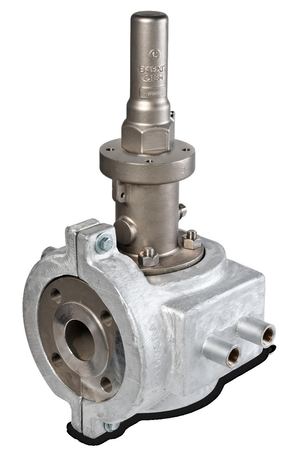
The Farris full nozzle pressure relief valve design (Fig 1) incorporates a nozzle shape to provide:
1. A high stable flow coefficient.
2. Greater strength to resist possible discharge piping strains.
Wrenching Provision
Figure No. 1
3. Wrenching provisions on raised face nozzles where they will not interfere with the flow path.
The superior design allows easy maintenance by simplifying nozzle removal and assembly.
Balanced Bellows Design
Both the Farris BalanSeal balanced bellows (Fig 2A) and the BalanSeal/ Piston pressure relief valve provide consistent capacity, set pressure and blowdown at elevated backpressure encountered when valves discharge into headers or where other devices produce variable backpressure in the relief manifold system. Nozzle can be removed from body with the blowdown ring attached.
The Farris BalanSeal design permits simple conversion of conventional construction valves to BalanSeal balanced bellows construction by adding a bellows and bellows gasket for orifice sizes “F” through “Z”.
The “D” and “E” orifices are available with balanced bellows through the class 600 inlet, with higher class valves available in an unbalanced bellows design (Fig 2B). The unbalanced bellows is used for corrosion isolation applications, and can also be used where constant backpressure is encountered. Spring setting compensation is made for constant backpressure applications.
% of
% of
Approx. Opening Pressure
Approx. Closing Pressure
% of Back Pressure
Balanced Farris Bellows
Figure No. 2A
Approx. Opening Pressure
Approx. Closing Pressure
% of Back Pressure
Unbalanced Bellows
Figure No. 2B
2600 Series Construction
Resistance to Discharge Piping Strains
For most pressure relief valves, and particularly for those from which the discharge must be piped away to a remote location, it is almost impossible to keep piping strains away from the valve. The superior Farris pressure relief valve design incorporates several features which allow this valve to take a maximum amount of piping strain without hampering the functional characteristics of the valve or contributing to serious leakage.
1. The threaded connection between the valve nozzle and the valve inlet flange is located low in the flange so that any distortion which may take place at the inlet neck of the body is not transmitted to the valve nozzle. This eliminates the effect of the distortion on the nozzle seating surface and the subsequent serious leakage through the valve (Fig 3).
2. The accurate guiding in the Farris design, using the double universal ball joint construction above and below the sleeve guide, will allow the disc seat to align itself positively with the nozzle seat in cases where the discharge piping strains cannot be avoided and have forced the upper portion of the valve out of exact alignment (Fig 5 & 6).
3. The superior strength built into the body of the Farris pressure relief valve to resist these discharge piping strains materially reduces the deflection and distortion in the valve and reduces the leakage encountered, when at times discharge piping strains become excessive.
In spite of these features, however, it is advisable to minimize the discharge piping strain on any pressure relief valve. It is our recommendation that piping engineers eliminate these discharge piping strains as much as possible under all operating conditions.
Isolation of Bonnet Spring Chamber
The Farris pressure relief valve huddling chamber is engineered to extract the flow forces required to overcome the force of the spring as well as the forces resulting from the body and bonnet pressure when the valve is open. In other designs, the use of eductor tubes, venting the guide directly into the valve body, or other techniques are used in an attempt to keep the huddling chamber or body pressure away from the topside of the disc to obtain full lift and capacity. These designs may have undesirable effects on valve performance, life and maintenance. Special attention should be given in the following cases:
1. High Temperature In Farris pressure relief valves on high temperature service, there is no induced or forced flow of the hot lading fluid into the bonnet spring chamber, so relaxation of the spring due to high temperature does not occur as rapidly as it does in other valve designs. As a result, blowdown in the Farris valve is stabilized for longer flowing periods than in competitive designs.
Threaded connection of nozzle located in inlet flange to avoid distortion on the nozzle seating surface.
No. 3
If connected to a closed system, specific care should be taken to keep piping strains away from the pressure relief valve under all conditions of process operation.
Cap may be required for weather protection
Support to resist weight and reaction forces
Pressure relief valve
Vessel
Long radius elbow
No. 4
2. Corrosive Service In Farris pressure relief valves on corrosive service, there is no induced or forced flow of the corrosive lading fluid past the guiding surfaces during valve operation. This reduces the corrosive effect of the lading fluid on the guiding surfaces and valve spring, so lowering the frequency of galling and spring failure with the accompanying reduction of maintenance costs and unscheduled down time.
3. Dirty Service Where small foreign particles can be carried in the gas or vapor stream, there is no induced or forced flow in the Farris design carrying these small particles between the guiding surfaces. Galling of the guide surfaces, which frequently causes the valve to “hang” or “freeze” in either an open or closed position, is eliminated.
The Farris design avoids all these difficulties by discharging directly from the huddling chamber into the valve body without inducing flow past the guiding surfaces into the spring chamber or forcing flow past the guiding surfaces because of the large pressure drop between the huddling chamber and the valve body.
Figure
Figure
2600 Series Metallurgy
Integral Sleeve Guide
The Farris pressure relief valve design incorporates an integral sleeve guide (Fig 5), assuring continual positive alignment after the part has been manufactured, and including the same high corrosion resistant properties in the guide flange that are present in the sleeve portion of the guide. The sleeve guide is extended above the top of the guide flange, minimizing the possibility of corrosive or other foreign particles washing onto the guiding surfaces when the valve is relieving or when it is “breathing” as a result of atmospheric temperature changes. Openings are provided in the guide flange to allow these solid particles to leave the bonnet, preventing them from passing between the guiding surfaces and causing galling.
Tightness
In a spring loaded pressure relief valve, the force exerted by the system pressure under the valve disc approaches the opposing spring force on top of the valve disc as the system operating pressure nears the set pressure of the valve. Since the operating pressure of the system is often 90% of the valve set pressure, the differential force holding the seats together is quite small.
There are several factors which affect the tightness of the spring loaded pressure relief valve, including alignment, disc strength, thermal distortion, and preparation of seating surfaces. The Farris valve is engineered for exceptional tightness because of positive alignment, a high strength disc design, the elimination of thermal distortion and optimum seating surface finish.
Positive Alignment Using the double universal joint, 2-1/2 to 1 guiding ratio, and self-aligning disc, positive alignment of internal parts is achieved. Misalignment is avoided, improving tightness and eliminating other undesirable effects such as long blowdown.
High Strength Disc Design In the Farris valve, the thickness of the selfaligning disc (Fig 6) is no greater than necessary; however, the same thickness is maintained for all catalog materials. For purposes of strength, the disc is strong enough in bending moment for all materials shown in the catalog. Valves constructed with hardened discs are exceptional in withstanding the effects of impact, an advantage where installation or process conditions may cause chatter.
Elimination of Thermal Distortion In a pressure relief valve, especially on high or low temperature service, a single large disc, with its top surface exposed to atmospheric temperature when the valve is closed, has a temperature gradient between the surface contacted by the lading fluid and the surface contacted by the ambient temperature in the valve body or bonnet. This temperature gradient induces thermal stresses in a heavy disc that can cause deformation of the seating surfaces and consequent leakage of the valve.
The Farris self-aligning disc is essentially encased in a disc holder with contact at only one central point, so that the conduction or convection of heat around the disc is quite low. As a result, the thermal stresses at the seating surface practically disappear. This gives further assurance of tightness over the range of temperatures used in various operations.
Optimum Seating Surface Finish Seat surfaces are machine lapped and polished to produce flatness (as measured with optical flats) that deviates less than eleven millionths of an inch from a true plane, with a surface finish of five micro inches or less. Regardless of the seating surfaces, maximum tightness will not be achieved unless positive alignment and elimination of thermal distortion are integral design features of the valve.
Integral Sleeve Guide Figure No. 5
High Strength Disc Figure No. 6
Positive connection of parts
All stainless steel stem construction
Drainage openings
Self-aligning disc
Positive connection of parts
Sleeve guide
Sleeve guide flange
2600 Series Operation
All Stainless Steel Stem Construction
The Farris pressure relief valve design features an all stainless steel stem. This construction cost-effectively eliminates dangerous sticking due to galvanic corrosion at the upper guiding point in the spring adjusting screw. The careful design of this upper bearing also ensures proper alignment and optimum freedom from galling and erratic popping.
Positive Connection of Parts
The Farris design incorporates a positive connection between the valve stem and the stem retainer as well as between the disc and disc holder (Fig 7). These connections are made with a male threaded head which threads into a portion of a female socket through which it drops free into an undercut chamber to make bearing contact on a spherical surface. This allows complete freedom of action for alignment purposes while retaining the positive connection of the threads. It also eliminates the need to use snap ring connections which, in some cases, are not sufficiently positive during valve operations and may be inadvertently left out during maintenance.
The Farris two-piece design of disc holder and stem retainer features a positive locking device called the disc holder lock screw. Any attempt to disassemble these parts causes the lock screw to lock tighter, unless first disengaged. The lock screw provides a positive lock between these two parts that makes them equivalent to a single part but without the associated disadvantages. The two-piece assembly allows conversion to bellows construction at a minimal investment. The two-piece design also allows the stem retainer to be constructed of less corrosion-resistant material than the disc holder, when a bellows is installed to isolate the moving parts. When maintenance requires parts replacement, the entire assembly will not need replacement if only one piece is damaged.
Convertibility of Design
The Farris pressure relief valve is available as a conventional valve and as a BalanSeal (balanced bellows) valve. The conversion of this valve from conventional to BalanSeal, or vice versa, requires only the addition or removal of the balanced bellows and bellows gasket in the valve, and the coincidental removal or replacement of a pipe plug in the valve bonnet vent. No other parts are required and all other parts are completely interchangeable. This unique feature is offered in orifices “F” through “T”.
In addition, the bonnet of the valve is constructed so that all valves can be equipped with a plain screwed cap, bolted cap, an open lever or packed lifting lever without changing any other valve parts or fully disassembling the valve.
Body and Bonnet of Equal Materials
Although the Farris pressure relief valve does not induce circulation of the lading fluid through the bonnet, the bonnet and the valve body are made of the same high quality steel. It is important that both the body and bonnet be made of materials suitable for the service in which the valve will be used, especially in the case of high temperature services.
2600 Series Operation
Steam Jacketing for Better Heat Transfer
In modern process plants, it is necessary to keep some valves and lines warm at all times to avoid solidification of the lading fluid and to guarantee the safety of equipment. Farris offers a steam jacket (Fig 8) to substantially increase the rate of heat transfer into the valve and, at the same time, simplify the problem of removing or dismantling the valve for maintenance. This design offers a separate two-piece jacket that installs on a standard valve body. See details on page 74.
Simple, Accurate Adjustments
The single blowdown ring construction of the Farris pressure relief valve allows simple shop or field setting, something not possible with multiple ring valve types.
In most process plants, it is not possible or economical to test the pressure relief valve in place on the process equipment, so the valve is tested while mounted on a maintenance shop test stand where the pressure and volume for testing are often limited. With the Farris design, the single blowdown ring is adjusted in the maintenance shop so that the set pressure point can be observed. After the set pressure is established, the blowdown ring is adjusted to a lower empirically predetermined or field established position depending on set pressure, size and lading fluid (Figs 9A, 9B). Blowdown ring settings and test equipment recommendations are detailed in maintenance manuals published by Farris Engineering.
Interchangeability of Parts
In the Farris pressure relief valve design, maximum interchangeability of parts is maintained in order to reduce the number of spare parts needed and keep spare parts inventories to a minimum.
Blowdown Ring Adjustment for Set Pressure Test
Figure No. 9A
Blowdown Ring Adjustment for Service Operation – Vapors
Figure No. 9B
Steam Jacketed Body
Figure No. 8
General Technical Information
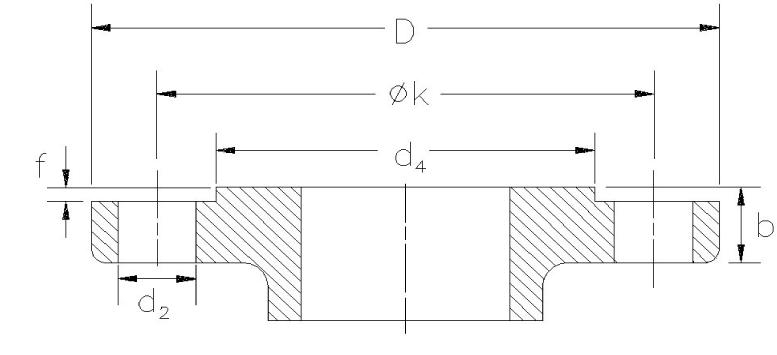
Standard Flanged Connections
1. All steel raised face flanges are supplied with a serrated spiral finish with 45 to 55 grooves per inch and a finish between 125 and 160 AARH.
2. All ring joint flanged facings are supplied for octagonal or oval gaskets.
3. Facings other than raised face or large male can be supplied at additional cost.
4. Flange ratings that conform to ASME B16.5 are indicated on the orifice selection table. Heavier outlet flanges can be supplied at additional cost. For flange dimensions, see ASME Dimension Table, page 80.
5. Drilling of all flanges always straddles the valve center line.
Valve Trim
Trim is a term that generally refers to internal parts of a pressure relief valve. Unless noted, valve trim in a Farris pressure relief valve specifically includes the nozzle and disc only. Standard bills of materials for all 2600 Series valves are located on pages 15 and 16. For low temperature and corrosive service materials, see pages 20 through 24. If other than standard trim or metallurgy is required, this must be specified.
Differential Between Operating and Set Pressure
For best performance in process applications, we recommend pressure relief valves be set to open at a minimum of 10% or 25 psig above the operating pressure. A suitable margin above the operating pressure should be provided in order to prevent any unintended operation of the pressure relief valve. Refer to VIII, Paragraph M-10, Pressure Differentials for Pressure Relief Valves.
In the case of pump and compressor discharge lines, a greater differential is recommended if possible, since pulsations within the system can result in faulty valve operation. Consequently, the pressure relief valve should be set as high above the discharge line pressure as possible.
Set Pressure Compensation for Temperature
An increase in temperature causes a reduction of valve set pressure as a result of the direct effect of temperature on the spring and expansion of body and bonnet which reduces spring loading. Since pressure relief valves are invariably tested at atmospheric temperature, it is customary to adjust the set pressure at ambient conditions to compensate for higher operating temperatures as indicated in the following table.
All Service Fluids
-450° F to 300° F None
301°
Steam service valves are tested on steam by the manufacturer and require no additional temperature compensation. Where the set pressure is above the production steam test facility limits, Section XIII steam valves may be tested on air. When steam valves are tested on air, compensation shown in the All Service Fluids Table should be used.
Low Pressure Settings
Low set pressure limits are indicated in the following table. These limits apply to both metal-to-metal and O-ring seat construction. Low pressure settings may be governed by valve design and performance and/or Code application limits. Pressure vessels having operating pressures not exceeding 15 psig are not considered within the scope of the ASME Code, Section VIII. Accordingly, pressure relief valve requirements for such applications are governed by other codes and standards that should be consulted.
The sizing equations for compressible fluids provided herein are valid for sonic flow conditions and should not be used to size pressure relief valves for applications in which subsonic (below 15 psig) flow conditions may exist. Low pressure applications can be reviewed by the factory and special valves provided to meet those requirements.
2600
2600S
2600L
2600M Conventional 15
2600
2600S
2600L
2600M
2600 Bal/Piston
BalanSeal BalanSeal/ Piston 151
1Low set pressure limit for “D” and “E” orifice BalanSeal (balanced bellows) valves are 50 psig and 25 psig respectively.
Definitions
Safety Valve – an automatic pressure relieving device actuated by the static pressure upstream of the valve, and characterized by rapid full opening or pop action. Used for steam, gas or vapor service.
Relief Valve – an automatic pressure relieving device actuated by the static pressure upstream of the valve, which opens in proportion to the increase in pressure over the opening pressure.
Safety Relief Valve – an automatic pressure actuated relieving device suitable for use as either a safety or relief valve, depending on the application.
Pressure Relief Valve – a pressure relief device designed to re-close and prevent the further flow of fluid after normal conditions have been restored.
Set Pressure – in pounds per square inch gage, the inlet pressure at which the pressure relief valve is adjusted to open under service conditions. In a safety or safety relief valve in gas, vapor or steam service, the set pressure is the inlet pressure at which the valve pops under service conditions. In a relief or safety relief valve in liquid service, the set pressure is the inlet pressure at which the first steady steam flows from the valve perpendicular to the outlet.
Differential Set Pressure – the pressure differential, in pounds per square inch between the set pressure and the constant superimposed back pressure. It is applicable only when a conventional type safety relief valve is being used in service against a constant superimposed back pressure.
Cold Differential Test Pressure – in pounds per square inch gage is the inlet static pressure at which the pressure relief valve is adjusted to open on the test stand. This pressure includes the corrections for service conditions of back pressure or temperature, or both.
Operating Pressure – the pressure, in pounds per square inch gage to which the vessel is usually subjected in service. A vessel is usually designed for a maximum allowable working pressure, in pounds per square inch gage, which will provide a suitable margin above the operating pressure in order to prevent any undesirable operation of the relief device. It is suggested that this margin be as great as possible consistent with economical vessel and other equipment design, system operation and the performance characteristics of the pressure relieving device.
Maximum Allowable Working Pressure – the maximum gage pressure permissible in the top of a completed vessel in its operating position for a designated temperature. This pressure is based on calculations for each element in a vessel using nominal thicknesses, exclusive of allowances for corrosion and thicknesses required for loadings other than pressure. It is the basis for the pressure setting of the pressure relieving devices protecting the vessel. The design pressure may be used in place of maximum allowable working pressure in cases where calculations are not made to determine the value of the latter.
Overpressure – a pressure increase over the set pressure of a pressure relief valve, usually expressed as a percentage of the set pressure.
Accumulation – the pressure increase over the maximum allowable working pressure of the vessel during discharge through the pressure relief valve, expressed as a percent of that pressure or in pounds per square inch.
Blowdown – the difference between actual set pressure of a pressure relief valve and actual reseating pressure, expressed as a percentage of set pressure or in pressure units.
Lift – the actual travel of the disc away from closed position when a valve is relieving.
Back Pressure – the static pressure existing at the outlet of a pressure relief device due to pressure in the discharge system.
Superimposed Back Pressure – the static pressure existing at the outlet of a pressure relief device at the time the device is required to operate. It is the result of pressure in the discharge system from other sources when the valve is closed. Superimposed back pressure can be constant, variable or both:
- Constant Superimposed Back Pressure – back pressure which does not change appreciably under any condition of operation whether the pressure relief valve is closed or open.
- Variable Superimposed Back Pressure – the pressure existing at the outlet of a pressure relief device, which does not remain constant when the pressure relief valve is closed.
Built-Up Back Pressure – pressure existing at the outlet of a pressure relief device occasioned by the flow through that particular device into a discharging system.
Type Numbering System
Our type numbering system simplifies the selection and specifying of Farris pressure relief valves because the digits that comprise a specific type number have a distinct significance. The digits describe the basic valve series, orifice, seat and internal construction, inlet temperature range, body, bonnet and spring material, inlet flange class and code liquid design.
Prefix 26 D A 1 2
Designates high pressure versions. Used for “Q”, “R”, “T”, & “U” orifices only.
B BalanSeal construction
C Conventional with O-ring seat pressure seal
D BalanSeal with O-ring seat pressure seal
E BalanSeal with auxiliary balancing piston
F BalanSeal with auxiliary balancing piston and O-ring seat pressure seal
T PTFE seat, conventional (for D-K only)
U PTFE seat, BalanSeal (for D-K only)
* The “U” through “Z” orifices are not API Standard Sizes
Ordering Information
To process your order properly and promptly, please specify the following:
1. Quantity*
2. Inlet and outlet size
3. Farris type number*
4. Inlet and outlet flange class and facing
5. Materials of construction, if other than standard
6. O-ring seat pressure seal material, if required
7. Set pressure*
8. Maximum inlet temperature*
9. Allowable overpressure*
10. Fluid and fluid state*
11. Back pressure, superimposed constant and/or variable and built-up*
12. Required capacity*
13. Accessories
(a) Bolted cap, open or packed lever
(b) Test gag
(c) Remoter
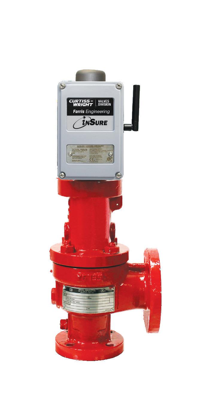
(d) inSure Monitor
1 -20 to 800***
to
4* 1001 to 1200 Consult Factory 5* 1201 to 1500 Consult Factory 1 -21 to -75 Use “S3” Trim Options 1 -76 to -450 Use “S4” Trim Options **
* Temperature ranges 4 and 5 are beyond the scope of this catalog. Consult the Factory.
** Temperature range illustrated to designate low temperature use. The “S3” & “S4” trim can be used at high temperatures. See Page 21.
*** LB and LC options limited to 650°F max temperature.
14. Code requirements, if any
15. Physical properties of fluid (molecular weight, specific gravity, etc.)
*As a customer service, we verify your selection and sizing. If you want this service, you must include this information.
Parts Replacement
Valves – If an exact replacement valve is required, then the valve type, size and serial number must be specified to ensure proper dimensions and material being supplied. If a specific valve is obsolete, a recommendation of the current equivalent will be made if possible.
Spare Parts – When ordering parts, use part names as listed in the bills of materials. Specify valve type, size and serial number. If the serial number is not available, the original Farris factory order number will help us supply the proper part and material.
Springs – Order as an assembly to include spring with upper and lower spring buttons. Specify valve type, size, serial number, set pressure and backpressure, if any.
Note: If valve modification or set pressure changes are required, consideration must be given to correct the nameplate and other data.
Construction (If applicable)
A Expanded API sizes: air, steam and gas service*
B Expanded API sizes: liquid, air, steam and gas service*
C Expanded API sizes: ASME Code Section VIII exposed spring design*
D Valve suitable for heat transfer service-vapor
E Valve suitable for heat transfer service-liquid
F Expanded API size valves suitable for heat transfer service-vapor*
G Expanded API size valves suitable for heat transfer service-liquid*
L ASME Code certified for liquid, air, steam and gas service.**
M ASME Code Certified for multiple-media, API sizes, CC 2787
P ASME Code Certified for multiple-media, CC 2787, former 2 1/2" flange sizes
S ASME Code Section VIII exposed spring design
* Letter suffixes for expanded API sizes where 2-1/2" inlet or outlet has been replaced by 3" size.
** Certified as non-adjustable blowdown
0 Special Facings2
1 Raised Face (125 to 160 AARH)
2 Large Female
3 Small Male
4 Small Female
5 Large Tongue
6 Large Groove
7 Small Tongue
8 Small Groove
9 Ring Joint (octagonal), ASME Std.
H 63-83 AARH Smooth Finish RF
Although not applicable to the Inlet facing only, the following first digit letters are also used:
J 63 to 83 AARH (outlet only)
K 63 to 83 AARH (inlet & outlet)
X Special Welded Connections3
Materials for Corrosive Service
Designation
/S3
/S4
2 Screwed Cap
3 Bolted Cap
4 Packed Lever
7 Open Lever
8 Remoter (with Packed Lever)
H inSure monitor wirelessHART®
M inSure® Monitor, wired 4-20mA
S inSure® Monitor, wireless ISA100TM 0 Without Gag 1 With Gag
“Materials for Corrosive Service” Table below. SP1 RL
Material Description Body,
&
SS
/H1 Standard Hastelloy C Standard Standard
Spring, 316 SS Buttons
/H2 Standard Hastelloy C Hastelloy C & Monel Chrome Alloy Spring, 316 SS Buttons
/H3 Hastelloy C® Hastelloy C Hastelloy C Chrome Alloy Spring, 316 SS Buttons
/H4 Hastelloy C
Hastelloy C Hastelloy C Hastelloy C
/M1 Standard Monel Standard Standard
/M2 Standard Monel Monel Chrome Alloy Spring, 316 SS Buttons
/M3 Monel Monel Monel Chrome Alloy Spring, 316 SS Buttons
/N1 Carbon Steel (NACE) 316 SS (NACE) 316 SS4 Inconel Spring, 316 SS Buttons
/LB SA-352 Gr. LCB (Cap - 316 SS) 316 SS 316 SS Standard
/LC SA-352 Gr. LCC (Cap - 316 SS) 316 SS 316 SS Standard
/N4 316 SS (NACE) 316 SS (NACE) 316 SS Inconel Spring, 316 SS Buttons
1 Special trim or connection types not covered by other type number designations require "/SP" added to the type number. Example: 26HA10-120/SP.
2 Special inlet facings not covered by other inlet facing designations such as lens joint inlet or non-standard nozzle finishes.
3 Designates welded inlet connections including butt-weld, socket weld and high pressure Grayloc® (hub style) connections.
4 Spring adjusting screw is supplied in standard precipitation hardened (17-4 Ph) stainless steel.
For special non stainless trim in compliance with NACE Standards add "N" to the material suffix. Example: 26HB12-120/M4N.
Duplex stainless trim options available on application in standard and super duplex alloys. Consult the factory.
For corrosive and low temperature materials, see pages 20 through 24.
For open and packed lever materials and test gags, see accessories on pages 72.
For capacities, see pages 42-45 U.S. Units, 60-63 Metric Units.
For dimensions and weights, see pages 75-78.
For ASME Certified liquid service use the 2600L Series as illustrated on page 17.
1 Applies to type numbers 26( ) A10 thru 26( ) A16.
2 Applies to type numbers 26( ) A32 thru 26( ) A36.
2600/2600L/2600M Series BalanSeal
Parentheses in type number indicate orifice designation, as in 26FA10.
For corrosive and low temperature materials, see pages 20 through 24.
For open and packed lever materials and test gags, see accessories on pages 72.
For capacities, see pages 42-45 U.S. Units, 60-63 Metric Units.
For dimensions and weights, see pages 75-78.
For ASME Certified liquid service use the 2600L Series as illustrated on page 17.
1 Applies to type numbers 26( )B10 through 26( )B16.
2Applies to type numbers 26( )B32 through 26( )B36.
2600/2600L/2600M
Series Certified Design
2600M Series Certified Design for Multi-Media
The 2600M Series multi-media service relief valves provide inventory flexibility and superior performance in two-phase flows. With this option, the same relief valve can be set on one media and have both air/vapor and liquid capacities stamped on the nameplate without set point adjustments, as allowed by ASME Code Case 2787.
This allows customers to simplify their install base by ordering one valve that can be used in multiple medias. ASME Code Case 2787 allows multiple marking of nameplate capacities for pressure relief valves. Manufacturers or assemblers with UV designation may place more than one certified capacity on the valve nameplate provided the valve has been certified for each media with no adjustments and within tolerance requirements in Section XIII.
The type number is differentiated from the existing 2600 Series design by adding the appropriate Special Construction designator as referenced in the Type Numbering System. Add the "M" designator for all API sizes, and "P" for former API 2 1/2" flange sizes. Example: 26DA10M-120.
This option is available for all conventional, BalanSeal, or O-ring seat 2600 series valves with orifice sizes D through U.
2600L Series Certified Design for Liquid
The 2600L Series liquid relief valves are for use on ASME Section VIII Code applications and offer a superior valve with greater capacity at 10% overpressure than the traditional 2600 Series.
The 2600L Series complements a full line of pressure relief valves in orifices “D” through “U” and "W" to meet the ASME Code requirements for incompressible fluid services. The Code stamped construction requires liquid relief valves that have been capacity certified on water at 10% overpressure to carry the ASME UV and National Board NB symbols.
For compressible fluid services, the standard 2600 Series should be used. Liquid service applications that do not require the use of Code stamped liquid relief valves can still be satisfied with the standard 2600 series line. In most cases the standard 2600 should only be used in liquid service where an existing installation pipe size / orifice combination does not match the 2600L design.
The type number is differentiated from the existing 2600 Series design by adding the letter “L” as a suffix. The letter “L” is used to specify all liquid trim type numbers and always appears in the seventh position of the type number, just before the three-digit option code for inlet facing/cap construction/test gag. Example: 26GA10L-120.
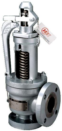
2600S Series Exposed Spring
The 2600S Series safety valves with exposed springs represent an enhancement of the standard 2600 Series and are designed to offer improved performance in steam service. They are built in conformance to Section VIII and XIII of the ASME Code and have capacities certified at 10% overpressure by the National Board of Boiler and Pressure Vessel Inspectors. Series 2600S is available in the same “D” through “Z” orifices and flange classes as the standard 2600 Series, and have the same center-to-face dimensions (API Std. 526).
In steam service, you can encounter galling of the guiding surfaces. To minimize this problem, the guide and stem retainer are made from different materials: 316 SS stainless steel for the guide and hardened stainless steel for the stem retainer. Since the open bonnet is made from a standard 2600 Series bonnet, all other parts are identical to the 2600 Series to provide maximum interchangeability of parts and to reduce inventory costs.
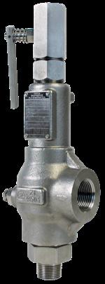
An open lifting lever, required by ASME Code for steam and air service, is standard with the 2600S Series. Chrome alloy springs are used to 1000° F. They can also be used on air service or on other clean gases. Most other 2600 Series options can be supplied, including O-ring seats and bellows. For weather protection of the spring, use the standard 2600 vapor service valve with open lever.
The type number is differentiated from the 2600 Series by the addition of the suffix letter “S” in the seventh digit of the type number. Example: 26JA10S-170.
Built in conformance to ASME Code Section VIII & XIII, capacity certified by National Board
2600/2600L Balanced Piston Design
Balanced Bellows with Auxiliary Balancing Piston
Under back pressure conditions, rupture of the bellows can cause an increase in set pressure of the pressure relief valve. Consistent with safety, Farris Engineering offers a BalanSeal/piston design to compensate for a broken or ruptured bellows. The valve features a piston guide that has an inside diameter equal to the average diameter of the bellows convolutions.
If the bellows fails, the effect of the back pressure is nullified by the use of the piston. Since there is a slight diametrical clearance between the piston and the guide, a small amount of lading fluid is permitted to pass through the bonnet vent, indicating a bellows rupture. Although the valve will continue to function as a Farris bellows pressure relief valve, the damaged bellows should be replaced to avoid further product loss.
When the proper orifice and corresponding letter designation have been determined, refer to the selection charts and choose the conventional pressure and temperature required. Sizes, set pressure, back pressure, temperature ratings and capacity data are the same as the BalanSeal construction.
To convert the conventional valve type number to the catalog number for balanced bellows valve with auxiliary balancing piston, insert the letter “E” in place of “A”. Example: 26FA12-120 conventional valve becomes 26FE12-120.
2600 Series Heat Transfer Fluid Service
The inherent features of engineering design in the Farris nozzle pressure relief valve make it ideal for heat transfer fluid service. Heat transfer fluids form solid on relief to atmosphere and exhibit non-lubricating qualities. Consequently the valve requires the ultimate in tightness and perfect guiding beyond that of a valve used in other services.
The Farris design includes a 2-1/2 to 1 guiding ratio, self-aligning, flat, easily replaceable disc and double universal joint for exact alignment. These valves have been proven in thousands of installations and are accepted as the industry standard for heat transfer fluid service.
For additional protection against deposit build-up on the guiding surfaces, a BalanSeal bellows can be provided to isolate internal working parts.
All heat transfer fluid service valves receive particular attention in the Farris assembly and testing departments. Special lapping, gasketing and sealing compounds are used to assure maximum tightness for this hard-to-hold service.
2600 and 2600L Series Restricted Lift
The restricted lift option is a great solution for applications where a valve with standard orifice is oversized and more susceptible to chattering. The 2600 and 2600L are available with lift restricted below the normal certified lift necessary to achieve full flow. This option is orders with the -RL designator as noted in the Type Numbering System.
The lift restriction is achieved by the installation of a spacer between the stem retainer and the sleeve guide. This spacer physically limits the available lift and thus the actual capacity. The material of the spacer will match the material of the stem retainer.
In accordance with ASME Code Section XIII the restriction shall be no less than 30% of full rated lift or 0.08 in, whichever is greater.
Materials for Corrosive and Low Temperature Service
Standard materials of construction for corrosive service and low temperature service are listed on pages 21-24. Our selection of these materials is a result of many years of research in metallurgy and, while not all-inclusive, covers the most frequently used construction materials. In the case of a special application that requires materials not listed in this catalog, consult the factory.
Note that Farris Engineering cannot guarantee valve service life, as there are many factors that can affect the life of any material and that are beyond our control.
Corrosive Service. A pressure relief valve is not expected to operate frequently; therefore, standard materials should prove satisfactory. Where severe corrosive conditions exist, the nozzle and disc, which are always
exposed to the lading fluid, are available in more corrosive-resistant materials such as Monel (/M1) and Hastelloy C (/H1).
Where specific applications require complete internals to be more corrosion resistant due to frequent valve operation and where parts beyond the nozzle and disc are exposed to corrosive lading fluid, complete internals and the complete valve are available in 316 SS, Monel and Hastelloy (/S3, /S4, /N1, /N4, /M2, /M3, /M4, /H2, /H3, /H4, /LB, /LC).
Low Temperature Service. For low temperature applications, we offer LB (-50F), LC (-55F), S3 (-75F), and S4 (-450F) trim categories, depending on the degree of sub-zero temperatures involved. Materials cover special metallurgy to maintain adequate impact resistance on all stressed parts at sub-zero temperatures.
Spacer
Standard Material for Corrosive Service 316 SS1
Body
Bonnet
Cap, Plain Screwed
Disc
Nozzle
Disc Holder
Blowdown Ring
Sleeve Guide
Stem
Adj. Screw
Jam Nut (Spr. Adj. Scr.)
Blowdown Ring
Lock Screw
Lock Screw Stud
Stem Retainer
Bellows
Bellows Gasket
Cap Gasket
Bonnet Gasket
Body Gasket
Lock Screw Gasket
Hex. Nut (Lock Screw)
Disc Holder Lock Screw
Any part not specified is standard material.
To designate valves with Monel construction, add the appropriate suffix to the type number. Example: 26FA10-120 becomes 26FA10-120/M1.
For open and packed lever materials, see page 72.
1 Maximum set and back pressures for the S3 and S4 trim are equal to the 316
stainless valve limits shown in the Orifice Selection Tables and Valve Pressure Limits table.
Standard Material for Corrosive Service Monel
Part
Body
Bonnet
Cap, Plain Screwed
Any part not specified is standard material.
To designate valves with Monel construction, add the appropriate suffix to the type number. Example: 26FA10-120 becomes 26FA10-120/M1.
For open and packed lever materials, see page 72.
Monel and Inconel are registered trademarks of American Special Metals Corp. We reserve the right to substitute comparable materials from other manufacturers.
1 Maximum set pressures for M1 and M2 trim are equal to the Monel flange limits as shown on page 86. Consult the factory for higher pressures.
2 Maximum set and back pressures for the M3 and M4 trim are equal to the Monel valve limits as shown on page 86.
Standard Material for Corrosive Service Hastelloy C
Part Name
Body Hastelloy C Hastelloy C Hastelloy C Hastelloy C
Bonnet
Cap, Plain
Screwed
Hastelloy C Hastelloy C Hastelloy C Hastelloy C
Hastelloy C Hastelloy C Hastelloy C Hastelloy C
Disc Hastelloy C Hastelloy C Hastelloy C Hastelloy C Hastelloy C Hastelloy C Hastelloy C Hastelloy C
Nozzle Hastelloy C Hastelloy C Hastelloy C Hastelloy C Hastelloy C Hastelloy C Hastelloy C Hastelloy C
Disc Holder
Blowdown Ring
Sleeve Guide
Hastelloy C Hastelloy C Hastelloy C Hastelloy C Hastelloy C Hastelloy C
Hastelloy C Hastelloy C
Hastelloy C
Stem Monel
Spring Adj. Screw Monel
Jam Nut (Spring Adj. Screw) Monel
Lock Screw Stud
Stem Retainer
Bellows Gasket
Body Stud
Body Hex Nut
Cap Gasket
Bonnet Gasket
Body Gasket
Lock Screw Gasket
Hex Nut (Lock Screw)
Disc Holder Lock Screw
Pipe Plug (Bonnet)
Pipe Plug (Body)
Hastelloy C Hastelloy C Hastelloy C Hastelloy C
Hastelloy C Hastelloy C Hastelloy C Hastelloy C
Hastelloy C Hastelloy C Hastelloy C Hastelloy C
Hastelloy C Hastelloy C Hastelloy C Hastelloy C
Hastelloy C Hastelloy C Hastelloy C Hastelloy C
C
C
Any part not specified is standard material.
To designate valves with Hastelloy C construction, add the appropriate suffix to the type number. Example: 26FA10-120 becomes 26FA10-120/H1.
For open and packed lever materials, see page 71.
Back pressure limits for the H2, H3, and H4 BalanSeal and balanced piston valves are on application.
Hastelloy and Hastelloy C are registered trademarks of Haynes International, Inc. We reserve the right to substitute comparable materials from other manufacturers.
1 Maximum set pressures for H1 and H2 trim are equal to the carbon steel valves in the Selection Tables.
2 Maximum set and back pressures for the H3 and H4 trim are equal to the Hastelloy C valve limits shown on pages 84 and 85.
Pressure Relief Valves for Sour Gas Service NACE
MR0103 and MR0175/ISO 15156
NACE International (formerly The National Association of Corrosion Engineers) publishes two standards covering the use of equipment in environments containing H2S (Hydrogen Sulfide). The standards are: MR0103, Standard Material Requirements – Materials Resistant to Sulfide Stress Cracking in Corrosive Petroleum Refining Environments; and MR0175/ISO 15156, Petroleum and Natural Gas Industries – Materials for Use in H2S-Containing Environments in Oil and Gas Production.
The material requirements of the NACE Standards have resulted in various constructions. 2600 Series valves constructed of standard carbon steel (SA216 Grade WCB) and 316 SS (SA351 Grade CF8M or SA479 Type 316 SS) will be dual certified to NACE MR0103 and NACE MR0175/ISO 15156. For non-standard materials, Farris Engineering will have to review the materials on a case-by-case basis to determine NACE compliance.
The customer must decide whether the application requires a valve in compliance with NACE standards. Farris Engineering is responsible for supplying materials in compliance with the applicable NACE specification. As part of the order requirement, Farris will verify that material hardness values are in compliance with the NACE standard on the body, bonnet, nozzle and disc as applicable. Additionally, we will offer bolting and springs (for conventional and pilot operated valves only) in compliance with NACE specifications.
To specify a valve with materials compliant to NACE specifications, add the suffix /N1 or /N4 to the standard type number. Example: 26LB12-120/N1.
Cap, Plain Screwed
Disc Holder
Blowdown Ring
Sleeve Guide
Stem
Spring Adj. Screw
Jam Nut (Spr. Adj. Scr.)
Blowdown Ring
Lock Screw
Lock Screw Stud
Stem Retainer
Bellows
Bellows Gasket
Spring Button
Spring
Cap Gasket
Bonnet Gasket
Body Gasket
Lock Screw Gasket
Hex. Nut (Lock Screw)
Disc Holder Lock Screw
Pipe Plug (Bonnet)
Pipe Plug (Body)
Any part not specified is standard material. For N1 standard valve, see pages 15-16. For N4, see page 21 S4 trim. For open and packed lever materials, see page 71.
For a valve with complete Inconel bellows, use “N1/SP” type number suffix. Example: 26JB10-120/N1/SP. For a valve in complete stainless steel, add “N4” to suffix. Example: 26HB10-120/N4. For optional complete Inconel bellows, add “N4/SP”. Example: 26HB10-120/N4/SP.
Farris O-Ring Seat Pressure Seal for Conventional or BalanSeal
The O-ring seat pressure seal minimizes leakage and costly product loss as well as reduces downtime and maintenance on troublesome applications such as:
• Operation too close to set pressure
• Light, hard-to-hold fluids
• Entrained foreign particles and solids
• Vibratory applications
• Corrosive fluids
• Nozzle icing conditions
• Discharge piping strains
Recognizing the need for a resilient seat in a pressure relief valve for extreme tightness, Farris Engineering first produced an O-ring seat in early 1950. The O-ring design received and continues to receive phenomenal acceptance and use because it makes possible complete tightness at pressures much closer to valve set pressure. This tightness is not possible with the standard metal-to-metal seat.
The present Farris O-ring seat seal permits set pressure as high as 1500 psig. Equally important, the spring load is carried solely by the metal-tometal portion of the seat with the O-ring becoming a pressure seal within its recessed chamber, assuring maximum tightness.
The O-ring seat seal option is available for the 2600/2600L/2600S Series of flanged pressure relief valves in the conventional, BalanSeal, and BalanSeal/piston constructions. Refer to the Orifice Selection Tables. Substitute a “C” for the fourth digit “A” in the type number for the conventional valve, a “D” for the fourth digit “B” in the type number for a BalanSeal valve, and an “F” for the fourth digit in the type number for the BalanSeal/piston construction when an O-ring seat seal is required. Valves with Teflon seat seals are available on application.
The same type number changes apply to the 2600L Series. Examples:
26FA10 becomes 26FC10 (conventional).
26FB10 becomes 26FD10 (BalanSeal).
26FA10L becomes 26FC10L (conventional–liquid ser vice).
26FE10L becomes 26FF10L (BalanSeal/piston–liquid ser vice).
The set pressure limits of the conventional, BalanSeal, and BalanSeal/ piston valves covered in the Selection Tables are the same for the O-ring design in all type numbers and orifices with the class 150, 300, and 600 inlet flanges. Above class 600 inlet flanges, 1500 psig is the limit for the O-ring design, not the conventional limit shown in the Selection Charts and Tables. Refer to the O-ring Material Selection Table for temperature and pressure ratings of the various elastomeric O-ring materials available.
O-ring Detail D-K Orifice
O-ring Detail L-U Orifice
Why use an O-ring seat pressure seal?
In the normal operation of a pressure relief valve, the disc must lift off the nozzle very slightly to simmer, allowing pressure build-up within the secondary orifice (huddling chamber), causing the valve to pop fully open. Simmering occurs many times in the process industries where, as a result of process changes, minor upsets, etc., operating pressure fluctuates higher than normal, causing pressure relief valves to simmer but not fully open. This can cause serious misalignment in the valve, and after the pressure drops, the valve will very often continue to leak below the normal operating pressure. The leaking can be overcome by actually popping the valve, but sometimes this is not possible. Use of a Farris O-ring seat pressure seal will always correct this problem.
Frequently operating pressures are too close to valve set pressures. As the operating pressure nears the set pressure, seat loading is diminished, reducing the force that affects tightness. The Farris O-ring seat pressure seal ensures that tightness is achieved at relatively higher operating pressures, much more so than with metal-to-metal or other soft seat pressure relief valves.
On light, hard-to-hold fluids such as hydrogen, helium, light hydrocarbon, anhydrous ammonia, and others, metal-to-metal seats are often penetrated, causing leakage problems. The Farris O -ring seat pressure seal overcomes leakage on these hard-to-hold fluids.
In applications where heavy vibrations occur such as barges, tankers, pumps, and compressors, leakage of metal-to-metal seats develops. This occurs because, as the set pressure nears, the spring force is equalized and the vibration reduces the effect of seat loading, causing leakage. The Farris O-ring seat pressure seal maintains tightness because the spring force is not a factor in the tightness of the O-ring design.
Where occasional minute foreign particles are carried in the flowing medium, metal-to-metal seats are usually marred or scratched when the valve is blowing. This creates leakage problems after the valve closes.
The Farris O-ring seat pressure seal absorbs the impact of these particles without damage, and eliminates disc separation from the mating metal seating surface on the nozzle as the valve closes. This reduces the incidence of leakage on most process units. When necessary, simply replace the Farris O-ring to maintain tightness.
Due to corrosion, metal-to-metal seats can eventually leak. With the proper selection of the Farris O-ring seat pressure seal, tightness can be improved and maintained.
Nozzle icing results from the refrigerant effect of the flowing media when a valve relieves. Ice actually forms on the seat, causing leakage. The Farris O-ring seat pressure seal reduces this type of leakage.
O-RING MATERIAL SELECTION TABLE
FKM (VitonTM) -20 to 450 15 to 1500
Ethylene Propylene 0 to 350 15 to 1500
NBR (Buna N) 0 to 200 15 to 1500
Silicone -150 to 450 15 to 1500
Kalrez -20 to 550 15 to 1500 Neoprene -45 to 300 15 to 1500
Soft Goods Disclaimer
When selecting O-ring materials please note the following:
• The above selections are based on providing an appropriate compound to meet the pressure and temperature requirements indicated.
• Final O-ring selection should be chemically compatible with the process fluid.
• Selection of the proper O-ring material is the responsibility of the customer.
• We reserve the right to substitute comparable FKM materials
Standard seat tightness for O-ring valves is no bubbles at 90% of set pressure for both conventional and bellows valves. At set pressures of 50 psig and below, leakage test shall be made at 5 psig below set pressure.
Ethylene Propylene is acceptable for steam service up to 350 ºF.
PTFE seat seals available on an application basis. Consult the factory.
Refer to MS-02 for durometer required based on temperature and set pressure.
26DA10/S3 26DA11/S3 26DA12/S3 26DA13/S3 26DA14/S3
26DA10/S4
26DA11/S4
26DA12/S4
26DA13/S4
26DA14/S4
26DA15/S4
26DA16A/S4
26DB10/S4
26DB11/S4
26DB12/S4 26DB13/S4
The type numbers shown on the selection chart indicate conventional valves. For BalanSeal, O-ring construction, balanced piston design and other valve options, see the Type Numbering System.
Outlet pressure for temperatures above 1000°F shall not exceed the rating in ASME B16.5. For applications above 1000°F, consult the factory.
E Orifice
26EA10/S3
26EA11/S3
26EA12/S3
26EA13/S3
26EA14/S3
26EA15/S3 26EA16A/S3
26EA10/S4
26EA11/S4
26EA12/S4
26EA13/S4
26EA14/S4
26EA15/S4
26EA16A/S4
26EB10/S4
26EB11/S4
26EB12/S4 26EB13/S4
The type numbers shown on the selection chart indicate conventional valves. For BalanSeal, O-ring construction, balanced piston design and other valve options, see the Type Numbering System.
Outlet pressure for temperatures above 1000°F shall not exceed the rating in ASME B16.5.
For applications above 1000°F, consult the factory.
G Orifice
26GA10A/S3
26GA11A/S3
26GA12A/S3
26GA13A/S3
26GA14A/S3
26GA15/S3
26GA16/S3
26GA10A/S4
26GA11A/S4
26GA12A/S4
26GA13A/S4
26GA14A/S4
26GA15/S4
26GA16/S4
26GB10A/S3
26GB11A/S3
26GB12A/S3
26GB13A/S3
26GB14A/S3
26GB15/S3 26GB16/S3
26GB10A/S4
26GB11A/S4
26GB12A/S4
26GB13A/S4
26GB14A/S4
26GB15/S4
26GB16/S4
Selection Chart
The type numbers shown on the selection chart indicate conventional valves. For BalanSeal, O-ring construction, balanced piston design and other valve options, see the Type Numbering System.
Outlet pressure for temperatures above 1000°F shall not exceed the rating in ASME B16.5.
For applications above 1000°F, consult the factory.
H Orifice
26HA10/S3
26HA11/S3
Selection
Chart
The type numbers shown on the selection chart indicate conventional valves. For BalanSeal, O-ring construction, balanced piston design and other valve options, see the Type Numbering System.
Outlet pressure for temperatures above 1000°F shall not exceed the rating in ASME B16.5.
For applications above 1000°F, consult the factory.
J Orifice
26JA10/S4
26JA11/S4
26JA12A/S4
26JA13A/S4
26JA14/S4
26JA15/S4
26JB10/S4
26JB11/S4
26JB12A/S4
26JB13A/S4
26JB14/S4
26JB15/S4
Selection Chart
The type numbers shown on the selection chart indicate conventional valves. For BalanSeal, O-ring construction, balanced piston design and other valve options, see the Type Numbering System.
Outlet pressure for temperatures above 1000°F shall not exceed the rating in ASME B16.5.
For applications above 1000°F, consult the factory.
K Orifice
26KA10/S3
26KA11/S3
26KA10/S4
26KA11/S4
26KA12/S4
26KA13/S4
26KA14/S4
26KA15/S4
26KB10/S4
26KB11/S4
26KB12/S4
26KB13/S4
26KB14/S4
26KB15/S4
Selection Chart
The type numbers shown on the selection chart indicate conventional valves. For BalanSeal, O-ring construction, balanced piston design and other valve options, see the Type Numbering System.
Outlet pressure for temperatures above 1000°F shall not exceed the rating in ASME B16.5. For applications above 1000°F, consult the factory.
L Orifice
26LA10/S4
26LA11/S4
26LA12/S4
26LA13/S4
26LA14/S4
26LB10/S4
Selection Chart
The type numbers shown on the selection chart indicate conventional valves. For BalanSeal, O-ring construction, balanced piston design and other valve options, see the Type Numbering System.
Outlet pressure for temperatures above 1000°F shall not exceed the rating in ASME B16.5. For applications above 1000°F, consult the factory.
M Orifice
26MA10/S3 26MA11/S3 26MA12/S3 26MA13/S3
26MA10/S4 26MA11/S4 26MA12/S4 26MA13/S4
26MB10/S3 26MB11/S3 26MB12/S3 26MB13/S3
26MB10/S4 26MB11/S4 26MB12/S4 26MB13/S4
Selection Chart
The type numbers shown on the selection chart indicate conventional valves. For BalanSeal, O-ring construction, balanced piston design and other valve options, see the Type Numbering System.
Outlet pressure for temperatures above 1000°F shall not exceed the rating in ASME B16.5. For applications above 1000°F, consult the factory.
The type numbers shown on the selection chart indicate conventional valves. For BalanSeal, O-ring construction, balanced piston design and other valve options, see the Type Numbering System.
Outlet pressure for temperatures above 1000°F shall not exceed the rating in ASME B16.5.
For applications above 1000°F, consult the factory.
P Orifice
26PA10/S3 26PA11/S3 26PA12/S3 26PA13/S3
26PA10/S4 26PA11/S4
26PA12/S4 26PA13/S4
26PB10/S3 26PB11/S3 26PB12/S3 26PB13/S3
26PB10/S4 26PB11/S4 26PB12/S4 26PB13/S4
Selection Chart
The type numbers shown on the selection chart indicate conventional valves. For BalanSeal, O-ring construction, balanced piston design and other valve options, see the Type Numbering System.
Outlet pressure for temperatures above 1000°F shall not exceed the rating in ASME B16.5.
For applications above 1000°F, consult the factory.
Q Orifice
26QA10/S3
26QA11/S3
26QA12/S3
26QA10/S4
26QA11/S4
26QA12/S4
26QA13/S4
26QB10/S4 26QB11/S4 26QB12/S4 26QB13/S4
Selection Chart
The type numbers shown on the selection chart indicate conventional valves. For BalanSeal, O-ring construction, balanced piston design and other valve options, see the Type Numbering System.
Outlet pressure for temperatures above 1000°F shall not exceed the rating in ASME B16.5.
For applications above 1000°F, consult the factory.
R Orifice
26RA10/S3 26RA11/S3 26RA12/S3 26RA13/S3
26RA10/S4
26RA11/S4
26RA12/S4
26RA13/S4
26RB10/S3 26RB11/S3 26RB12/S3
26RB10/S4 26RB11/S4
26RB12/S4 26RB13/S4
Selection Chart
The type numbers shown on the selection chart indicate conventional valves. For BalanSeal, O-ring construction, balanced piston design and other valve options, see the Type Numbering System.
Outlet pressure for temperatures above 1000°F shall not exceed the rating in ASME B16.5.
For applications above 1000°F, consult the factory.
T Orifice
Selection Chart
The type numbers shown on the selection chart indicate conventional valves. For BalanSeal, O-ring construction, balanced piston design and other valve options, see the Type Numbering System.
Outlet pressure for temperatures above 1000°F shall not exceed the rating in ASME B16.5.
For applications above 1000°F, consult the factory.
Former API Standard Sizes
API Standard 526, Flanged Steel Pressure Relief Valves, has been modified in the past to replace the use of 2 1/2" pipe with 3" pipe size connections. In addition, on certain types, the standard outlet size offering has been changed to a larger size. The following table is a summary of the old type numbers previously offered. The original type numbers with the original connection sizes are still available for replacement of existing valves.
Pressure and temperature limitations are the same as the comparable orifice and flange classes shown in main Selection Tables. The sizes and flange connections are also available in their respective high temperature type numbers. Example: 26DA36-120. All standard constructions and accessories are available including balanced bellows, O-ring seats, test levers, etc. Additional optional constructions may be specified by changing the seventh digit of the type number. See table above.
Air Capacities – 2600 Series: 10% Overpressure, API
Steam Capacities – 2600 Series: 10% Overpressure, API
Above capacities should also be used for 2600L series when used in steam
Capacities at 30 psig and below are based on 3 PSI overpressure.
For sizing purposes the effective coefficient of discharge Kd for air, gas, and steam is 0.953 when sizing using the API effective areas. When sizing using the ASME actual areas, the certified coefficient of discharge K for air, gas, and steam service is 0.858.
Water Capacities – 2600L Series: 10% Overpressure, API
Capacities at 30 psig and below are based on 3 PSI overpressure. For sizing purposes the effective coefficient of discharge Kd for liquids is 0.724 when sizing using the API effective areas. When sizing using the ASME actual areas, the certified coefficient of discharge K for water is 0.652. The 2600L series may be used in compressible
See the appropriate 2600 air and steam tables for
Water Capacities - 2600M Series: 10 % Overpressure, API
Capacities at 30 psig and below are based on 3 PSI overpressure.
For sizing purposes the effective coefficient of discharge Kd for liquids is 0.765 when sizing using the API effective areas. When sizing using the ASME actual areas, the certified coefficient of discharge K for water is 0.689.
The 2600M series may be used in compressible services. See the appropriate 2600 air and steam tables for capacities.
D Orifice
26DA10/S3
26DA11/S3
26DA12/S3
26DA13/S3
26DA10/S4
26DA11/S4
26DA12/S4
26DA13/S4
Selection Chart
The type numbers shown on the selection chart indicate conventional valves. For BalanSeal, O-ring construction, balanced piston design and other valve options, see the Type Numbering System.
Outlet pressure for temperatures above 1000°F shall not exceed the rating in ASME B16.5.
For applications above 1000°F, consult the factory.
Metric Units, API Area: 126
26EA10/S3
26EA11/S3
26EA12/S3
26EA10/S4
26EA11/S4
26EA12/S4
Selection
Chart
The type numbers shown on the selection chart indicate conventional valves. For BalanSeal, O-ring construction, balanced piston design and other valve options, see the Type Numbering System.
Outlet pressure for temperatures above 1000°F shall not exceed the rating in ASME B16.5.
For applications above 1000°F, consult the factory.
F Orifice
26FA10/S4
26FA11/S4
26FA12/S4
26FA13/S4
26FA14A/S4
26FA15A/S4
26FA16A/S4
26FB10/S4 26FB11/S4
Selection
Chart
The type numbers shown on the selection chart indicate conventional valves. For BalanSeal, O-ring construction, balanced piston design and other valve options, see the Type Numbering System.
Outlet pressure for temperatures above 1000°F shall not exceed the rating in ASME B16.5.
For applications above 1000°F, consult the factory.
The type numbers shown on the selection chart indicate conventional valves. For BalanSeal, O-ring construction, balanced piston design and other valve options, see the Type Numbering System.
Outlet pressure for temperatures above 1000°F shall not exceed the rating in ASME B16.5. For applications above 1000°F, consult the factory.
H Orifice
Metric Units, API Area: 506
563
Selection Chart
The type numbers shown on the selection chart indicate conventional valves. For BalanSeal, O-ring construction, balanced piston design and other valve options, see the Type Numbering System.
Outlet pressure for temperatures above 1000°F shall not exceed the rating in ASME B16.5. For applications above 1000°F, consult the factory.
The type numbers shown on the selection chart indicate conventional valves. For BalanSeal, O-ring construction, balanced piston design and other valve options, see the Type Numbering System.
Outlet pressure for temperatures above 1000°F shall not exceed the rating in ASME B16.5.
For applications above 1000°F, consult the factory.
K Orifice
Metric Units, API Area: 1186 mm2, Actual Area: 1317 mm2
Selection Chart
The type numbers shown on the selection chart indicate conventional valves. For BalanSeal, O-ring construction, balanced piston design and other valve options, see the Type Numbering System.
Outlet pressure for temperatures above 1000°F shall not exceed the rating in ASME B16.5.
For applications above 1000°F, consult the factory.
L Orifice
Metric Units, API Area: 1841 mm2, Actual Area: 2045 mm2
Selection Chart
The type numbers shown on the selection chart indicate conventional valves. For BalanSeal, O-ring construction, balanced piston design and other valve options, see the Type Numbering System.
Outlet pressure for temperatures above 1000°F shall not exceed the rating in ASME B16.5.
For applications above 1000°F, consult the factory.
Metric Units, API Area: 2323 mm2, Actual Area: 2581 mm2
26MA10/S4
26MA11/S4
26MA12/S4 26MA13/S4
26MB10/S4 26MB11/S4 26MB12/S4 26MB13/S4
Selection Chart
The type numbers shown on the selection chart indicate conventional valves. For BalanSeal, O-ring construction, balanced piston design and other valve options, see the Type Numbering System.
Outlet pressure for temperatures above 1000°F shall not exceed the rating in ASME B16.5.
For applications above 1000°F, consult the factory.
26NA10/S4
26NA11/S4
26NA12/S4 26NA13/S4
26NB10/S4 26NB11/S4
26NB12/S4
26NB13/S4
Selection Chart
The type numbers shown on the selection chart indicate conventional valves. For BalanSeal, O-ring construction, balanced piston design and other valve options, see the Type Numbering System.
Outlet pressure for temperatures above 1000°F shall not exceed the rating in ASME B16.5.
For applications above 1000°F, consult the factory.
P Orifice
Metric Units, API Area: 4116 mm2, Actual Area: 4572 mm2
26PA10/S3 26PA11/S3 26PA12/S3 26PA13/S3
26PA10/S4 26PA11/S4 26PA12/S4 26PA13/S4
26PB10/S3 26PB11/S3 26PB12/S3 26PB13/S3
26PB10/S4 26PB11/S4 26PB12/S4 26PB13/S4
Selection Chart
The type numbers shown on the selection chart indicate conventional valves. For BalanSeal, O-ring construction, balanced piston design and other valve options, see the Type Numbering System.
Outlet pressure for temperatures above 1000°F shall not exceed the rating in ASME B16.5.
For applications above 1000°F, consult the factory.
Q Orifice
Metric Units, API Area: 7129 mm2, Actual Area: 7916 mm2
26QA10/S3
26QA11/S3
26QA12/S3
26QA13/S3
26QA10/S4
26QA11/S4
26QA12/S4
26QA13/S4
26QB10/S3 26QB11/S3 26QB12/S3 26QB13/S3
26QB10/S4
26QB11/S4
26QB12/S4 26QB13/S4
Selection Chart
The type numbers shown on the selection chart indicate conventional valves. For BalanSeal, O-ring construction, balanced piston design and other valve options, see the Type Numbering System.
Outlet pressure for temperatures above 1000°F shall not exceed the rating in ASME B16.5.
For applications above 1000°F, consult the factory.
R Orifice
Metric Units, API Area: 10323 mm2, Actual Area: 11471 mm2
26RA10/S4
26RA11/S4
26RA12/S4
26RA13/S4
26RB10/S4
26RB11/S4
26RB12/S4
26RB13/S4
Selection Chart
The type numbers shown on the selection chart indicate conventional valves. For BalanSeal, O-ring construction, balanced piston design and other valve options, see the Type Numbering System.
Outlet pressure for temperatures above 1000°F shall not exceed the rating in ASME B16.5.
For applications above 1000°F, consult the factory.
T Orifice
Metric Units, API Area: 16774 mm2, Actual Area: 18671 mm2
Selection Chart
The type numbers shown on the selection chart indicate conventional valves. For BalanSeal, O-ring construction, balanced piston design and other valve options, see the Type Numbering System.
Outlet pressure for temperatures above 1000°F shall not exceed the rating in ASME B16.5.
For applications above 1000°F, consult the factory.
Air Capacities – 2600 Series: 10% Overpressure, API
Above capacities should also be used for 2600L and 2600M series when used in air
Capacities at 2.0 barg set pressure and below are based on 0.2 Bar overpressure.
For sizing purposes the effective coefficient of discharge Kd for air, gas, and steam is 0.953 when sizing using the API effective areas. When sizing using the ASME actual areas, the certified coefficient of discharge K for air, gas, and steam service is 0.858.
Steam Capacities - 2600 Series: 10% Overpressure, API
Above
Capacities at 2.0 barg set pressure and below are based on 0.2 Bar overpressure.
For
Water Capacities – 2600L Series: 10% Overpressure, API
actual
Water Capacities - 2600M Series: 10% Overpressure, API
Capacities at 2.0 barg set pressure and below are based on 0.2 Bar overpressure.
For sizing purposes the effective coefficient of discharge Kd for liquids is 0.765 when sizing using the API effective areas. When sizing using the ASME actual areas, the certified coefficient of discharge K for water is 0.689. The 2600M series may be used in compressible services. See the appropriate 2600 air and steam capacity tables.
2600 Series Super Capacity Pressure Relief Valves
Farris Engineering offers a complete line of large orifice, spring-loaded safety relief valves for applications requiring flows larger than the standard API “T” orifice. These large orifice valves offer the same superior design, construction, metallurgy, and options as the standard 2600 Series. Features include full nozzle, balanced bellows, isolation of bonnet spring chamber, integral one-piece sleeve guide, temperature equalizing disc, and positive connection of internal parts. Seven sizes with inlets ranging from 8" to 20" and actual orifice areas from 31.5 to 176.7 square inches are available.
The 2600 Series large orifice valves are offered in both conventional and BalanSeal construction with ASME Class 300 RF flanged inlet by ASME Class 150 RF flanged outlet, and temperature range from -20° to 800° F. They are designed and built in accordance with the ASME Boiler and Pressure Vessel Code, Section VIII. Capacity ratings are certified by the National Board of Boiler and Pressure Vessel Inspectors.
Materials of Construction: Carbon steel body and bonnet, stainless steel trim and chrome alloy spring. Other materials available on application. Consult the factory.
Connections: ASME Class 300#RF inlet x 150#RF. Other connection types available on application. Consult the factory.
For set pressures under 20 psig (1.4 barg), consult the factory.
For corrosive, low and high temperature materials, ASME Class 150 inlet flange and open bonnet designs, consult the factory. Optional equipment includes: air set device for set pressure testing, extra large lapping glass for valve seat maintenance, spring compression device for set pressure adjustment, and special disassembly and reassembly equipment.
The “U” orifice with 300# inlet flange is available up to 1000°F. Set pressures are the same as the comparable “T” orifice.
1Available in Liquid
2600 Series Super Capacity Conventional
2600 Series Super Capacity BalanSeal
Air Capacities – 2600 Series Super Capacity:
10% Overpressure, API
Steam Capacities – 2600 Series Super Capacity:
10% Overpressure, API
Capacities In Gallons Per Minute At 70 °F
Water Capacities – 2600 Series Super Capacity:
25% Overpressure, API – Metric Units
Water Capacity - 2600M Series Super Capacity 10% Overpressure, API - Metric Units
Capacities In Liters Per
For sizing purposes using the ASME actual areas, the certified coefficient of discharge K for air, gas, and steam service is 0.858.
For sizing purposes using the actual areas, the coefficient of discharge K for water is 0.652 for the "U" and "W" orifice and 0.576 for the "V" and "W2" through "Z" orifices.
1 The "U" and "W" orifices meet the requirements of ASME Code Section VIII and XIII. Capacities listed in the table for the "U" and "W" orifice are based on 10% overpressure.
Cap Constructions
VALVES DIVISION
Cap Constructions
Accessories
Cap Constructions
Hex Jam Nut
Plain Washer
Gland
Packing Ring
Cam Shaft
Stem Jam Nut
Stem Test Nut Cap Cam
Cap Hex Nut
Cap Stud
Test Lever
Packed Lever 2600 Series, All Sizes
Test Gag Installations
Stem Jam Nut
Stem Test Nut Cotter Pin
Rivet
Screw
Lever
Cap
Stem
Jam Nut
Stem
Test Nut
Cotter Pin
Fork RD. HD. Rivet
Cap Screw
Test Lever Fork
Lever RD. HD. Rivet
Test Lever
Open Lever
(Single Acting Lever) #150 and #300LW, All Sizes Except 8x10
Open Lever (Double Acting Lever) Sizes 1x2 Thru 6x10 Except #150 and #300LW, Sizes 8x10, All Types
Plain Screwed Cap 2600 Series, All Sizes
Packed Lever
Removable Plug for Use of Test Gag
2600 Series, All Sizes
Open Lever (Single Acting Lever) #150 and #300LW, All Sizes Except 8x10
Removable Plug for Use of Test Gag
Open Lever (Double Acting Lever) Sizes 1x2 Thru 6x10 Except #150 and #300LW, Sizes 8x10, All Types
ASME Section XIII requires that a lifting lever must be supplied with valves when the service is air or steam, or water service where the valve operating temperature exceeds 140°F (60°C).
The lever is allowed to be omitted if Code Case 2203 is invoked and noted on order. Code Case 2203 can apply if the following conditions are met:
1. The user has a documented procedure and implementation program for the periodic removal of the pressure valves for inspection, testing and repair as necessary.
2. The omission is specified by the user.
3. The user shall obtain permission to omit the lifting lever from the authority having jurisdiction over the installation of pressure vessels.
VALVES
Accessories
inSure Monitor
Real-Time Monitoring of Your Pressure Relief Valves The inSure® Monitoring Device detects pressure events by measuring valve stem movement and recording critical data to report fugitive emissions more accurately. It can also provide data driven insights to detect unstable flow in challenging applications to troubleshoot your system and reduce maintenance costs.
Features:
• Detect and record pressure relief events to improve data acquisition and flow calculations
• Connect to DCS via wired or wireless communication
• Install easily with no penetration of valve pressure boundary
• Use in hazardous locations with intrinsic safety certification
• Powered by replaceable battery
• Retrofit to 2600 Series valve or purchase complete valve with factory installed monitor
Factory Installed Monitor
The inSure Monitor can be purchased with a 2600 Series Valve as a complete unit, installed and calibrated at the factory. Choose the 2600 Series Valve to for your application and replace the “Cap Construction” character with the following designator based on your communication protocol:
1. M Wired 4-20mA protocol
2. H WirelessHART protocol
3. S Wireless ISA100 protocol
Remotor
The Farris Remotor air operated depressuring unit is an economical way to rapidly depressurize vessels in the event of an emergency, combining pressure relief and drop out service in one installation.
• Operates by air pressure from remote point.
• Rapidly depressurizes vessels in service to predetermined limit or to zero psig.
• Extra power motor affords one regulated power supply for series of valve installations.
• Rolling diaphragm withstands greater pressures at constant effective area.
• Weatherproof and maintenance free.
• Compact design for easy installation.
• Allows normal use of test lever.
Valve Position Indicators (not shown)
Limit or proximity switch accessories are available. These devices mount on any cap construction and provide a signal locally or to remote locations to indicate the valve has operated. Consult Factory for details.
Remotor
Support Plate Support Bracket
Remotor
Packed Cap
Test Lever
Yoke
Yoke Pin
Remote Control Lever
inSure Monitor
Accessories
Steam Jacketing
Viscous or heavy residual processes that tend to freeze in relief valve nozzles can create hazardous operating conditions. Jacketing or tracing of adjacent inlet piping and the pipe-away may not be enough to prevent product solidification under the valve seat or even in the valve inlet nozzle. If a pressure surge causes the valve to relieve, some of the solidified material can stick to the seat, preventing the valve from completely re-seating. This usually results in continuous process leakage around the valve seating surface.
The solution is to keep the valve warm enough to prevent build-ups of these high-melting processes.
ControHeat Bolt-On Jacket
This valve jacket is easy to install and maintain. It covers the valve flange to flange, providing uniform heat to all process wetted surfaces. The jacket consists of two aluminum castings with steel pressure chambers cast into the aluminum. The steel pressure chambers receive the heating fluid (steam, hot water or hot oil) and rapidly transfer the heat through the aluminum to the valve body. The pressure chambers are designed and tested in accordance with ASME BPV Code, Section XIII.
Standard service ratings for the jacket are 150 psig (10 barg) and 500ºF (260ºC). Higher ratings are available for service to 600 psig (40 barg) and 750ºF (400ºC). The jacket may be ordered with adjacent flange coverage.
Installation
1. Install the Farris safety relief valve in the line.
2. Verify the fit of the jacket on the valve.
3. Spread heat transfer mastic (HTM) on valve body and surfaces of jacket.
Full Nozzle Valve Flange Changes Altering Center-to-Face Dimensions
Large Female - 2 ( ) ( )
Small Female - 4 ( ) ( )
Small Male1 - 3 ( ) ( )
1. Ring Joint Inlet face and other facings have the same dimension from center line of outlet to face of inlet flange as the raised face inlet flange.
2. Ring Joint Outlet face and other facings increase the dimensions from center line of inlet to face of outlet flange by the difference in ASME total flange thickness.
3. Heavier Than Standard Outlet flanges increase the dimension from center line of inlet to face of outlet flange by the difference in ASME total flange thickness.
4. Heavier Than Standard Inlet flanges have the same dimension from center line of outlet to face of inlet flange as the standard inlet flanges.
Steel flanges conform to ASME Standard B16.5.
Standard raised face value is identical to large male dimension when nozzle without wrenching flats is supplied.
Optional connections shown may not be available in all sizes. Consult the factory.
ASME Flange Dimensions
Feature H = 0.06 inches for Class 150 and 300 flanges; 0.25 inches for class 600 and above.
Dimensions above taken from ASME B16.5. Note Feature tf , minimum flange thickness, for Class 150 and 300 based on Flanged Fitting tables, for Class 600 and above dimension based on Flange tables.
The 2600 Series valves are supplied with flange thickness dimensions that meet or exceed the ASME B16.5 requirements.
DIN Flange Dimensions
Valve Pressure Limits
Pressures shown represent values shown in API Standard 526 and/or ASME B16.34.
1 Material limited to 1500°F.
2 Pressure less than rating for 300# class flange to designate maximum pressure limit when used on Farris 300# lightweight design valves.
3 Back pressure limits based on temperature of 100°F.
4 High pressure version
Valve Pressure Limits
Nickel Alloy: ASME SA-494 Grade CW-12MW1– Hastelloy C
Material commonly sold under the trade name of Hastelloy C Pressure shown represent the carbon steel valve limits or Hastelloy C flange limit (per ASME B16.34), whichever is lower.
1 Valve limited to 800°F.
2 Pressure less than rating for 300# class flange to designate maximum pressure limit when used on Farris 300# lightweight design valves.
3 Back pressure limits based on temperature of 100°F.
Valve Pressure Limits
Nickel Alloy: ASME SA-494 Grade CW-12MW1 – Hastelloy C
Material commonly sold under the trade name of Hastelloy C Pressures shown represent the carbon steel valve limits or Hastelloy C flange limit (per ASME B16.34), whichever is lower.
1 Valve limited to 800°F.
2 Pressure less than rating for 300# class flange to designate maximum pressure limit when used on Farris 300# lightweight design valves.
3 Back pressure limits based on temperature of 100°F.
4 High pressure version.
Valve Pressure Limits
M351 – Monel
Material commonly sold under the trade name of Monel. Pressure and temperature limits per API Standard 526.
1 Valve material limited to 900°F.
2
3
Sizing
General Equations
Before beginning any calculations, it is necessary to establish the general category of the pressure relief valve to be used. This section covers conventional spring-loaded types and BalanSeal spring-loaded types. Pilot-operated valves are covered in a separate catalog.
Given the rate of fluid flow to be relieved, the usual procedure is to first calculate the minimum area required in the valve orifice for the conditions contained in one of the following equations. In the case of steam, air or water, the selection of an orifice may be made directly from the capacity tables.
The second step is to select the specific type of valve that meets the pressure and temperature requirements.
General equations are given first, to identify the basic terms that correlate with ASME Pressure Vessel Code, Section VIII.
Since these equations are conservative, it is recommended that computations of relieving loads avoid cascading of safety factors or multiple contingencies beyond the reasonable flow needed to protect the pressure vessel.
Conventional Valves – Constant Back Pressure Only
The conventional valve may be used when the variation in back pressure does not exceed 10% of the set pressure, provided the corresponding variation in set pressure is acceptable.
Orifice Area Calculations
Constant Back Pressure
Kb = 1 when back pressure is below 55% of abs. relieving pressure.
Kb = 1 when back pressure is below 55% of abs. relieving pressure.
Kb = 1 when back pressure is below 55% of abs. relieving pressure.
Ksh = 1 for Sat. Steam
Kb = 1 when back pressure is below 55% of abs. relieving pressure.
Nomenclature
A = Required orifice area in square inches. This value may be compared with the API effective areas included in this catalog and defined in ASME/API Standard 526 or the ASME actual area.
W = Required vapor capacity in pounds per hour.
W s = Required steam capacity in pounds per hour.
V = Required gas capacity in S.C.F.M.
V a = Required air capacity in S.C.F.M.
VL = Required liquid capacity in U.S. gallons per minute.
G = Specific gravity of gas (air=1) or specific gravity of liquid (water=1) at actual discharge temperature will obtain a safe valve size.
M = Average molecular weight of vapor.
P = Relieving pressure in pounds per square inch absolute=set pressure+overpressure+14.7. Minimum overpressure is 3 psi.
P1 = Set pressure at inlet, psig.
P2 = Back pressure at outlet, psig.
∆P = Set pressure + overpressure, psig – back pressure, psig. At 10% overpressure ∆P=1.1P1 -P2. Below 30 psig set, ∆P=P1 +3-P2
T = Inlet temperature absolute (°F+460).
Z = Compressibility factor corresponding to T and P (if this factor is not available, compressibility correction can be safely ignored by using a value of Z=1.0).
C = Gas or vapor flow constant. Select from table on page 86 or use the curve and table on page 88.
k = Ratio of specific heats, Cp/Cv. This value is constant for an ideal gas. If this ratio is unknown, the value k=1.001, C=315 will result in a safe valve size. Isentropic coefficient n may be used instead of k. See curve and table on page 90.
K p = Liquid capacity correction factor for overpressures lower than 25%. See curve on page 92. Non-Code equations only.
Kb = Vapor or gas flow correction factor for constant back pressures above critical pressure. See curve on page 90.
K v = Vapor or gas flow factor for variable back pressures. See curve on page 90. BalanSeal valves only.
K w = Liquid flow factor for variable and constant back pressures. See curve on page 92. BalanSeal valves only.
K u = Liquid viscosity correction factor. See chart on page 93 or curve on page 94.
Ksh = Steam superheat correction factor. See table on page 91.
K n = Napier steam correction factor for set pressures between 1500 and 2900 psig. See table on page 91.
Kd = Coefficient of Discharge, where:
K u = 1 at normal viscosities
K p = 1 at 25% overpressure
K u = 1 at normal viscosities
Sizing
BalanSeal Valves – Variable or Constant Back Pressure
The BalanSeal (balanced bellows) valve is used to prevent corrosion of the guiding surfaces of a pressure relief valve, to confine the lading fluid and prevent contamination, or to make the valve suitable for variable back pressure service. When the BalanSeal valve is under constant or variable back pressure conditions, the valve capacity is affected. Depending on the percentage of maximum back pressure to the flowing pressure of the valve, a factor for the correction of valve capacity is necessary. The effect on valve capacity is different in liquid service than in vapor and gas service, so correction factors vary. In the calculations that follow, use K v for vapors and gases and K w for liquids.
When sizing and selecting a BalanSeal valve, follow the same procedures as for conventional valves, but use the following equations that incorporate the correction factors Kv and Kw.
The BalanSeal valve must be used when the variation in back pressure exceeds 10% of set pressure.
Orifice Area Calculations
2. When back pressure P2 is variable, use the maximum value.
Constant C for Gas or Vapor Related to Ratio of Specific Heats
Fluid Data
Sizing Factors for Vapors and Gases
Sizing Factors for Steam
Equation: Where:
Kn = 0.1906P-1000 0.2292P-1061
P = relieving pressure, psia
Sizing Factors for Liquids
Sizing Factors for Liquids
Viscosity Correction, Chart Sizing Method
Sizing Method
Since the viscosity correction factor depends on the actual orifice area, direct solution is not possible and a trial orifice size must be found before the Ku can be determined accurately.
Example: ASME Code liquid application, solving for actual areas. If non-ASME Code is required, substitute appropriate equation.
Step 1 Calculate Trial Orifice: Calculate the trial orifice area from the liquid equation on page 87:
If BalanSeal valve construction is used and variable back pressure conditions exist, use the maximum back pressure to determine P 2 in the equation, and correct K w factor. See curve on page 92. Use the following equation:
Select the next larger orifice size or an M orifice with 4.0 sq. in. orifice area. This should be about 20% greater than the calculated area to allow for reduction of capacity due to viscosity correction factor Ku
Step 2 Use Chart to Find K u: Enter the Viscosity Correction Chart from the left, reading 1250 SSU. Follow the example line horizontally to the required 800 gpm. Drop vertically to the selected trial orifice M, and proceed horizontally right to the K u scale, reading K u = 0.955.
Step 3 Verify Orifice Selection: This chart is designed to minimize the trial and error required for solution. Note that the exit from the chart is from the orifice line to the K u scale. By looking vertically, the next larger or smaller orifice show alternate values of the A term and the corresponding K u term without repeating all the steps.
The viscosity of the liquid may reduce the velocity and capacity enough to require a larger orifice size than the usual liquid service capacity equation would indicate. Use this simplified viscosity chart and the Ku viscosity correction factors obtainable from it to properly size relief valves intended for viscous liquid service. Equations and graphs used in preparing this chart reflect conservative engineering data on this subject.
For viscous liquid service, it is advisable to allow 25% overpressure where permissible by ASME Code, to size conservatively, and to consider the use of the bellows and/or steam jacketed bodies for the purpose of isolating the moving parts and to prevent freezing of the lading fluid.
For further information, see the API RP520 method described on the following page.
Sizing Factors for Liquids
Viscosity Correction, Reynold’s Number Method of API RP520
As an alternative to the sizing method discussed on the previous page, you may use the method given in API RP520 for sizing viscous liquids.
When a relief valve is sized for viscous liquid services, it is suggested that it be sized first as a nonviscous type application in order to obtain a preliminary required discharge area, A. From manufacturer’s standard orifice sizes, the next larger orifice size should be used to determine the Reynold’s number R from either one of the following:
or R = √ VL (2800G) μ A R* = √ 12700 VL U A
*Use of this equation is not recommended for viscosities less than 100 SSU.
After the value of R is determined, the factor KV** is obtained from the graph. Factor KV is applied to correct the preliminary required discharge area. If the corrected area exceeds the chosen standard orifice area, the calculations should be repeated using the next larger standard orifice size.
**KV of API = K u of Farris Engineering
Nomenclature
VL = Flow rate at the flowing temperature in the U.S. gallon per minute.
G = Specific gravity of the liquid at the flowing temperature referred to water = 1.00 at 70ºF.
µ = Absolute viscosity at the flowing temperature in centipoises.
A = Discharge area in square inches from manufacturer’s standard orifice areas1
U = Viscosity at the flowing temperature in Saybolt Universal Seconds.
R = Reynolds Number
Select using either API effective area or ASME actual area depending on the sizing method being used.
Conversion Factors
Viscosity
Farris Engineering Product Selection
2600, 2700, 3800
2400 Series | High Performance Direct Spring Loaded Pressure Relief Valve
Product Description
Pressure Range: 20 PSIG to 2,000 psig1.37 to 137.8 barg
Temperature Range: -450°F to +550°F-267.8°C to 287.8°C
Size Range: 1/2" x 3/4" to 1" x 1"13 x 19 mm to 25 x 25 mm
Materials: Carbon Steel, Stainless Steel, and Brass/Bronze
ASME Certification: UV Service: Air
Product Description
Pressure Range: 15 PSIG to 16,000 psig(1.03 to 1103) BARG
Temperature Range: -450°F to +750°F-267.8°C
Materials: Carbon Steel, Stainless Steel, Monel, Hastelloy C
ASME Certification: UV Service: Steam/Water/Air
Product Description
Pressure Range: 15 PSIG to 10,000 psig 1.03 to 689 barg
Temperature Range: -450°F to +500°F -267.8°C to 260°C
4200 Series | Spring Loaded Pressure Relief Valve for Section I Steam Applications
Product Description
Pressure Range: 15 PSIG to 1,480 psig1.03 to 102 barg
Temperature Range: -20°F to +1000°F -28.9°C to 537.8°C
Size Range: 1-1/4" x 1-1/2" to 6" x 8" 32 x 38 mm to 152 x 203 mm
Materials: Carbon Steel, Stainless Steel, and Chrome-Moly
ASME Certification: UV and V Service: Steam/Air
Curtiss-Wright products have a warranty period of twelve months from first installation or eighteen months from delivery, whichever is sooner. All other warranty terms are as per Curtiss-Wright Industrial Standard Terms and Conditions, a copy which is available at www.cw-industrialgroup.com/About/Group-Policies/Terms-Conditions. aspx. or contact your local representative.
Certifications, Compliances, and Approvals
• A SME V, UV, NV and NPT
• N ational Board Approval, NB
• N ACE MRO175 / ISO15156
• I SO 9001:2015
• I SO 4126
• P ED 2014/68/EU (European Pressure Equipment Directive)