PORTFOLIO
PRATIK TAISHETE


2D TOOLS
Teamwork
Communication
Learning Ability
Design skills
Organized Auto desk Auto-cad
Date of birth
Nationality 03.09.1989 Indian
I am a passionate project architect and have over ten+ years of experience. Over the years, I have worked on many diverse projects at prestigious firms.

I have extensive experience in conceptu al design, design development, construc tion drawing preparation, construction supervision, quality control and problem solving. Communication, teamwork and attention to detail play an important role in my daily work culture. My work pro cess includes sketching, prototyping, creating study models, experimenting, and using computer tools to develop de sign solutions. My skills have developed and sharpened over years of experience, and I could play a crucial role in creating an ideal project.
BIM TOOLS
Google Sketch-up Rhinoceros 3D
Revit Graphisoft Archicad Vectorworks
COMPUTATIONAL
ADOBE VISUALIZATION
OTHER 3D TOOLS
Lumion Blender V-Ray Grasshopper
Photoshop In-design Illustrator
After Effects Premier pro Lightroom
MS Office
1st nomination for the best studio project
Business Fluent
Mother Tongue
Business Fluent
German English Marathi Hindi Fluent
2. Semester Master (DIA), (MA)
Two promotions in consecutive months
Excellent performance - Sen Kapadia Architects
One World Studio GmbH, Berlin, Germany
• Handled projects from the conceptual design phase to the completion phase.
• Coordinated the construction management
• Performed quality control inspections at the job site.
• Design of construction drawings.
• Development of drawings for publications.
• Scope: Conceptual design phase until completion
• Conducting customer meetings and presentations
• Drafting working drawings
• Communication with contractors
• Construction supervision and quality control
• Competition projects
• Scope : Design phase to construction phase
• Municipal drawings for submission
• Construction supervision and quality control
• Brand development
• Developed 3D and 2D illustrations for customer pre sentations
Dessau International Architecture (DIA)
Dessau Rosslau, Germany
Masters in Architecture (MA)
New Panvel, Mumbai, India
Bachelor’s in Architecture (BArch)
California Polytechnic State University (CalPoly) San Luis Obispo, CA, USA
DIA-CalPoly exchange Program
Since Jan 2015 Jan 2012 Dec 2012 Jan 2013 Mar 2013
Jun 2007 Mar 2012 Sep 2015 Mar 2016 Mar 2013 Aug 2014
Oct 2014 Jun 2016
CLUBHAUS Lonavala | India
DORFSEE APARTMENTS Schillingsfürst | Germany 02 01 03
5BHK BUNGALOW Lonavala | India
pg. 16-23 pg. 24-31 pg. 8-15
Moscow | Russia
pg. 32-45
Almaty | Kazakhstan
pg. 46-51
Manama | Bahrain
pg. 32-45
pg. 46-51
Building typology
Building location
Architect’s office Area
Permission Village lake Living in old age Schillingsfürst | Germany DÖLLINGER Architects 318.73 sq. m.
This apartment complex was designed for elderly people who are looking for a barri er-free apartment that can adapt to their changing needs and physical abilities. The apartment offers the possibility to sign a service contract with an external service pro vider, which increases the living security in case of decreasing mobility.
• Devnoped floor plans, elevations and sections for Construction Documentation.
• Finished window plans and window details for Construction Documentation.
• Rendered interior video for model apartment.
Currently working on as built drawings.

F3
1,90 1,9885


F7 F5
1,801,01
1,4510 2,15 1,801,01 2,15 591,01 2,15 46241,061,01 2,25 3,5920951,10 2,25 1,0420201,50
2T
Fliesen Putz weiß Fliesen Fliesen Fliesen Fliesen 1,411,411,411,411,523,55
Putz weiß Putz weiß Parkett Putz weiß Putz weiß Putz weiß
Mieterkeller
12,76 m² Wagen K13 2,74 m² Keller 10 K10 2,74 m² Keller 04 K04 2,74 m² Keller 03 K03 2,74 m² Keller 02 K02 2,74 m² Keller 01 K01 2,95 m² Keller 05 K05 2,74 m² Keller 09 K09 2,74 m² Keller 08 K08 2,74 m² Keller 07 K07 2,95 m² Keller 11 K11
2,031,74201,84201,23248,34 1 6 2 1,84 2 0 0 1 5 0 2 3 1 7 7 T3 361
TG1 111T4 121 T4 141 T7 K51 T7 K51 T8 K42 T8 K101 T8 K91 T8 K81 T8 K71 T8 K11 T8 K21 T8 K31 T7 K111
m² Keller 06 K06
TG1 211 T4 241 T4 231 T1 001 2T 011 T4 331 T4 341
Putz weiß Putz weiß Parkett Putz weiß Putz weiß Putz weiß Putz Putz weiß Parkett Putz Putz Putz weiß Putz weiß Fliesen weiß weiß weiß
+491,40 6,50
T3 1057 T3 151 T3 261
Schlafen 012 0,75 m² Ab. 035 11,68 m² Flur 036 24,49 m² Wohnen/Essen 011
30 9,19 m² Technik T-01 16,16 m² Schlafen 033 10,83 m² Küche 032 5,98 m² Bad 034 19,36 m² Wohnen 031
Fliesen Putz weiß Fliesen Fliesen Fliesen Fliesen Spachtel Putz weiß Fliesen Spachtel Spachtel Spachtel
Fliesen Putz weiß Fliesen Fliesen Fliesen Fliesen Putz weiß Putz weiß Parkett Putz weiß Putz weiß Putz weiß Putz weiß Putz weiß Parkett Putz weiß Putz weiß Putz weiß Putz weiß Putz weiß Fliesen Putz weiß Putz weiß Putz weiß
Putz weiß Putz weiß Parkett Putz weiß Putz weiß Putz weiß
T4 131
F4 Stg. 17 16,76 28,44 5 7 5 5 1 0 1 0 2 1 3 1 0 0 4 1 5 2 4 1 5 3 3 2 5 weiß Putz weiß Parkett weiß weiß weiß Putz weiß Putz weiß Fliesen Putz weiß Putz weiß Putz weiß
dT dT dT 2 1 3 1 0 1 3 2 2 2 1 3 5 1 0 1 1 1 2 4 3 1 1 2 0 1 5 3 8 3
m² Kind 013 19,09 m² Wohnen 021 18,66 m² Schlafen 023 6,31 m² Bad 014 4,61 m² Flur 015 7,37 m² Flur 026 16,37 m² Hausflur

Putz weiß Putz weiß Parkett Putz weiß Putz weiß Putz weiß
Putz weiß Putz weiß Parkett Putz weiß Putz weiß Putz weiß
Putz weiß Putz weiß Parkett Putz weiß Putz weiß Putz weiß Putz weiß Putz weiß Parkett Putz weiß Putz weiß Putz weiß
BRH 30
Putz weiß Putz weiß Fliesen Putz weiß Putz weiß Putz weiß
m² Terrasse 029
m² Terrasse 039
a F6 F9F9 F3 aF3F3 aF3
Hauptentwässerung DN 100
K
20 1,93 5
KIESSTRIEFEN
5010,39637037201,05503211,5550 50 1,77
Photovoltaikanlage
Photovoltaikanlage
Photovoltaikanlage
1,40 8,75 50
9,12
Notentwässerung Wasserspeier DN 100 428,014 30 30
Photovoltaikanlage
TP = 10 cm HP = 43 cm
Photovoltaikanlage
K
Dachaufbau Pflanzen 6 cm Pflanzgraunulat Wasserspeicher 7 cm Dränschicht Schutzmatte 1 lagig kunststoffabdichtung I.M 22 cm PUR/PIR-Hartschaum Dämmung WLS 024) 1 lagig Folie
2,05 2,27 20 2,75 3,80 6,56 20254 94 30 Hauptentwässerung DN 100 Notentwässerung Wasserspeier DN 100
TP = 10 cm 11,61 2,5% 2,5% 2,5%2,5% 2,6% 2,5% 29201,615,206,736,734,632,182029 2012,9414,17 3,70 1,72 1,65 1,72 1,75 1,72 85 48 5 +9,29 +9,20 +8,98
1,67 1,72 1,35 1,72 1,20 5 1,72 1,15 1,72 84 1,616,373,191,772,479,551,355030 2,15 1,606,371,346,099,552,15 1,40
HP = 22 cm HP = 22 cm HP = 22 cm
Photovoltaikanlage
Luft Wasser Wärmepumpe 3,80 HP = 22 cm
6,56 2,75
14,01
2910 2,00 5,59 1,77 3,95 4251029

Brandriegel
Brandriegel
Pflanzen 6 cm Pflanzgraunulat Wasserspeicher 7 cm Dränschicht Schutzmatte 1 lagig kunststoffabdichtung I.M 22 cm PUR/PIR-Hartschaum Dämmung WLS 024) 1 lagig Folie Dachaufbau
RohbauFassadeGesamt 1,39 2,20 65 2,20 65 2,20 90 5 9,29 90 5


+8,20
1,09 30 2,20 35 30 2,20 35 25 1,95 30 90 5 89 20 38 2,12 35 38 2,12 1520 33 1,79 38 30 5 60
1 cm Holz Bodenbelgag 6.5 cm Estrich 7 cm PU Dämmung WLS 032 1 lagig follie 20 cm Stahl Beton
2. Obergeschoss +5,55 +5,70
1. Obergeschoss
1 cm Holz Bodenbelgag 6.5 cm Estrich 7 cm PU Dämmung WLS 032 1 lagig follie 20 cm Stahl Beton +2,70 +2,85
Erdgeschoss
1 cm Holz Bodenbelgag 6 cm Estrich 1 Lagig folie 3 cm PS Partikelschaum WLG 040 20 cm PU Dämmung WLS 032 2 lagig Bitumendachbahnen 50 cm Stahl Beton -0,30 +0,00
1 cm Holz Bodenbelgag 6.5 cm Estrich 7 cm PU Dämmung WLS 032 1 lagig follie 20 cm Stahl Beton
1 cm Holz Bodenbelgag 6.5 cm Estrich 7 cm PU Dämmung WLS 032 1 lagig follie 20 cm Stahl Beton
1 cm Holz Bodenbelgag 6 cm Estrich 1 Lagig folie 3 cm PS Partikelschaum WLG 040 20 cm PU Dämmung WLS 032 2 lagig Bitumendachbahnen 50 cm Stahl Beton
1 cm Fliesen Bodenbelgag 6,5 cm Estrich 7 cm PU Dämmung WLS 032 1 Lagig folie 20 cm Stahl Beton
1 cm Fliesen Bodenbelgag 6,5 cm Estrich 7 cm PU Dämmung WLS 032 1 Lagig folie 20 cm Stahl Beton
1 cm Fliesen Bodenbelgag 11,5 cm Estrich 1 Lagig folie 18 cm PU Dämmung WLS 032 2 lagig Bitumendachbahnen 50 cm Stahl Beton
1 cm Holz Bodenbelgag 6.5 cm Estrich 7 cm PU Dämmung WLS 032 1 lagig follie 20 cm Stahl Beton
1 cm Holz Bodenbelgag 6.5 cm Estrich 7 cm PU Dämmung WLS 032 20 cm Stahl Beton 3 cm Wärme-und Trittschalldämmung 1 lagig follie
2 % 2 6% 35 36 2,13 5 30 5


cm Fliesen Bodenbelgag 11,5 cm Estrich Lagig folie 18 cm PU Dämmung WLS 032 lagig Bitumendachbahnen 50 cm Stahl Beton 29 5 2,20 5 35 29 2,20 5 35 29 5 2,20 30 5 60
1 cm Fliesen Bodenbelgag 6,5 cm Estrich 7 cm PU Dämmung WLS 032 1 Lagig folie 20 cm Stahl Beton
1 cm Fliesen Bodenbelgag 6,5 cm Estrich 7 cm PU Dämmung WLS 032 1 Lagig folie 20 cm Stahl Beton
cm Holz Bodenbelgag 6.5 cm Estrich cm PU Dämmung WLS 032 lagig follie 20 cm Stahl Beton
cm Holz Bodenbelgag 6.5 cm Estrich cm PU Dämmung WLS 032 lagig follie 20 cm Stahl Beton
1 cm Holz Bodenbelgag 6.5 cm Estrich 7 cm PU Dämmung WLS 032 1 lagig follie 20 cm Stahl Beton
DT F2 6,49 m² Bad 104 24,27 m² Wohnen/Essen 091 24,27 m² Wohnen/Essen 051 24,49 m² Wohnen/Essen 011 19,26 m² Schlafen 012 19,70 m² Wohnen 041 19,70 m² Wohnen 081 4,61 m² Flur 094 4,61 m² Flur 054 4,61 m² Flur 015 5,68 m² Bad 053 5,68 m² Bad 093 6,31 m² Bad 014 18,66 m² Schlafen 023 18,66 m² Schlafen 063 18,66 m² Schlafen 103 6,49 m² Bad 064 6,69 m² Bad 024 19,09 m² Wohnen 101 19,09 m² Wohnen 061 19,09 m² Wohnen 021 19,36 m² Wohnen 031 18,98 m² Wohnen 071 18,98 m² Wohnen 111 F2 a F2 a F3 aF6 F2 F2 19 5 70 20 30 1,20 1,00 65 1,20 1,00 65 1,90 30 30 5 50 10


E00 0 E10 2,85 E20 5,70 Dach 8,20 B 9 7 5 3 2 1468 19 5 70 20 2,50 2,50 1520 2,20 30 30 5 50 10 353,823,743,343,362,132,844,243,8235
1 cm Holz Bodenbelgag 6.5 cm Estrich 7 cm PU Dämmung WLS 032 20 cm Stahl Beton 3 cm Wärme-und Trittschalldämmung 1 lagig follie
1 cm Holz Bodenbelgag 6.5 cm Estrich 7 cm PU Dämmung WLS 032 1 lagig follie 20 cm Stahl Beton 89 20 2,50 35 2,50 35 2,50 90 5 89 20 30 2,20 1520 30 2,20 1520 30 1,90 30 30 5 60
cm Holz Bodenbelgag 6.5 cm Estrich cm PU Dämmung WLS 032 20 cm Stahl Beton cm Wärme-und Trittschalldämmung lagig follie 36 5 2,13 5 1520 36 5 2,13 5 1520 36 2,13 5 30 5 60
Rohbau Fassade Gesamt 89 20 30 2,20 65 2,20 65 1,90 30 90 5 9,29 90 5 +0,00 252027,112025 +9,29 89 20 2,50 2,50 1520 36 2,13 5 80 5 10 = +491,40 = +494,25 = +497,10 = +500,69 = +499,59


1 cm Holz Bodenbelgag 6.5 cm Estrich 7 cm PU Dämmung WLS 032 1 lagig follie 20 cm Stahl Beton
 Brandriegel Brandriegel
Pflanzen 6 cm Pflanzgraunulat Wasserspeicher 7 cm Dränschicht Schutzmatte 1 lagig kunststoffabdichtung I.M 22 cm PUR/PIR-Hartschaum Dämmung ( WLS 024) Dampfsperre Notabdichtung Elastomerbitumen (PYE PV 200 DD) im Gieß-und Einrollverfahren verlegt


Attika-Notablauf, Material gleich mit Abdichtung Rechteckig, Ablauf innen 300x100 4,4 l/s Kunststoff abdichtung


Umlaufender Kies > 30cm

Dämmung WLG
Putzmörtel aus Kalk, Kalkzement und hydraulischem Kalk

Building typology
Building location
Architect’s office Area
Completed Shantivan Common room Lonavala | India S+PS Architects 1808 sq. m.
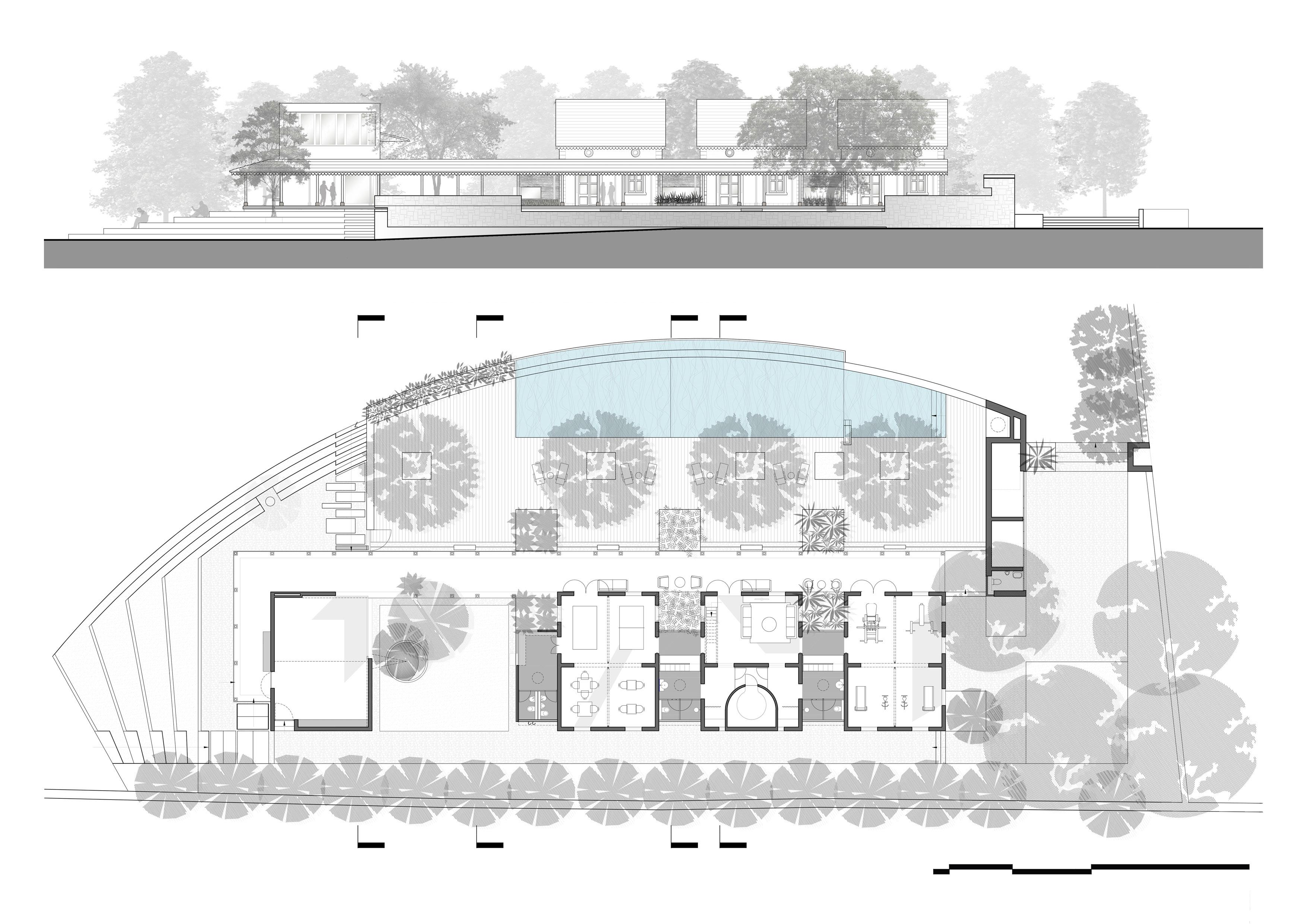
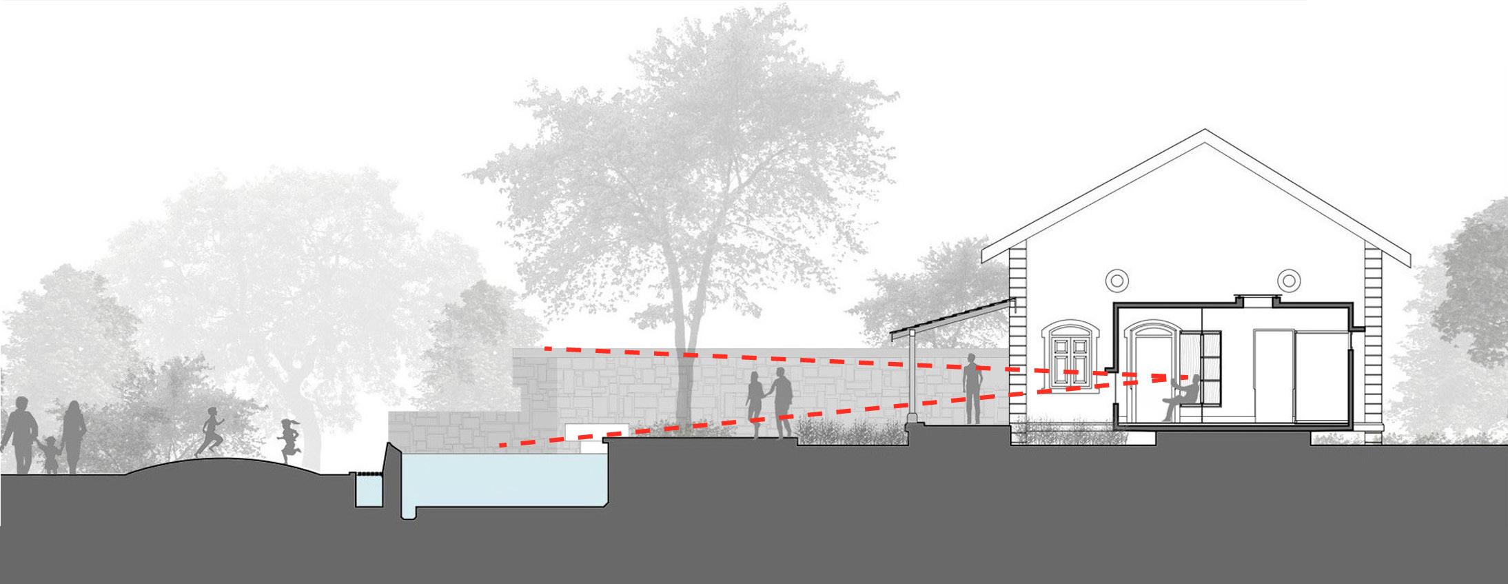
Shantivan is a settlement of second homes, which proved leisure and weekend relax ation opportunity. The clubhouse offers amenities such as swimming pool, game room, small ceremonial hall, gym, sauna and mini-library. The idea was to preserve the old structures and add some new elements to enhance the beauty of the old structure. But while doing that harmony must be maintained and old buildings should be given the respect and space that they deserve so that one could admire the old Architecture.
• Developed the design in conjunction with the company’s principal architect.
• Drafted Municipal, Construction and sale drawings.
• Conducted meeting and co-ordinated work with sauna and swimming pool con sultants.
Implemented pool and sauna details into community and construction drawings.
Conducted site supervision and performed on-site quality control.
• Documented on site changes and developed As-built drawings for further Munici pal Submission.

 CLUBHAUS Rendering-Software Twinmotion
2
a. Pump Room
b. Fitness Studio
c. Lobby d. Table sports
Multipurpose
Library
a. Existing structure
a. Existing structures b. Junction box c. Frontal separation
a. Existing structures
b. Junction box
c. Frontal Separation d. Additional unit
a. Existing structures b. Junction box c. Frontal Separation d. Remodeled unit e. Swimming pool f. Amphitheater
a. Existing structures b. Junction box c. Front Separation d. Multipurpose house e. Swimming pool f. Amphitheater g. Pump room h. Connecting corridor
1. Entrance to the Clubhouse
2. Verandah

Amphitheater
Bench
Multipurpose Hall
Rainwater Catchment Tank
Overflow Yard
Pool Deck
Swimming Pool
10. Children’s bath
11. Outdoor Shower
Utilities and Services
Back Entrance
Gymnasium
Connecting Corridor
Water Area
Steam Room
Living Room
19. Dressing Room
Game Room
Lobby
Toilet
Library
Common Garden
1. Entrance to the Clubhouse
2. Verandah
3. Amphitheater
Bench
Multipurpose Hall
Rainwater Catchment Tank
Overflow Yard
Pool Deck
Swimming Pool
10. Children’s bath
Outdoor Shower
Utilities and Services
13. Back Entrance
Gymnasium
Connecting Corridor
Water Area
Steam Room
Living Room
19. Dressing Room
Game Room
Lobby
Toilet
Library
Common Garden


 Location
 Location Location LocationVerandah
Multipurpose hall
Common Bathrooms
Amphitheatere Passage
Location
Location Location Location LocationVerandah
Multipurpose hall
Common Bathrooms
Amphitheatere Passage
Building typology
Building location
Architect’s office Area
Completed Shantivan House Lonavala | India S+PS Architects 304 sq. m.
Shantivan is a settlement of second homes, which proved leisure and weekend relax ation opportunity. The 5-bhk houses were top houses, which had their own open space. The bungalow was designed to meet the high demands of its future residents. In total there were 3 houses with similar design and different plot sizes.
• Developed a requirements plan with the Principle architect and the client.
• Developed design in conjunction with the firm’s principal architect.
• Executed and released construction, municipal and sales drawings.
Conducted client meetings. Coordinated with contractors during construction.
• Resolved problems on site.
• Quality controlled construction and finishes.
 5BHK Rendering Software Blender
GROUND FLOOR
FLOOR PLANS

0.12 0.23 1.16 0.12 0.12 2.37 0.28 0.35 0.66 0.44 3.02 0.44 0.52 0.34

0.34 0.27 0.58 0.35 0.35 1.05 0.35 2.37 0.28 0.35 0.66 0.44 3.02 0.44 0.52 0.34
0.35 0.12
0.34
230MM THK BRICK WALL WITH 115MM THK EXPOSED BLACK BASALT STONE CLADDING ON OUTSIDE AND TOP TO PLASTER INSIDE.
25MM THK GHUTAI FINISHED EXTERNAL ALL AROUND PLASTER
25MM THK ROUGH BLACK KADDAPA STONE WITH
OPENING

SLAB OVER DUCT WITH ONLY VENT COWLS OVER SLAB

12MM THK MULTI-WALL POLYCARBONATE SHEET AS PER APPROVED SAMPLES OVER 50x50 M.S. BOX SECTIONS AS COVER OVER VERANDAH
8MM THK TOUGHENED GLASS WITH 1.5 PVB LAMINATION + 8MM THICK TOUGHENED GLASS
115 X 115 BRICK CURB WITH 25MM THK EXTERNAL PLASTER
100MM X 115MM THK CONCRETE UP-STAND ALL AROUND
CHINA CLAY MOSAIC FINISH OVER BRICK COBA WATER PROOFING
300 x 150 R.C.C. PERGOLA WITH 25 MM THK EXTERNAL PLASTER 115 X 115MM THK BRICK CURB ALL AROUND
150MM THK & 750MM PROJECTION CANTILEVERED SLAB ALL AROUND.


Project status
Project name
Building typology
Building location
Architect’s office
Area
Completed Time piece
Kinetic Sculpture
Moscow | Russia
One World Studio Gmbh 38.5 sq.m. (24m Tall)
One World Studio Gmbh was commissioned to revive an old art action. The sculpture was designed with human history in mind and runs on several levels of shopping malls. New structural elements were installed, many mechanical elements were added and all together with a video content design and sound design a kinetic sculpture was installed that currently holds a Guinness Book record.
• Developed design ideas and drawings for construction purposes.
Developed preliminary design for the construction of the sculpture units
Developed suitable design alternatives for the structure with the structural engineer
• Exchanged information with the construction team
• Quality controlled during production and On-site assembly.
• Supervised and maintained construction reports.
• Conduct various on-site meetings with mall architects and maintenance team.
Maintained work logs and daily updates on the work being performed
Conducted quality control testing and performed reviews
Organized training for ground staff in the areas of maintenance and operations.

 HOROSHO Rendering Software Blender


0.55 1.20 0.20 0.45SQUARE TUBE
1.5 0.23 0.17 0.12 0.22 0.45 0.14 0.04 0.15 0.59 0.19 0.78 0.22 0.24 102°
A 0.20 0.22 0.06 0.18 0.46 0.03 0.15 0.18 0.05 0.18 0.03 0.09 0.08 0.06 0.080.010.000.01 0.02 0.03 0.03 0.01 0.05 0.09 0.07 0.16
TUBE 30 x 1.5
0.04 0.15 r= 1.50
5.82 2.70 0.18 0.21 0.15 0.20 0.23 0.28
6.35 0.32 0.13 0.55 1.00 1.20 2.07
0.55
6.73 0.29 1.20 2.42 Ø 5.74 0.91 r= 2.87 1.07 1.19 0.88 0.91 0.15 CHS 0.61 x8 2.14 0.59 0.04 0.19 1.051.120.25 0.41
0.05
1.00 0.27 0.40 +1.20 +1100mm +700mm +300mm
Project name
Building typology
Building location
Architect’s office Area
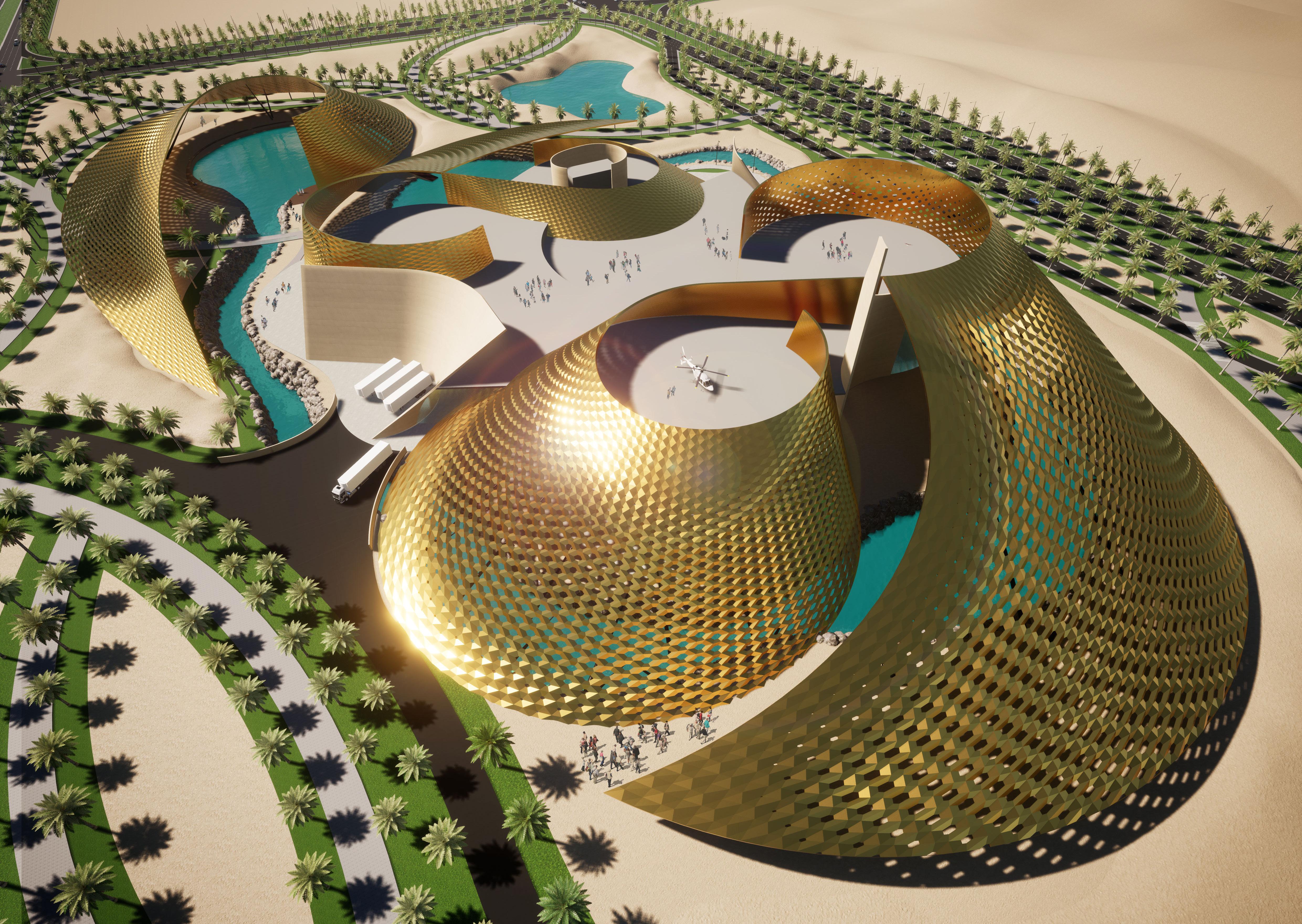
Concept Theme Park Mixed Kazakhstan
One World Studio Gmbh 255 Hectare
The client, who owns a Moto GP race track adjacent to the 255 hectare site, wanted to create a complete entertainment oasis with a full spectrum of entertainment and family leisure parks. Requirements included an amusement park, a car museum, an adventure shopping center, a wildlife and bird sanctuary, a water park, and 5 themed 5-star hotels spread across the site. This park was designed with sustainability and the SDG s in mind.
• Designed Layouts and Developed Road and Infrastructure outlines
• Developed a complete site plan.
Developed building blocks as well as a design for landscape and topography. Assigned roles as Project architect to design team considering their strengths.
• Coordinated and controlled illustrators and 3D developers for desired outcome.
• Conducted meetings with clients as project architect.
• Presented the final outcome in Kazakhstan for share holders.


Project name
Building typology
Building location
Architect’s office Area
One World studio Gmbh Na
The Adventure Sports Center is a concept building where people can try out and buy any adventure sports equipment. The idea of combining entertainment with retail has been brought to life in this building. The concept of the building is based on sand, jali architecture and computer algorithms that can optimize the gaps for good quality sun light and make the building habitable.
• Developed Facade design Concept
• Designed and developed building and infrastructure surrounding. Developed floor plans.
Development of a 3D model and rendering of videos and images for presentation purposes

Project name
Building typology
Building location
Architect’s office Area
Concept Mixed Mixed World
One World Studio Gmbh
Na
Besides designing and developing architectural buildings, I had a strong interest in me chanical working principles. Over the years, I explored different working principles with all kinds of projects. Some of them were innovative rides that could trigger adrenaline rushes, while others were for entertainment.
• Realized the ideas of Office In-charge
• Developed designs and 3dimensional armatures
Constructed 3d and animations
Identified specialization requirements
• Created project plans and schedules
• Communicated and consulted with vendors
• Coordinated and advised on quality control of structural details.
• Quality controlled fabricated units.
Quality controlled testing of finished products.


 GYRO RIDE Rendering Software Blender

MA ARCHITECT pratik.taishete@gmail.com +49 151 719 799 84 pratik.taishete www.linkedin.com/in/arpratik CONTACT
