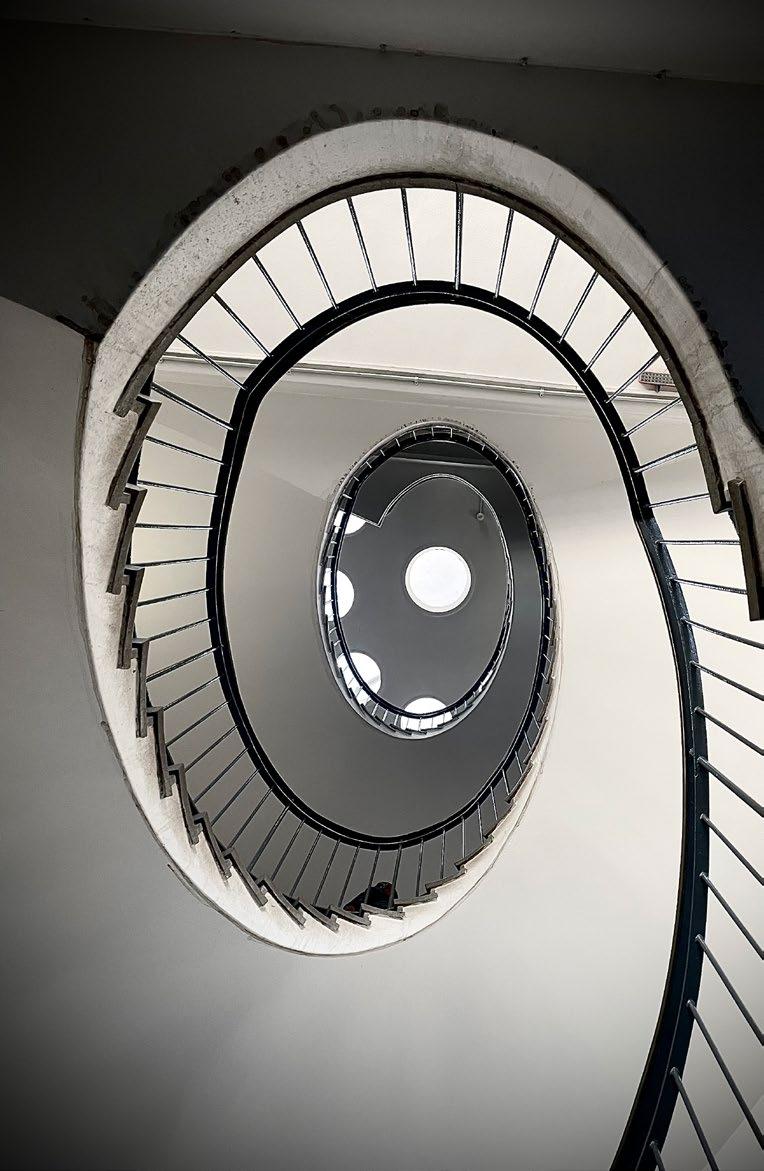
STRUCTURE
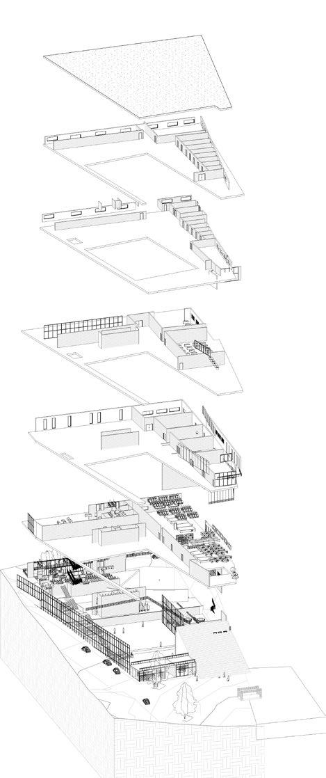
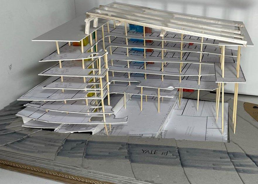
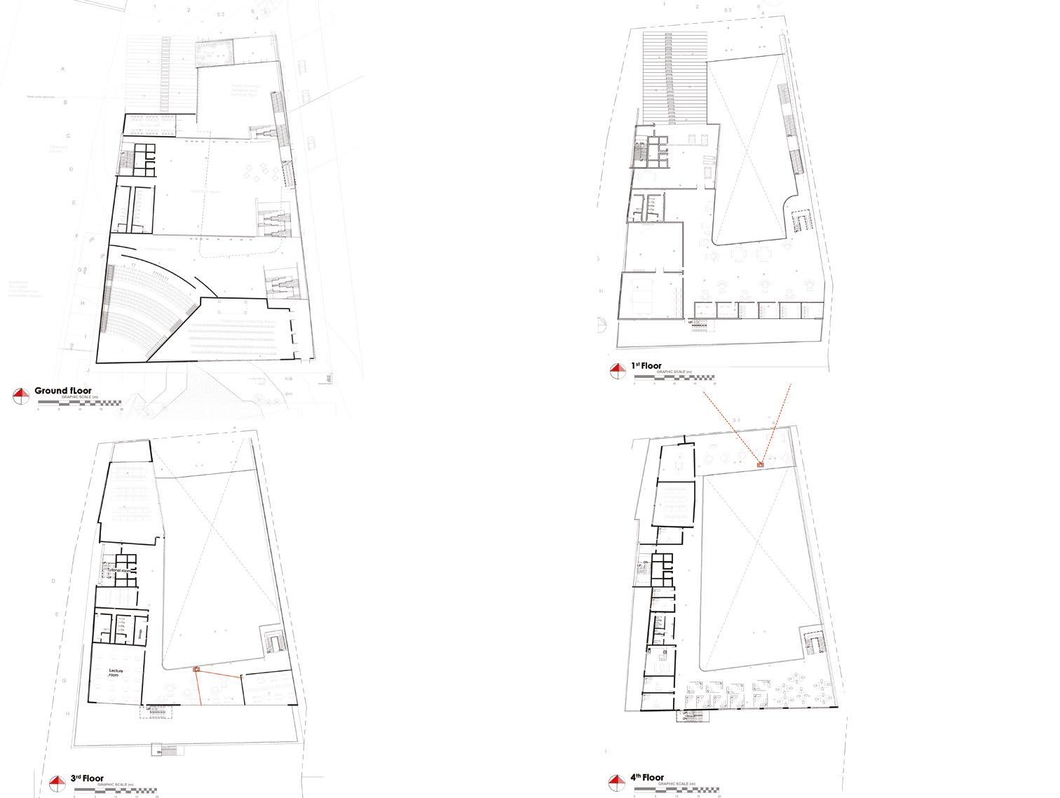

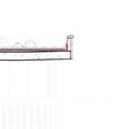
A10-10_Top of Parapet 35955


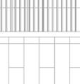
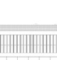
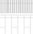

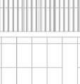

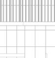

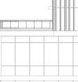

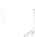

A10-09 Roof_TOC 35105

A10-08_6th Floor_TOC 32045
A10-07_5th Floor_TOC 28985
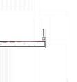
A10-06.1_Top of Upstand 26180
A10-06_4th Floor_TOC 25925
A10-05.1_Top of upstand 21335
A10-05_3rd Floor_TOC 21080
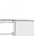
A10-04_2nd Floor_TOC 16065


A10-03.1_Top of upstand 11305
A10-03_1st Floor_TOC 11050

A10-02_Upper GF_TOC 6460




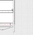
A10-01_Lower
A10-12_Basement -8 5076
DN 83 m m93 m04 m14 m24 34 m m44 m14 24 m 34 m 44 m 54 m m54 64 m m44 1 2 3 4 5 6 B C D E F G H J ERF- 321/53 ERF-320/53 36.43 m A B C D E F DE VELLIERS GRAAFF MOTORWAY YALE ROAD AMIC DECK PROPOSED NEW ROAD LEADING TO BASEMENT Exec Air TM Jet Air Rooftop Package Airconditioner – 108.0KW Semitransparent Building-Integrated Photovoltaic (BIPV) Glass Planet TM Solar reflecting glass @ 20° pitch FBO FBO FBO FBO FBO FBO FBO FBO FBO FBO FBO FBO FBO FBO FBO 250mm ⌀ storm FBO TO 100mm ⌀ SW down pipe to sump 250mm ⌀ storm FBO TO 100mm ⌀ SW down pipe to sump 250mm ⌀ storm FBO TO 100mm ⌀ SW down pipe to sump 50mm Brown Roof with non-woven root barrier drainage barrier and root barrier 510 mm Concrete Roof with a torch on bituminous membrane 500mm Perpet wall Fall 1:80 Fall 1:100 Fall 1:100 8400 8400 8400 8400 8400 8400 8400 8400 8400 8 00 84 0 40 8400 ERF- 370/53 External Fire escape steel monolithic stairway with 1000mm heigh balustraides 1000mm heigh Glass Planet TM balustrades made from laminated glass MH IE Scale Checked by Drawn by Date Project number P-Design Studio Physical Address: 1413 lakewood Terrace, Johannesburg 2091 TEL:0820504474 Email Adrdress:2107046@students.wits.ac.za Revision 1. This drawing not to be scaled, use figured dimensions only. All dimensions, heights, and angles to be checked and erified by the contractor before any work commences on site or in the contractor workshop and any discrepancies must be reported to the architect immediately 2. All building work to be carried out in accordance with the NBR, SANS, OHS, regulations and standards, and local authority by laws. 3. All structural components are to be verified and inspected by the structural engineer 4. All workmanship and materials are to be of the best available quality. 5. All architectural materials and products are to be as per the architect specification or equal and approved alternative. Should there be any discrepencies the architect should be notified 6. Any errors, discrepancies, omissions or queries arising from this documentation are to be reported to the architect mmediately for clarification 7. This drawing to be read in conjuntion with all othe drawings 8. All dimension are in millimeters unless stated otherwise 9. Repetitive mechanical and electrical hardware to be eliminated according to mechanical and electrical architects' guidelines, all dividers, floors, and soffits are o be made acceptable and arranged to get new completes according to the draftsman's timetable. All excess openings left by the expulsion of repetitive mechanical gear are to be deterred and fixed according to the designers determination and detail 10. All trash and tools shall be removed from premises each day and the area left clean whenever unattended 1. All plumbing work to be carried out in accordance with the NBR, SANS, OHS, regulations and standards, and local authority by laws. 2. The contractor responsible for verification of a field dimensions, locations and conditions prior to the urchase of any materials and commencement of work 3. All equipment and material provided shall fit withi the space provided. All equipment, fixtures, and serviceable devices shall be installed with access and clearance for maintenance. Coordinate with the general contractor and other trades to provide this access and clearance. Install all equipment and materials per manufacturer's instructions 4. Coordinate all locations and sizes of structural oor and wall penetrations with the general contractor and provide code required seals atall fire rated wall, ceiling, roof and floor penetrations 5. Install plumbing and piping high points as tight as possible to the building structure to allow proper pitch and maximize ceiling height 6. Provide air vents at piping high points and drains at low points in mains 7. Elevations listed for all plumbing system piping in the contract documents are to be verified prior to construction against existing conditions, utilities and new construction All sloped plumbing systems shall have right of way over all other building system components. General Notes General Plumbing Notes 1 200 Project 6 2107046 370 Yale Rd. Johannesburg 2001 Issue Date 6.2 Author Checker 1 : 200 C10-01_Site Plan 1 RevDescriptionDateDrawnChecked
GF 255
F G H I J
SITE BOUNDRY 20° Roof Pitch 3768 900mm high 40mm⌀ aluminum top grab railing with an aluminum frame to arch. spec fixed to 220mm thick Corobrick Black Brick FBX brickwork laid at running bond with grey by round spigot stainless steel base plate 580 x800mm Furmanglass single glazed glass panes 369 8400 8400 8400 8400 8400 Proposed new road leading to the new basement
R @ 28 179.1 mm
233 1519 1233 11399
1 100 C10-01_East Elevation 1 10 15 20 GRAPHIC SCALE (m)
sections (200 150 x10) 460mm spacing





General

be carried out in accordance with the NBR, SANS, OHS, regulations and standards, and local authority by laws.


3. All structural components are to be verified and inspected by the structural engineer 4. All workmanship and materials are to be of the best available quality. 5. All architectural materials and products are to be as per the architect specification or equal and approved alternative. Should there be any discrepencies the architect should be notified 6. Any errors, discrepancies, omissions or queries arising from this documentation are to be reported to the architect mmediately for clarification 7. This drawing to be read in conjuntion with all othe drawings 8. All dimension are in millimeters unless stated otherwise









General Plumbing Notes


1. All plumbing work to be carried out in accordance with the NBR, SANS, OHS, regulations and standards, and local authority by laws.


2. The contractor is responsible for verification of all field dimensions, locations and conditions prior to the purchase of any materials and commencement of work 3. All equipment and material provided shall fit within the space provided. All equipment, fixtures, and serviceable devices shall be installed with access and clearance for maintenance. Coordinate with the general contractor and other trades to provide this access and clearance. Install all equipment and materials per manufacturer's instructions 4. Coordinate all locations and sizes of structural floor and wall penetrations with the general contractor and provide code required seals atall fire rated wall, ceiling, roof and floor penetrations 5. Install plumbing and piping high points as tight as possible to the building structure to allow proper pitch and maximize ceiling height 6. Provide air vents at piping high points and drains at low points in mains
A10-05_3rd Floor_TOC 21080



17
5. 600 x 600 5mm Ceremic hardbody Ecostone Beigh Ecotec stone look with 3mm spacing 4. 4mm thick polyster Derbigum waterproofing membrane with 75mm side laps and 100mm end laps sealed to primed surface to fall by torchfusion 200 200mm 10mm thick hallow core steal section bolted to concrete column 4860 Brick (finishing) 280mm thick Corobrick BlackBrick FBX brickwork laid at with 30mm air gap 30mm XPS insulation Summit running bond with grey mortar with single skin of brick work covering slab supported by a shelf angle min. 30mm cement screed with 75mm fillets on ends 114 x 38mm aluminum mullion 3000 2400mm Furmanglass doubelglazed glass panes fixed tointernal frame witg spider glass holders 4 x 27mm ⌀ stainless steel Fga Trading pty ltd spider glass holder bolted to 200 200mm steel section Weep hole 100 65 x10mm steel unequal angles Stewards and Lloyds anchor bolted to concrete slab with mortar trap and sealant and backer rod 1040 775 424 175 x 154mm aluminum storefront sill with labyrinth and a concealed drainage channel 114 x 31mm aluminum storefront jamb weak concrete infill Railing 900mm high 40mm⌀ aluminum top grab railing with an aluminum frame to arch. spec fixed to 220mm thick Corobrick Black Brick FBX brickwork laid at running bond with grey by round spigot stainless steel base plate A10-09 Roof_TOC 35105 A10-10_Top of Parapet 35955 Roof Detail Top to bottom 140mm growing substrate kraal mis, top soil & riversand mixture 2mm thick HDPE woven geotextile root barrier 20mm HDPE core geotextile cuspated sheet 375μm DPM 50mm cement screed with 75mm fillets on ends 4mm thick polyster Derbigum waterproofing membrane with 75mm side laps and 100mm end laps sealed to primed surface to falla b torchfusion 3. 60 60mm 4mm thick galvanised steel tube primed and painted white welded to adjacent sections 2. 88.9mm ⌀ 4mm thick galvanised steel tube primed and painted white welded to adjacent sections 1. 100mm ⌀ 4mm thick galvanised steel tube primed and painted white welded to adjacent sections 4. 219mm ⌀ 4mm thick galvanised steel tube primed and painted white welded to adjacent sections 10mm weak concrete A 6. 88.9mm ⌀ 4mm thick galvanised steel tube primed and painted white welded to adjacent sections 18mm thck double glazed glass sitting on an aliminum frame 100 x 65 x10mm steel unequal angles Stewards and Lloyds anchor bolted to concrete slab with mortar trap and sealant and backer rod 100 x 65 x10mm steel unequal angles Stewards and Lloyds anchor bolted to concrete slab with mortar trap nd sealant and backer rod 347 406 406 100mm cast insitu concrete coping with a slope 92° towards roof 174 1 5 0 ø 0 1221 1180 1790 880 x150 19mm steel wall plate Stewards and Lloyds anchor bolted to concrete bolt to concrete wall wit m20 bolt Truss Note 504 500mm thick concrete wall to eng, spec 516 x 406mm metal copping A10-01_Lower GF 255 250mm poisned compacted fill 450 x450 50mm concrete paver Pavement material group charcoal colour layed in a stack bond pattern 4mm soecial polyester Durbigum waterproofing membrane applied via tourch on method 300 100 mild steel stormwater grating Mantis fixed to bearer bar and transverse bar pitch of 40mm bonded along span only bitumen dipped finish min. 30mm screed laid to a 1:80 fall with max build up of 100mm 325 x 325mm precast trench drain with 250mm ⌀ storm FBO TO 100mm ⌀ SW down pipe to sump 27mm ⌀ stainless steel Fga Trading pty ltd spider glass holder bolted to 200 x 200mm steel section 3000 x 2400mm Furmanglass doubelglazed glass panes fixed tointernal frame witg spider glass holders 175 154mm aluminum storefront sill with labyrinth and concealed drainage channel 200 200mm 10mm thick steal section hallow core Stewards and Lloyds bolted to concrete column 114 38mm aluminum mullion 300 5 1 0 Scale Checked by Drawn by Date Project number P-Design Studio Physical Address: 1413 lakewood Terrace, Johannesburg 2091 TEL:0820504474 Email Adrdress:2107046@students.wits.ac.za Revision 1. This drawing is not to be scaled, use figured dimensions only. All dimensions, heights, and angles to be checked and erified by the contractor before any work commences on site or in the contractor workshop and any discrepancies must be reported to the architect immediately 2. All building work to be carried out in accordance with the NBR, SANS, OHS, regulations and standards, and local authority by laws. 3. All structural components are to be verified and inspected by the structural engineer 4. All workmanship and materials are to be of the best available quality. 5. All architectural materials and products are to be as per the architect specification or equal and approved alternative. Should there be any discrepencies the architect should be notified 6. Any errors, discrepancies, omissions or queries arising from this documentation are to be reported to the architect mmediately for clarification 7. This drawing to be read conjuntion with all othe drawings 8. All
9. Repetitive
eliminated
guidelines,
acceptable
All
10. All
unattended 1. All plumbing work to be carried out in accordance with the NBR, SANS, OHS, regulations and standards, and local authority by laws. 2. The contractor responsible for verification of a field dimensions, locations and conditions prior to the purchase of any materials and commencement of work 3. All equipment and material provided shall fit withi the space provided. All equipment, fixtures, and serviceable devices shall be installed with access and clearance for maintenance. Coordinate with the general contractor and other trades to provide this access and clearance. Install all equipment and materials per manufacturer's instructions 4. Coordinate all locations and sizes of structural oor and wall penetrations with the general contractor and provide code required seals atall fire rated wall, ceiling, roof and floor penetrations 5. Install plumbing and piping high points as tight as possible to the building structure to allow proper pitch and maximize ceiling height 6. Provide air vents at piping high points and drains at low points in mains 7. Elevations listed for all plumbing system piping in the contract documents are to be verified prior to construction against existing conditions, utilities and new construction All sloped plumbing systems shall have right of way over all ther building system components. General Notes General Plumbing Notes 1 25 Project 6 2107046 370 Yale Rd. Johannesburg 2001 Issue Date 6.2 Author Checker 1 25 C10-01_PS_3 Copy 1 1 RevDescriptionDateDrawnChecked B C D E NGL SITE BOUNDRY 850 220mm thick Corobrick Black Brick FBX brickwork laid at running bond with grey mortar with a concret coping Pitch 501 x 501mm Parallel Slat, RS PRO Silver Aluminium Louvre, Fixed to an aluminum frame PG Glass Double glazed storefront glass panels fixed to an aluminum frame Semitransparent Building-Integrated Photovoltaic (BIPV) Glass Planet TM Solar reflecting glass @ 20° pitch 900mm high 40mm⌀ aluminum top grab railing with an aluminum frame to arch. spec fixed to 220mm thick Corobrick Black Brick FBX brickwork laid at running bond with grey by round spigot stainless steel base plate 580 x 799mm Furmanglass single glazed glass panes 8400 8400 8400 8400 750 1239 1310 806 1099 1572 1948 1848 347 6493 2299 4905 1799 2642 409 362 201 185 155 341 1507 CW_1 4750 293 294 136 4500 aluminum vertivcal scrrensfixed to rectangulat hallow metal sections (200 150 x10) 4505 CW_1 height noted on tag with a width of 1508mm Furmanglass double glassed panels fixed to a n aluminum frame 4610 x 1500 x 6mm recycled metal sheets fixed to rectangular hallow section (200 x 150 x 10mm) left exposed to elemets to allow rustic finoish 4610 1500 x 6mm recycled metal sheets wih laser cut perforations fixed to rectangular hallow section (200 x 150 x 10mm) left exposed to elemets to allow rustic finoish 1360 4500 aluminum vertical screens fixed to rectangular hallow metal
Scale Checked by Drawn by Date Project number P-Design Studio Physical Address: 1413 lakewood Terrace, Johannesburg 2091 TEL
Email Adrdress:2107046@students.wits.ac.za Revision
A10-06_4th Floor_TOC 25925
dimension are in millimeters unless stated otherwise
mechanical and electrical hardware to be
according to mechanical and electrical rchitects'
all dividers, floors, and soffits are o be made
and arranged to get new completes according to the draftsman's timetable.
excess openings left by the expulsion of repetitive mechanical gear are to be deterred and fixed according to the designers determination and detail
trash and tools shall be removed from premises each day and the area left clean whenever
:0820504474
Notes 1. This drawing is not to be scaled, use figured dimensions only. All dimensions, heights, and angles to be checked and erified by the contractor before any work commences on site or in the contractor workshop and any discrepancies must be reported to the architect immediately 2. All building work to
1 100 No 6.2 Project 6 2107046 Issue Date Author Checker 370 Yale
Johannesburg 2001 RevDescriptionDateDrawnChecked
Rd.
A10-09 Roof_TOC 35105

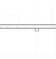
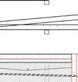

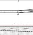
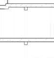
A10-08_6th Floor_TOC 32045
A10-07_5th Floor_TOC 28985
General Notes 1. This drawing not to be scaled, use figured dimensions only. All dimensions, heights, and angles to be checked and erified by the contractor before any work commences on site or in the contractor workshop and any discrepancies must be reported to the architect immediately 2. All building work to be carried out in accordance with the NBR, SANS, OHS, regulations and standards, and local authority by laws. 3. All structural components are to be verified and inspected by the structural engineer 4. All workmanship and materials are to be of the best available quality. 5. All architectural materials and products are to be as per the architect specification or equal and approved alternative. Should there be any discrepencies the architect should be notified 6. Any errors, discrepancies, omissions or queries arising from this documentation are to be reported to the architect mmediately for clarification 7. This drawing to be read in conjuntion with all othe drawings 8. All dimension are in millimeters unless stated otherwise






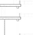
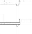
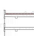
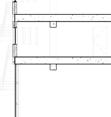

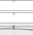
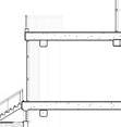
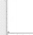
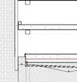
A10-05_3rd Floor_TOC 21080
A10-06_4th Floor_TOC 25925 A10-04_2nd Floor_TOC 16065
A10-03_1st Floor_TOC 11050
A10-02_Upper GF_TOC 6460
















A10-01_Lower GF 255
A10-10_Basement -1 -3158



A10-11_Basement -2 -6158

A10-12_Basement -3 -9158
General Plumbing Notes 1. All plumbing work to be carried out in accordance with the NBR, SANS, OHS, regulations and standards, and local authority by laws. 2. The contractor is responsible for verification of all field dimensions, locations and conditions prior to the purchase of any materials and commencement of work 3. All equipment and material provided shall fit within the space provided. All equipment, fixtures, and serviceable devices shall be installed with access and clearance for maintenance. Coordinate with the general contractor and other trades to provide this access and clearance. Install all equipment and materials per manufacturer's instructions 4. Coordinate all locations and sizes of structural floor and wall penetrations with the general contractor and provide code required seals atall fire rated wall, ceiling, roof and floor penetrations 5. Install plumbing and piping high points as tight as possible to the building structure to allow proper pitch and maximize ceiling height 6. Provide air vents at piping high points and drains at low points in mains
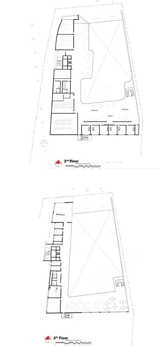
B C D E F G H J Floor Finish:Porcelain Tiles Area:403 m² Multiperpose Gathering Floor Finish:Porcelain Tiles Area:78 m² Multiporpose lobby Floor Finish:Porcelain Ties Area:889 m² Exhibition Space 8400 8400 8400 8400 8400 8400 8400 8400 8400 Floor Finish:Porcelain Tiles Area:22 m² Private Study Floor Finish:Porcelain Tiles Area:26 m² Consultation Room Floor Finish:Porcelain tiles Area:58 m² Consultation room Passage Floor Finish:Porcelain Tiles Area:349 m² Wellness CentreWaiting Area Floor Finish:Porcelain Tiles Area:99 m² Library Floor Finish:Porcelain Tiles Area:344 m² Open Plan Offices Floor Finish:Porcelain Tiles Area:345 m² Open Plan Offices Floor Finish:Porcelain Tiles Area:344 m² Open Plan Offices Roof Detail Top to bottom 140mm growing substrate kraal mis, top soil & riversand mixture 2mm thick HDPE woven geotextile root barrier 20mm HDPE core geotextile cuspated sheet 375μm DPM 50mm cement screed with 75mm fillets on ends 4mm thick polyster Derbigum waterproofing membrane with 75mm side laps and 100mm end laps sealed to primed surface to falla b torchfusion 1 5 0 Window 2400 x 1200mm aluminum framed window Kenzo PTT218 Top hung with 8mm thick glass 324 113mm cast-insitu concrete bonded below to 10mm mortar Brick (finishing) 280mm thick Corobrick BlackBrick FBX brickwork laid at a with 30mm air gap 30mm XPS insulation Summit running bond with grey mortar with single skin of brick work covering slab supported by a shelf angle 106 73mm and 150 x73mm pre-stressed concrete lintles 100 x 65 x10mm steel unequal angles Stewards and Lloyds anchor bolted to concrete slab with a mortar trap and sealant and backer rod 100 65 x 10mm steel unequal angle Stewards and LLoyds anchor bolted to concrete slabwith mortar trap and sealant backer rod Storfront (Inspo ThermEco Sash Windows) 42mm deep mullions 1500 x1500 top hung middle section 1400 x1400mm 10mm thick low-e glazing panels Railing 900mm high 40mm⌀ aluminum top grab railing with an aluminum frame to arch. spec fixed to 220mm thick Corobrick Black Brick FBX brickwork laid at running bond with grey by round spigot stainless steel base plate Storfront (Inspo ThermEco Sash Windows) 42mm deep mullions 1500 x1500 top hung middle section 1400 x1400mm 10mm thick low-e glazing panels Storfront (Inspo ThermEco Sash Windows) 42mm deep mullions 1500 x1500 top hung middle section 1400 x1400mm 10mm thick low-e glazing panels 700 2400mm aluminum ventilation grill RS PRO 200 300mm pile cap with a x 100mm to beadrock/stable soil to eng spec 100mm ⌀ geopipe perfforated PVC harringbone pattern @ 1:100 fall 40mm gravel Basement Floor Top to bottom 510mm thick floor slab 2.5mm thick polyethlene sheet Flowcem DPM Flowcrete SA (Pty) Ltd with a matt finish 375mm sand blinding layor 40mm gravel Graded poisoned compacted fill in layers of a max of 150mm 260 195 540mm sump pump The hurrican Wsd18-12.1.3cd 220v 1.3kw 2000 x1000 x1500 mild steel bitumen dipped Mentis sump pump mount 4mm thick polyster Derbigum waterproofing membrane lining the concrete sump 450 x450 x 50mm concrete paver Pavement material group charcoal colour layed in a stack bond pattern 250mm thick sand blinding layer 300 x 1000mm Mentis Trench Cover with bar size of 50 4.5mm Flooring (top to bottom) -450 x450 x 50mm concrete paver -4mm thick polyster Derbigum waterproofing membrane Min 30mm screed to fall -FBO ACO Spin flat roof drain DN 70 made of cast iron for gravity drainage 290mm ⌀ drain cast iron top cercullar top section -325 x 325 precast concrete ReMaCon channel fixed to concrete slab to a 50mm ⌀ PVC pipe 3000 x 2400mm Furmanglass doubelglazed glass panes fixed to internal frame witg spider glass holders 4 27mm ⌀ stainless steel Fga Trading pty ltd spider glass holder bolted to 200 200mm steel section 200 200mm 10mm thick steal section hallow core Stewards and Lloyds bolted to concrete column Balcony -600 600 5mm Ceremic hardbody Ecostone Beigh Ecotec stone look with 3mm spacing -10mm champion tile adhesive -4mm thick polyster Derbigum waterproofing membrane with 75mm side laps and 100mm end laps sealed to primed surface to falla by torchfusion -50mm cement screed with 75mm fillets on ends Roof Detail Top to bottom 140mm growing substrate kraal mis, top soil & riversand mixture 2mm thick HDPE woven geotextile root barrier 20mm HDPE core geotextile cuspated sheet 375 m DPM 50mm cement screed with 75mm fillets on ends 4mm thick polyster Derbigum waterproofing membrane with 75mm side laps
50% expanded clay, shale, or perlite; 30% decomposed granite; and 20% rice husks or another fine, slowly-degradable organic matter. Scale Checked by Drawn
Date Project number
Revision
and 100mm end laps sealed to primed surface to falla by torchfusion
by
P-Design Studio Physical Address: 1413 lakewood Terrace, Johannesburg 2091 TEL:0820504474 Email Adrdress:2107046@students.wits.ac.za
1 100 No 6.2 Project 6 2107046 Issue Date Author Checker 370 Yale Rd. Johannesburg 2001 1 100 C10-01_Section1 1 RevDescriptionDateDrawnChecked
355 x168 x460mm stainless steel Franke waste with a satin finish fixed 500mm above FFL to wall with M6 50 A2 S/S coach screw with a 9mm sway wall plug
280 x 207 x247mm stainless steel sensor Franke sensor operated handryer with satin finish mounted to the wall with a spidle system @ a height of 1120mm
5130 876 quartz vanity Ceasarstone Vanilla Noir Polished fixed to 35 x 35mm hallow tube metal frame [See Vanity Detail for more]
General Notes
This drawing is not to be scaled, use figured dimensions only. All dimensions, heights, and angles to be checked and verified by the contractor before any work commences on site or in the contractor workshop and any discrepancies must be reported to the architect immediately 2. All building work to be carried out in accordance with the NBR, SANS, OHS, regulations and standards, and local authority by laws. 3. All structural components are to be verified and spected by the structural engineer 4. All workmanship and materials are to be of the best available quality. 5. All architectural materials and products are to be as per the architect specification or equal and approved alternative. Should there be any discrepencies the architect should be notified 6. Any errors, discrepancies, omissions or queries arising from this documentation are to be reported to the architect mmediately for clarification 7. This drawing to be read in conjuntion with all othe drawings 8. All dimension are in millimeters unless stated otherwise
Plumbing Notes
General
330 x450 x350 mm ceremic Alson Urinal mounted on wall with a concelaed bracket under side of UR. 300mm above FFL repeated for all instalations at 1004mm centre to centre
370x370x120 ceramic round Counter basin Studio white with glossy finish mounted to the wall Under side of vanity 680mm above FFL (male & female disable acces toilet) 283
280 x 207 x247mm stainless steel sensor Franke sensor operated handryer with satin finish mounted to the wall with a spidle system @ a height of 1120mm above FFL
355 x168 x460mm stainless steel Franke waste with a satin finish fixed 500mm above FFL to wall with M6 x 50 A2 S/S coach screw with a 9mm sway wall plug
320x320x320mm 32mm⌀ stainless steel Intal grabrail fixed to wall with M6 50 A2 S/S coach screw with a 9mm sway wall plug @ 680mm above FFL
95 x 90 x 90 700mm 32mm ⌀ stainless steel Intal grabrail fixed to wall with M6 50 A2 S/S coach screw with a 9mm sway wall plug @ 680mm above FFL
Waste Pipe 50mm ⌀ Marley PVC pipes with 50⌀ plain junction and 90° 50⌀ S/V bend with a 50⌀mm vent pipe along run Soil Pipes 110 ⌀ Marley PVC pipes with 110 x 50x 190 S/V junction 90° 110⌀ S/V bend with a 150⌀ vent pipe along run
455 559 141 400
61 0 28 6 3 280 x 207 x247mm stainless steel sensor Franke sensor operated handryer with satin finish mounted to the wall with a spidle system @ a height of 940mm above FFL
CWS 32mm ⌀ Brassman copper pipe connected with a 35mm ⌀ Brassman connecting elbow & 35mm ⌀ Brassman compresion equal Tee
200 x 140 x 132mm stainless steel Franke soap dispenser, chrome finish fixed 1120mm above FFL to wall with M6 x 50 A2 S/S coach screw with 9mm sway wall plug 355 x168 x460mm stainless steel Franke waste with a satin finish fixed 500mm above FFL to wall with M6 50 A2 S/S coach screw with 9mm sway wall plug
320x320x320mm 32mm⌀ stainless steel Intal grabrail fixed to wall with M6 50 A2 S/S coach screw with a 9mm sway wall plug @ 680mm above FFL
156 x 203 x 141mm Stainless steel Franke toilet roll holder double roll holder with aI InoxPlus surface refinement fixed with spidle system @ 680mm above FFL (used in all cubicals) 95 90 x 90 x 700mm 32mm ⌀ stainless steel Intal grabrail fixed to wall with M6 50 A2 S/S coach screw with 9mm sway wall plug @ 680mm above FFL
at running bond with 10mm grey mortar
1. All plumbing work to be carried out in accordance with the NBR, SANS, OHS, regulations and standards, and local authority by laws. 2. The contractor is responsible for verification of all field dimensions, locations and conditions prior to the purchase of any materials and commencement of work 3. All equipment and material provided shall fit within the space provided. All equipment, fixtures, and serviceable devices shall be installed with access and clearance for maintenance. Coordinate with the general contractor and other trades to provide this access and clearance. Install all equipment and materials per manufacturer's instructions 4. Coordinate all locations and sizes of structural floor and wall penetrations with the general contractor and provide code required seals atall fire rated wall, ceiling, roof and floor penetrations 5. Install plumbing and piping high points as tight as possible to the building structure to allow proper pitch and maximize ceiling height 6. Provide air vents at piping high points and drains at low points in mains
1 E F Setting out Point Setting out Point TILES 600 x 600 x 5mm Ceremic hardbody Ecostone Beigh Ecotec stone look with 3mm spacing 1 2 D E F G 947947947 10041004100410041004 2183 995 915 314 7 0 5 1 3 0 1508 1400 ø 12 0 8398 8 3 7 8 3 7 8 3 7 8 3 7 8 3 7 1 6 8 6 1 6 8 6 915 2800 762 3524 915 9 2 940940940940 940 940 1878 1918 978 940 940 940 925 925 925 925 925 925 925 925 925 0764 9200 6 2 2 9 1 7 2 3 1 8600 9400 ° 9400 ° 8600 2 4 28 5 1 3 0 7 1729 915 224 920 730 2 5 9 6 4 7 8 895 228 118 229 296 295 177 762 91 915 x 2134mm Marine Ply with 850 850mm Trox AGS-T door grill with a Handles Inc. door handles screwed in place @ 700mm above FFL 355 x168 x460mm stainless steel Franke waste with satin finish fixed 500mm above FFL to wall with M6 x 50 A2 S/S coach screw with 9mm sway wall plug 280 x 207 x247mm stainless steel sensor Franke sensor operated handryer with satin finish mounted to the wall with a spidle system @ a height of 1120mm above FFL 9 4 5 2 8 8 5 8 6 1 9 8 6 5130 876 quartz vanity Ceasarstone Vanilla Noir Polished fixed to a 38 38mm hallow tube metal frame [See Vanity Detail for more] 7 8 6 7 8 6 7 8 6 7 8 6 7 8 6 0 1 5 3 1 1 6 3 1 9 5 8 4 206.4 61.9mm stainless steel Kohler push button tap fixed to vanity with mounting plate @ 771mm above FFL with 786mm center to center spacing 220mm thick Corobrick Black Brick FBX brickwork laid
above FFL 206.4 x 61.9mm stainless steel Kohler push button tap fixed to vanity with a mounting plate @ 771mm above FFL with 786mm center to center spacing 200 140 132mm stainless steel Franke oap dispenser, chrome finish fixed 1120mm above FFL to wall with M6 50 A2 S/S coach screw with a 9mm sway wall plug 156 x 203 x 141mm Stainless steel Franke toilet roll holder double roll holder with aI InoxPlus surface refinement fixed with a spidle system @ 680mm above FFL (used in all cubicals) 915 2134mm Marine Ply with 850 850mm Trox AGS-T door grill with a Handles Inc. door handles screwed in place @ 700mm above FFL 940 x1508 x 2000 with 16mm Particleboard faced with fomica T1 Toilet Partitions fixed on 22 x 22mm lipped aluminum frame with fixed to the floor and wall to Manfacteres Spec. 173 X 390mm Propelair plastic cistern mounted to the wall (Connected to battery pack see elctrical layout) 640 396 mm Ceremic Propelair WC Fixed to the floor 1 E F HD 1422 30568111 703 270 31385 1795 85 2400 1864 2400 305 1790 305 1575 304 1613 305 1613 297 1581 330 305 2700 305 1454 654 500 889 766 500 841 966 2400 1880 2400 85 1508 305 28 85 769 2 5 9 2 8 8 9 4 5 Scale Checked by Drawn by Date Project number P-Design Studio Physical Address: 1413 lakewood Terrace, Johannesburg 2091 TEL:0820504474 Email Adrdress:2107046@students.wits.ac.za Revision
1.
1 : 50 No 6.2 Project 6 2107046 Issue Date Author Checker 370 Yale Rd. Johannesburg 2001 RevDescriptionDateDrawnChecked 1 50 C11_01_Detail Tiles 1 1 50 C11_01_Plumbing & Water 2 1 50 C11_01_Ceiling 3 HD 280 x 207 x247mm stainless steel sensor Franke sensor operated handryer with satin finish mounted to the wall with aspidle system @ height of 1120mm above FFL connected to a switch 2000mm above FFL 2400 x 55 85 Metal and Polycarbonate Lynx Bar ligh hang from ceiling with cords 3000mm above FFLwith 72 watte LED 4000k cool white light 560lm with 120° beam angle and motion sensor 35 86 mm Plastic Veti light swich fixed to wall 1200mm above FFL 294 x149 24v DC Propelair Battery box charged by 230v smart charger 152mm ⌀ aluminum Premitorfue flexible duct connects to a 296 x 296 aluminum MMotors extractor fan 150 x 150mm cast aluminum SG wall light with a 22w SMD LED 400K 500lm
x 547mm
Adrdress:2107046@students.wits.ac.za
General Notes
1. This drawing is not to be scaled, use figured dimensions only. All dimensions, heights, and angles to be checked and v erified by the contractor before any work commences on site or in the contractor s workshop and any discrepancies must be reported to the architect immediately



2. All building work to be carried out in accordance with the NBR, SANS, OHS, regulations and standards, and local authority by laws.
3. All structural components are to be verified and inspected by the structural engineer
4. All workmanship and materials are to be of the best available quality.
5. All architectural materials and products are to be as per the architect specification or equal and approved alternative. Should there be any discrepencies the architect should be notified
6. Any errors, discrepancies, omissions or queries arising from this documentation are to be reported to the architect mmediately for clarification
7. This drawing to be read in conjuntion with all othe drawings
8. All dimension are in millimeters unless stated otherwise











9. Repetitive mechanical and electrical hardware to be eliminated according to mechanical and electrical architects' guidelines, all dividers, floors, and soffits are o be made acceptable and arranged to get new completes according to the draftsman's timetable.
All excess openings left by the expulsion of repetitive mechanical gear are to be deterred and fixed according to the designers determination and detail
General Plumbing Notes
1. All plumbing work to be carried out in accordance with the NBR, SANS, OHS, regulations and standards, and local authority by laws.
2. The contractor is responsible for verification of all field dimensions, locations and conditions prior to the purchase of any materials and commencement of work 3. All equipment and material provided shall fit within the space provided. All equipment, fixtures, and serviceable devices shall be installed with access and clearance for maintenance. Coordinate with the general contractor and other trades to provide this access and clearance. Install all equipment and materials per manufacturer's instructions 4. Coordinate all locations and sizes of structural oor and wall penetrations with the general contractor and provide code required seals atall fire rated wall, ceiling, roof and floor penetrations
5. Install plumbing and piping high points as tight as possible to the building structure to allow proper pitch and maximize ceiling height
6. Provide air vents at piping high points and drains at low points in mains
5 1 7 0 7 8 6 7 8 6 7 8 6 7 8 6 7 8 6 1 5 3 1 1 6 3 1 60 413 73 329 876 2 0 5 1 3 0 2 0 2 8 9 5 1 3 8 1 0 0 0 3 8 1 0 0 0 3 8 1 0 0 0 3 8 9 4 2 3 8 206.4 x 61.9mm stainless steel Kohler push button tap fixed to vanity with a mounting plate @ 771mm above FFL with 786mm center to center spacing 200 x 140 x 132mm stainless steel Franke soap dispenser, chrome finish fixed 1120mm above FFL to wall with M6 x 50 A2 S/S coach screw with a 9mm sway wall plug 40mm ⌀ PVC Plumline shank loacted under each tap 38 x38mm Mild steel hallow tube frame 2 5 8 1 4 8 3 1 9 3 7 8 1 4 8 2 1 9 3 3 7 1 4 8 2 4 0 800 800 800 1200 748 763 763 743 1531 786 786 786 CWS 32mm ⌀ Brassman copper pipe connected with a 35mm ⌀ Brassman connecting elbow & 35mm ⌀ Brassman compresion equal Tee along run 32 x 32mm 40 x 40mm brass Plumline universal bottle trap chrome finish 40mm ⌀ PVC Plumline shank Waste Pipe 50mm ⌀ Marley PVC pipes with 50⌀ plain junction and 90° 50⌀ S/V bend
200
2100 x
mirror Birch
step 1 GF 1275 437 195 20 38 60 278 632 160 00° 449 511 547 330 110 35 0 910 880 91 19
(x2) 7. 0715 x 330mm note Section 1-5 comprised of two pieces bonded Section: 1,4.5 (2585 x 2585mm) Section: 2,3 (2565 x 2565mm) 206.4 x 61.9mm stainless steel Kohler push button tap fixed to vanity with a mounting plate @ 771mm above FFL with 786mm center to center spacing CWS 32mm ⌀ Brassman copper pipe connected with a 35mm ⌀ Brassman connecting elbow & 35mm ⌀ Brassman compresion equal Tee along run Waste Pipe 50mm ⌀ Marley PVC pipes with 50⌀ plain junction and 90° 50⌀ S/V bend with a 50⌀mm vent pipe along run 250x150mm Metal Heavy Duty Stayed Bracket with Zinc plated & clear passivated steel hex Bolt, M8 x 20mm 32 x 32mm 40 x 40mm brass Plumline universal bottle trap chrome finish 38 x 38mm mild steel tube with 2mm wall 220mm thick Corobrick Black Brick FBX brickwork laid at running bond with 10mm grey mortar 600 x 600 x 5mm Ceremic hardbody Ecostone Beigh Ecotec stone look with 3mm spacing 200 x 140 x 132mm stainless steel Franke soap dispenser, chrome finish fixed 1120mm above FFL to wall with M6 x 50 A2 S/S coach screw with a 9mm sway wall plug 74 100 x 74 x 20 x 2mm mild steel lip channel 1 2 5 4 3 6 7 40mm ⌀ PVC Plumline shank Scale Checked
Drawn
Date Project number
Physical
Email
Revision
with a 50⌀mm vent pipe along run
x 140 x 132mm stainless steel Franke soap dispenser, chrome finish fixed 1120mm above FFL to wall with M6 x 50 A2 S/S coach screw with a 9mm sway wall plug 200 x 140 x 132mm stainless steel Franke soap dispenser, chrome finish fixed 1120mm above FFL to wall with M6 x 50 A2 S/S coach screw with a 9mm sway wall plug
800mm
Popsicle fixed with 30mm metal Eureka screws 2H45 with chrome caps 30mm metal Eureka screws 2H45 with chrome caps 30 740 30 43 1114 43
5130 x 876 quartz vanity Ceasarstone Vanilla Noir in 8 sections pieced togther with epxoy glue 1. 5170 x 300mm 2. 5130 x 511mm 3. 5130 x 449mm 4. 5170 x 60mm 5. 5170 x 437mm 6. 0617
by
by
P-Design Studio
Address: 1413 lakewood Terrace, Johannesburg 2091 TEL:0820504474
1 10 No 6.2 Project 6 2107046 Issue Date Author Checker 370 Yale Rd. Johannesburg 2001 RevDescriptionDateDrawnChecked 1 10 C10_05_Vanity Plan 1 1 : 10 C10_05_Vanity Elevation 2 1 : 10 C10_05_Vanity Section 3
DRAINAGE NOTES
• I.E TO ALL BENDS AND JUNCTIONS
• INDRAIN WITH MARKED COVERES ABOVE GROUND
• W.P.'s TO BE FULLY ACCESSIBLE
• ALONG ENTIRE LEGTH
• WHERE W.P's PASS IN OR BELOW FLOOR SLAB THEY ARE TO BE SLEEVED WITH CE's AT BOTH ENDS IN EASILY ACCESSIBLE POSITIONS
• 38 ⌀ WASTE PIPE
Location: South Africa, Northern Cape Sutherland
Latitude/longitude: 32°23'45.3"S, 20°39'43.7"E; Altitude: 1,461m
12 PROPOSED BUILDING ON ERF 327 ERF 327 (ADJACENT BUILDING) sewer MH Invert level 1459.5m 1.8m HIGH 230mm BRICK BOUNDARY WALL WITH CONCRETE COPING 1.8m HIGH BOUNDARY WALL Landscaping-Fencing- KOPAL-KOP020008 LandscapingFencingKOPALKOP020008 1460m 1461m 1462m 1459m 5m STREET FRONTAGE BUILDING LINE 1.5m STREET FRONTAGE BUILDING LINE 27.80m SITE BOUNDARY 39.36m SITE BOUNDARY KERK STREET JUBILEE STREET REFUSE AREA [PIKITUP COLLECTION] 29792 2600 3643 20691 7889 3628 8755 20272 29792 3787 5211 12286 8231 2602 2649 PARKING BAY PARKING BAY PARKING BAY PARKING BAY FOR DISABLED PERSONS VEHICULAR ENTRANCE DELEVERY VEHICLE ACCESS PERMEABLE CONCRETE BLOCK PAVERS 1.5m HIGH 300mm RETAINING WALL WITH CONCRETE COPING 4800 Scale
by Drawn by Date Project number
Checked
1 : 100 2020/11/06 08:50:48 Unnamed 2.2 INNOVATION HUB Green 12/08/2020 Author Checker A10 1 : 100 C10-04_Site Plan Copy 1 1 SCREED TO FALL 100⌀ RWDP 100⌀ RWDP 100 ⌀ FBO DOWNPIPE 100 ⌀ FBO DOWNPIPE 100 ⌀ FBO DOWNPIPE 100⌀ RWDP DIRECTIONOFFALL180 DIRECTIONOFFALL180 DIRECTIONOFFALL1:80 S ORMWATER CHANN L 100 ⌀ DRIANAGE SPOUTS 100 ⌀ DRIANAGE SPOUTS 100 ⌀ DRIANAGE SPOUTS 100 ⌀ DRIANAGE SPOUTS STORMWATERCHANNEL STORMWATERCHANNEL STORMWATERCHANNEL A B C D 3m CANTILEVER OF FIRST FLOOR ABOOVE THE GROUND FLOOR FLAT CONCRETE ROOF WITH SILVER BITUMINOUS COATING FLAT CONCRETE ROOF WITH SILVER BITMINOUS COATING NOTES 250mm CONRETE ROOF TO ENG. DETAILS & SPEC GRADED TO FALL TO FULLBORE OUTLETS AT MIN. FALL 1:80 WATERPROOFING TO SPECIALIST DETAIL U/S OF SLAB 6120 1000mm High Steal Balustrade with glass panels and 50mm ⌀ Handrail 1000mm High Steal Balustrade with glass panels and 50mm ⌀ Handrail U/S OF SLAB 6120 0 278 VEHICULAR EXIT/ PEDESTRIAN ACCESS PERMEABLE CONCRETE BLOCK PAVERS NOTES ALL PARAPET WALLS EXPOSED COPING TO BE LAID TO FALL AND SEALED WITH A WATERPROOFING PAINT BEFORW PAINT IS APPLIED RE CW CW CW CW WATER METER FM FM FM FM FM FM FM FM FIRE HYDRANT FM FM FM FM FM FM FM FM FM FIRE HYDRANT 2m CANTILEVER OF FIRST FLOOR ABOOVE THE GROUND FLOOR NOTES FIRST FLOOR CANTELIVERS 3m OVER THE GROUND FLOOR ON THE NORTH & 2m N THE WEST
water supply
1
GENERAL NOTES
• BUILDER TO CORDATE ALL DIMENSIONS/LEVELS/BLD.LIN ES /BLD RESTRICTION LINES

• FINISHES & SPECS. TO BE CHECKED AND COORDINATED BY THE BUILDER BEFORE ORDERING OR PUTTING ANY WORJK TO HAND
• ALL SERVICES TO BE COORDINATED BY THE BUILDER BEFORE COMMENCING WORK
• ENGINEER TO CO-ORDINATE ALL GROUND BEAM LEAVELS STEP & FLOOR LEVELS NEFORE ANY WORK IS COMMENCED WITH
DRAINAGE NOTES
• I.E TO ALL BENDS AND JUNCTIONS
• INDRAIN WITH MARKED COVERES ABOVE GROUND
• W.P.'s TO BE FULLY ACCESSIBLE
• ALONG ENTIRE LEGTH
• WHERE W.P's PASS IN OR BELOW FLOOR SLAB THEY ARE TO BE SLEEVED WITH CE's AT BOTH ENDS IN EASILY ACCESSIBLE POSITIONS
• 38 ⌀ WASTE PIPE
Location: South Africa, Northern Cape Sutherland Latitude/longitude: 32°23'45.3"S, 20°39'43.7"E; Altitude: 1,461m

UP 11109876 16 15 14 13 12 11109876 16 15 14 13 12 987654321 1716151413121110 UP UP27500 2715 1500 3313 1513 4000 1677 5000 3713 4071 3571 113 2800 1063 971 5000 131 2268 2444 3571 3975 6102 2268 2444 18359 18300 4259 2400 1800 3500 6342 3271 3775 11254 103 m² D10-01_Ground Floor Plan Workshop 1 Polished screed 21 m² D10-01_Ground Floor Plan Large storage 2 Polished screed 19 m² D10-01_Ground Floor Plan Welding room 3 Polished screed 11 m² D10-01_Ground Floor Plan delivery acces point 4 Polished Screed 77 m² D10-01_Ground Floor Plan Group discussion area 5 Ceremic Tiles 11 m² D10-01_Ground Floor Plan Mangers office 6 17 m² D10-01_Ground Floor Plan Female toilets 7 Ceremic tiles 14 m² D10-01_Ground Floor Plan Male Toilets 8 17 m² D10-01_Ground Floor Plan Fire escape Stairs 9 27500 1 2 3 4 A B C D E F G H JUBILEE STREET 3543 2600 2500 2600 1460m 1461m 1461m 1462m 50mm ⌀ INWALL PVC STORMWATER SPOUT 50mm ⌀ INWALL PVC STORMWATER SPOUT 50mm INWALL STORMWATER SPOUT 50mm INWALL STORMWATER SPOUT 50mm ⌀ INWALL STORMWATER SPOUT 39.36m SITE BOUNDARY 27.80m SITE BOUNDARY Retaining - 300mm Concrete 2m OVERHANG OF FIRST FLOOR ABOVE THE GROUND FLOOR 3m OVERHANG OFFIRST FLOOR ABOVE THE GROUND FLOOR REFUSE AREA ACCESS TO PLUMBING WASTE PIPE 50 ⌀ AT 1:60 FALL 110 ⌀ SOIL PIPE AT 1:60 FALL AT 1:60 FALL CEILING HUNG PARTITION FOR TOILET STALLS MUNCIPAL WATER SUPPLY CW CW CW CW CW CW DISABLED PARKING BAY PARKING BAY 3 PARKING BAY 1 PARKING BAY 2 10 10 10 10 4800 4800 1 2 3 4 5 6 7 8 9 10 11 R @ 9 180 R @ 8 180 Non-Monolithic Landing Double volume height void above 32 35 38 33 39 RE IE IE pressure control valve municipal meter sewer MH Invert level 1459.5m Somwae dra ge anne andga UV abiisedpo me 1 138mm Sorm aer anage h nd ae UV abi polymer 8x 38mm Sorm erda gechan l gra UV abi poymer13 x13 mm 360 360 390 1000mm High Steal Balustrade and 100mm ⌀ Handrail Concrete Monolithic Staircase 16 Risers @ 180mm 250mm tread 1 A3 52 m² D10-02_First Floor Plan small office 11 Ceremic Tiles 77 m² D10-02_First Floor Plan large offices 12 Ceremic tiles 42 m² D10-02_First Floor Plan medium offices 13 Ceremic Tiles 17 m² D10-02_First Floor Plan Fire escape stairs 20 1 2 3 4 A B C D E F G H 45 m² D10-02_First Floor Plan Confrence Room 21 Ceremic tiles m² D10-02_First Floor Plan Room 22 427645 4000 2645 427 887 1800 887 427 1045 7128 427 573 427 8089 3683 8972 1000 21744 52 m² D10-02_First Floor Plan Room 24 Ceremic Tiles 31 31 33 13 37 35 14 16 17 18 21 36 m² D10-02_First Floor Plan Toilets 10 22 23 24 427 545 11000 2243 427 2328 1800 2046 225 1846 2400 4278 427 427 374 4000 2405 225 2775 4000 588 225 5245 427 801 1435 2565 5405 4000 6485 20666 972 11000 2670 5002 6229 29992 1000mm High Steal Balustrade and 50mm ⌀ Handrail Concrete Monolithic Staircase 16 Risers @ 180mm 250mm tread lanidning to eng. spec 11290 5392 Void 1000mm High Steal Balustrade with glass panels and 50mm ⌀ Handrail 1000mm High Steal Balustrade with glass panels and 50mm ⌀ Handrail 100 ⌀ FBO DOWNPIPE 100 ⌀ FBO DOWNPIPE al@1:80 Balcony 30m2 150mm Below First Floor Cermic Tiles 100 ⌀ FBO DOWNPIPE Screed to fall 1:80 100 ⌀ FBO DOWNPIPE Balcony 18m 150mm Below First Floor Cermic Tiles 100 ⌀ FBO DOWNPIPE IE 1000mm High Steal Balustrade and 50mm ⌀ Handrail Concrete Monolithic Staircase 16 Risers @ 180mm 250mm tread lanidning to eng. spec 5000° VERTICAL WOODEN LOUVERS @ 50° FIXED ON ALUMINIUM FRAME Scale Checked by Drawn by Date Project number
1 : 100 C02_Floor Plans 2.2 INNOVATION HUB Green 12/08/2020 Author Checker A2 1 : 100 C10-01_Ground Floor Plan 1 1 : 100 C10-02_First Floor Plan 2 IE 100mm ⌀ downpipe
5m STREET FRONTAGE BUILDING LINE NGL FFL TO B E MIN 200mm ABOVE FGL

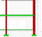
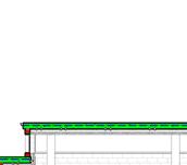


D10-01_Ground Floor Plan 0 D10-02_First Floor Plan 3060 D10-03_Roof Plan 6120 D10-04_Roof Plan 7650 100⌀ OVP
1 13mm PLASTER AND PAINT
100 ⌀ STUB STACK
Control Joint alone shelf angle

27 28 27 35 10 10 10 10

10 10 10 10 10 100 ⌀ PVC soil pipes @ 1:60

GENERAL NOTES
BUILDER TO CORDATE ALL DIMENSIONS/LEVELS/BLD.LIN ES /BLD RESTRICTION LINES FINISHES & SPECS. TO BE CHECKED AND COORDINATED BY THE BUILDER BEFORE ORDERING OR PUTTING ANY WORJK TO HAND ALL SERVICES TO BE COORDINATED BY THE BUILDER BEFORE COMMENCING WORK ENGINEER TO CO-ORDINATE ALL GROUND BEAM LEAVELS , STEP & FLOOR LEVELS NEFORE ANY WORK IS COMMENCED WITH
SECTION NOTES
• POLYRETHENE SEALANT WITH 20MM
• D.P.C. TO WINDOW AND SILLS
• CONC,LINTLE ABOVE WINDOW
• ALL FOUNDATION AND CONCRETE SLABS TO BE ENG. SPEC.
• VERTICAL DPC TO ALL AREAS UNDER NATURAL GROUND LEVEL

• ALL WATERPROOFING BY SPECIALIST
D10-03_Roof Plan 6120








D10-02_First Floor Plan 3060
D10-01_Ground Floor Plan 0
STREET BOE CILL BOE CILL 13mm PLASTER AND PAINT NGL 915 1190 FLAT CONCRETE ROOF WITH SILVER BITUMINOUS COATING Front yard Permable concrete pavers existing vegetation 100 ⌀ FBO DOWNPIPE Scale


by Drawn by Date Project number

2 3 4 103 m² D10-01_Ground Floor Plan Workshop 1 Polished screed 125mm 125mm gutter 255mm CONCRETE ROOF WITH SILVER BITUMINOUS COATING 8 18 1 24 10 27 45 m² D10-02_First Floor Plan Confrence Room 21 Ceremic tiles 77 m² D10-01_Ground Floor Plan Group discussion area 5 Ceremic Tiles Balcony 30m2 150mm Below First Floor Cermic Tiles 1000mm High Steal Balustrade and 50mm Handrail Concrete Monolithic Staircase 16 Risers @ 180mm 250mm tread lanidning to eng. spec 1000mm High Steal Balustrade with glass panels and 50mm ⌀ Handrail concrete lintle 150mm x73mm pre-stressed 427 225 225 7760 8322 6087 912 1715 402 5358 1702 128 820 303 Polyrethene sealant with 20mm polythylene backing board Polyrethene sealant with 20mm polythylene backing board Polyrethene sealant with 20mm polythylene backing board 360 x360mm concrete column cladded with brick and plaster Metal Profiles Coated with Wood Veneers 30 x 30mm metal L brackets bolted into the concrete with 30 x30mm metal T profile bolted to profile wood cladding screwed onto the Tprofile 1000mm High Steal Balustrade with glass panels and 50mm ⌀ Handrail 900 300 mm Concrete retaining wall to eng.spec 900 300 300 x900mm R.C strip foundation @ min 15mPa @28 days to Eng. spec Graded and poisned compacted fill @ max layers of 150mm 375μm DPM 75mm concrete surface bed 20 Mpa @ 28 days
D10-04_Roof Plan 7650 A B C D E F G H NOTES 250mm CONRETE ROOF TO ENG. DETAILS & SPEC GRADED TO FALL TO FULLBORE OUTLETS AT MIN. FALL 1:80 WATERPROOFING TO SPECIALIST DETAIL 2000 REFUSE AREA [PIKITUP AREA]
KERK
Checked
Location: South Africa, Northern Cape Sutherland Latitude/longitude: 32°23'45.3"S, 20°39'43.7"E; Altitude: 1,461m
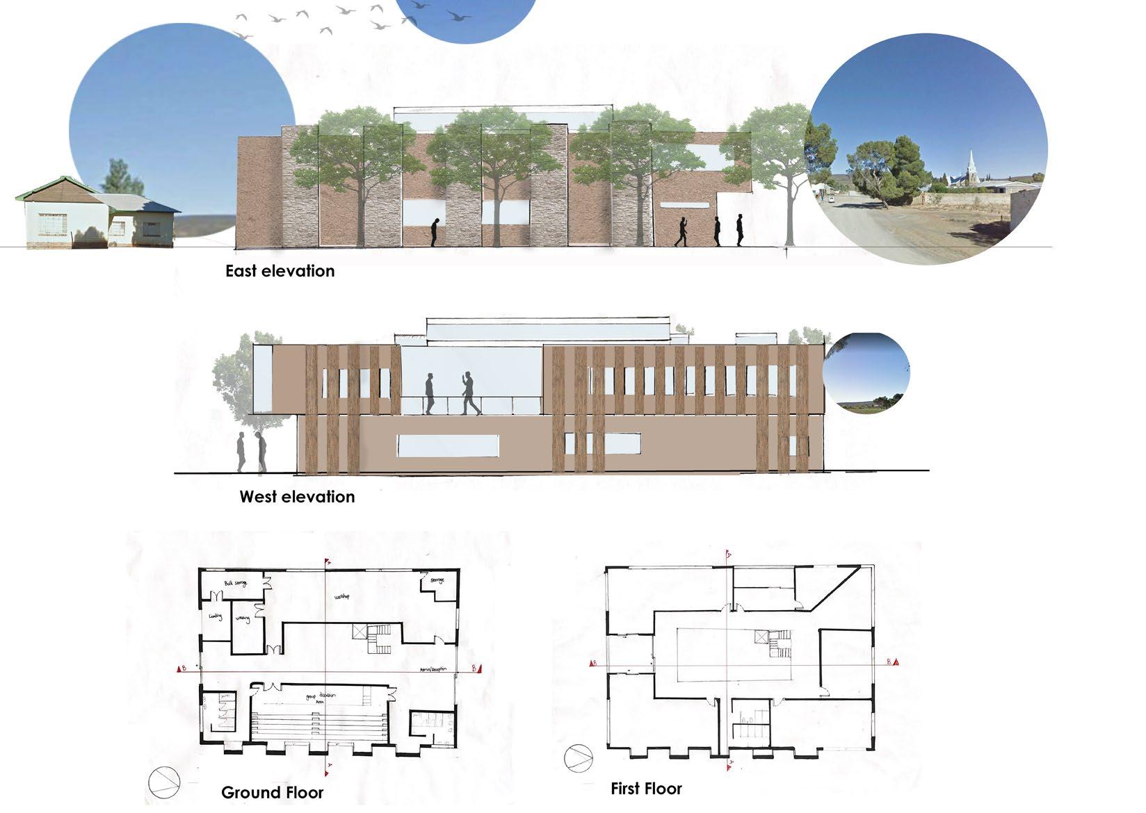
1 : 100 2020/11/06 08:50:47 C03_Elevation 2.2 INNOVATION HUB Green 12/08/2020 Author Checker A3 1 : 100 C20-01_Section A-A 1 1 : 100 D30-03_East Elevation 2
POLYTHYLENE BACKING BOARD
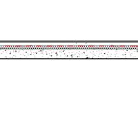
Roof membrane Paraplast 'S' 4mm Screed 30mm with a fall of 1:80


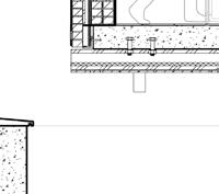
Insulation EPS 30mm










14
4
D10-01_Ground Floor Plan 0 D10-02_First Floor Plan 3060 D10-03_Roof Plan 6120 D10-04_Roof Plan 7650
900 300 1744 645 1436 979
300x300mm ceremic tiles on 10mm tile adhesive with 3mm grounting joint GRADED & POISONED COMPACTED FIIL IN LAYERS OF A MAXIMUM OF 150mm 900 300mm R.C STRIP FOUNDATION @ MIN 15Mpa @28 DAYS TO ENGINEER'S SPEC FOR THE OUTER WALLS
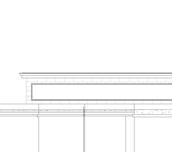
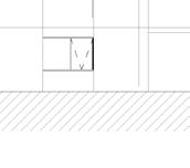
300x300mm ceremic tiles on 10mm tile adhesive with 3mm grounting joint weephole Weak concrete infill 10Mpa @ 28 days 170 X 90mm Meranti External window cill Metal Profiles Coated with Wood Veneers 30 x 30mm metal L brackets bolted into the concrete with 30 x30mm metal T profile bolted to L profile wood cladding screwed onto the Tprofile Steel
Bolted
15 Sealant
rod
concrete
Drainage Chanel SCALE 1:50 SCALE 1:25
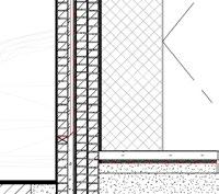
Vapour Barrior polyethylene plastic 6mm Brick standard size 110x75x220mm with 10mm mortar joint Insulation EPS 30mm Cavity 30mm 2-coat Exterior Plaster Precast Cncrete lintle 106 x73mm Precast Cncrete lintle 150 x73mm Aluminuim window-Fixed Jamb Frame Concrete slab 75mm cast-in-situ @ 20 Mpa @ 28 DAYS .TO ENGINEER'S Spec Insulation EPS 30mm DPM Polyethylene 250μm Sand Blinding 50mm
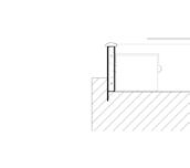
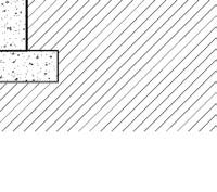
Granular backfill 200mm wide 25mm nomial diameter Sleeved weepholes 75mm ⌀ PVC PCC Weathered stone coping Concrete Retaining Wall 300mm
Concrete slab 75mm cast-in-situ @ 20 Mpa @ 28 DAYS .TO ENGINEER'S Spec
Shelf Angle 90 x90 mm 10mm thick
to concrete
and backer
Precast
Lintles 106x73mm & 150x73mm 3 Quarter Bat Brick Lintle Concrete coping Polyrethene sealant with 20mm polythylene backing board
