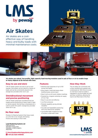
Air skates are a costeffective way of handling heavy and bulky loads with minimal maintenance costs.
Easy to use and store
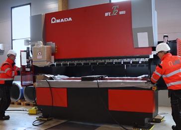
Air skates are robust, low profile, high capacity load-moving modules used in sets of four or six to enable large or heavy objects to be moved with ease.
Features
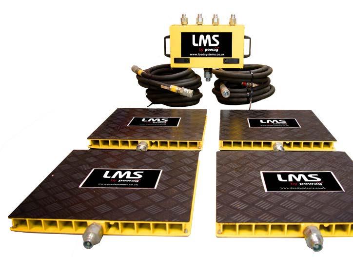
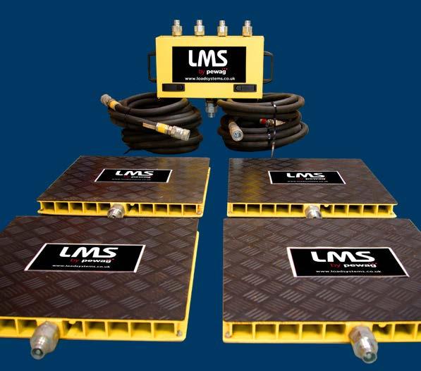
LMS Air Skate systems are easy to set up and operate. One system can be used for a variety of loads, and can be conveniently placed in the storage box provided when not in use.
Omnidirectional movement and precise positioning
LMS Air Skate systemsare omnidirectional and enable precise positioning of heavy loads in tight or narrow spaces. Normal shop compressed air is used to power the system. storage box provided when not in use.
No floor wear
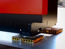
odular ir earing ste s float hea loads on a thin fil of air irtuall eli inating friction and causing no floor wear.
Load Monitoring Systems Ltd Claymore Drive, Aberdeen Energy Park, Aberdeen, United Kingdom, AB23 8GD.
• Working load capacities of up to 100 tonnes and higher
• Move loads in restricted areas where forklifts/cranes cannot reach
• Easy to set up with quick release couplings
• Powered by a regular workshop air supply of 5 to 7 bar
• Easy to use and cost effective
• ow floor pressures
• Modular capability giving ultimate versatility
• Accurate and repeatable positioning with omni-directional capability
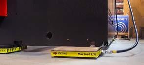
• ow profile s ate odules for ease of location underneath loads
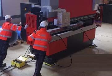
How they Work
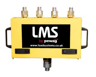
The air skates are connected with a hose manifold and supplied with compressed air. With the air turned on, the flow to each air s ate is regulated to accommodate the load and floor conditions, allowing the load to e lifted clear of the floor.
Modular Air Bearing System (MLS)
TECHNICAL INFORMATION for a 4-module system
1) A’ refers to standard plastic support bars under the control unit. Other features are available under ‘Options’ below.
2) The modules must be placed under the load so that each one sees no more than one quarter of the full system capacity.
3) Thesefiguresrefer to goodfloorconditions, i.e. power-trowelledandsealedconcretesurfaces.