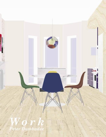
Work Peter Dumbadze
Contents 1. RĂŠsumĂŠ
Professional Work 2. TriBeCa Loft 3. Seven Grams Caffe 4. Brooklyn Brownstone
Competitions
Peter Dumbadze (b. 1987, Cincinnati, OH) is a 2015 graduate of the three year Master of Architecture degree program at the University of Michigan Taubman College of Architecture and Urban Planning. Before attending school in Michigan, he earned his undergraduate degree in art history from Kenyon College in Ohio, where he researched and wrote about the debates concerning the design of contemporary art museums in the post-white cube era. Following graduation, he has worked as a designer for Studio Christian Wassmann, David Cunningham Architecture Planning, and vonDALWIG in New York City. He has also served as a contributing editor to the Brussels-based TL Mag publication.
5. Grand Rapids Automaton
Academic Work 6. Speleology House
All designs, images, drawings, and ideas are the intellectual property of their respective owners.
Peter Dumbadze US Citizen
vonDALWIG (formerly known as Manifold Architecture Studio), Brooklyn, NY Project Designer and Project Manager, April 2018 - December 2018 Design development, schematic design, construction documents High-end residential, high-end commerical, coffee shops David Cunningham Architecture Planning , Brooklyn, NY Project Designer and Project Manager, April 2016 - March 2018 Design development, schematic design, construction documents Brownstone renovations, multifamily social housing, co-op renovations TL Magazine, Brussels, BE/New York, NY Freelance writer-at-large for print and web January 2016 - May 2017, Architectural criticism University of Michigan, Ann Arbor, MI Graduate Student Instructor Faculty Supervisor: Assoc. Prof. Lydia M. Soo “History of Architecture, I” ARCH 313, August - December 2014
skills Software Rhinoceros 3D Adobe Illustrator Adobe InDesign Microsoft Word AutoCAD Laser Cutting Zünd Cutting System Adobe Muse Adobe Premiere Pro Adobe Photoshop PowerPoint Revit 2019 SketchUp VectorWorks
Studio Christian Wassmann, New York, NY Designer , January - May 2012; September 2010 - April 2011 Design development, schematic design, project and construction management, managing interns, model making Exhibition design, small-scale offices, high-end residential
Excel
education
Maya
University of Michigan, Ann Arbor, MI Master of Architecture , May 2015
Analogue
Kenyon College, Gambier, OH Bachelor of Arts Art History, High Honors, May 2010
Novice
employment
ArcGIS VRay CNC Milling Mudbox
Writing Model Making Copy Editing Curating Wood Working
NCARB Active ARE and AXP (IDP) records
Sewing
awards
references
Storefront TV, New York, NY “What About the Grid?” Writer and director for pilot episode chosen for second season of Storefront TV Storefront for Art and Architecture, January 2015 Working as Bar Studio with Derek Chang, Dustin Murphy, and Young-Tack Oh Exhibited June 2015 54Jeff, Grand Rapids, MI Grand Rapids Automaton Third Prize and Student Winner, $3000, SiTE:LAB, 54jeff.org, September 2013 Exhibited September-October 2013
Advanced
496 Henry St, Apt 2 Brooklyn, NY 11231 mail@peterdumbadze.com peterdumbadze.com 513.509.2759
MIG Welding
Available Request Christian Upon Wassmann, Principal Studio Christian Wassmann e. mail@christianwassmann.com David Cunningham, Principal David Cunningham Architecture Planning e. david@dcapny.com Christian Stayner, Principal Stayner Architects e. christian@staynerarchitects.com
5
TriBeCa Loft
Renovation David Cunningham Architecture Planning Architect: D. Cunningham Project Designer and Manager: P. Dumbadze
TriBeCa New York, NY July 2016 - February 2018 Completed Size: 900 SF
7
NOTES
patch
9.90 closet 11.33 ventless partition drop ceiling 22.44
±5'-5"
CL CL
2 1 3 4
A.2
3
12
2 3
A-402.00
align with beam 5|A-500 above
1|A-500 1 2 3
10
S CL
95.3 sf
CL
5
CL
CL
If provided, curbs in shower stalls 36 in by 36 in (915 mm by 915 mm) shall be no higher than 1/2 in (13 mm). Shower stalls that are 30 in by 60 in (760 mm by 1525 mm) minimum shall not have curbs.
NOTES
A
2
A.2
2.10
soffit at beam
2.10
niche spaces
direction of wood floor direction of wood floor (existing) (existing)
4
2 1 3 4
11
6
23.38 recirculating hood
align with beam 5|A-500 above
1|A-500 1 2 3
4 S
10
S
A-401.00
CL CL
5
±18'-0"
±18'-0"
01
4
direction of wood floor (existing)
02
08
07 03 04 05
L/D L/D 05 05 467.9 sf 498.9 sf LIGHT + AIR LIGHT + AIR 46.7 23.4 reqd 49.8 24.9 147.7 73.873.8 prvd 147.7
LIGHT + AIR 46.7 23.4 147.7 73.8
reqd prvd
Existing Floor Plan Scale: 14" = 1'-0"
1
wanted to open up their TriBeCa loft, so as to take full advantage of the large windows. Selectively removing excessive partitions,
06
Existing Floor Plan Proposed Floor Plan 1 " = 1'-0" Scale:Scale: 1 " = 1'-0" 4 4
UNIT 9A
soffit
9.21
#
9.64
1
patch
2
01 02 03 04 05 06 07 08 09 10 11 12 TOTAL:
WxH 2'-9" x 7'-2 12" 2'-9" x 7'-2 12" 3'-9" x 7'-2" 3'-9" x 7'-2" 3'-9" x 7'-2 12" 3'-9" x 7'-2" 2'-4 12" x 8'-2" 4'-4" x 8'-2" 2'-4 12" x 8'-2" 2'-5" x 8'-2" 4'-4" x 8'-2" 2'-4" x 8'-2"
Glass Area 19.82 sf 19.82 sf 26.88 sf 26.88 sf 27.03 sf 26.88 sf 19.40 sf 35.39 sf 19.40 sf 19.74 sf 35.39 sf 19.06 sf 295.69 sf
05
L/D
6.40
498.9 sf
9.21
LIGHT + AIR 49.8 24.9 147.7 73.8
Window Analysis
9.22
KEY PLAN
±34'-5"
niche spaces 2.10 6.40
9.90
The clients, a landscape architect-turned-financier and a doctor,
KEY PLAN
±34'-5" ±34'-5"
±34'-5"
prvd
Where partitions are to b removed, care shall be take to make sure there are n risers serving other apartmen contained within.
No decrease in the soun rating of the floor shall b allowed. The sub floor may no be removed. The sam thickness (or thicker) o materials for the new floorin must be maintained.
09
A-401.00
08
06
reqd
NOTES
A-401.00
05
niche spaces soffit
HVAC
3|A-500
04
2.10
A
A-402.00
A.2
1
4|A-500
03
L/D
3
A-405.00
07
467.9 sf
lavatory toilet shower tub washing machine waterproof pan w/ sensor for shut-off valv 22.50 sink 22.51 dishwasher 22.52 gas range
12 ex. risers
01 to 95.3 Where partitions are be sf removed, care shall be taken to make sure there are no risers serving other apartments contained within. No decrease in the sound rating of the floor shall be allowed. The sub floor may not be removed. The same thickness (or thicker) of materials for the new flooring must be maintained.
09
02
05
22.40 22.41 22.42 22.43 22.44 22.45
2 1 3
±18'-0"
±11'-0"
01
±11'-0"
±11'-0"
direction of wood floor (existing)
CL
DW
F
W/D
4|A-502 i EP
±11'-2"
PLUMBING 6|A-500
ventless
HALL
A-401.00
exhaust
11.30 refrigerator 11.33 electric ventless dryer
A-400.00
S CL
22.45
4 S
To the best of my knowledge, proper inspection, probing and/or evaluation of the existing conditions have been performed, by myself, to ensure that the alteration design will not cause the damage to, disruption of, the relocation and/or modification to any structural element including slabs and columns, plumbing risers, intercom risers, phone risers, electrical risers and/or ventilation chases/ducts. In the event unexpected conditions are uncovered and/or the alteration plans must be modified in any way, the Shareholder and/or their contractor must notify Building Management prior to proceeding further.
01.13.17 01.03.17 12.19.16 11.29.16 10.20.16 10.05.16 09.27.16 08.26.16
dc
UPDATED DRAWING SET, 4 UPDATED DRAWING SET, 3 UPDATED DRAWING SET, 2 UPDATED DRAWING SET UPDATED BIDDING SET, 2 UPDATED BIDDING SET BIDDING SET DRAWING SET
reqd
9.22
prvd
9.64 9.90
UNIT 9A Window Analysis
# patch
4 of 6
ap pllc
david cunningham architecture planning 543 union st, 1c brooklyn ny 11215 718 208 0815 www.dcapny.com
01 02 03 04 05 06 07 08 09 10 11 12 TOTAL:
WxH 2'-9" x 7'-2 12" 2'-9" x 7'-2 12" 3'-9" x 7'-2" 3'-9" x 7'-2" 3'-9" x 7'-2 12" 3'-9" x 7'-2" 2'-4 12" x 8'-2"
Glass Area 19.82 sf 19.82 sf 26.88 sf 26.88 sf 27.03 sf 26.88 sf 19.40 sf 35.39 sf 19.40 sf 19.74 sf 35.39 sf 19.06 sf 295.69 sf
To the best of my knowledge, proper inspection, probing and/or evaluation of the existing conditions have been performed, by myself, to ensure that the alteration design will not cause the damage to, disruption of, the relocation and/or modification to any structural element including slabs and columns, plumbing risers, intercom risers, phone risers, electrical risers and/or ventilation chases/ducts. In the event unexpected conditions are uncovered and/or the alteration plans must be modified in any way, the Shareholder and/or their contractor must notify Building Management prior to proceeding further.
01.13.17 01.03.17 12.19.16 11.29.16 10.20.16 10.05.16 09.27.16 08.26.16
dc
2
4'-4" x 8'-2" 2'-4 12" x 8'-2" 2'-5" x 8'-2"
Existing and Proposed Floor Plans
CASA A | R-V
4'-4" x 8'-2" 2'-4" x 8'-2"
board and City approvals, and renovation process.
100 Hudson Street, Apt 9A New York, NY 10013
ap pllc
A-100.00
primary contact and helped administer the design, bidding, co-op
A-100.00
UPDATED DRAWING SET, 4 UPDATED DRAWING SET, 3 UPDATED DRAWING SET, 2 UPDATED DRAWING SET UPDATED BIDDING SET, 2 UPDATED BIDDING SET BIDDING SET DRAWING SET
david cunningham architecture plan 543 union st, 1c brooklyn ny 11215 718 208 0815 www.dcapny.com
From the start of the project until completion, I was the client’s Proposed Floor Plan Scale: 14" = 1'-0"
Existing and Proposed Floor Plans
CASA A | R-V 100 Hudson Street, Apt 9A New York, NY 10013
we are able to create not only a larger bathroom and kitchen, but also let natural light reach back into these spaces. Maintaining a minimalist aesthetic inspired by Donald Judd and Tony Smith, the custom millwork is assertive, yet does not shout.
8
salvage item remove item light gauge framing millwork damp + waterproofing door gypsum board tile ceilings wood flooring paint
A
2.10
niche spaces
±8'-3"
3 1 2
A
2.10
soffit at beam
±7'-7"
pan, sensor, and valve beneath fridge
22.44
CURBS (ANSI 4.21.7) :
n by 36 in than 1/2 in 60 in (760 e curbs.
LIGHT + AIR 14.2 7.1 147.7 73.8
prvd
±6'-6"
5.40 22.44 washing machine 22.45 waterproof pan6.40 w/ sensor for shut-off valve 7.10 22.50 sink 9.29 22.51 dishwasher 22.52 gas range 9.64 patch
Following Spread: Early proposal for kitchen and 11 9.90 HVAC living room 11.33 23.38 recirculating hood 1
A-405.00
closet
47.3 sf
A.1
118.9 sf
30"x48" clear (fig 32) 48"x56" clear (fig 28) 36"X48" clear (fig 35)
2.10
04 BEDROOM 142.9 sf
BATH
reqd
direction of kitchen wood floor over waterproofed area (new)
3|A-500
6
03
A.1
HALL
HALLHALL 01 01 118.9 sf
ex. ex. risers risers
1
4|A-500
2
A.2
A.1
ANSI NOTES:
CLEARANCES: 1. LAVATORY 2. TOILET 3. SHOWER
4|A-502 i EP
9.90
ARCHITECTURE
2.05 2.10 5.40 6.40 7.10 8.14 9.29 9.30 9.50 9.64 9.90
APPLIANCES
22.40 lavatory This Page: Proposed reno22.41 toilet 22.42 shower vations, not to scale 22.43 tub CL
A.1
2.1022.45
EP i
6|A-500
DW
F
W/D
22.43
47.4 sf
±11'-2" ±11'-2"
A-400.00
S CL CL
9.90
PLUMBING
exhaust
DW
9.29
±12'-9"
9.29
pan, sensor, and valve beneath fridge
22.42
02 KITCHEN
Left: Existing conditions and demolition plan, not to APPLIANCES 11.30 refrigerator scale 11.33 electric ventless dryer
±8'-3"
9.64
±3'-2"
9.64
EP i
2.10
01
15) Absolutely no penetration of the existing concrete slabs will be permitted.
±5'-5"
closet partition drop ceiling
142.9 sf
LIGHT + AIR LIGHT AIR reqd 14.2 7.1+7.1 reqd 14.2 prvd 147.7 73.8 prvd 147.7 73.8
8.14
±18'-0"
CL
exhaust
±4'-2"
of the mitted.
7.10
±7'-6"
F 3 1 2
6.40
14) Hard Surface Floor Finish Requirements must be complied with. ±12'-9"
ex. risers
±7'-7" ±7'-7"
5.40
±3'-0"
closet
±10'-1"
±10'-1"
2.10
13) It is mandatory to close off all existing vents and louvers during construction to avoid dust infiltration into other apartments.
direction of kitchen wood floor over waterproofed area (new)
±10'-11"
exhaust
DW
Finish
r (fig 32) r (fig 28) ar (fig 35)
±6'-6" ±6'-6"
12) Prior to proceeding with the partition openings and changes, probe to locate the utilities and existing structures. F
BEDROOM 04 BEDROOM 04 142.9 sf
6.40
22.41
glass backsplash
2|A-500
±11'-2"
±3'-2"
with.
47.4 sf
11) No penetration of existing shafts will be permitted and no relocation of the risers will be allowed.
partition ocate the
ll existing uction to o other
flooring
X-BATH BATH 03 03 34.5 sf 47.3 sf
02 KITCHEN 0242.4KITCHEN sf
salvage item NOTES: remove item 1) All bathroom fixtures are light gauge framing handicapped accessible. millwork damp + waterproofing 2) Provide blocking in wall for door future installation of required gypsum board grab bars tile ceilings wood flooring paint
5.40
22.40
9.34
closet dishwasher electrical panel fridge / freezer washer/dryer smoke/co2 detector
floor + wall
2|A-500
±7'-6"
9.29 pocket door, glass block partition 2.10 9.90
22.42 fixtures, door, 2.1022.43 drop ceiling, partition,
drop ceiling, partitions, flooring
2) Provide blocking in wall for future installation of required grab bars
2.05 2.10 5.40 6.40 7.10 8.14 9.29 9.30 9.50 9.64 9.90
±10'-11"
±7'-7"
9.64 appliances, cabinets, 2.10 9.90
10) No vibrating or electrical hammers are to be used.
fts will be the risers ±6'-6"
8.14
9.29 9.30
9.29
ARCHITECTURE
±3'-0"
mers are
22.41
7.10 8.14
9.90
±4'-2"
9) No vertical risers will be moved or relocated.
LIGHT + AIR reqd 14.2 7.1 prvd 147.7 73.8
6.40
A
moved or
22.40
±12'-9"
142.9 sf
9.29
CL DW EP F W/D S
5.40
7.10
±3'-2"
8) All ventilation ducting penetrating fire rated construction is to be provided with fully accessible fire and smoke dampers.
04 BEDROOM
03 X-BATH 34.5 sf
42.4 sf
2.10
pocket door, glass block partition
5.40
2|A-500
2.10
02 KITCHEN
fixtures, door, drop ceiling, partition, flooring
9.90 glass backsplash
closet dishwasher electrical panel fridge / freezer washer/dryer smoke/co2 detector
floor + wall
2|A-500
2.10
ating fire ded with mpers.
appliances, cabinets, drop ceiling, partitions, flooring
9.29 9.30
7.10 9.34 NOTES: 1) All bathroom fixtures are handicapped accessible.
8.14
±3'-2"
7) All building system ventilation ducting installed within shaft wall construction to maintain a 2 hour fire rating and be fully firestopped.
7.10
±12'-9"
6) Refrigerator and washer to have drip pan, water sensor and shut off valve installed underneath the units
CL DW EP F W/D S
5.40
ADA clear floor area
NOTE: Kitchen cabinetry and fixtures to be provided by others; installation to be done by contractors. 5.40
A
5) Kitchen to have recirculating exhaust
n ducting uction to d be fully
ADA clear floor area
NOTE: Kitchen cabinetry and fixtures to be provided by others; installation to be done by contractors. 5.40
4) Dryer to be ventless
have drip off valve
waterproof membrane
waterproof membrane
3) Maintain existing heating system
haust
new partition
new partition
2) For wall, floor, ceiling, and shaft assembly details, see drawing A-500.00
nd shaft 00.00
demolition
demolition
±11'-0"
dproofing
LEGEND
LEGEND
1) For waterproofing and soundproofing details, see drawing A-500.00
9
10
Larger upper cabinets sit 2’ above counter top space.
11
New linen closet is millwork that melds into low-slung sh that doubles as a bench.
9.64
2
Left: Kitchen elevation 1|A-400, 1/2” 7'-8" = 1’
8.14
22.50
F.2
G.2
H.2
2'-3"
2'-1"
2'-3"
2'-4"
9'-7"
6'-9"
1'-10"
1'-10"
4|A-503
6" 5"
6'-8"
6|A-502
hinged
9'-7"
2'-4"
23.38
2'-6"
8'-5 7/8" 2'-2"
1"
22.51
ep
intercom
align 1"
22.52 5'-6"
2'-2"
±1'-3"
1'-3"
11.30
9.90
9'-7"
9.29
5.41 9.29
1'-1"
9.90
1'-10"
1'-5 7/8"
5|A-502
4'-5"
Right: Kitchen elevation 3|A-400, 1/2” = 1’
5.41
±1'-1"
align
±1'-3"
11'-4"
4"
6"
1'-1"
6"
3'-0"
3'-0"
3'-0"
2'-5"
align to fridge panel
4"
Elevation " = 1'-0"
1
2'-6"
2'-2"
2'-2"
A refrigerator
B
C
2'-5"
2'-0"
2'-5" 4'-10"
1" 1 3/8"
2"
7.10 9.64
Kitchen Elevation Scale: 12" = 1'-0"
10" 2'-0"
2'-0"
2
Kitchen Elevation Scale: 12" = 1'-0"
D
2'-6"
F.1
2'-0"
G.1
10"
E
1"
2'-0"
3'-0"
H.1
J.1
1/4" 2"
3
±
±1'-2"
12
13
align
±1'-3"
H.2
2'-3"
2'-1"
2'-3"
1"
2'-4"
G.2
2'-4"
1"
F.2
9'-7"
hinged
1'-10"
2'-6"
6'-9"
4'-10"
4"
1'-1"
3'-0"
6"
6" 5"
2"
4|A-503
2'-0" 1 3/8"
Kitchen Elevation Kitchen elevation 1 Scale: 2|A-400, 1/2” = 1'-0" 1’ 2" =
2'-0"
2'-0"
2'-0"
3'-0"
F.1
G.1
H.1
J.1
1/4" 2"
3
±7'-7" ±1'-2"
14
±4'-5"
1'-1"
15
Left: The existing hallway during probing; blue tape marks out where proposed walls are to go Right: The hallway under construction; bathroom framing underway
16
17
7.10 9.21 9.22 9.30
Rerouted Duct
6'-3"
1'-8"
3'-0"
2'-1"
4'-3"
1'-7" 6'-3"
9.29
7.10
7"
7"
7.10
7 1/2"
1'-10"
4'-3"
Rerouted Duct
22.42
Left: Bathroom elevation 1|A-405, 1/2” = 1’ Rerouted Duct Right: Bathroom elevation 2|A-405, 1/2” = 1’
9.30
9.2
9.50
9.50
9.3
22.42
22.42
9.5 5'-11"
6'-0"
8'-5"
9'-0"
2'-6"
1'-5"
3"
2 A501
9.2
1'-5"
2'-9"
9.2
1'-5"
3'-0"
2'-9"
2 A501
3"
2'-6" 1'-11"
3'-4"
1'-7"
±6" ±4"
1'-4"
8'-4" 7'-8"
9'-0"
8'-11 7/8"
3'-3"
5 A501
5'-5"
9.30
6'-0"
7.1
6'-0"
9.29
9.3
22. 5"
3'-0" 6 1/2"
2'-9"
7'-0" 3'-0"
4'-0"
3" CL CL shower head and controls toilet 22.41 wall-mounted
6.40
18
22.40 1
2
1'-8 1/4"2'-9"
5" 6 1/2"
10.28 Bathroom Elevations Bathroom Elevations 1 1 2" = 1'-0" Scale: Scale: 2" = 1'-0"
6"
vanity
7.10
medicine cabinet
9.21 9.22 9.30 22.43
3'-11"
7'-0"2'-8"
3" CL shower head and controls
7.10
6 A501
Bathroom ElevationsBathroom Elevations Scale: 12" = 1'-0" Scale: 12" = 1'-0" 3
9.30
CL tub faucet
5"
7.10 9.21 9.22
2
9.30 22.4319
1
Scale: 12" = 1'-0"
7.10 9.21 9.22 9.30
Rerouted Duct
4'-3"
6'-3"
1'-8"
3'-0"
2'-1"
1'-7"
Right: Bathroom elevation 4|A-405, 1/2” = 1’
7"
7.10
22.42
Left: Bathroom elevation 3|A-405, 1/2” = 1’
1'-5"
9.29 9.30 9.50
1
8'-5"
5'-5"
3'-3"
8'-5"
9'-0"
7'-0" 5'-11"
6'-0"
22.42
3"
2'-9" 6 1/2"
7'-0"
3" CL shower head and controls
7.10
20
9.22 2
2'-10" 1'-8 1/4"
5"
9.21 Bathroom Elevations Scale: 12" = 1'-0"
9.30 22.43
2'-8" 3'-11"
1'-7"
2'-10" 2'-8"
7.10
6 A501 Bathroom Elevations Bathroom Elevations 1 Scale: 2" = 1'-0" 3 Scale: 12" = 1'-0"
1'-5"
9"
2 A501
1'-5"
1'-5"
2'-6"
2'-9"
3'-9"
1
9.30 4 21
Left: Demolition Right: Bathroom partition complete Following Spread: Millwork detail drawings for kitchen pantry
22
23
GWB to soffit
LE
1'-5 7/8"
1'-5 7/8"
1'-5 7/8"
millwork
5/8"
fry reglet z reveal drmz-625-625
fixed shelf
Kitchen Pantry Reveal Detail, Section Scale: 3" 6" = 1'-0"
Hafele "Tab" pull 126.14.901
5
Hafele Box Milano 443.17.107
1 8"
2'-1 5/8"
overhead door track
reveal
countertop
fixed shelf
6'-8"
6'-8"
2'-1 5/8"
8'-5 7/8"
reveal
pantry panel
2'-1 5/8"
adjustable shelf
1 8"
pantry panel
reveal
2'-1"
2'-1 5/8"
8'-5 7/8"
8'-5 7/8"
1 8"
8'-5 7/8"
fridge panel
4'-3 3/8"
2'-1 5/8"
2'-1"
2'-1 5/8"
adjustable shelf
Kitchen Pantry Detail, Plan Scale: 3" 6" = 1'-0"
align
fixed shelf
6
Hafele "Tab" pull 126.14.901
Hafele "Tab" pull 126.14.901 1 8"
reveal
NO
reveal
W re to ris co
adjustable shelf
1 8"
1'-2 1/4"
1'-2 1/4"
2'-3"
freezer panel
1'-2 1/4"
1/8"
1 8"
reveal
N ra all be th m m
3/4"
2'-5 3/4"
2"
4"
1'-2"
1/2"
Kitchen Pantry Bay A (fridge) 1 " = 1'-0" Scale: 13/4" 2
2'-1 3/4"
2'-1 3/4"
5"
7
4"
4"
4"
4"
Kitchen Pantry Detail, Section Scale: 3" 6" = 1'-0"
1
Kitchen Pantry Bay B, C Section 1 " = 1'-0" 2 Scale: 13/4" 2
Kitchen Pantry Bay B 1 " = 1'-0" Scale: 13/4" 2
3
Kitchen Pantry Bay C 1 " = 1'-0" Scale: 13/4" 2
4 2" 1/8"
24
Kitchen Pantry Detail, Elevation Scale: 3" 6" = 1'-0"
8
25
1
d
Seven Grams Caffe
Build-out of new coffee shop vonDALWIG Architecture Architect: K. von Dalwig and P. von Dalwig Project Designer and Manager: P. Dumbadze Project Designer: S. de Zarraga
76 Madison Avenue New York, NY May 2018 - December 2018 Completed Size: 1,000 SF
27
Left: The finished espresso bar and pastry display case Right: An early axonometric of the proposed space detailing material relationships (drawing by S. de Zarraga)
OPTIONS
7 GRAMS CAFE
28
For many years, Seven Grams Caffe has had a presence west of
Seven Grams approached vonDALWIG to design the new location
Broadway. With a focus on pastries and espresso drinks, the café
and requested that the office execute the design as an update to
found an opportunity to expand east in a new space in the Flatiron
the café’s original location in Chelsea, which vonDALWIG had
District at the intersection of Madison Avenue and 28th Street.
previously designed.
What had previously been the location of a franchise restaurant,
Our design intent was to create a space that was simultaneously
the building’s co-op had gutted the space down to the studs, leav-
open yet cozy, creating a respite from the Midtown hustle. Us-
ing relative room for design freedom.
ing a material palette that mixed plainsawn oak with blackened
29
Left: Axonometric studies (drawings by S. de Zarraga and P. Dumbadze)
±6'-1"
±6'-3"
Right: Proposed floor plan and furniture layout (Scale: 1/8” = 1’-0”)
OPTION 2
6'-2"
3'-0"
3'-1"
±22'-4"
±4'-4"
±8'-0"
DN
BUILT-IN BENCH BY MILLWORKER FOOD PREP 103
abc1 2 3 abc1 2 3
abc1 2 3
abc1 2 3
abc1 2 3
abc1 2 3
abc1 2 3
abc1 2 3
abc1 2 3
abc1 2 3
abc1 2 3
abc1 2 3
abc1 2 3
abc1 2 3
abc1 2 3
abc1 2 3
abc1 2 3
abc1 2 3
abc1 2 3
abc1 2 3
vonDALWIG
vonDALWIG
±35'-0"
7'-1"
ESPRESSO BAR BY MILLWORKER
±8'-1"
±19'-4"
OPTION 4
±44'-8"
7 GRAMS CAFE
ADA RESTROOM 102
5'-0"
abc1 2 3
abc1 2 3
abc1 2 3
abc1 2 3
abc1 2 3
abc1 2 3
abc1 2 3 abc1 2 3
abc1 2 3
abc1 2 3
abc1 2 3
abc1 2 3
abc1 2 3
abc1 2 3
abc1 2 3
OPTIONS
abc1 2 3 abc1 2 3
±6'-9"
abc1 2 3 abc1 2 3
±14'-2"
abc1 2 3
TAKEAWAY COUNTER
±4'-2"
CAFE 101
vonDALWIG
vonDALWIG
7 GRAMS CAFE
±6'-9"
±6'-8"
±8'-7"
±3'-6"
±31'-0"
vonDALWIG
7 GRAMS CAFE
abc1 2 3 abc1 2 3 abc1 2 3 abc1 2 3 abc1 2 3 abc1 2 3 abc1 2 3 abc1 2 3 abc1 2 3 abc1 2 3
30
vonDALWIG
31
steel, the contrast in colors help to break down the otherwise large space into a smaller scale. On the technical side of the project, we designed a back of house that would anticipate the café’s change from doing only baking on site to also doing future lunch service.
Left: South proposed elevation (Scale: 1/8” = 1’-0”)
ager for vonDALWIG, would directly interact with the client and
Right: West proposed elevation (Scale: 1/8” = 1’-0”)
ment. In our scope of work that included space planning and de-
millworker, leading design and construction document developvising the look and feel, we also provided detail drawings for the
With a fast-track schedule, there was an aggressive period of
espresso bar, benches, some of the table tops, and the partition
design and construction document production. While the client
that divided the restroom’s hallway from the café space.
would handle construction administration, I, as the project man-
32
33
Left: Axonometric of the new bench (Not to scale) Right: Detail drawing of the espresso bar
1 4"
LG HI-MACS M104 ROMA AHDERED TO 21" SUBSTRATE
HUDSON COMPANY BARE, RECLAIMED WHITE OAK FLAT SAWN, POLY
3 4"
2"
HUDSON COMPANY BARE, RECLAIMED WHITE OAK FLAT SAWN, POLY (4" X ±43") OVER 12" PLYWD SUBSTRATE. MOUNT PLYWD TO 1 12" S.S. FRAMING
4"
SPAN S.S. SHELF BETWN FRAME
1 12" S.S. FRAME (HORIZ & VERT) ADD LEVELERS TO LEGS
4"
3 4" Ø BLACKENED STEEL TUBE SUPPORT. ALIGN SUPPORT O.C.
EXISTING FLOOR; PATCH AS NECESSARY
443"
3"
LG HI-MACS M104 ROMA AHDERED TO 21" SUBSTRATE
3 4"
1 4"
03 SECTION DETAIL - COUNTER 3" = 1'-0"
34
35
Brooklyn Brownstone
A Gut Renovation of a Brownstone for a Growing Family David Cunningham Architecture Planning Architect: D. Cunningham Project Manager: P. Dumbadze Project Designer: J. Cummings
Carroll Gardens Historic District Brooklyn, NY November 2017 - ongoing In Construction Documents Size: 4,100 SF
37
Located on a leafy cross street in a historic section of Brooklyn’s Carroll Gardens neighborhood sits an empty house. Forlorn and unloved, the brownstone had seen its transformation from a house for one family into three apartment units. Each floor in the house was an archaeology of the building’s previous lives. Having sat uninhabited for three years, a young couple with a son purchased the property with the intent of rescuing it and modernizing the brownstone to serve as their new home for years to
38
Left and Right: proposals for the master bedroom
come. With an interest in contemporary art and design, they have asked us to create an open, yet cozy space that was clean and devoid of any visual clutter. In their programmatic request, they wanted a rental unit on the ground level, with a triplex on top. Throughout the brownstone, our strategy has been to tuck rooms inside of the poché space, creating a scalar relationship between various rooms in the house, but also allowing us to have the streamline aesthetic. This, coupled with choosing a material pal-
39
Left: The parlor floor bay window during probing inspections Right: In our efforts to convince our clients to go with the floor plan we had proposed for the third floor, we spray painted a one-toone plan on the sidewalk in front of our office. On the other side of the street, we painted an option that we did not favor. In walking our clients through the two options, they were able to understand the spatial benefits of our favored plan.
ette that utilized the warm, woody tones and strong, saturated colors, would become the project’s conceptual framework. In order to convince the clients of these design decisions, we had to go beyond orthographic drawing. Whenever the couple hesitated or had internal disagreement about how to proceed with a layout or a detail, we did one of two things: create a visual representation of the space that erred on the didactic side, and create one-to-one mock ups of the floor plan options for them to phys-
40
ically experience. It was through these less-than-conventional methods that we were able to guide them through the design’s development During my time on this project, I worked directly with the clients. I managed the development of the design, working with my project designer, preparing renderings for presentations with clients, as well as collaborating directly with the MEP and structural engineers.
41
7.21
8.10
9.90
9.20
9.22
9.64
9.90
11.30
8.10
9.20
11.32
22.50
22.51
9.64
9.90
02 KITCHEN 89 sf
01 GARDEN SHED 12 sf
11.33
14'-9"
±4'-4"
patch + repair wall
LEGEND
6.40
remove item
9.22
new partition
06 HALL 48 sf
22.44 6'-0"
±7'-6"
## 8'-0"
±4'-10"
±6'-11"
door tag
## window tag
B W/D
F
ABBREVIATIONS 03 02 01
CL DN DW F R W/D ±
±6'-0"
DW
DN
10
04
08
A
09 05
2
±16'-6"
02
A-401
5.01 1 4 2 3
CL
2 3 1
06
A-402
±3'-8"
18'-11"
5'-0"
03 LIVE/DINE 207 sf
1
2.10
4.01
C
03
Proposed Basement Plan Scale: 14" = 1'-0"
A-403
2'-0"
04 BATH 51 sf
repair + refinish fireplace
14'-5"
05 BEDROOM 147 sf
8.10
8.50
9.20
8.10
9.20
9.22
8.10
8.50
9.20
9.22
9.64
9.90
9.30
9.90
22.40
9.22
9.64
9.90
22.41
22.42
2.10
partition, door
01
sand + repaint gate ±10'-1"
±16'-9"
deck above
07 1
partitions, doors, stairs
Garden22.40 Floor lavatory 22.41 toilet 1/4” = 1’ 22.42 bathtub
±9'-7"
±5'-5"
22.44 washing machine 22.50 sink 22.51 dishwasher
±12'-3"
HVAC ±4'-10"
UP
±2'-10"
DN
±2'-6"
42
±27'-3" ±7'-0"
salvage item remove item masonry repair metal repair structure steel framing metal decking metal stairs metal railing millwork insulation door window gypsum board light gauge framing ceramic tiling wood flooring paint
PLUMBING
±9'-8" ±4'-4"
2.05 2.10 4.01 5.01 5.12 5.30 5.51 5.52 6.40 7.21 8.10 8.50 9.20 9.22 9.30 9.64 9.90
11.30 fridge 11.32 range 11.33 electric dryer
±47'-9" ±4'-5"
ARCHITECTURE
APPLIANCES
04 X-HALL 132 sf
ROOM 01 X-MUD 36 sf
closet down dishwasher refrigerator radiator washer/dryer verify in field
tbd NOTES
1.
43
6.40
LEGEND
05.12
05.51
8.10
9.20
9.22
05.30
05.52
9.30
22.40
22.41
remove item new partition
RM 03 PWDER 16 sf
01 DECK 174 sf 13'-1"
12'-8"
6'-6"
2'-11"
##
±12'-4"
door tag
## window tag
1
13
1
A-411
A-412
11
12
6.40 wall
A-412
6.40
4.01
repair newel
niche
±16'-6"
2
ABBREVIATIONS ±6'-3"
13
F
UP
DW
UP
1 4 2 3
pantry
12
MW 8'-3" x 3'-6"
14
±10'-4"
15
11
4.01
14
repair+ refinish fireplace
UP ±3'-8"
15'-9"
9'-6"
02 KITCHEN 236 sf
Proposed Parlor Plan Scale: 14" = 1'-0"
1
6.40
8.10
9.20
9.64
9.90
11.30
11.32
22.50
22.51
9.22
17'-0"
LIVING
04 DINING 131 sf
05
9.64
6.40
8.50
9.64
9.90
9.90
269 sf
CL DN DW F MW R W/D ±
closet down dishwasher refrigerator microwave radiator washer/dryer verify in field
ARCHITECTURE
2.05 2.10 4.01 5.12 5.30 5.51 5.52 6.40 8.10 8.50 9.20 9.22 9.30 9.90
salvage item remove item masonry repair structure steel framing metal decking metal stairs metal railing millwork door window gypsum board light gauge framing ceramic tiling paint
APPLIANCES
11.30 fridge 11.32 range PLUMBING
2.10
partitions, door, window, fixtures
04 X-BATH 23 sf ±8'-0"
2.10
doors
2.05
front door
2.10
partitions, basement stairs, radiator
2.10
partition, vestibule door
04 X-HALL 124 sf
22.40 lavatory 22.41 toilet 22.50 sink Parlor22.51 Floor dishwasher
04 X-VEST 17 sf
±6'-4"
±23'-1"
1/4” = 1’ HVAC
±3'-3"
tbd
±5'-4"
UP
1. UP
44
2.05
DN
2'-10"
NOTES R
45
LEGEND
6.40
8.10
9.20
6.40
8.10
9.20
9.22
9.64
9.90
9.22
9.64
9.90
RM 01 BED 152 SF
remove item new partition
RM 04 BED 167 SF 11'-0"
±15'-4"
±2'-11"
##
door tag
12'-2"
23
22
26
23
2
1 3
1 2
1 3
A-421
A-423
A-424
D
1 4 2 3
reinforce wall with plywood backing
24
A-422
W
24
21 25
11'-1"
5'-6"
02
Proposed Second Floor Plan Scale: 14" = 1'-0"
1
2'-2"
BATH 53 SF
closet down radiator washer/dryer verify in field
ARCHITECTURE
seat
2
ABBREVIATIONS
CL DN R W/D ±
27
22
13'-9"
CL
DN
21
2'-0"
linen
14'-4"
CL
UP
2'-0"
## window tag
10'-6"
12'-1"
2.05 2.10 5.12 5.30 5.51 5.52 8.10 8.50 9.20 9.22 9.30 9.90
salvage item remove item structure steel framing metal decking metal stairs metal railing door window gypsum board light gauge framing ceramic tiling paint
APPLIANCES
RM 03 PLAY 108 SF
11.33 electric dryer PLUMBING
8.10
9.20
9.22
6.40
9.64
9.30
9.90
22.40
9.90
11.33
22.41
22.42
22.40 22.41 22.42 22.44
22.44
lavatory toilet bathtub washing machine
HVAC
2.10
partitions, cabinets, appliances, window
01 X-KITCHEN 36 SF ±6'-4"
2.10
partitions, door, fixtures
02 X-BATH 24 SF
2.10
2.10
door
04 X-HALL 111 SF
±12'-2"
UP DN
46
5'-8"
F
tbd
SecondNOTES Floor 1/4” = 1’ 1.
05 X-STUDY 74 SF ±18'-5"
±4'-5"
partitions, door, window
47
6.40
8.10
9.20
6.40
8.10
9.20
9.22
9.64
9.90
9.22
9.64
9.90
RM 01 M BED 219 SF
LEGEND
remove item
04 STUDY 165 SF
new partition
±42'-6" 14'-3"
±10'-8"
##
17'-2"
door tag
## window tag
8.60
31
sand + repaint ladder
32
33
CL DN R W/D ±
2'-7"
DN
33
±3'-1"
ABBREVIATIONS
5.01
closet down radiator washer/dryer verify in field
3 1 2
8.60
1 4 2 3
A-433
34
4.01
4.01
3'-0"
repair fireplace
10'-5"
14'-3"
16'-1"
BATH
02
Proposed Third Floor Plan Scale: 14" = 1'-0"
31
32
repair fireplace
8.10 1
9.20
9.22
9.30
9.90
22.40
22.41
22.42
W.I.C.
salvage item remove item masonry repair metal repair millwork door window skylight gypsum board light gauge framing ceramic tiling paint
22.40 lavatory 22.41 toilet 22.42 shower
40 SF
6.40
2.05 2.10 4.01 5.01 6.40 8.10 8.50 8.60 9.20 9.22 9.30 9.90
PLUMBING
12'-3"
03
71 SF
2'-6"
A-432
±16'-4"
3 1 2 A-431
5'-4"
±16'-4"
ARCHITECTURE
9.20
HVAC
tbd NOTES
2.10
cabinets, appliances, window
01 X-KITCHEN 44 SF
±6'-6"
2.10
partitions, door, fixtures
2.10
02 X-BATH 34 SF
1.
partitions, doors, window
Third Floor 1/4” = 1’
05 X-STUDY 68 SF
±4'-7"
±13'-6"
±6'-4"
±10'-11"
05 X-STUDY 68 SF
±6'-1"
DN
48
±6'-9"
F
49
LEGEND
new partition remove item
new washer waste lin EP
electrical panel
i
intercom
t
temperature sensor
s
smoke detector
±10'-10"
ROOF
±10'-10"
3rd FLR
±11'-10"
±49'-8"
2nd FLR
±8'-11"
1st FLR
±7'-3"
BASEMENT LVL
Section 1/4” = 1’ 12.29.17
CELLAR LVL
dc
DRAWING SET
ap pllc
david cunningham architecture plannin 543 union st 1c brooklyn ny 11215 718 208 0815 www.dcapny.com
50
51
Proposed Section
A-310.00
LEGEND
new partition remove item
new washer waste lin EP
electrical panel
i
intercom
t
temperature sensor
s
smoke detector
±10'-10"
ROOF
±10'-10"
3rd FLR
±11'-10"
±49'-8"
2nd FLR
±8'-11"
1st FLR
±7'-3"
BASEMENT LVL
Section 1/4” = 1’ 12.29.17
CELLAR LVL
dc
DRAWING SET
ap pllc
david cunningham architecture plannin 543 union st 1c brooklyn ny 11215 718 208 0815 www.dcapny.com
52
53
Proposed Section
A-305.00
Proposed View of Parlor Floor
54
55
Grand Rapids Automaton Reimagining Grand Rapids’ former Public Museum
Grand Rapids, MI Summer 2013 54Jeff competition, sponsored by SiTE:LAB Third Prize overall and Student Winner
57
ARCHIVE GALLERY The Grand Rapids Automaton perches atop the old Public Museum. Its thirteen elevator shafts plug into each gallery below. From these elevators emerge items from the Museum’s archive. It is as though this machine, through its own machinations, can curate but also proffer new ideas regarding knowledge. But such a device is seemingly too advanced for even our digital-mad epoch through its ability to contribute to historical dialogues. And it is. In all actuality, the Automaton is not a contraption that can think for itself, but rather it is a device driven by museumgoers. Visitors are able to take the central elevator up into the Automaton’s archive and choose what items are to be displayed and how. A Central African hatchet could be displayed next to an American Bicentennial knitted-hat, a combination many would consider absurd, but it could lead to new discussions about in-
58
Left: A binary relationship between the Archive and the Gallery begins to blur as the Archive’s elevator shafts (light blue) plug into the existing structure below. Right: The Archives buzz with activity as museumgoers become curators.
0’
10’
20’
30’
40’
59
Left: The Archives awaits soon-to-be curators. Right: The mechanics of the Automaton Below: A possible curation of desperate objects
Automaton Archive Visitors can choose items from the archive and have them sent down to the galleries below for display.
Second Floor Gallery Items that arrive from the archive by elevator are installed by art handlers.
ter-cultural relationships. In effect, visitors can impart their own understanding of subjects but also create new relationships, possibly questioning ideas in history that may be considered sacred. The Automaton not only allows visitors to create unique interpretations of histories through their curating, but it also allows visitors to understand how they devise their own conceptions about an idea. It is a “machine” built for constructing and understanding ideas.
60
First Floor Gallery Items can be “recalled” and removed from public display; they are exchanged with new pieces from the Archive.
61
Speleology House A Response to Frank Gehry’s Winton Guest House
Brooklyn, NY Fall 2012 A. Trandafirescu, critic Form Studio
63
Left: The long wall’s array of windows frame a myriad of scenes inside of the house.
existing site
Right: The Speleology House’s evolution
insert incline plane
nascent circulation
glass enclosure...?
...no.
refine incline plane and circulation...
refine some more... insert shaft for light enclose and fill out.
In Frank Gehry’s Winton Guest House, Gehry organized the program around the central living room. In the Speleology House, the program is arrayed along a central path that ties together its various elements. While the Winton Guest House is additive in its design, the Speleology House is subtractive. And finally, the Winton Guest House begins to employ a sense of transition in the thresholds. The aim of the Speleology House is to maximize and intensify the transitions between programs
64
65
Left: The rear of the house is a series of large openings. Some are glazed while others allow for a physical connection between the front and back of the house. Right: Floor plans and sections
A
B
C
D
E
I
I
H
H
G
G
F
F
A
B
C
D
E
+0’
+9.6’
+19.6’
+5.75’
N
Section A-A
+29.6’
Section B-B
Section C-C
Section E-E
Section D-D
allowing for a duality in which separation between actions can occur, but the possibility that a single space across the central contains all programmatic elements. The garage and entry foyer become one as they begin to blend in with the living room. The living room begins to hybridize with the kitchen, and so forth. Section F-F
Section G-G
Section I-I
Section H-H
0’
66
10’
20’
30’
40’
67