

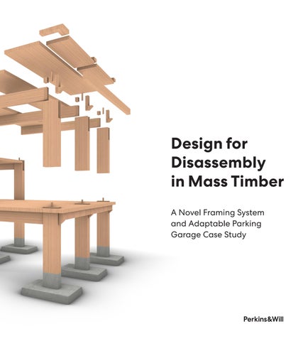
Design for Disassembly in Mass Timber
A Novel Framing System and Adaptable Parking Garage Case Study
V1.5 Released December 2025
Project Team:
Andrew Tsay Jacobs
Anish Reddy
Advisors:
Leigh Christy
Yehia Madkour
Structural Consultant: Eric McDonnell, Holmes Structures
Fire Consultant:
Bevan Jones, Holmes Fire
Parisa Nassiri, Holmes Fire
Timber Framing Feasibility Peer Review: Christopher Evans, TimberLab
Mass Timber Garage Peer Review: Ethan Martin, DCI/Generate
Circularity Peer Review:
Jesce Walz, Perkins&Will

1 De Haro, San Francisco
Photo credit: Perkins&Will
“Design
for Disassembly” (DFD) in its simplest form means designing objects that can be efficiently taken apart without damage to the components. DFD opens the opportunity for components to be reused without entering the waste stream after one use.
The long-term utility of DFD components in buildings is dependent on their durability and their ability to work together in a comprehensive and flexible way through the lifecycles of multiple buildings. Therefore, designing mass timber components for disassembly and reuse requires careful study of a variety of use cases and the development of strategies for preserving wood components for the long term.
For this report, we approached DFD of mass timber within a circular economy context, looking upstream and downstream to understand the supply challenges and economic opportunities inherent in the initiation and repeated deployment of long-lifecycle, interchangeable components that are not unique to a specific project.
Circularity principles and DFD strategies form the basis for decision making in the DFD mass timber context. With these principles and strategies, we developed design criteria for components that can suit a variety of occupancy types including parking, residential, and office. Using a case study approach, we test fitted and refined the components for optimal adaptability, in-situ rearrangement, disassembly, and reuse. This case study approach facilitated iterative refinement of mass timber components, culminating in the Design for Disassembly Mass Timber System (DFD MTS) presented in this report.
The DFD MTS is demonstrated in the appendix through a prototype building that is observed through the lens of its possible future lives. The first use of the prototype is a parking garage, with sloped floors, variable height beams, and a rain-screen envelope. For the second use, the parking garage transforms into an office podium with level decks, reinforcing purlins, enhanced fire protection, interior finishes, MEP, and an exterior curtain wall enclosure. Next, a residential tower is added on top of a central, levelled area of the office podium roof. Finally, the last phase describes disassembly for component reuse in future DFD MTS projects or downstream products.
The final aim of this work is to facilitate a shift in the industry towards imagining building components as reusable assets of a circular economy, with their value decoupled from individual buildings.

Framehouse, Dragør, Denmark
Photo credit: SHL / Perkins&Will
Why Design for Disassembly?
Design for disassembly has been a popular topic in the architecture, engineering, and construction (AEC) industry for decades. However, few commercial-scale buildings have been built using the principles of DFD and fewer have implemented a DFD approach to a mass timber structure. The industry primarily uses material streams, products, and processes that are linear, rather than circular. Circular economies are scarce, and consensus building toward circular economies that benefit multiple stakeholders requires time and planning. Such consensus building also requires establishment of material streams, normalized and predictable components, and processes that allow the end of use of buildings to mark the beginning of the next chapter of their constituent parts as they are disassembled and reused elsewhere.
Design for disassembly is a key element of circular design. Perkins&Will recognizes that a circular economy of construction materials is fundamental to reducing atmospheric carbon and balancing the ecosystem of our planet. The built environment can be seen as a highvalue bank of reusable materials if the constituent materials and components of buildings can be removed in a way that preserves their utility for the next building they constitute. We aim to extend the life of materials well beyond that of the lifespan of a single building by designing with the next use of each reusable component in mind. Without a DFD approach, we risk perpetuating the rapid downcycling, recycling, landfilling, and incineration models of previous centuries and cannot move toward circularity. With a DFD approach, we increase the efficiency of building construction, renovation, adaptation, and deconstruction while eliminating waste.
Why Mass Timber?
Mass timber is generated from trees that pull atmospheric CO2 out of the air and convert it into a carbon-based material useful for construction. By designing the mass timber elements as durable, reusable components that can be disassembled and used in a series of buildings over time without modification, we can understand mass timber buildings as carbon banks, where material assets (the reusable components) are invested and later recovered.

Library, Washington, D.C.
Photo credit: Perkins&Will
Estabilshing an Approach to Mass Timber DFD
The impetus for this research was a client request for a mass timber garage to serve a mass timber residential tower. In addition, Perkins&Will has identified DFD as a key component of sustainable parking garage development, anticipating the long-term reduction in parking needs as a result of autonomous vehicles and an increased variety and availability of other transit modes.
With an end goal of a DFD mass timber garage, we started with a literature review of design for disassembly in the architecture, engineering, and construction context. Through that study, it became clear that at the scale of building component lifetimes, DFD requires a circular economy to repeatedly make use of disassembled parts. Thus, we extended our study into circular design to allow a careful positioning of our DFD for mass timber into a plausible economic context. Finally, we surveyed the literature of existing mass timber garages to understand how this organic structural material can be deployed in such a challenging occupancy.
This review of circularity, DFD, and mass timber garages led us to a pivotal moment. We realized that a one-off garage design that can be disassembled does not meet the highest goals of circularity and DFD principles. Circularity and DFD principles require that any building be resilient, flexible, and reusable—in other words, adaptable to other occupancies. The principles also suggest that the components be reusable without modification in future projects. To develop a system with the required versatility, we took a case study approach, gathering the unique design criteria for parking garage, office, and residential occupancies and seeking common ground within one DFD design. With this broad set of design criteria in mind, we outlined DFD principles that would guide us toward a system of components that are flexible enough in their composition so as to be occupancy agnostic. This system of components— the DFD MTS—is the outcome of the research.
In order to demonstrate the effectiveness of the DFD MTS in a variety of contexts, we deployed the system on a multi-phase adaptive reuse project, illustrated in the Appendix.

Image credit: Perkins&Will
1 De Haro, San Francisco
Literature review of three topics—circularity, design for disassembly, and precedent mass timber parking garages—provides the context and informs the approach for this work.
Circularity
For this report, we referenced existing Perkins&Will research on the topic of circularity, most notably the Circular Design Primer for Interiors. The principles of circularity form the context of DFD, which is itself a mechanism that allows the continued circular use of materials.
Proponents of circular materials and circular economies use a “ladder of Rs” to develop strategies for reducing material use and maximizing product use. The ladder of R strategies evolved over time from the traditional three Rs (Reduce, Reuse, and Recycle) into today’s 10 Rs: Refuse, Rethink, Reduce, Reuse, Repair, Refurbish, Remanufacture, Repurpose, Recycle, Recover (Cramer 1). For this report, we use these 10 Rs to help us identify the parameters that can yield a circular mass timber component system. Later in this report, we develop the specific DFD strategies for mass timber that exist within those parameters to support circular design.
Circular Mass Timber Strategies Through the Lens of the 10 Rs
R0 – Refuse
Before beginning the design process, confirm that the project is indeed necessary and that the functions of the project cannot be accommodated by other means. Once confirmed, approach the design process with a mindset of refusing to use virgin materials when possible (i.e., use salvaged materials).
R1 – Rethink
Rather than following a traditional design-bid-build, owner-operator, demo-and-landfill model, consider an alternate models for materials, contracts, ownership, adaptive reuse, and disassembly for component reuse. For instance, rather than using steel and concrete or virgin mass timber, consider the use of salvaged mass timber. Consider a product-as-a-service model in which the building structure and other primary building elements are actively cared for and maintained by the manufacturers who will reclaim them after disassembly. This model incentivizes the manufacturing, installation, maintenance, and disassembly teams to be synchronized in their goals and methods to ensure the viability of the materials and components for multiple building lifetimes.
R2 – Reduce
Approach the design process with a mindset of overall material efficiency. Minimize the use of raw materials, through design optimization and by preferring reclaimed materials. In addition, use mass timber to achieve multiple performance requirements (acoustic, thermal, structural, fire protection) reducing the need for other materials. Finally, reduce complexity to increase efficiency, flexibility, and resilience.
R3 – Reuse
Mass timber components can be reused, project after project, provided that their connections are designed in a reversible manner and the wood is protected from the degrading effects of water, UV, and insects. Entire buildings can be reused through adaptive modifications, giving them second and third lives before disassembly. In addition, salvaged glulam and Cross Laminated Timber (CLT) decking can be milled to new project specifications.
R4 – Repair
A circular approach promotes active maintenance without wasteful replacement of cosmetically worn items as well as design that passively preserves and protects the materials. Inevitable deterioration of components should be addressed in partnership with a vested manufacturer to restore materials properly, rather than dispose of them. This restoration process is facilitated by the easy removal of DFD components for repair and subsequent reinstallation.
R5 – Refurbish
Adaptive reuse is typically invasive and damaging to primary building elements. In order to preserve the materials and components of a project, the design must allow for alteration and refurbishment without damage to the materials. The components must be able to be disassembled, removed, or rearranged without degradation and must be equipped with plug-and-play connections that accommodate MEP systems, cladding, and fixtures. In addition to refurbishment within an in-use project, individual elements that have been removed from a disassembled project can be refinished prior to reinstallation in a new project.
R6 – Remanufacture
Remanufacture is required when component design must be changed to preserve utility in new applications. Ideally, disassembled components require light refurbishing but no remanufacturing before installation in subsequent component-based projects. However, when remanufacture is required, the least waste will be achieved with components that can be disassembled by non-destructive means.
R7 – Repurpose
Bulky building elements such as glulam beams, columns and CLT decking constitute significant amounts of wood and can be reused as beams, columns and decks for multiple building lifetimes. They can be put to industrial uses such as shoring and tundra pavers. However, they can also be cut down to smaller elements and reused as secondary framing, or smaller scale products such as partition wall frames, furniture, and crates. Other materials of the building core, shell, and interior should be treated in a similar manner over multiple use cycles.
R8 – Recycle
After repurposing wood multiple times in the largest formats possible, it may be reduced to chips that can be pressed into composite panels, such as oriented strand board (OSB). After all possible construction uses have been exhausted, the wood is reduced to wood fiber, which can be recycled multiple times into cardboard and paper products until they are no longer recoverable due to contamination, primarily from oils.
R9 – Recover
Those responsible for disposal of paper products and other upstream, wood-based waste must select the disposal method that does the most good and least harm to the environment. This will typically be measured by weighted values of carbon storage, recoverable energy through combustion, and off-gassing. See Perkins&Will’s Getting to Craft in Mass Timber for more information about the carbon cycle of mass timber.
Design for Disassembly
Groundbreaking work on the concept of Design for Disassembly was developed by Brad Guy and Nicholas Ciarimboli in the mid-2000s. Their work on behalf of the City of Seattle led to the seminal document Design for Disassembly in the Built Environment in 2006 (Guy 1). The work describes the fundamentals of DFD and the shifts in design thinking that are prerequisites for industry change. Key principles of the work include:
• Design now for future reuse without the need for modification
• Provide disassembly and reuse instructions for those who come after
• Design for resilience and to accommodate the unknown future
• Anticipate the future reuse market and develop components to suit that market
• Prove the versatility of components by illustrating a variety of future use cases
• Document and educate all stakeholders on project-specific DFD strategies to ensure follow-through during project development, project life, and disassembly
Subsequently, the design consultancy Bryden Wood pioneered innovative delivery models and concepts that center on component-based design and “platforms” (a.k.a. building scales and types) into which components are deployed. With a focus on Design for Manufacture and Assembly (DfMA), particularly using the UK’s “modern methods of construction” (MMC), Bryden Wood has illustrated systems for material and process standardization to increase quality, reduce design and construction time, and enable more efficient use of natural resources through component-based design.
Their work does not specifically focus on disassembly, but includes the assumption that all aspects of a project are planned for efficient assembly, replacement, or disassembly (Bryden Wood 21). Bryden Wood emphasizes that standardization can add value through optimization and widespread adoption of fewer, better components (Bryden Wood 108). Key to their work is the belief that the entire industry must make constant progress towards standardization, modernization, and automation. From government scale down to small parts manufacturers, Bryden Wood advocates for systemic change and coordinated growth. A similar shift is required for implementation of Design for Disassembly, but of particular relevance is the generation of components that can have a robust marketplace after disassembly.
The construction industry has made small strides towards this type of standardization, with a wide variety of automated systems available for everything from timber partitions (BotBuilt, AUAR, etc.) to steel structural members (ConXtech).
Perkins&Will’s project work and research on prefabrication point toward the value of embedded “intelligence” in components and buildings. (Perkins&Will, Designing 10). Digital components contain analytical information that can facilitate generative design, optimizing functional and material efficiency. Use of DfMA to develop a kit-of-parts catalogue extends the digital process into opportunities for fabrication automation. Efficient design-to-fabrication workflows ensure component regularity across manufacturers and projects, resulting in components that are interchangeable across projects.
Mass Timber Garage Examples
Several mass timber parking garages have been built worldwide. Others have been designed and remain unbuilt. We investigated built and unbuilt garages in Sweden, Switzerland, Germany and the USA (Oregon) and evaluated their approach to mass timber design. None of the designs that we’ve identified had stated DFD ambitions and their resulting construction does not lend itself to other uses or versatile reuse of components.
AIX Arkitekter designed the first mass timber parking garage, completed in 2009 with 141 stalls in Skellefteå, Sweden (Ikhlef 8). The project consists of three floors of parking over one floor of retail, and two subterranean garage levels. A shallow horizontal-louver rain screen provides minimal weather protection, allowing UV, rain and snow to enter the interior. The mass timber elements are exposed, with only a simple polyurethane traffic coating applied to the mass timber floor decks. An analysis by Timber Bridge Specialists performed seven years after project completion was shared by the architect with the authors. The report revealed wood decks in some areas experienced degradation due to ponding water, exposure to rain and snow, condensation on uninsulated pipes, insufficient interior drainage system, weak-points in the traffic coating waterproofing at deck panel joints, and substrate material transitions. Nevertheless, the localized degraded wood was repaired or replaced, and a new polyurea traffic coating (Teknopur 300) was applied with greatly improved performance. Addressing the weak points identified in this case study and using a robust traffic coating are essential features of exposed wood parking garages.


Parking Garage, Skelleftea, Sweden, AIX Arkitekter.
Photo credit: Patrick Degerman
SRG Partnership (now CannonDesign) and KPFF developed an awardwinning design in 2016 of a 360-stall mass timber garage in Springfield, Oregon. The proposal featured advanced engineering concepts, including mass timber rocking shear walls and post-tension cambered glulam girders to achieve sloped decks (Ellowitz 40). Physical testing of various traffic toppings including polyurethane and asphalt was performed at the University of Oregon. Performance of polyurethane and asphalt was demonstrated to be adequate for moisture protection of the wood, with asphalt being selected because it spreads point loads, protecting the softwood decks from local plastic deformation and resultant moistureprotection failure. The design is not intended to be convertible to other occupancies nor are the components of its complicated structural design suited for disassembly and reuse in any other configuration than the garage.

Glenwood CLT Parking Garage
Credit: CannonDesign
Zaugg AG developed a four-floor mass timber car park in Studen, Switzerland (Zaugg 2) with 1200 car stalls. Construction was completed in 2017. Ramping occurs via exterior metal ramp. Columns feature beam pass-through notches located higher at the interior columns and lower at the perimeter columns to achieve 2% beam slope for drainage. Wood connections feature notched wood geometry and minimal use of steel. Two-layer asphalt, 55mm thick, is provided as the traffic topping. The structural components of the system are tailored specifically to the garage geometry and are thus difficult to reuse for future projects. The asphalt topping cannot be disassembled.

Timber-Built Car Park, Zaugg AG
Credit: Zaugg AG Rohrbach
Sege Park, Malmö, Sweden, Lloyd’s Arkitektkontor
Credit: Lloyd’s Arkitektkontor

Sege Park, Malmö, Sweden, Lloyd’s Arkitektkontor
Copyright: Sege Park
Credit: Binderholz

Lloyd’s Arkitektkontor AB designed a six-story, 600-stall garage in Malmö, Sweden, that was completed in 2022 (Binderholz 1). Binderholz provided the glulam columns and CLT floors, composed of their CLT BBS ceiling product. The project focuses on eco-solutions, including bike parking, rain harvesting for façade green walls, and photovoltaic (PV) canopies to charge batteries for EV on-site charging. The project is conceived as a material bank whose vast quantities of mass timber may be reclaimed in the future (Binderholz 1). Relatively standardized sizes and geometry for columns, beams, and decks could theoretically support disassembly and reuse without component modification; however, we found no documentation of a systematic DFD approach to the project. Structural spans are relatively small and corbels in column notches support beams. A variety of driving surfaces are used, including cobbles tone brick paving at ground level, steel grill grating at ramps, and asphalt at parking deck. Prior to application of two 30mm layers of asphalt, a primer was applied to the wood, joint strips were placed, and a bituminous membrane sheet was placed to ensure optimal performance of the traffic surface (PMalmo 1). The perimeter of the project exposes beams and columns to rain and UV; however, hygrothermal modeling was performed to ensure quick drying of timber elements to limit degradation (Strang 1). Column base joints are sealed in upturned flashing and waterproofing. The wood was sealed throughout the project to protect it from moisture, which comes with the risk that if moisture does enter any weak points, it cannot dry out and will lead to rot. In developing the DFD MTS, we strove for a balance between preventing water intake and allowing wood to breathe and dry.
HK Architekten, Hermann Kaufmann + Partner ZT GmbH delivered the B&O Wooden Multi-Storey Car Park in Bad Aibling, Germany, in 2022. The twostory garage features asphalt driving surfaces and wooden rain screens that allow wind-driven rain and snow into the interior (Pintos 1). An exterior concrete ramp brings cars to the second floor. Column bases are raised above the floor surface on concrete pedestals and are fully protected from winddriven rain by solid wood cladding panels. This project and others mentioned deploy asphalt as a flexible and maintainable traffic surface; however, asphalt’s carbon emissions, VOCs, and inability to be disassembled for reuse render it untenable for DFD applications.


B&O Wooden Multi-Storey Car Park, HK Architekten, Hermann Kaufmann + Partner ZT GmbH.
Photo credits: Sebastian Schels

1 De Haro, San Francisco
Photo credit: Perkins&Will
DFD Strategies for Mass Timber
In addition to respecting circularity principles and facilitating circular material economies, DFD must holistically address all aspects of design and construction. The topics below describe a strategic project framework for successful DFD mass timber projects (including core and shell) and serve as the basis of the DFD MTS.
Collaborate
As with any non-traditional and non-linear approach to design, an adaptive- DFD project requires full buy-in from all stakeholders, including operations and maintenance teams. Multi-stakeholder development of a highly detailed digital twin enables clear communication of the physical status, value, and reuse potential of each component.
Communicate
The project manual must contain disassembly and adaptation/alteration instructions. In addition, the manual should identify material streams for components to slip into when disassembled. Existing AEC practice involves tagging mass timber elements with identifying markers to support the construction process. This practice should be enhanced by linking component tags to a wealth of digital information about the components that removes ambiguity and enhances precise communication.
Specifications
The specifications must require the use of salvaged materials and their properties. Specifications must anticipate materials with product-as-aservice agreements, including maintenance strategies. Competitive bid projects should use performance criteria related to percentage of reuse or salvaged material. Reversable connections must be specified.
Agile Schedule
Where possible, salvaged wood should be used for the fabrication of mass timber. However, sourcing reclaimed mass timber in the next few decades will be challenging as CLT is not well represented in existing building stock, and suppliers fabricating CLT directly from salvaged and waste wood are in the early stages of development. Reclaimed glulam is somewhat easier to source, though still challenging. As a result the schedule must allow for sourcing and remanufacturing of salvaged mass timber but may also leverage the schedule savings of predesigned components. If no salvaged wood can be obtained within a generous sourcing schedule, use of virgin materials may be the only way to initiate a mass timber DFD project.
Sourcing
For the foundations, first determine if existing foundations on the site can be reused. If not, consider sourcing reclaimed steel helical piles, driven steel piles, and precast footings. However, for larger structures with challenging soil conditions, piles and precast footings may not be feasible. In this case, a cast-in-place foundation must have a high level of recycled content as well as low-carbon concrete mixes and must be designed for efficient removal or for adaptability to future structures on the site.
MEP systems should be sourced as salvaged (if available) plug-and-playbased systems. While this sourcing effort may be difficult due to current waste-to-landfill material streams, DFD-friendly plug-and-play ducting, wiring, and piping are all available on the new products market.
Cladding should be sourced from salvaged curtain wall panels (including wood curtain walls) that have been refurbished to meet current building code performance requirements. The curtain wall industry is a prefabrication industry. Curtain walls are designed for quick installation and can be quickly disassembled as well. Unfortunately, there is no current market for reused curtain walls due to lack of demand and evolving building code performance requirements that render older curtain walls obsolete. However, reuse of curtain walls is feasible with proper refurbishment. Standardized panel lengths and heights corresponding to the structural grid proposed in the DFD MTS will facilitate a future DFD and reuse market for curtain wall panels. Any future-proof curtain wall panel design will be robust enough to accommodate a range of attachments and armatures, from perforated rain screens to fins, baffles, and lighting fixtures.
While interior materials are not a primary consideration of this study, many of the principles which apply to circular interiors are applicable to
full building projects. For a comprehensive look at sourcing of interior fitout materials for DFD Interiors, see the Perkins&Will Circular Design Primer for Interiors.
Testing, Certification, and Safety
In the near term, projects that deploy a system of DFD components using reclaimed mass timber elements will need to test and certify them to ensure they satisfy performance requirements. Tested and certified materials along with a conservative structural approach that builds in redundancy will ensure that even with long-term wear and repeated reuse of the components, they retain residual capacity for the design loads. Traditional fire protection of wood using noncombustible protection is expensive and adds unneeded materials and construction complexity to DFD projects. A more direct and simple approach of oversizing wood elements to include a char layer achieves better DFD results while maintaining fire safety. The char layer increases component structural capacity in the absence of fire and gives the structure a reliable means of collapse prevention for the design fire duration.
Plan for Next
Over the life of a building, owners and maintenance teams will change. Thus, in addition to project manuals detailing adaptive qualities of the design and disassembly sequences, the building itself must contain the instructions for assembly, alteration, and disassembly. This may be facilitated through physical markings (bar codes, QR codes) and digital tags embedded within the components. In addition, the components must be designed for the next phase or use case of the building life as well as be designed for rearrangement, removal and next-building deployment. Planning for next is planning for resilient transience of components.
Material Banks
Digital models of components and the buildings they inhabit enable precise accounting of the buildings as material banks. The stored value in DFD components can be traded, bought, and sold separately from and in parallel to the real estate and construction markets. The bank of materials can be assembled or disassembled into a number of building configurations over multiple-building lifetimes. On-site storage of materials is a significant challenge on many urban sites, leading to the need for local urban storage facilities that can provide just-in-time DFD components to projects.
Design for Manufacture and Assembly (DfMA)
Mass timber is produced through a digital fabrication process. The automated assembly line that manufactures panels and mills them to millimeter precision has particular constraints and particular freedoms. Understanding these constraints and freedoms allows a DFD mass timber project to be time-efficient on the fabrication floor, quick to assemble onsite, adaptable and flexible in use, and disassembly-ready. For example, the manufacturing constraints of computer numerically controlled (CNC) timber fabrication machines can be fed into the digital design process to optimize the design for minimal material off-cut waste, curved surfaces, durable forms, close-packed stacking for efficient shipping, and self-shoring connections that enable safe and rapid assembly and disassembly.
The shop drawings must also clearly support this intent; otherwise, there is a risk that the very aspects that facilitate DFD are lost in the final fabrication. For this reason, a DFMA approach is essential for DFD.
Design for Adaptation (DfA)
In addition to designing for disassembly, designing for adaptive reuse requires future phases that may require modification or adjustment to the DFD mass timber structure. The design must accommodate many changes, including variations in occupancy load, the addition or modification of
mechanical, plumbing and electrical equipment, the addition or removal of flooring systems, the introduction of partitions, the addition or replacement of curtain walls, and the opening of atriums, light wells or vertical circulation cores. To ensure the viability of future reuse of components, structural connections and anchorage details must accommodate these anticipated changes without compromising the integrity of the components. Accompanying interior designs must be developed to support and leverage the flexibility of the DFD design. Otherwise, the mass timber components may be unwittingly compromised by interior retrofitting.
Design for Longevity (DfL)
Concealed spaces allow unseen deterioration to fester. Allowing the core and shell elements to be seen and allowing the wood to breathe at connections can preserve the life of the wood. All structural connections should allow the steel and wood to breathe so that bulk water cannot be trapped, condensation can evaporate, and capillary action cannot absorb water into wood end-grain. Where bulk water is expected to flow, joint sealing and multicoated protection of joints can prevent entry of the water from above while deck panel joint gaps allow the wood to breathe below. Future use cycles are only possible if the components that are disassembled can be reused without modification or repair. The design of assemblies and connections must avoid proprietary systems that may no longer be in production at the time of disassembly. The joints must be durable and the fastening mechanism removable and repeatable. Details explaining how the elements are connected, adjusted, and disconnected must accompany the design and fabrication drawings.
Digital Twin
The design process will yield a digital twin for the project owner that documents in exacting detail all components of the project at final completion. This digital twin can be updated over time and may be linked to a database of all the components in the project developer’s other projects. Manufacturing stakeholders may develop their own componentspecific digital twin that feeds into a database of their component inventory across all projects. Assessing the maintenance status of the mass timber elements and updating the digital twin with current conditions facilitates a reliable inventory catalogue.
DFD Strategies Summary
The primary design considerations for a DFD mass timber system of components that fits into a circular economy are the following:
• Reduce material use
• Use reclaimed materials and components
• Use renewable and recyclable materials
• Use low-carbon, low-energy-intensity materials
• Use materials that accomplish multiple objectives
• Reduce complexity of assemblies
• Design adaptable and adjustable components
• Design for durability of components
• Design for ease of maintenance of components
• Design a kit of modular components that are nonproprietary
• Design for simplicity of connections with ease of assembly, adjustment, and disassembly
• Design to suit all phases of component lifecycle, starting at the end of life and working back through processes of salvage operations, refurbishment, disassembly, maintenance, adaptive reuse, construction, fabrication, and material sourcing
• Use the DFMA process in partnership with manufacturers, fabricators, and contractors to facilitate seamless design-to-fabrication accuracy, efficiency, and replicability
• Design resilience into components and buildings, including conservative redundancy of critical components
• Design components that support safe manufacturing, transport, and jobsite conditions during assembly and disassembly

RAD Center, University of Houston
Photo credit: Perkins&Will


Case Study Phases: Phase 1 Parking Garage, Phase 2 Office, Phase 3 Residential Tower over Office
Case Study Approach
In the development of the DFD MTS, we adopted a case study approach to evaluate design ideas. We developed simplified design concepts for the components, test-fit them on various building occupancies, found their shortcomings, and revised and refined the design. The parking garage was selected as a starting point for two reasons:
1. Parking garages represent an ideal case for a DFD-focused project, as they are frequently used to fill empty sites near dense areas with incomeproducing property. Parking garages act as a temporary stopgap until the neighborhood densifies and the site can be converted to more intensive uses, requiring removal or repurposing of the garage. Designing garages with future use cases in mind allows the adaptive reuse of the garage structure to become an opportunity to increase value rather than generate demolition waste.
2. With their weather exposure and sloped floors, parking garages present the most challenging environmental and geometric problems for the DFD MTS to solve if it is to maintain adaptability to other uses and component viability for reuse after disassembly.
We test-fitted for office and residential as well as parking garages. We developed the DFD MTS based on the need to satisfy these diverse use cases and building occupancies with one system. As a result, the DFD MTS is physically robust and geometrically flexible.
In the Appendix, the DFD MTS elements derived from the case study approach are deployed through four phases of a single building: Phase
1 Parking Garage, Phase 2 Adaptive Reuse Office, Phase 3 Residential Tower Addition, and Phase 4 Disassembly. Phases 1, 2, and 3 are shown below for reference. See the Appendix for details and full description of the architectural, fire resistance, and structural strategy for each phase.
Below are the occupancy criteria we used to develop the design through the case study approach.
Design Criteria by Occupancy
Parking Garage
• 4 Levels
• Internal car ramps between levels
• 480 Parking Stalls
• 8'-2" minimum headroom on Level 1 (accessible van parking)
• 120 parking stalls per floor
• 23' minimum drive aisles
• 7'-8"x20' compact and 9'x20' full size parking stalls
• Efficient column grid to maximize parking stall count
• 2% sloped floors for water drainage
• Waterproof traffic surface
• Wood joints must allow wood to dry below waterproofing
• 50% open-air rain screen for natural ventilation
• 40psf live load
Office
• 16' minimum clear headroom for Level 1 commercial/retail
• 9'-0" minimum clear headroom for Levels 2-4
• 2-hour fire protection
• Open floor plan (demountable partitions for private office)
• Wood exposed to view
• MEP concealed from view
• Curtain wall facade
• Sound Transmission Class (STC) 50
• Impact Insulation Class (IIC) 50
• 100psf assembly live load (selected areas)
Residential
• 9'-0" minimum clear headroom for all levels
• 2-hour fire protection
• Wood exposed to view
• MEP concealed from view
• Curtain wall facade
• Sound Transmission Class (STC) 55
• Impact Insulation Class (IIC) 55
• 40psf live load
With the combined design criteria of the Parking Garage, Office, and Residential, we used the DFD strategies for mass timber to develop massing, floor level heights, bay sizes, and framing layouts that could satisfy all the criteria. Floor-to-floor heights of 18 feet for the first floor, 13 feet for second and third floors and 15’ for the fourth floor satisfied the height criteria. Internal car ramps between floors resulting in rectangular building massing with ramps running the long direction at 6.5% slope.
7'-8"x20' and 9'x20' parking stalls and 23' drive aisles led to bays of 20'x20', 20'x26', and 26'x26' for efficient stall layout within standard, efficient mass timber deck and beam spans.
Two-hour fire protection combined with the exposed wood requirement led to the use of mass timber sacrificial charring as the preferred fire protection strategy. This was consistent with the DFD strategies of reduced complexity of assemblies and multi-objective materials. A 2-hour-fire equates to 3.2" loss of exposed wood due to charring. Thus, all member sizes were
increased by 3.2" on exposed sides. Connections must also be rated for 2 hours; thus, the structural connections are behind 3.2" of sacrificial wood. We considered concealed steel connectors; however, the DFD strategy of avoiding proprietary elements led us to study wood-to-wood connections that could address vertical and lateral loads.
With bay sizes of 20'x20', 20'x26', and 26'x26', we studied framing options that could reduce the volume of wood and promote efficiency in fabrication, construction, alteration, and deconstruction. There were several apparent incompatibilities that the different occupancies presented, as follows:
1. The parking and residential live load of 40psf was not compatible with the office assembly loads of 100psf. This challenged us to develop a solution that could increase in strength as needed.
2. The sloped floors of the parking garage were not compatible with the level floors of the office and residential occupancies.
3. The floor STC and IIC ratings of the office and residential occupancies were not consistent with the waterproof floor requirements of the garage.
4. The water drainage and piping requirements of the garage were not compatible with the goal of concealing MEP from view in the office and residential occupancies.
5. Adding MEP systems to an existing structure when adapting to office or residential uses presented a concealment challenge.
6. Open-air rain screen of garage is not compatible with curtain wall facade of office and residential.
7. Wood joints of the open-air parking garage must have gaps to allow the wood to breathe to prevent rot from moisture. Gaps are not allowed in 2-hour-rated office and residential occupancies.
The solutions to these challenges that harmonized the multiple design criteria into one system are noted below.
1. Variable strength of the structure
Columns and beams are designed for their ultimate load case of 100psf with an additional 3.2" of char on exposed surfaces. They are therefore extremely robust and durable for service life and multiple cycles of reuse on subsequent projects. Floor decks are the biggest drivers of the quantity of wood fiber in mass timber projects. Therefore, reducing the thickness of the decks is a high priority. To allow the same fiber-efficient decks to support a range of live loads from 40psf to 100psf without thickening the decks, the use of mountable and demountable purlins was devised to assist with deflection, vibration, and flexure, as needed.
2. Variable slope floors
Internal local drains and trench drains were considered to facilitate 2% slopes to drain. A large number of drains or trenches would minimize the rise and fall of the sloped decks to about 6". Conversion to office could leave the decks sloped and use a pedestal raised access floor system to achieve a level floor surface. There were problems with this idea that we couldn’t overcome: (1) Achieving counter-slopes (crickets) is challenging without adding an asphalt topping. (2) Keeping the water internal and flowing over a variety of slopes, valleys, trenches and drain joints increases the potential for ponding water, leaks, and rot. (3) Trench drains at panel joints (above beams) lead to structural connection challenges and irregular panel geometry. (4) Routing of water leaders down from trenches requires notches in beams or decks. Penetrations in decks lead to reduced versatility of the components for use in future projects. (5) Internal drainage pipes increase anchorage requirements/damage on exposed wood surfaces and would require removal in future phases.
We looked for an alternative solution to address these problems. For drainage of the garage, we tried using mono-slopes with a high-point ridge aligned with the core elevators and sloping down to slab edge gutters. This approach reduced all of the risks and problems of the internal drains scheme, but it presented one enormous challenge: the fall distance from the center of the garage to the edge of the garage is approximately 3'-0". This means that the beams at the edges of the garage must be set lower than the center beams, with the intermediate beams ranging between these two heights. We realized that this design problem was the same problem we needed to address at the car ramps where beams are set at various heights to achieve a 6.5% sloped ramp. With two reasons to solve this problem of variable height beams, we set to work on an adjustable, variable-height beam-to-column connection. See the DFD MTS for details.
3. Waterproofing and sound transmission of floors
To keep the wood from getting wet and deteriorating, we needed to waterproof of the decks. Conventional wisdom was to use a sturdy concrete or asphalt topping. Both of these materials present significant disassembly challenges and neither was required for use in office or residential occupancies. In addition, because of normal cracking, concrete would ultimately not protect the wood from water infiltration. Asphalt would require removal and disposal if the occupancy were to change to office or residential. Thus, we needed an alternate: a strong surface to withstand car traffic and a robust waterproof coating to keep the wood dry. Use of hardwood in the top lamination of the CLT decks achieved the strength we needed. Use of a durable traffic coating and well-sealed joints on the top side but open on the bottom protected the wood from moisture damage. This simple assembly allows for occupancy conversion through the introduction of low-profile raised flooring with integrated sound-damping.
4.
Exposed drain pipes
By sloping the decks from the core to the edge of the building, interior drain pipes, penetrations, and anchorage were eliminated. Slab-edge-mounted rain-water leaders at the exterior are demountable when the building is converted to office or residential.
5. Concealed MEP systems
The low-profile raised floor serves the double purpose of sound mitigation and concealment of conduit routing. The mechanical system appropriate for retrofits with minimal exposed equipment is a ductless system with units mounted near the core. Plumbing for office and residential kitchens and bathrooms is to be located in the core, out of sight of the more public spaces.
6. Rain screen and curtain wall systems
The open-air rain-screen of the parking garage is designed to use standard curtain wall anchorage. With a single slab edge anchor detail, the rain screen and the glazed curtain wall become interchangeable. Both systems are conceived as reusable after disassembly from the building.
7. Breathable joints and fire protection of joints
The wood elements of the open-air garage need to breathe and dry out if they become wet. The design uses 1/4" non-combustible, non-compressible shims to maintain gaps between decks. Beam-to-column and deck-tocolumn joints also provide 1/4" gaps. Weep channels are provided in joints where failed waterproofing and resultant trapped water would lead to rot. Sealant and waterproofing is used on the top surfaces of joints to keep water out, but the bottom of the joints is left open for breathability. For the office and residential uses, the bottom of the joint gaps must be closed or filled to prevent fire and smoke from travelling through the joints. For cases where joints can be filled with 1/4" wood strips, color-matched wood strips of 3.2" depth are used to achieve the required fire resistance through charring. Other cases use intumescent strips.
See the description of the Design for Disassembly Mass Timber System (DFD MTS) in this report for more detailed information about the nuances of the system.

Framehouse, Dragør, Denmark
Photo credit: SHL / Perkins&Will

DFD MTS Structural Component Array
Design for Disassembly Mass Timber System (DFD MTS)
Using the DFD strategies outlined above, we developed a family of components for mass timber projects. These components are designed to satisfy the requirements of circular design, adaptive reuse flexibility, and design for disassembly. Together they comprise the Design for Disassembly Mass Timber System (DFD MTS).
We challenged ourselves to create a system that is flexible enough to allow a sloped-floor parking garage to be converted to office and residential uses at scales that require two-hour fire ratings. The DFD MTS’s structural connections, framing layout, member sizes, and anchorage details provide this flexibility.
DFD MTS Composition and Components
Structural Grid
A key characteristic of the DFD MTS is the standardized series of structural grids. The DFD MTS grids are based on efficiency of mass timber materials (reduced volume of material), ease of assembly and disassembly (fewer components), and efficient space plans for a variety of occupancies, including Office, Residential, and Parking Garage. Following circularity principles and our DFD mass timber strategies, we reduced the number of unique components within the system by limiting the bay sizes to three: 20' x20', 20' x26' and 26' x26'. These bay sizes balance material efficiency with space planning requirements for a variety of occupancies.
DFD MTS Foundations
Precast pad footings support the structure (see Figure 1). The footings feature stems matching the size of the column, including rounded corners. Stems extend 1'-0" above the ground floor level. A 5/8" thick steel plate on top of the stems separates the concrete stem from the wood fiber of the glulam columns. A hot-dip-galvanized steel HSS post serves as the alignment post for the ground level columns. Lateral holes through the HSS post allow cabling to run through for crane picking and placing of the footings. Pad width is limited to 8' due to shipping constraints.

FIGURE 1 – PRECAST FOUNDATION PAD COMPONENT

FIGURE 2 – COLUMN COMPONENT
DFD MTS Columns
Columns are designed for long term durability, efficient packing for transport, and simple assembly and disassembly - without proprietary connections.
Standard Column Sizes
Columns cross sections are standardized as follows: 24"x24", 24"x36", 36"x24", and 36"x36" (see Figure 3). Column heights are standardized into 1'-0" nominal length increments for floor-to-floor heights ranging from 10' to 18', to serve a variety of occupancy types.
Column Stacking
Columns are in direct bearing on top of one another. A 4"x4" wooden “key” at the interface between columns aligns the columns and resists lateral forces (see Figure 2). Uplift forces are managed by means of screws extending into the column and through the key, above and below the column-to-column joint (see yellow highlights in Figure 2).
Dovetail Slots
A subtractive manufacturing method is used to create dovetail voids in the column section. These one-size-fits-all dovetail openings extend from the top of the column 4'-0" down and result in “slots” in the column face. These slots allow a variety of other components to be secured to the column, including beams, vertical spacers (see yellow highlight in Figure 2), and corbels. These swappable components are slotted into the top of the column during assembly and can be removed vertically out of the top of the column during disassembly.

FIGURE 3 – COLUMN TYPES
The dovetail shape locks components in place laterally while eliminating the need for proprietary connections and reducing the need for steel in the connections. Note that vertical spacers do not feature the dovetail flanges as they are intended to be horizontally removable from the face of the column for beam and corbel height adjustment. Once spacers are removed laterally, the beam height can be adjusted by means of jacks and new spacers inserted below the beam at the revised height. Face screws secure the spacers to the column.
Because the column design for the garage accommodates beams in one direction, it only has two dovetail slots. However, 2-hour columns with three or four dovetail slots are proposed as part of a larger DFD mass timber system library of components.

FIGURE 4 – COLUMN 2-HOUR CHAR LAYER
Durability
The column section has no protruding features that can be easily damaged. Column edges are rounded with a 2.5" radius to reduce splintering and damage to the columns in transport, assembly, occupancy, and disassembly.
Fire-Protective Design
Columns are oversized with a 3.2" char layer on all sides to resist 2-hour fires without structural compromise (see Figure 4). The dovetail connections are recessed 3.9" beyond the face of columns to protect the critical bearing connection.


FIGURE 5A and 5B – COLUMN BASE PROTECTION PLATE AND CORNER GUARDS
Weep Channel
The column dovetail features a ½" weep channel running vertically down the back face of the dovetail slot and running horizontally along the base of the dovetail slot to the face of the column. If water seeps into the column joint, this weep channel allows it to escape. For projects that are fully enclosed and have no risk of bulk water infiltration, the horizontal portion of the channel is to be filled with a square dowel.
Column Base Protection Plates
The bases of columns are surrounded by formed and fabricated 10-gauge steel bent plates screwed to the CLT decks (see Figure 5A). The plates are aligned with the slab edges surrounding the columns, maintaining a ¼" gap for breathability. The L-shaped plates extend 3" onto the deck and 7" vertically from the CLT decks. These collars protect the column joint from bulk water infiltration and serve as a baseboard to protect against incidental damage to the column base.
Column Corner Guards
For impact areas, such as loading/receiving and parking, 10-gauge steel corner guards with rubber backing protect the glulam columns (see Figure 5B). Corner guards are anchored to the base protection plates rather than directly to the columns with fasteners or adhesives.
Disassembly
Disassembly of columns requires removal of all overburden including columns above, decks, and dovetail slot components (beams, spaces, corbels), as well as unscrewing of uplift screws and crane picking.
General Notes
1. Mass timber fabrication tolerances are within 1/16”. Joints in mass timber are typically 1/4" for ease of assembly and to allow the wood to breathe. 1/8” joints are possible and do not require fire protection; however, the DFD MTS prioritizes ease of assembly and disassembly as well as breathability for long life of the wood and uses 1/4" joints.
2. Cross-laminated timber is dimensionally stable. Glulam has very low longitudinal expansion but significant width and depth expansion when its moisture content changes. The use of 1/4" joints allows the large beams and columns of the DFD MTS to swell and contract as changes in ambient relative humidity impact the internal moisture content of the glulam. Further analysis of swelling of dovetail joints is required for validation of the DFD MTS design in climates with wide relative humidity swings.
3. Detailed fabrication simulations of the dovetail slots can ensure precise and optimal geometry for the broadest range of CNC milling equipment.
4. Spacers and corbels are relatively small and difficult to process in the same fabrication sequence as beams and columns. Fabricating longer lengths that are cut down to individual spacers or corbels may ease this difficulty. However, fabricators of all elements must carefully coordinate to ensure consistency of species, grade, grain orientation, and tolerances.
5. In jurisdictions requiring ductile steel connections between wood members, the use of one or more screws through the face of columns and secured to embedded beam ends in the dovetail joint may be required to satisfy authorities having jurisdiction (AHJs). However, performance-based design may be used to overcome such requirements.
6. Use of dovetail connections requires full-scale structural and fire testing.

6A and 6B – BEAM ASSEMBLY INTO COLUMNS

FIGURES
DFD MTS Primary Beams
The DFD mass timber system beams are designed for material efficiency, durability, and simplicity of assembly and disassembly.
Standard Beam Sizes
The DFD MTS uses a standard width of 14.25" for beams. Beam depths vary from 18" to 30" in 3" increments. Beam lengths from column face to column face vary from 17'-24' in 6" increments.
Column Slot Spacers
A column slot spacer below the beam sets the bottom of beam at the required height (see Figure 6A). The column slot spacer above the beam secures it against uplift (see Figure 6B).
Fire Protective Design
Beam widths and depths include a 2-hour, 3.2" char layer on the bottom and sides. Dovetail connection to columns is deeply embedded in the columns behind the conservative 3.9" char line to ensure bearing connection integrity in a 2-hour fire (see Figure 6).
Disassembly
Disassembly of beams is accomplished by unscrewing and removal of decks, unscrewing and removal of dovetail slot spacers, and crane picking of the beams.
DFD MTS Perimeter Beams
Slab edges are supported in one of two ways:
1. In the primary deck-span direction, decks cantilever over columncentered beams to the slab edge (see Figure 7A). Filler decks on the outboard face of the columns span between the cantilevered deck edges and are secured with 45-degree screws (see Figure 7B).
2. In the transverse direction, corbels in the column slot support perimeter beams (see Figure 8).


FIGURE 7A and 7B – SLAB EDGE ASSEMBLY
The corbels provide vertical load support for the perimeter beam while face screws in anchor the beam to the column slot spacers. Perimeter beams and interior decks support slab edge decks (see Figures 9 and 10). Note that the inside edge of slab edge decks requires shoring until diagonal screws are placed. The perimeter beam and corbel are sized for 2-hour char.
Disassembly
Disassembly of perimeter beams follows the removal of the decks. Perimeter beams supported by corbels are unscrewed from column slot spacer and picked by crane. Column slot spacers and corbels are then unscrewed and removed out the top of the columns.


FIGURE 10 – SLABS SUPPORTED BY EDGE BEAMS
FIGURE 9 – EDGE BEAM SUPPORTED BY CORBEL
FIGURE 8 – CORBEL IN COLUMN SLOT
DFD MTS Purlins
Glulam purlins fixed with top-down screws through the deck are used to stiffen the decks (see instances of screws highlighted yellow in Figure 11). The purlins are not attached to adjacent beams as they are merely stiffeners and do not transfer vertical loads at their ends.
7-Ply double-span CLT Decks with 20' spans do not require stiffening purlins except in areas with 100psf live loads, such as office assembly areas. The purlins can be added to existing buildings if occupancy or live loads change. Removal of deck deflection by means of jacks is required prior to purlin installation.
7-Ply double-span CLT Decks with 26' spans require stiffening to meet flexure, vibration, and deflection criteria for 40psf to 100psf live loads of garages, residential, and office. Thus, 26' spans will always feature purlins.
Standard Purlin Sizes
Purlins are 10.75" wide by 15" deep with lengths of 17' for 20' bays and 23' for 26' bays.
Disassembly
Disassembly of the purlins is achieved by unscrewing from above.

FIGURE 11 – PURLINS SECURED TO DECKS WITH SCREWS (HIGHLIGHTED YELLOW) TO RESIST DEFLECTION

FIGURE 12 – DECKS SYSTEM ARRAYED ON POST AND BEAM FRAMING
DFD MTS Floor Decks
It is possible to use Glued Laminated Timber (GLT), Nail Laminated Timber (NLT), or Dowel Laminated Timber (DLT) for the decking of a DFD mass timber building. However, several criteria led to the selection of CLT for the DFD MTS decks:
• CLT can accommodate incidental two-way spanning scenarios such as those inherent in the “filler decks” (see below).
• CLT is more impervious to water and smoke infiltration than NLT and DLT, which is critical in certain occupancies, such as open-air garages.
• CLT is dimensionally stable, which lends itself to the application of sealers and traffic coatings such as Polyurethane Methacrylate (PUMA) that are designed for dimensionally stable surfaces, including wood substrates.
Double-span decks
Efficient deck design is the most direct way to reduce the volume of wood in mass timber projects. We use double-span decks to reduce the deflection and allow for 7-ply panels to span 26' bays. To achieve double-span decks, we ensure that decks run past columns uninterrupted and without cut-outs (see Figure 12). This maximizes the reusability and repositioning potential of the decks in future phases and future buildings because they remain simple “blanks.” Floor decks are secured to beams by means of top-down screws (see Figure 13) and are secured to one another with diagonal screws to achieve diaphragm continuity and deflection uniformity.
Standard Deck Sizes
Deck width is determined by bay size and column size. By limiting the column sizes and bay sizes in the DFD MTS, we reduce the number of unique deck widths to six: 9'-0", 8'-9", 8'-6", 8'-0", 7'-10", 7'-8". Standard lengths are multiples of 20' and 26' bays, yielding 40', 46', and 52' lengths.
Filler Decks
Because double-span decks sidestep the columns, there is a floor gap to fill between columns. This gap is addressed with “filler decks” secured directly to the adjacent flanking decks by means of diagonal screws. The filler decks combined with the double-span main decks enable cheap and rapid fabrication because decks don’t require complex CNC processing, which is typically the bottleneck and fabrication schedule driver.
Durable Deck Composition
Durability of the decks for multiple building lifetimes is a top priority of the DFD MTS. Protecting from impact damage, scrapes, moisture, UV, and overall wear and tear are all critical to the long-term utility of the decks.
• The top layer of the CLT laminations is hardwood and all other layers below are softwood. The use of hardwood as the top layer gives the decking the durability needed for multiple building lifetimes of use. Softwood lacks the perpendicular-to-grain strength to resist local deformations expected for some occupancies, such as parking garages. Such deformations can lead to premature failure of waterproofing and traffic coatings, making softwood not suitable as a top layer unless load-dispersing overburdens are applied (Haynes, 10). Such overburdens (typically poured concrete or fluid-applied asphalt) constitute an unnecessary deadload and either can’t be disassembled or are not suitable for conversion to other occupancies due to high VOC content.
• Decks are factory finished on all sides with penetrating stain that prevents bulk water intake while allowing the wood to breathe and release internal moisture. Expected moisture content must be evaluated for each climate to ensure moisture content of decks does not exceed 20% and lead to delamination failure.
Deck Joints
Deck joints are ¼". Noncompressible, noncombustible shims at 2'-0" on center are used to maintain the gap and allow the deck end-grain to breathe. Decks are connected to beams by vertical screws placed behind the 3.2" char line. Decks are connected to one another by top-down screws, set at an angle and with spacing corresponding to diaphragm forces and differential deflection mitigation. For occupancies featuring Type IV-B or IV-C construction, the bottom of the joint is filled with an intumescent strip that will swell to fill the gap in the event of a fire. The intumescent strip is secured with screws to allow for easy removal and reuse of the intumescent strip.

FIGURE 13 – DECK TO BEAM CONNECTION
Fire Protective Design
The thickness of the 7-ply CLT decks anticipates 3.2" of wood char providing two hours of fire protection without compromising the strength of the decks (see Figure 14). Deck deflections after a fire event exceed occupied deflection limits, but the residual 6.43" CLT thickness is structurally adequate to prevent collapse after a 2-hour fire.
Disassembly
Decks are disassembled by unscrewing them from adjacent decks and picking them with a crane. Perimeter decks are removed first (after cladding has been removed). Infill strip decks are then shored and unscrewed from adjacent panels before being picked by crane. Finally, double-span decks are unscrewed from beams and from one another and picked by crane.


FIGURE 14 – CHAR REDUCTION OF BEAM AND DECK
DFD MTS Screws and Dowels
Connections featuring screws between mass timber structural elements must ensure that no portion of a screw is within the 3.2" char layer of the structural elements. Thus, screw heads in the sides or bottom of structural elements are to be driven 3.2" into the face of the wood, leaving a hole in the face of the structural elements. This hole is to be filled with flush wood dowels lightly tapped into place. The wood dowels can be removed by drilling a slightly smaller hole through them, inserting a screw and then pulling out the dowels, exposing the screw head underneath.
Top-down screws into CLT decks are permitted to be flush with the wood as the char layer is on the underside of the wood.
Lateral Braces
Building codes in the United States do not allow braced frames to be composed of mass timber without a performance based design approach. There are current proposals to change that; however, we have adopted steel buckling restrained braced frames (BRBFs) for the DFD MTS until wood braced frames are permitted.
Steel beams are used in lieu of glulam beams at braced frame locations. The steel beams are fireproofed and connect to the columns in a relatively conventional manner with knife plates and bolts. Steel elements of the lateral system are to be hot-dip galvanized to ensure the long life and future reusability of the lateral system components.
Note: Further integration of steel braced frames with the mass timber DFD MTS components is a topic of future study. Integration should reduce or eliminate the bolts and plates that require milling and drilling of holes in the columns.
Stairs
Stairs and stair shafts are to be composed of precast concrete to simplify construction and deconstruction while providing fire resistance. Connections between stairs and mass timber framing are limited to lateral connections between stair shaft walls and mass timber decks by means of hot-dip galvanized steel ledgers mounted to the outside of the stair walls.
Enclosure
Modular and reusable curtain walls or rainscreen systems are to form the perimeter walls of the DFD MTS. These should be sourced from circular economy suppliers who avoid sealants, relying instead on long-life gaskets that can be easily replaced and recycled without component disassembly. The anchorage for the curtain walls shall be slab-edge mounted galvanized-steel-plated assemblies secured to the top surface of the CLT by means of slab edge anchors. For occupancies requiring fire separation between floors, slab edge firestopping shall be provided to seal the gap between the CLT deck edge and the inside of the curtain wall. Curtain wall anchor fasteners shall be behind the 3.2" char depth on the slab edge to ensure the integrity of the anchorage during a 2-hour fire event.
Photovoltaics
Photovoltaic systems may be integrated into the rainscreen, curtain wall, or roof of the project. These systems must feature replaceable components to ensure long-term viability and serviceability. Roof-mounted PVs shall use ballast to avoid penetrating the roofing membrane and putting the wood structure at risk of moisture infiltration.
Precast Floor Panels
Mass timber is not suitable for on-grade walking or driving surfaces due to soil, moisture, and insects. Thus, ground level floors are composed of ongrade precast deck panels secured to each other with mechanical anchors.
Roofing
Roofing materials are to be long-lasting and reusable. Sheet membranes are to be composed of fully recyclable materials.
• 2 1/2" precast planks
• ½" reusable drainage mat
• Recyclable modified bitumen sheet membrane waterproofing
• 5/8" Plywood sheathing
• 2" wood-fiber insulation panels to thickness required by energy code
• Vapor barrier sheet membrane for CLT deck protection
Flooring and Traffic Coating
The built-up flooring system designed for the DFD MTS can be disassembled, is nontoxic, and has no negative impact on the reusability of the mass timber components. The composition is as follows:
• 1/2" Magnetic tile assembly (carpet, tile, or other finish)
• 1/4" Acoustic mat
• Two layers of 1/2" thick structural concrete panels
• 2" Acoustic pads inside steel track surrounded by batt insulation with concealed conduit
The floor assembly provides impact sound transmission (IIC) of 56 and air-borne sound transmission (STC) of 58, suitable for a wide variety of occupancies.
The two layers of structural concrete panels achieve the 1" thickness non-combustible overburden required by IBC 2024 for type IV-A, and IV-B buildings.
Conduit and cable are routed through the insulated cavities flanking the 2" steel track, reducing ceiling-mounted conduit runs. Flush-mounted data and power outlets are provided in the finished floor surface.
For open-air occupancies such as parking garages, polyurethane methacrylate (PUMA) traffic coating is applied directly to the CLT. PUMA is a hard-wearing, zero-VOC traffic coating suitable for dimensionally stable materials, such as CLT, while allowing for occupancy conversion without removal. It can be maintained and resurfaced and should be left in place as permanent protection of the decking if the project is converted to another occupancy and even after disassembly. PUMA is a multilayer system consisting of a primer, base coat, wear coat, and topcoat. Joints are protected with a flexible sealant (such as Tremco’s Dymonic 100) and a backer rod in the joint. In addition, joints receive an additional stipe coat of PUMA.
PUMA will require monitoring and maintenance to ensure the protection of the wood components. Weak points noted over the life of the project may be reinforced with self-adhesive flashing, or light-gauge metal flashing set in multiple layers of PUMA. These approaches are last-resort options because flashings complicate disassembly and may lead to more challenging refurbishment.
Notes
1. Other traffic coatings may be acceptable if they exhibit the following properties: nonflammable, slip-resistant, high mechanical strength and elasticity, adhesion to wood, waterproof, chemical stability, chemical resistance, UV stability, zero VOCs, abrasive wear durability, easily cleaned, and allowing recoating. Preference should be given to recyclable coatings and those made of recycled materials.
2. The International Building Code Section 406.2.4 requires parking garage floor surfaces to be “concrete or similar approved noncombustible and nonabsorbent materials.” The use of PUMA over mass timber will require justification to the AHJ and will likely involve fire testing of PUMA on mass timber surfaces. Alternatively, an overburden on top of the PUMA consisting of a ½" drainage mat and 3" thick reinforced precast panels with dimensions 72"x24" may be used to satisfy code requirements. This option allows infiltrating water to drain and allows for disassembly without destructive demolition.
Mechanical, Electrical, Plumbing and Fire Sprinklers
All MEPFS systems should be selected from suppliers that have clear documentation of product integration in the circular economy. System routing should minimize the need for anchorage to wood. Bolt-in-bolt anchors are preferred because during disassembly the lead anchor bolt can be left in the wood and the anchor position reused in future projects. Anchors to deck should be centered or symmetrical within structural bays. Electrical systems and wiring for lighting, signage, power, data, and A/V should anticipate the needs of future phases and allow for expansion and branching without duplication of conduit lines. Conduit routing occurs in the acoustic layers of the flooring to avoid unsightly ceiling routing, unnecessary anchorage to the long-life CLT decks, and floor deck coring/ penetrations.
Fire sprinkler system is a prerequisite in all DFD MTS projects. The long-term value of the components is such that preservation of them is of highest priority. Sprinkler systems should be anchored to the bottom of CLT decks and should not penetrate beams or decks.
Future phase mechanical systems can be mounted and demounted using removable screws fastened to the deck. Ductless split systems are preferred because they feature removable modular components, minimize material by eliminating ducts, and offer flexible efficiency by serving local areas only instead of entire floors or the entire building. First phase plans and the digital twin model should suggest optimal mechanical layout with minimal anchorage to the DFD mass timber. The DFD MTS features options for oneway beam framing, with beams running from the core to the perimeter. This allows routing of conduit (and ducts when used) to exit the core tight to the deck for a cleaner look and maximum headroom.
Future phase plumbing systems are located away from the mass timber framing and decks. This ensures that leaks are not detrimental to the wood components and eliminates the need for penetrations through the mass timber systems. Bathrooms and kitchens are to be located in the core areas of the building on precast decking, rather than on perimeter areas with mass timber decking.
The stormwater collection system is fed by sloped roof decks (and sloped floors in the case of parking garages) that lead water to the edge of the building where it is collected in gutters leading to rainwater leaders. To preserve the life of the wood, monodirectional slopes to gutters are critical. Monodirectional slopes provide a continuous unobstructed path to water drainage while avoiding the weak points at drain penetrations and the shallower slopes of valleys. The gutters and downspouts should be sourced based on circular economy principles and installed with reversible fittings and anchorage.
Note: Garages typically use the top deck of the structure for parking. However, in the case of the DFD MTS, a ramp leading to the top deck would expose the interior of the building to rainfall and runoff from the ramp, significantly increasing the risk of water damage to the wood elements; therefore, a garage top deck serves as a protective roof, and is not accessible by vehicles.
Partitions
Future-phase partitions may consist of demountable modular systems, or be purpose built and designed for disassembly. In either case, reused sources of partition materials should be prioritized.
Partitions should be sourced from circular economy suppliers who avoid sealants and adhesives. Partitions must avoid anchorage to the beams and deck above and therefore require self-contained lateral bracing. Partitions should also support localized ceiling systems. If anchorage to decks above is unavoidable, UV/shade staining will result on the deck and beams. To reduce this adverse effect, UV-permeable glass and minimal contact area with the wood should be prioritized.
Ceilings
No ceilings are required for the DFD MTS. The exposed wood structure is the interior finish. Acoustic attenuation is achieved without the use of ceilings (see Flooring and Acoustic Panel descriptions).
Acoustic Panels
Future-phase acoustic panels should prioritize circular sourcing and their quantity should be limited to those areas where measured acoustic conditions dictate their necessity. Application to the face of beams using sturdy tracks with as few screws as possible should be given priority as such applications can be carefully and uniformly applied. Application to the underside of deck is discouraged as it will lead to a scattered field of anchor points that is aesthetically undesirable and will lead to UV/shade staining patterns on the wood surface.

Library, Washington, D.C.
Photo credit: Perkins&Will
Conclusion
Design for Disassembly requires a holistic approach to that considers the source, adaptability, and lifespan of each building component, independent from the life of a building. Starting from the conceptual framework of a circular economy and leveraging the potential of modern CNC fabrication techniques for mass timber, we arrived at the Design for Disassembly Mass Timber System of components that can compose a variety of building types and scales.
Relevance
Construction technologies come and go. Individual companies also come and go. The development of a system of components that can be disassembled and reassembled centuries into the future requires consideration of timeless non-proprietary construction technologies and assemblies. The DFD MTS is a system of components that may be fabricated by many manufacturers to allow a stock of interchangeable components to be built up over time. As fabrication and construction technologies evolve and engineered materials continue to improve, improvements and alternate systems will emerge.
The economic model described in this report centers around leasing of building materials. This model does not yet exist but may be advantageous in future DFD-driven markets. In the near term, the disassembly of a building will require disassembly by salvage companies who purchase the components from the building owner. The salvage company may not have the same insight on reuse or refurbishment of varied construction materials that a manufacturer/leasing company of specific components would have, but they can nevertheless sell the materials and allow them to re-enter the built environment.
Results and Findings
The DFD MTS features one-directional post-and-beam glulam framing with CLT decking and a 2-hour char layer on all members. The key to the system is an adjustable beam to column dovetail connection that allows identical columns to accommodate a wide range of connecting elements. DFD MTS buildings are geometrically constrained by the components of the system. Similar to many other preplanned, prefabricated systems, rectilinear massing or a composition of smaller "boxes" that are composed into a larger whole is expected. This orthogonality reflects the typical forms of the existing built environment, but it is a limitation that does not admit curves, cantilevers, long-span systems, or other specialized structural compositions. When developing the system to have flexibility to accommodate multiple occupancy types, we accepted compromises and some constraints on each occupancy.
The DFD MTS reduces the use of screws compared to traditional mass timber construction by means of a dovetail joint between beams and columns. Most of the connections of the DFD MTS eliminate screws from the primary structural load path and limit their use to secondary loads, such as uplift forces and lateral forces, which reduces their quantity and size, leading to less overall damage to the wood through multiple assembly and disassembly cycles. In addition, the DFD MTS conceals most of the screws. Screw removal is a challenge we did not address in this study. Deck screws in a garage will be covered by the traffic coating, making removal difficult. In addition, screws in columns and beams must be recessed 3.2” into the wood and the hole plugged for fire protection. Removal of the plugs and screws in this scenario is a challenge.
The DFD MTS uses post and beam framing and a central structural core with shafts and vertical circulation. These features are typical in the industry, however the bay sizes selected are somewhat unique to the system as they are primarily based on parking layout requirements and maximum economical sizes for standard-manufacture mass timber elements. It is possible to design for longer spans that are more suitable to office occupancies while still work for parking; however, such spans require trusses, post-tensioning, or other non-standard geometries that are less “off-theshelf” products and introduce complications for disassembly and reuse; thus, the bay sizes developed are the best fit for the selected occupancies.
Further Study and Next Steps
This report does not explore test fit options for offices and residential. Future studies of interior fit-outs as well as other occupancies will reinform the decisions from the present study and improve the utility of the DFD MTS. Each improvement that can be made to the DFD MTS and each of its limitations is a reminder that it is just one of many systems that can be developed by an industry moving toward circularity and design for disassembly.
Many of the assumptions of this report require further evaluation and testing to determine their validity. The structural connections require iterative prototyping to evolve into the most efficient forms for manufacturing processes. In addition, the connections require structural testing to confirm performance. The garage floor assembly requires physical testing to confirm that deck deflections, traffic wear, and moisture will not lead to early compromise of the traffic coating or joint sealants. Full integration of the lateral force resisting system into the DFD MTS requires further consideration and study. Mechanical, electrical, and pluming systems and routing also require careful study for their successful integration into floor assemblies and exposed structural ceilings.
As circularity principles gain traction in the AEC industry, development of DFD strategies and assemblies will allow an increase in the lifespan of materials and building components, thereby reducing dependency on virgin materials. This research points to a future that can begin now—a future in which the built environment is not a landscape of buildings destined for demolition, but rather an arrangement of components in building form that can be taken apart and used again and again in new configurations.

Orchard Commons, University of British Columbia
Photo credit: Perkins&Will
References
Binderholz, Sege Park Multi-Storey Car Park, https://www.binderholz.com/ en-us/mass-timber-solutions/sege-park-multi-storey-car-park-malmosweden/ (accessed 12/31/2024
Bryden Wood, Delivery Platforms for Government Assets: Creating a marketplace for manufactured spaces, UK, 2017, https://www.brydenwood. co.uk/filedownload.php?a=9969-5d78cbf52e90d
Cramer, J., The Raw Materials Transition in the Amsterdam Metropolitan Area: Added Value for the Economy, Well-Being and the Environment, Environment, 2017, 14-21, https://doi.org/10.1080/00139157.2017.1301167
Ellowitz, J., Wesse, P., Sustainable Parking Garages in Wood, The Parking Professional, 2018, 40-41. https://issuu.com/theparkingprofessional/docs/ tpp_2018_12_issuu__1_
Guy, B., Ciarimboli, N., Design for Disassembly in the built environment: a guide to closed-loop design and building, City of Seattle, 2006, https:// lifecyclebuilding.org/docs/DfDseattle.pdf
Haynes, M., Coleri, E., Estagi, M., Selection of the Most Effective Pavement Surfacing Strategy for the Glenwood Cross Laminated Timber Parking Garage, Construction and Building Materials, 2019, 10, https://doi. org/10.1016/j.conbuildmat.2019.07.220
Ikhlef, Y., Parking 2+3 étages en bois massif Skellefteå, Suède, 8th Forum International Bois Construction FBC, France, 2018, https://www.forumboisconstruction.com/conferences/92_FBC2018_Ikhlef.pdf
Perkins&Will, Designing for Volumetric Modular—A Framework for Product and System Evaluation, Vancouver, Canada, 2024, 10
Designing for Volumetric Modular—A Framework for Product and System Evaluation by Perkins&Will - Issuu
Perkins&Will, Getting to Craft in Mass Timber, USA, 2023, 10-23, https:// issuu.com/perkinswill/docs/getting_to_craft_in_mass_timber_design_v3-0
Perkins&Will, Circular Design Primer for Interiors, USA 2024, https:// perkinswill.com/circular-design-primer-interiors/
Pintos, P., B&O Wooden Car Park, ArchDaily, 2023, https://www.archdaily. com/992146/b-and-o-wooden-car-park-hk-architekten-hermannkaufmann-plus-partner-zt
PMalmo, Concrete asphalt is laid in the car park in Sege Park, 2021, https://www.pmalmo.se/Om-parkering-Malmo/mediarum/aktuellanyheter/gjutasfalt_i_P-huset/ (accessed 12/31/2024)
Strang, M., European Case-studies for Multi-storey Mass Timber for Moisture-safety and Energy Efficiency, Joseph William Gottstein Memorial Trust Fund, Melbourne, 2024, 240911091828_240428_Strang_ GottsteinFundReport.pdf
Zaugg, M., Dawn of a New Era – World First Timber-Built Car Park, 8th Forum International Bois Construction FBC, France, 2018, https://www. forum-boisconstruction.com/conferences/91_FBC2018_Zaugg.pdf

Case Study: DFD MTS Garage, Office Podium, Residential Tower, and Disassembly

Case Study Phase 3 - Residential Tower on Office Podium
To explore the feasibility of the Design for Disassembly Mass Timber system (DFD MTS) system, a case study project is described in this Appendix. The prototype is a multiphase building project including a parking garage that is adapted to an office, then a residential tower addition, and is finally disassembled.
The parking garage represents Phase 1 of the case study. The use of the DFD MTS facilitates a Phase 2 conversion of the garage to office space through rearrangement of the components and inclusion of additional components. Phase 3 uses the DFD MTS components to add a seven-floor residential tower to the top of the Phase 2 office space. Phase 4 describes the disassembly of the components for reuse in subsequent projects.
Parking garages are perhaps the most difficult occupancy for the DFD MTS. The traffic surface wear, moisture, and floor drainage are difficult to address while adhering to a disassembly and reuse mandate. The first criterium to address is sloped floor surface for drainage. Flat mass timber decks with a tapered, removable precast concrete topping could meet the slope criteria, but cracks in the concrete will lead to moisture trapped below the concrete, leading to rotting wood decks. In addition, tapered concrete topping slabs have very little reuse potential. Another strategy is sloped asphalt topping. However, asphalt cannot be disassembled, it can only be demolished, and the use of carbon-intensive asphalt runs counter to the purpose of selecting carbon-sequestering mass timber as the framing system. Lacking a suitable topping system for achieving slopes, the decision to slope the mass timber decks and use a robust traffic coating leads us to ask, how can the DFD MTS accommodate sloped decks, and how can they be leveled for use as office space or residential, and ultimately disassembled and reused on future projects? In addition, how does the DFD MTS accommodate the specific moisture and fire resistance, finish requirements, utilities, and structural loading of such diverse uses? This case study demonstrates the application of the DFD MTS in this challenging context and addresses these questions.

Figure P1.1 – Phase 1 Garage Typical Floor Plan
Phase 1: Parking Garage
Occupancy Type: Garage, Group S-2
Construction Type: IV-HT
Number of Floors: 4 (6 allowed for IV-HT S-2 occupancy)
Height: 59' (18' for first floor, 13' for second and third, 15’ for fourth)
Building Area: 199,200 sq ft (346,500 sq ft allowed)
Fire Rating: Unrated superstructure required for HT (2 Hour Provided)
Sprinklers: Yes
Ventilation: Natural ventilation (50% open perimeter walls)
Phase 1 Architecture Description
The garage features a rectangular floor plan and four stories of parking (see Figures P1.1-3, 6). Upper floors feature up to 114 parking spaces, 86 fullsize car spaces sized 20'x9' and 30 compact car spaces sized 20'x7'-8". Van parking and ADA parking is located on the ground floor with additional ADA parking available at each level near the elevators. Two stairs at the ends of the core run from ground to roof. Stair shafts are enclosed with precast wall panels for enhanced fire protection and disassembly ease. A bank of three elevators is located at the center of the building with space reserved for three more when future adaptive reuse necessitates. The one-way beam framing runs in the short direction across the building. Vertical offsets of successive beams allows decks to be sloped between beams. Car ramps with 6.5% slope one side of the core interconnect the floors. The floor on the other three sides is sloped to gutters at the short edge of the building with a highpoint ridge at the elevator bay. Note that dovetail joints between beams do not allow sloped beams; therefore, drainage to the long edge of the building is not possible. A rain screen curtain wall surrounding each floor prevents wind driven rain at up to 60 degrees from vertical from entering the structure while remaining 50% open to natural ventilation, eliminating the need for mechanical ventilation (see Figures P1.4-6, 8, 9). The roof is not accessible by vehicles and the PUMA system is protected from UV by precast panel pavers (see Figures P1.3, 6, 7, 8, 10). Ballast-supported photovoltaic panels are arrayed on the precast paving.


FIGURE P1.2 – PHASE 1 TRANSVERSE SECTION
FIGURE P1.3 – PHASE 1 LONGITUDINAL SECTION
Parking bays 20' long and drive aisles 23' wide lend themselves to a materially efficient grid for glulam framing and CLT decking. Using a composition of the standard DFD MTS bay sizes—20'x20', 20'x26' and 26'x26'—achieves a compact and functional garage layout that is also reprogrammable for office and residential occupancies.
Precast flooring of the ground level extends up the ramp to 8'-0" above the ground floor level to provide a run-off area for wet vehicles before they reach CLT decks (see Figure P1.9). In addition, wind driven rain is significantly mitigated by the rain screen façade. Nevertheless, ponding water must be managed to avoid damage to the DFD MTS components. Accounting for deck deflections, a 2% overall slope to the decks will yield at least a 1% slope everywhere in the garage, allowing ponding water to be eliminated. Thus, decks are sloped at 2% (1/4" per 1'-0") from a center high-point toward gutters at the short edges of the building. The deck slope is achieved using level beams set at different heights relative to one another. Beams set at different heights requires activation of the versatility of the DFD MTS beam-to-column connection design. A 2% slope from center to edge results in a fall distance of roughly 3'-0". Setting beams at this low positions requires the dovetail slots of the column to be taller than those of the standard DFD MTS system (see Figure P1.11). However, no future utility of the column is lost through this adaptation because the column slot “spacers” that allow the beams to be set at varied heights can be replaced with those lengths needed for future phases and projects.
We require all sloped decks of Phase 1 to be reusable as flat decks of future phases, so we determine a length that works for all phases. All decks are sized for 1/4" gaps in the flat deck configuration of the standard DFD MTS.
However, with 2% slope, double-span 40' decks must cover a distance 3/32" longer than flat decks. By using the flat deck standard length and simply raising to 2% slope we obtain only slightly larger 11/32" (1/4" + 3/32") gaps in the sloped decks of Phase 1. These gaps occur atop supporting beams to which deck ends are screwed. Noncompressible, noncombustible shims are to be used to fill the 11/32" gaps prior to sealant and traffic coating applications.
The garage ramps are sloped at 6.5%. For this more extreme case, we anticipate 1 1/4" gaps in the 6.5% sloped decks of Phase 1. Again, shims are to be used to fill the gaps prior to sealant and traffic coating application.
Car Barrier Beams
At the perimeter of the building, glulam car barrier beams are used in the Phase 1 garage (see Figure P1.4). The top of the barriers is required by code to be 2'-9" above the deck and the bottom must be no more than 18" above the deck. The car barrier must accommodate an impact point load of 6,000 lbs. A fall-protection guard is mounted to the top of the perimeter beams.
On the long edge of the building, the 2'-9" tall barrier beams are vertically supported on the outside of the columns using wood corbels slotted into the column dovetail connection. Lateral support for the beams comes from built-up steel components screwed into a dovetail-locked spacer. The barrier beams serve double-duty as upturned beams carrying the “filler decks” that run between columns.

FIGURE P1.4 – PHASE 1 CAR BARRIER BEAM TO SLAB CONNECTION
On the short edges of the building, water running off the 2% sloped deck must be allowed to run under the barrier beams. Therefore the barrier beams are raised up off the deck and are supported using built-up steel seats screwed into column slot spacers.
Car barriers are not needed for occupancies other than garage occupancy and may be removed or relocated for future phases. For Phase 2 Office occupancy, we propose that the car barrier beams on the short edge of the building (see Figure P1.5) be removed from the project by unscrewing them and their steel anchors. On the long edge of the building, the upturned car barrier beam can be relocated under the deck and vertically supported on a lowered corbel. This allows the occupant view in the Phase 2 Office to extend to the floor while making use of the existing on-site component.

FIGURE P1.5 – PHASE 1 SLAB EDGE AND DRAINAGE AT SHORT EDGE OF BUILDING

FIGURE P1.6 – PHASE 1 AXONOMETRIC
The components of the DFD MTS garage and the sequence of work are outlined below.
Phase 1 DFD MTS Components
• Precast footings with upstand pedestal and steel peg for glulam column alignment
• Precast floor decks for first floor on grade and extending up the first floor ramp to a height of 8' above first floor slab
• Buckling restrained braced frames with steel beams
• Factory-sealed glulam beams and columns fabricated from reclaimed glulam if possible. Manufacturer/fabricator to provide product-asa-service maintenance support for all wood members on lease to the building owner.
• Factory-sealed CLT decks (from reuse sources, if possible) with the field application of PUMA traffic coating on the top surface. Source PUMA from manufacturer providing a 0 VOC product, such as Tremco.
• Car barrier glulam beams
• Elevators
• Precast stairs with supporting precast walls
• Sprinkler System
• Electrical systems for interior lighting, lighted signs, emergency systems, A/V, vacant parking stall locators, EV charging
• Roofing: 2.5" precast planks, drainage mat, sheet membrane, 5/8" plywood sheathing, 2" wood-fiber insulation panels, vapor membrane
• Slab-edge anchors
• Rainscreen curtain panels with horizontal louvers capable of preventing 60-degree angle wind-driven rain
• Column base protection plates
• Column corner guards
• Gutters, flashing, and rainwater leaders
Alternative approaches to ownership and maintenance of products are emerging and are an important part of the circular economy. Explore the potential to lease components or engage in product-as-a-service contracts that facilitate maintenance to ensure that elements are in the best condition possible throughout their life cycles. While these models are more common for interior materials, they may be available for equipment or even structural components in the future. Such models have the capacity to benefit the building owner, tenants, and leasing company who will reclaim the materials when the building is disassembled.
Phase 1 Sequence of Work
• Site Prep and Excavation Groundwork
• Place precast footings
• Place precast Level 1 floor decks
• Install Level 1 columns on precast footing pedestal and alignment post. Secure with metal-penetrating screws to prevent uplift.
• Install column dovetail slot spacers of prescribed heights to
• achieve varied beam mounting heights for the sloped floor of Level 2.
• Erect buckling restrained braced frames
• Install Level 2 beams at dovetail connection with column. Add spacers above beams and secure with screws to prevent beam uplift.
• Install Level 2 floor decks, double-spanning over beams.
• Screw decks to beams from top-side down. Add differential deflection screws at an angle to connect decks to each other and reinforce lateral diaphragm.
• Install column base protection plates, screwed down to decks.
• Add deck-to-deck sealant and backer rod at 1/4" joints.
• Apply PUMA traffic coating to decks, including an additional stripe of PUMA traffic coating at panel joints and at column base protection plates.
• Install column-to-column guide peg and Level 2 columns. Add upliftpreventing screws.
• Install column dovetail slot spacers of prescribed heights to achieve varied beam mounting heights of Level 3.
• Repeat beam, deck and column installation sequence for remaining levels.
• Install slab edge anchors
• Install slab edge gutters, flashing and rainwater leaders
• Install rain screen curtain panels
• Install roofing materials on roof deck

FIGURE P1.7 – PHASE 1 GARAGE ROOF PLAN


FIGURE P1.8 – PHASE 1 ROOFING PARAPET
FIGURE P1.9 – PHASE 1 GROUND LEVEL PERIMETER AND FOUNDATION


FIGURE P1.10 – PHASE 1 ROOF DETAIL – SECITON
FIGURE P1.11 – PHASE 1 FLOOR TO BEAM CONNECTION – SECTION


FIGURE P1.12 – PHASE 1 CHAR AT BEAM TO COLUMN CONNECTION – PLAN
FIGURE P1.13 – PHASE 1 CHAR AT DECK TO BEAM CONNECTION - SECTION
Phase 1 Fire Protection Description
Type IV-HT structures are composed of large wooden elements that are assumed to have sufficient fire resistance for the size of buildings allowed for this construction type. However, the DFD MTS structural elements feature conservative 2-hour sacrificial char layers on decks, beams, and columns. In addition, fire sprinklers are provided and stair shafts are protected with precast enclosures. The Phase 1 garage is Group S-2 occupancy.
Floor decks are 7-ply, 9" thick CLT panels. A 3.2" loss to the underside of a panel will result in 5.8" remaining panel thickness. Glulam beams are 14.25" wide. 3.2" loss on each side results in 7.85" width (see Figure P1.13). Columns are 24"x36". 3.2" loss on all sides results in 17.6"x29.6" columns. See structural description for strength analysis.
For glulam, 2 hours of charring results in 3.2" loss to all exposed surfaces. At vertical load-bearing connections, the code requires the bearing area to be reduced by an effective char depth of 3.9" for added safety. Connection design of deck to beam requires that the bearing connection be concealed behind 3.9" of sacrificial char. Thus, on a 14.25" wide beam, there will be 6.45" bearing area shared between two decks. With a ¼" gap between decks, there is just over 3" bearing depth remaining per deck. Fasteners should be located within this 3" deck-edge bearing zone.
Connection design of beam to column requires that the bearing connection be concealed behind 3.9" of sacrificial char. Thus, the dovetail design begins 3.9" from the face of the column and extends inward to a bearing depth 4.1" deeper, resulting in a pre-fire bearing depth of 8" (see Figure P1.12). See structural for bearing area analysis.
Column to column bearing connection must anticipate 3.9" loss on all sides. 24"x36" columns will be reduced to 16.2"x28.2" with additional cutouts at dovetails. See structural for bearing area analysis.


FIGURE P1.14 – PHASE 1 BEAM AND COLUMN BEARING AREAS
Phase 1 Structural Description
Column Design. Using the standard connection designs of the DFD MTS, we selected column sizes for the case study project based on two primary load cases: 1) Future phase maximum enhanced load, and 2) 2-hour fire load case. We assumed the future phase Office load case includes 100psf live load for assembly spaces. We also assumed the future phase seven story Residential tower will be imposed on the podium structure; thus, columns and foundations are sized for the ultimate load case. The 2-hour fire load case reduces column cross sections by 3.2" on four sides.
We determined the minimum cross-sectional area of the column required by structural loads and identify 24"x36" columns as the DFD MTS component most suitable for all phases and adaptive reuse cases of the project. The 24"x36" columns have adequate cross section at the dovetail beam interface to accommodate office loads and residential tower overburden. In addition, the residual cross section after a 2-hour fire is adequate to support the column axial loads in the fire load case.
The dovetail connection design is checked against the maximum anticipated loads for office assembly occupancy and after a 2-hour fire. For the 26' span beams the bearing area required for occupancy loads is 84.5 in2. The DFD MTS provides bearing area of 99 in2. The fire load case requires a bearing area of 50.4 in2. The DFD MTS provides 54 in2. behind the 3.9" bearing connection char line (see Figure P1.14).
Beam Design
Beam width of the DFD MTS system is set to 14.25". We determined beam depth through analysis of the largest tributary areas of the deck and the longest beam spans for the phase with the highest dead and live loads. The office and residential phase dead loads exceed that of the parking garage phase because of the added flooring and MEP system. In addition, the office phase live load is the highest. The widest tributary area is (20'+26' / 2) = 23' and the longest span is 26'. Thus, we designed the beams for office dead and live load with tributary area of 23' and span of 26'. The corresponding beam size from the DFD MTS system is 14.25" x 30". We set all beams equal to this size to maximize the reuse potential of all-matching beams in the disassembly phase.
Deck Design
The office and residential phases of the project are Type IV-B construction, and the DFD MTS uses 7-ply as the standard component in this case. 7-ply panels are adequate for flexure, deflection and vibration in the Phase 1 garage for 20' spans. However, 26' spans the panels are governed by flexure, deflection, and vibration and require the addition of purlins anchored to the decks.
Lateral Design
The deck diaphragms are achieved using the DFD MTS method of deck-todeck screws at 45-degree angle as well as deck to beam screws. Screw spacing will depend on seismic zone, ranging from 3" to 12" on-center for both deck-todeck screws and deck-to-beam screws.
Steel buckling restrained braced frames resist the lateral loads of the project at the building core and at the four corners of the garage. Because these are diagonal braces, careful coordination of headroom at passageways is required. The design of the BRB system itself is outside of the scope of this report.

FIGURE P2.1 – PHASE 2 OFFICE FLOOR PLAN
Phase 2: Adaptive Reuse Office
Occupancy Type: Office, Group B
Construction Type: IV-B with 2 Hour Char Layer
Live Load: 100psf (assume office must accommodate assembly loads)
Number of Floors: 4
Height: 59'
Fire Rating: 2 Hour (provided by 3.2" char layer in accordance with IBC 602.4.2)
Sprinklers: Yes (Required)
Ventilation: Mechanical
Phase 2 Architecture Description
Phase 2 converts the garage into office space. The ground level 18' high floor is converted to retail on one side of the building. The other side of the first floor is reserved for back of house services and parking. Upper floors are converted to office.
The rain screen of the garage is replaced by a curtain wall that uses the same slab edge anchorage (see Figure P2.6). A variety of curtain walls may be used in accordance with location-specific climate requirements.
The zero-VOC PUMA traffic coating is left in place and covered by low-profile acoustic flooring (see figure P2.5, 6).

FIGURE P2.2 – PHASE 2 AXONOMETRIC
The components of the office adaptive reuse and the sequence of work are outlined below.
Phase 2 DFD MTS Components
• Factory-sealed glulam purlins
• Column slot spacers to support beams at raised heights
• CLT decking to infill removed stair cores
• Mechanical system and anchors (ducts, air handlers, diffusers, registers)
• Glazed curtain wall (with slab edge mineral wool)
• Flooring
• ½" magnetic carpet tile flooring over magnetic substrate
• ¼" acoustic mat
• Two layers of ½" thick concrete panels
• 2" acoustic pads inside steel track surrounded by batt insulation and concealed conduit
• Prefabricated self-supporting interior partitions (integral ceilings)
• 1" Wood-fiber acoustic panels (if sound attenuation is required)
Phase 2 Sequence of Work
• Remove rain screen, leaving slab edge anchors in place
• Remove perimeter flashing and gutters on Levels 2-4 and return to leasing company.
• Unscrew column base protection plates and store on site
• Working two bays at a time, unscrew and raise decks using forklifts. Store decks in adjacent bays on the same floor OR raise them up in place and support with shoring on floor decks below.
• Using jacks on floor below, raise beams to level-office floor height
• Replace decks and anchor to raised, leveled beams. Continue with subsequent decks and beams.
• Reinstall column base protection plates
• In areas of office atrium, remove decks, return to leasing company
• Stiffen floor decks in assembly areas by attaching purlins
• Working on half of the first floor at a time, remove precast slabs on grade and store stacked on the other side of the interior first floor.
• Add and compact soil to level the first floor and replace the precast floor decks. Repeat for the other half of the first floor.
• Add flooring finishes (see Figure P2.7).
• Install curtain wall on Levels 2 - Roof (with slab-edge mineral wool)
• Add ductless mechanical system
• Add flooring with integral electrical wiring
• Add self-supporting interior partitions (with integral ceilings)
• Add acoustic treatment to beam faces


FIGURE P2.4 – PHASE 2 LONGITUDINAL SECTION
FIGURE P2.3 – PHASE 2 TRANSVERSE SECTION

FIGURE P2.5 – PHASE 2 DECKS RAISED TO CORE LEVEL HEIGHT – SECTION


FIGURE P2.6 – PHASE 2 DECKS RAISED AND CURTAIN WALL INSTALLED
FIGURE P2.7 – PHASE 2 LEVELED GROUND FLOOR AT PERIMETER

FIGURE P2.8 – PHASE 2 ATRIUM FRAMING WITH REMOVED BEAM, DECKS, AND FILLER DECKS
Phase 2 Fire Protection Description
Conversion to office includes upgrading the open-air garage from Type IV-HT construction to Type IV-B. This improves the fire performance of the structure including slab-edge fire-safing, non-combustible flooring protection, and intumescent strips at structural joints.
Phase 1 was designed to the requirements of Type IV-HT with the anticipation of Type IV-B in future phases; however, Phase 1 does not include a 1" or thicker noncombustible covering on the floor decks. It was not included because parking garage performance criteria do not necessitate the concrete topping, which traps moisture below, leading to decay of the wood in the weather-exposed environment of the open-air garage. However, Phase 2 curtain wall cladding protects the interior from weather and the 1" noncombustible covering requirement is met with two layers of ½" concrete panels in the floor assembly. The construction type is changed to Type IV-B, allowing greater building area, number of floors, and height for business occupancies than allowed by IV-HT.
Phase 1 included purlins on 26' deck spans. Phase 2 requires the addition of purlins to 20' deck spans in assembly areas of the office to accommodate the live load. DFD MTS purlins of 10.25" width will be reduced to 3.85" thickness in a 2-hour fire. This is not a problem, however, because 26' span decks and 20' span decks have sufficient flexural capacity to support structural loads in a fire event without purlins.
Atriums are a frequent feature introduced in adaptive reuse projects to accommodate inter-connecting stairs or visual access between floors shared by one tenant. Atrium opening(s) in the office floor require fluid dynamic analysis to evaluate all fire risks (see Figure P2.8). analysis is beyond the scope of this study. However, down-standing baffles at atrium edges can be used to contain hazardous fumes and smoke in a fire event. These baffles are anchored to the underside of decks and faces of beams using stiff steel channels that reduce the number of screw anchor points into the wood.
Phase 2 Structural Description
The office block includes areas with assembly live load of 100psf. In these areas, the 20' span decks of Phase 1 are governed by flexure and deflection and require the addition of purlins to the bottom of the decks. The decks are shored during installation of the purlins to remove dead load deflection. DFD MTS purlins with 10.25" width and 15" depth are then secured to the flat CLT decks with top-down screws through the decks before shoring is removed.
The Phase 1 decks are sloped for drainage purposes. Raising and leveling the floor decks to the elevator landing level of each floor requires raising the beams that are set at various heights on the columns. First, column slot spacers above the beams are removed by unscrewing and horizontal removal. Then, jacks supported on the floor below raise each beam (and the decks supported by it) to level the decks. To avoid overstressing the screws that secure the decks to the beams, raise beams sequentially, 3" at a time, before returning to the first beam and repeating the process. When all beams have been raised to the appropriate height, relocate the dovetail spacers below the beams and secure with the setting screws. Jacks can then be lowered so that the beams rest on the spacers.
Note: The beams and decks of the Phase 1 garage are sized for the Phase 2 dead load plus 100psf live load and have sufficient strength to support the dead load of two floors when no live loads are present. Jack point loads must be distributed to avoid crushing the CLT decks on the floor below.
Leveling the decks by raising the beams result in changes in braced frame length. This can be mitigated by replacing the entire brace or by replacing the gusset plates.
Open the atriums by removing the screws securing decks to each other and to beams. Raise the decks using lifts. Remove decks horizontally out the side of the building (after rainscreen curtain has been removed and prior to glazed curtain wall installation). Lateral forces of the floor diaphragms are redistributed around atriums and can be accommodated by the remaining framing and floor decks without modification.

FIGURE P3.1 – PHASE 3 RESIDENTIAL TOWER TERRACE LEVEL PLAN
Phase 3: Residential Tower over Office Podium
Occupancy Type: Office (Levels 1-4), Group B; Residential (Levels 5-11), Group R-2.
Construction Type: IV-B with 2 Hour Char Layer
Number of Floors: 11
Height: 150' (59' + 7 floors at 13' each)
Fire Rating: 2 Hour
Sprinklers: Yes
Ventilation: Mechanical
Phase 3 Architecture Description
Phase 3 adds a seven-floor residential tower over the Phase 2 office podium (see Figures P3.1-4). The footprint of the residential tower is set back from the podium by one structural bay on all sides. The terrace areas outside the tower footprint a covered with precast pavers and feature partition screens to create private outdoor spaces for the residents of the lower level of the tower. The roof decks and beams within the tower footprint are leveled up to the core level finished floor height (see Figure P3.6).
Perimeter decks on the short edge of the building slope to existing gutters. Perimeter decks on the long edge of the building are set 6” lower than the tower footprint decks and feature tapered insulation with waterproofing to drain water to new gutters. Parking on the ground level is maintained for residential parking and three dedicated elevators are added to the core to serve the residential tower.

FIGURE P3.2 – PHASE 3 AXONOMETRIC – RESIDENTIAL TOWER OVER OFFICE PODIUM
Tower slab edges feature the same curtain wall anchorage detailing as Phase 2 (see Figure P3.5)
Interior partitions, finishes, and MEP systems are deployed in a manner similar to the Office Phase. Plumbing and mechanical are to be located in core areas. Electrical is run in the floor and in the partition walls with a preference for no overhead conduit.
Note: Other residential tower configurations are possible but not developed in this study. An L-shaped tower would allow a large garden deck on the podium roof. Alternately, two residential towers each served by two stairs and two elevators could be designed. The office podium could also be reduced in height and converted to two stories of retail and parking allowing for more floors of residential. Inset balconies for each of the residential units are also possible provided that they utilize a sloped finished surface that can be disassembled.
The components of the adaptive reuse and the sequence of work are outlined below.
Phase 3 DFD MTS Components
• See Phases 1 and 2 for core, shell and interior components to use in Phase 3 tower construction.
• Tapered insulation and waterproofing
• Gutters
• Fire partitions separating residential units
Phase 3 Sequence of Work
• Raise sloped roof decks to create level tower decks
• Add tapered insulation and waterproofing to perimeter decks and cover with existing precast pavers
• Add gutters to the long edges of the roof
• Install balasted exterior partition walls to divide outdoor spaces
• Add Levels 5-11 on reduced footprint (perimeter bays become garden terrace) using the same structural, utilities, and finish materials from Phases 1 and 2, with the addition of firewall partitions.


FIGURE P2.4 – PHASE 2 LONGITUDINAL SECTION
FIGURE P2.3 – PHASE 2 TRANSVERSE SECTION


FIGURE P3.5 – PHASE 3 TYPICAL SLAB EDGE DETAIL AT RESIDENTIAL TOWER FLOORS
FIGURE P3.6 – PHASE 3 ROOF TERRACE TRANSITION TO BASE OF RESIDENTIAL TOWER
Phase 3 Fire Protection Description
The tower fire protection strategy follows the same strategy as the lower floors but with mixed-use occupancy, again of Type IV-B construction. Careful study of total floor area is needed for each jurisdiction to confirm whether 3-hour vertical separation is required within the building. Phase 3 massing is below the area threshold that triggers separation requirements in most jurisdictions, but it is slightly above the threshold in California. Projects in California would need fewer floors or smaller footprint of the tower, podium, or both to avoid vertical separation requirements in California. Residential units must be fire-separated. This is achieved by means of 1-hour fire-rated prefabricated partition panels extending from deck to deck. These are installed prior to flooring installation.
Phase 3 Structural Description
The residential tower design uses the same structural, core, shell, and interiors components as the office design. The residential tower live loads are less than the office live loads, which results in lower utilization of their strength capacity. In addition, the deflection of the 26' span decks does not require purlin reinforcement as deflection is kept within allowable limits for the residential live load.
Wind loads and seismic loads are managed by braced frames at the core built on top of the braced frames of Phase 1. The additional loads imposed on the podium columns and lateral system were anticipated in the Phase 1 design and require no revision to the podium structure.
Raising the podium roof deck to level the floors follows the same procedure as implemented in Phase 2 leveling of garage floors to adapt to office use.
Phase 4: Disassembly
Phase 4 Architecture Description
When no further adaptive reuse can add value on the site, the building should be disassembled into its constituent components. The components may then be redeployed in future builidngs.
Phase 4 Sequence of Work
• Interior finishes, partitions, and furniture to be dismounted and returned to leasing companies
• MEP components to be disassembled and returned to leasing companies or enter salvage/recycle streams
• Curtain wall to be dismounted and returned to leasing company
• Mass timber components to be disconnected by means of unscrewing. See the description of the components of the DFD MTS for disassembly process for each element. Elements remain stable after unscrewing and are ready to be lifted out by boom or tower crane. Suspended purlins to be removed in laydown area. Mass timber decks, purlins, beams, and columns to be returned to leasing company. Screws to be evaluated for reusability and/or recycling.
• Buckling restrained braced frames to be removed and returned to leasing company
• First floor precast slab planks to be removed, cleaned, and returned to leasing company
• Foundation footing overburden to be removed and footings to be cleaned and returned to leasing company
Appendix End Note
This illustrated deployment of the DFD MTS for parking garage, office, and residential occupancies highlights the versatility of the system. Further case studies exploring a variety of site constraints and additional occupancies can help to refine and validate the system.
• Note: In lieu of leasing companies reclaiming their components, the building owner can engage a salvage company to disassemble the building components for future deployment in the built environment.
Phase 4 Fire Protection Description: N/A
Phase 4 Structural Description
The structure should be disassembled in the reverse order of assembly to ensure structural stability. The majority of structural elements are designed to be stable even when screws are removed from the primary wood elements. Vertical structural loads are transferred by means of bearing surfaces. Thus, removal of screws from primary wood elements does not pose a risk of collapse. The screws are provided to limit differential deflection of decks and to secure elements against uplift and lateral (seismic or wind) loads. Thus, during demolition, removal of screw fasteners can proceed quickly and after screws are removed, cranes can quickly remove elements. This approach is different from disassembly of steel beams, for example, which typically require continuous crane-picking support during disassembly so that elements do not fall when fasteners are removed. The approach is also different from reinforced concrete construction, which cannot be disassembled.
Floor decks utilizing purlins should be removed by crane prior to removal of purlins to increase disassembly efficiency. Purlins can be unscrewed from the decks in a laydown area or off-site. Infill decks between primary decks are supported by adjacent decks by means of diagonal screws and without bearing surfaces. These infill decks should be supported from below or by crane prior to removal of screws.