Architectural Engineering
Portfolio
Heesoo Yang


University of Waterloo - Enclosure
Design Studio
Duration: 6 weeks
Software Used


The purpose of this project was to reclad the Environment 1 building in the University of Waterloo. eplace the existing exterior cladding system with a new high-performance system, in order to improve the building’s energy efficiency, reduce its carbon footprint, enhance its aesthetic appeal, and ensure compliance with current building codes and standards.
The image below is a modelled using Rhinoceros and redenered using v-ray. It shows how the recladded Environment 1 will look like based on our plan.


The wall is composed of Polyisocyanurate to keep the R-value high and have with high rate of recyclability of material. It is connected through ISO clips with thermal isolater to avoid thermal break.

3D rendered image of Recladded Environment 1 (South Side)
Overall look of how recladded image would look like when it’s renovated

The reclad was focused on south section of the building as highligted in site plan and was built in the following panel design that can be seen in elevation.

The edge between first floor and basement details were displayed out for clarity along with parapet details. A lot of the details were referenced from the building science resources.


The shading device used for our project implements BIPV panel to reduce the energy usage of cooling and heating loads of the building and is incorporated as part of the wall, which required us to figure out how exactly it will be manufactured. The triple glazed window filled with Argon is used to have maximum efficient R-value of the wall.
This rendering image, made throuhg Rhinoceros display how the daylighting of the building would look like before the reclad from the inside.

The set time for both image was June at Waterloo. From the image, it is evident that the occupant will receive a better diffusive lighting through a new window and shading device.

Axonometrical Structual 3D Model
(9m x 18m x9m)
Skeleton of the building consists of footings, foundation walls, columns, beams, trusses (Wide Flange Beams used for structural members)

University of Waterloo - Enclosure
Design Studio
Duration: 4 weeks

Software Used
Different wall cladding used for each unique walls: wood veneers for south facing wall, concrete panel for west and east facin wall, and Standing seam panel for roof and north facing wall.
 Axonometrical Rendered 3D Model (9m x 18m x 9m)
Overhead doors and 20% window to wall ratio in south facing wall for the maximum exposure to sunlight. One type of cladding overlapping each corners for the continuous insulation and membranes. Window placed high on south side wall to incorporate natural air flow between south wide window and north side window. High windows on south side operable through extended crank handle.

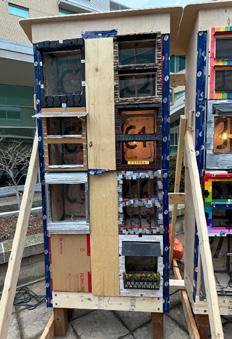
The intent of the SuperShed Project is to explorate intrinsic combination of structure and envelopes of various types.

Shed with building dimension of 9m by 18m was designed mainly using REVIT 2023.
Through this project, I developed an understanding of the make-up of a range of wall and roof enclosure systems, and the challenges in detailing enclosure systems.
The main idea of this shed was to incorporate 3 different types of cladding (wood venner, concrete panel, standing seam steel) and enclosure systems that accounts for the execution of the consturction and the overall energy performance of the shed.
4 “ XPS foam insulaion connected to plywood sheathing with Cascadia Clip. Roof wrapped around the trusses to ensure continuos membrane and insulation. Cotinuous flashing used at the ends to avoid mositure accumulation.

Continous membrane and insulation by wrapping arorund the trusses, same cascadia clip to attatch insulation. Spray foam coated at the web of the trusses to avoid thermal bridges.


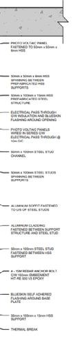
Skeleton of the facade consists of the flexiglass, insulation, modelling baord, stone tiles, and shading device

University of Waterloo - Enclosure
Design Studio
Duration: 2 weeks
Software Used


The Façade Design Lab is intended to be a small-scale field experiment to explore the connection between thermal dynamics and building enclosure design. The objective of facade was to design an aesthetical façade that is pleasing for the onlookers outside of the apartment complex, to ensure thermal comfort for the occupants residing inside the complex, to maximize the energy efficiency of the façade by not requiring prolonged heating.
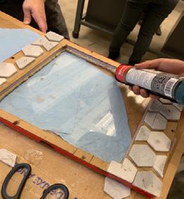
The façade is made up of three different layouts covering its entirety. The top and bottom portions consist of porcelain tiles arranged in intricate layouts
A single shading device on a square window makes up the 70% window-to-wall ratio layout. The tiles are arranged in a calculated manner and it is ensured that each tile portion has a minimum of 1 mm gap in the middle to facilitate expansion and shrinkage of the tiles due to the weather.

The cladding system comprises porcelain tiles on top of a wooden chipboard. All sides of this cladding are protected by water-resistant duct taping, which ensures no damage to the inside or outside edges of the façade. Furthermore, as a method of rain-screening and cheap protection, the façade is coated with waterproofed black spray paint that unifies the aesthetic.
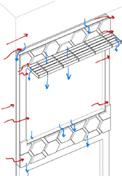
The wind loads, displayed as red arrows occur along the sides of the façade and the shading device. The sturdiness of the façade and its cuboidal dimensions, it allows wind loads to pass over on top and exit. The same goes for the wind loads applied to the shading device, allowing the wind to pass on top and below its surfaces.
The snow loads, displayed as blue arrows ido not pose much of an issue to the shading device due to the lattice having wide enough gaps to let much of the snow pass through without allowing it to settle. As for the window-to-wall connections inside the façade, we provided a duct-tape-based flashing that extends onto the tiles below and allows any accumulated snow and water to flow down without damaging the layers of the façade.