patrick onyia
design portfolio
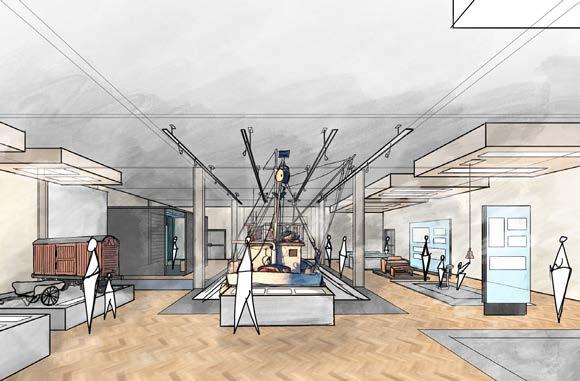
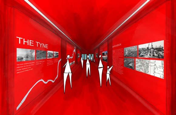
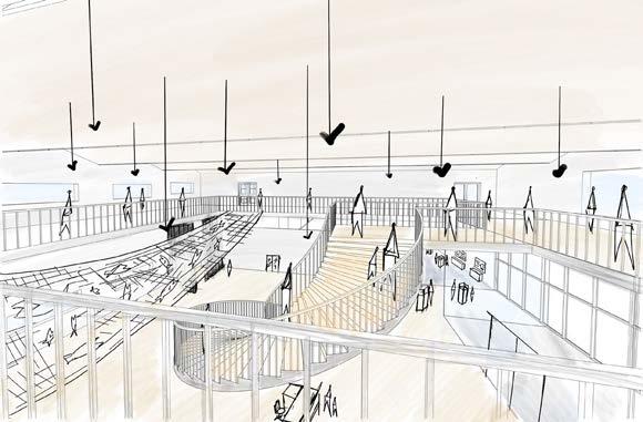
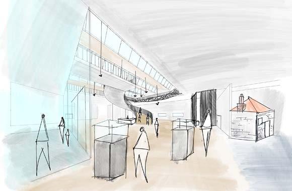
table of contents Introduction Sheels Park and Visitor Centre 1 peri-urban place-making The Motherland Project 2 urban place-making Museum of Extinct Species 3 sustainable ecological enclave Architectural Technology and Design 4 year abroad - VIA University College, Denmark Urban/Regional Planning and Design 5 year abroad - Florida Atlantic University, USA
SHEELS PARK AND VISITOR CENTRE
Sheels Park and Visitor Centre aims to be a local ecological landmark which utilizes the landscape to enhance the lives of wildlife by the Tyne as well as human values. One of the primary goals of the project is to provide a sustainable source of employment for the local residents of North Shields. Additionally, the park and visitor centre through the means of exhibits and specially curated spaces aims to educate visitors not only on the ecology of the Tyne but also on the rich history of North Shields and ship repair yards like Smith’s Dock - the project site. Mediums of wildlife conservation such as Kittiwake towers, an Urban Meadow and Swift Bricks have been implemented to cater to the needs of the local wildlife by the Tyne.
Taking advantage of the large brownfield site, Sheels Park hosts a range of recreational spaces for the local community, building upon the disconnected public space by organising new spaces that leverage previous site footprints.
Strategic programming:
• Rain gardens and tree clusters provide intimate spaces within the vast site.
• The Playground, a hard landscape area comprising of a football pitch, basketball court, tennis court, and children’s play area, promotes social interactions and the creation of connections.
• A multi-purpose lawn comprising of a range of tree cluster densities can be used by the public for community events and activities.
• The entire park is accessible and welcomes visitors with disabilities.
Site Information
Site: Former Smith’s Dock site
Address: Ballast Hill Rd, North Shields, UK NE29 6BZ
Area footprint: 102,507m2
1 Sheels Park and Visitor Centre
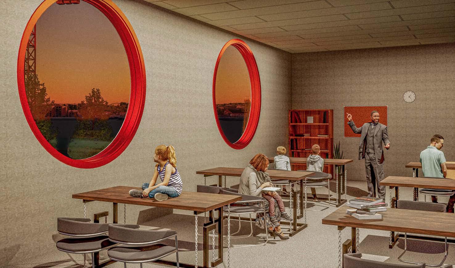
Key Space: Classroom
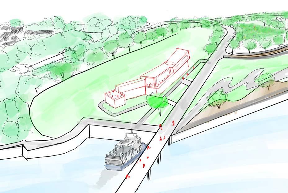
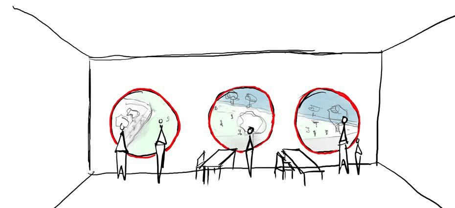
Initial Concepts Sheels Park and Visitor Centre
Re-wilding: Roosts and Meadows
In an effort to re-wild the post-industrial brownfield site as well as providing nesting areas for kittiwakes, the following elements will be added to the site:
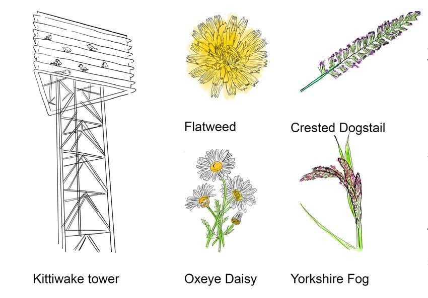
Kittiwake tower: Designed to mimic the natural nesting sites of kittiwakes, these structures will provide easily accessible and undisturbed nesting sites for the birds. The metal pole structural system of these towers also reinforces the contemporary take on post-industrial architecture invoked by the building.
Urban meadow: This protected part of the park will grow wildflowers such as those identified, promoting cross pollination by bees and subsequently aiding the growth of the bee population.
Concept Diagram


Sheels Park and Visitor Centre
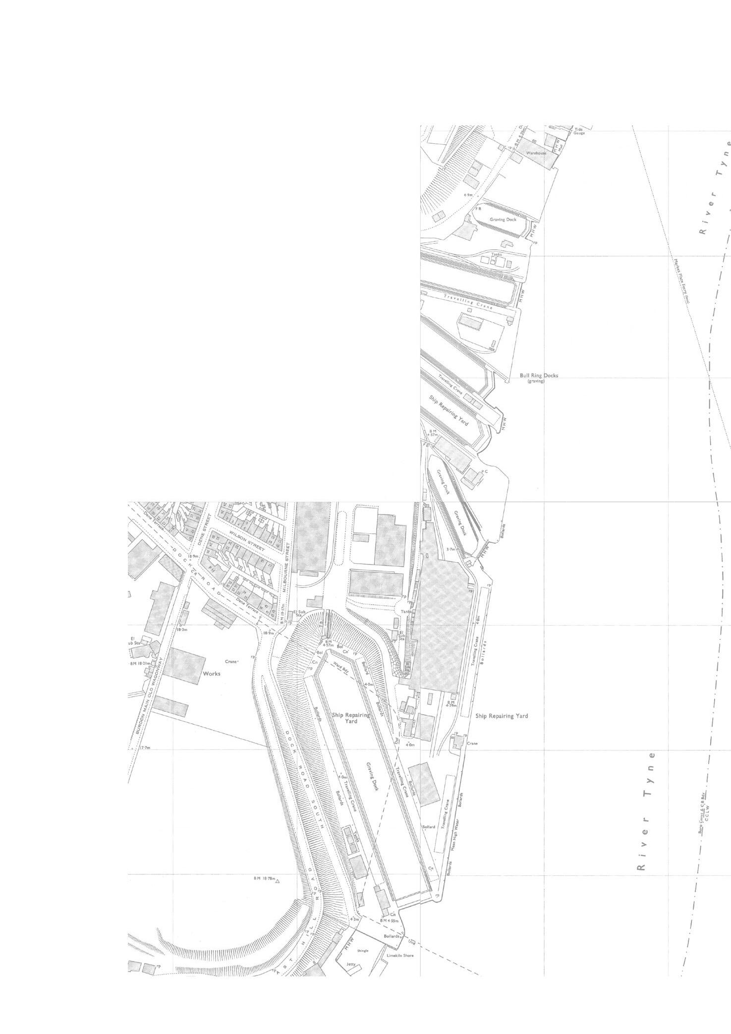
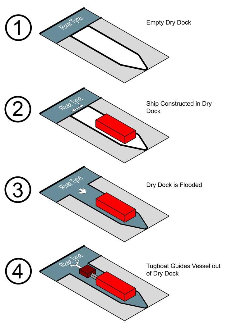
Tugboat and Vessel - Shipbuilding in a Dry Dock
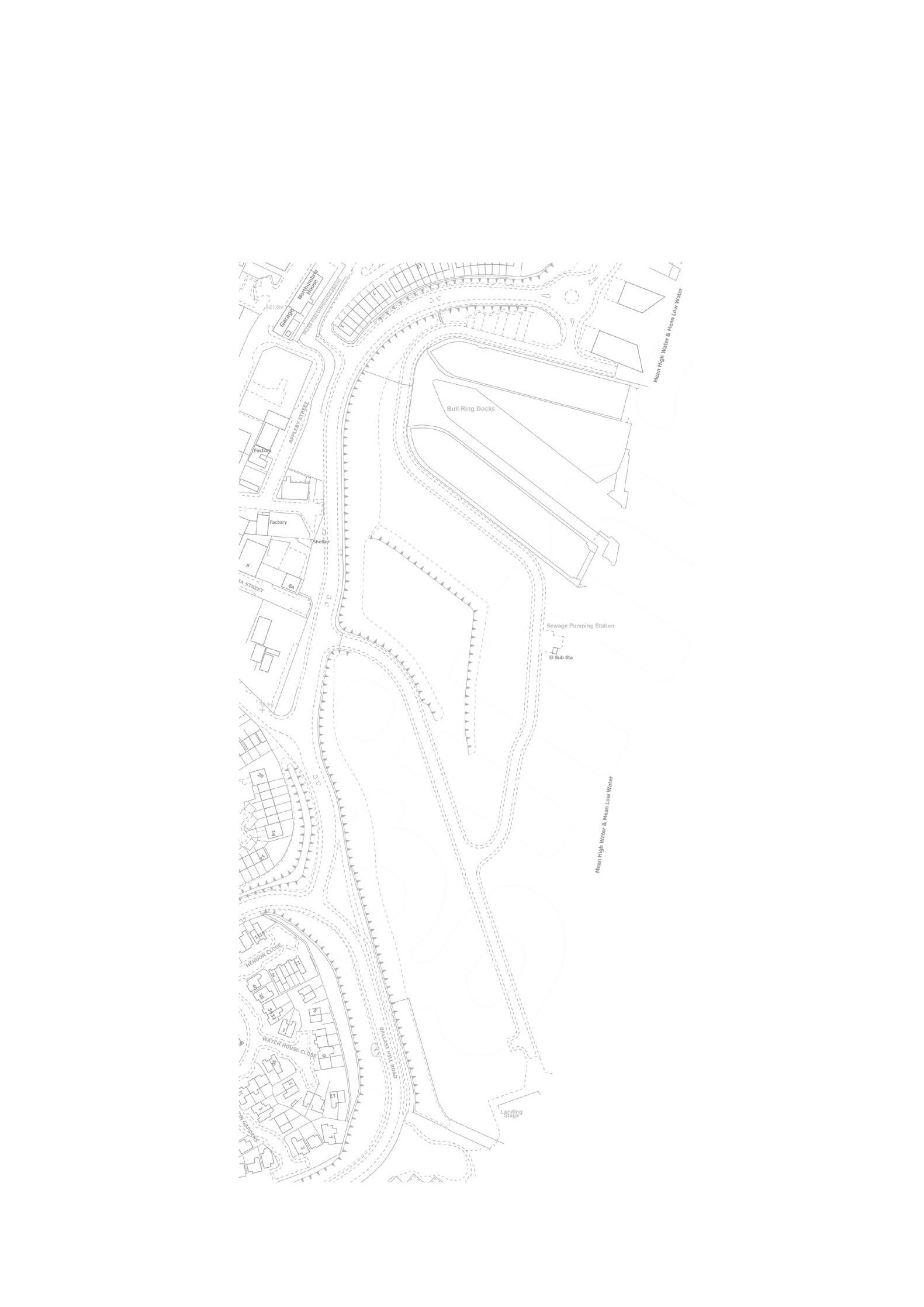
Site Plan - 1950 Site Plan - Present day Overlay and Resolution
Influence - Leveraging Previous Site Footprint
Historical
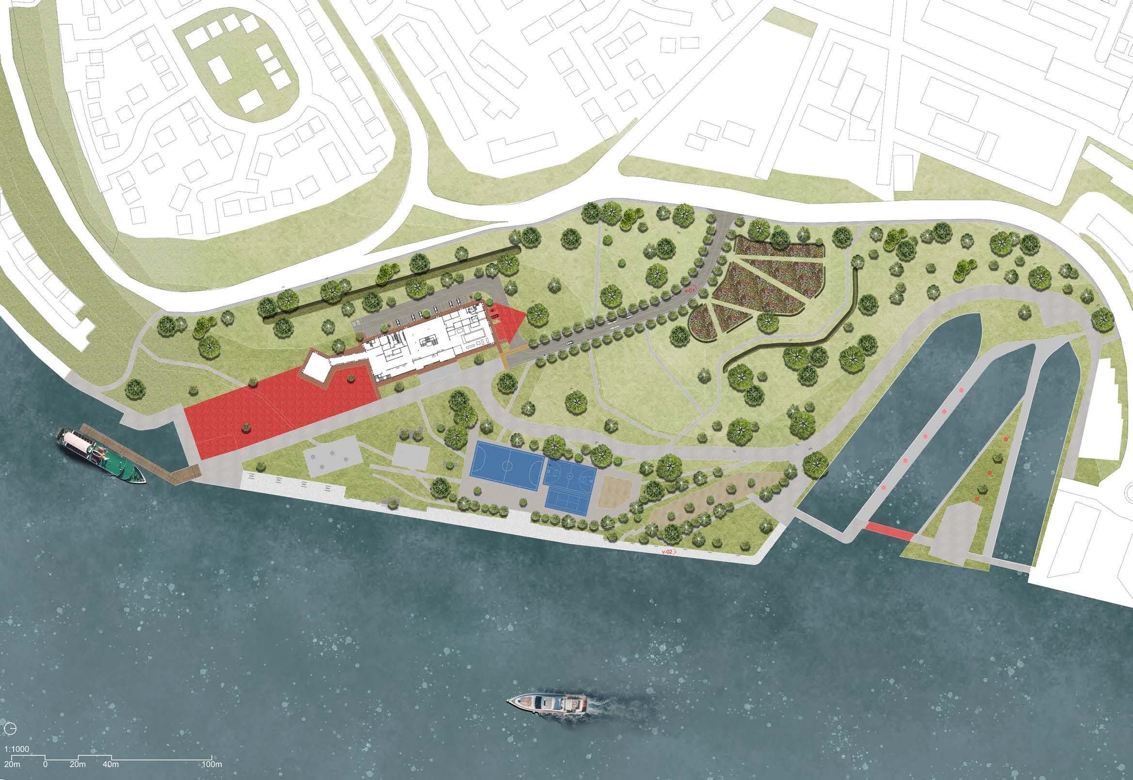 Key
1. Sheels Visitor Centre
2. Rear rain garden
3. Urban meadow
4. Bioswale
5. Mixed transit mode site access route
6. Parking provisions catering for staff, visitors, disabled and cycle parking. Also loading and unloading areas
7. Jetty
8. Playground
9. The Promenade
10. Public multi-purpose lawn
11. Kittiwake towers
12. Pedestrian-only zone
13. Storm-water retention pond
Key
1. Sheels Visitor Centre
2. Rear rain garden
3. Urban meadow
4. Bioswale
5. Mixed transit mode site access route
6. Parking provisions catering for staff, visitors, disabled and cycle parking. Also loading and unloading areas
7. Jetty
8. Playground
9. The Promenade
10. Public multi-purpose lawn
11. Kittiwake towers
12. Pedestrian-only zone
13. Storm-water retention pond
Park and
Centre 1 2 3 4 5 6 7 8 9 10 11 12 13
Site
plan Sheels
Visitor
Sheels Park and Visitor Centre
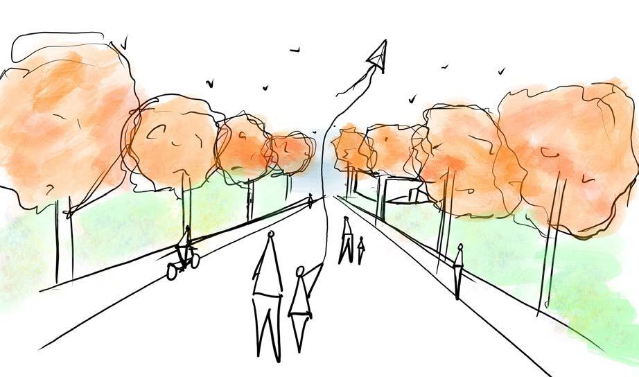
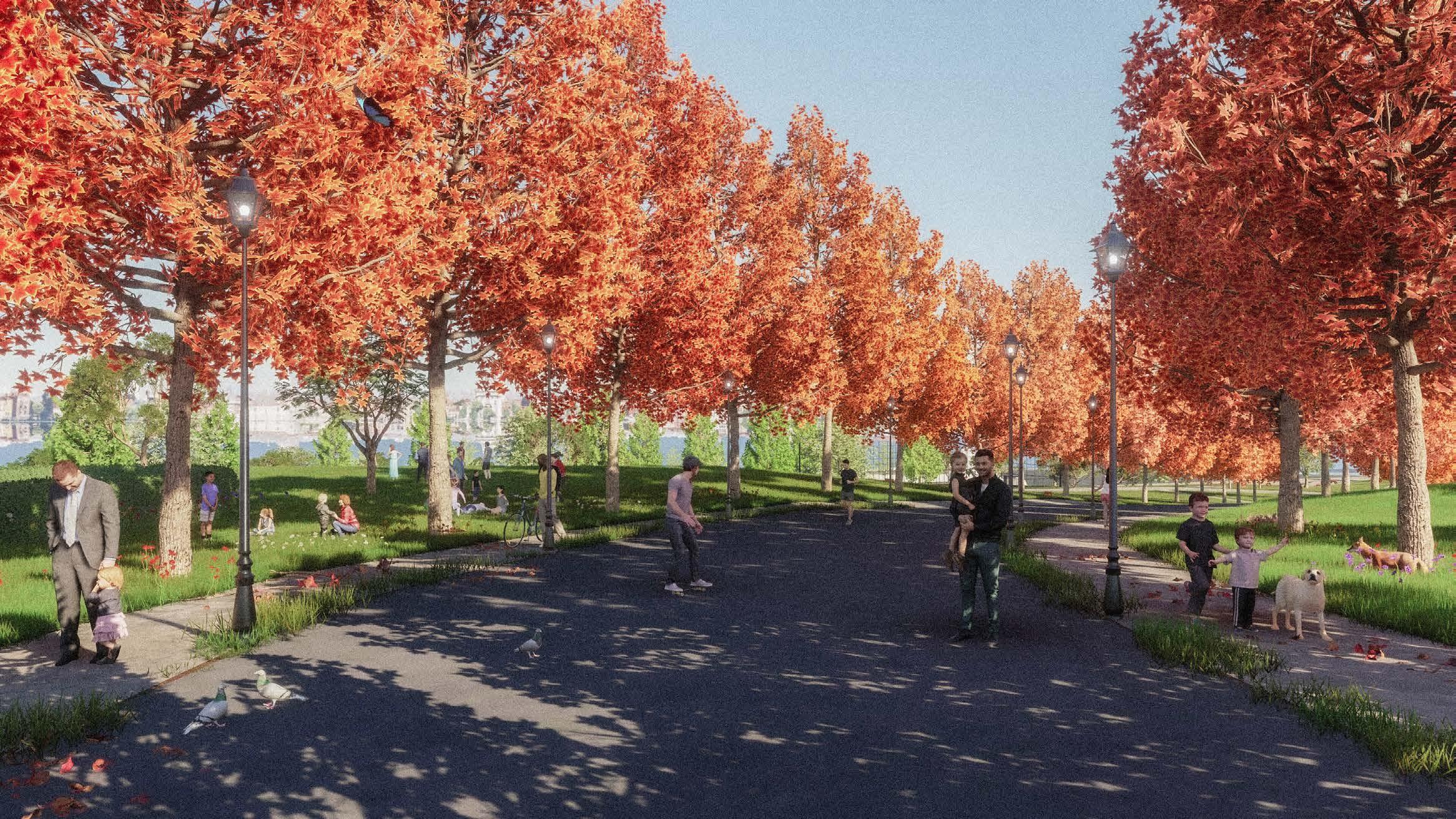
SweetGum Parkway
Characterised by its long row of beautiful American Sweet Gum trees bordering either side of the road, SweetGum Parkway completely engulfs site visitors whether it be pedestrians or cyclists, creating a memorable journey into Sheels Park. A new and unique local landmark.
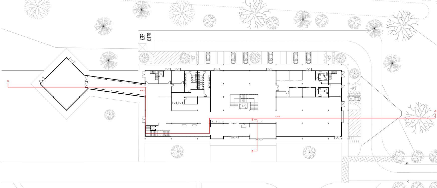
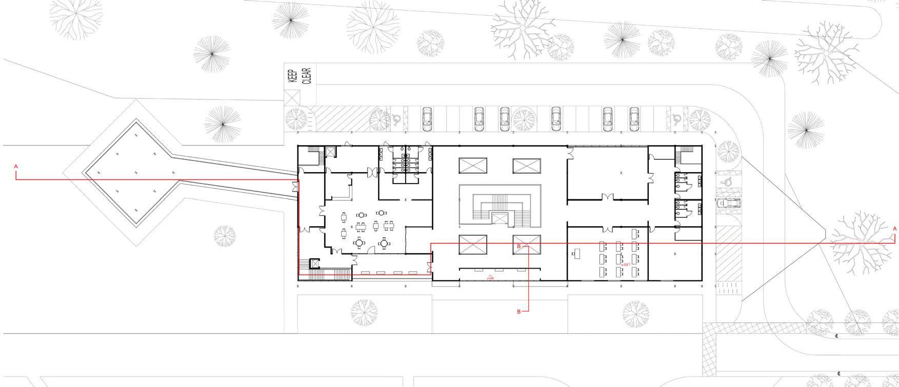
1. Reception / Entrance lobby 2. Shop 3. Atrium / Exhibition 4. Permanent Exhibition 5. Admin. Office 6. Staff break room 7. Meeting room 8. WC 9. Storage / Deliveries 10. Emergency exit 11. Services 12. Maintenance 13. Exhibition 14. Maintenance 15. WC 16. Storage 17. Plant room 18. Staff entrance / Deliveries 19. Emergency exit 20. ‘The Tunnel’ Exhibition 21. Temporary Exhibition 1. Atrium / Mezzanine 2. The Box - Reflection pod 3. Classroom 4. Workshop 5. Storage 6. WC 7. Emergency exit 8. Maintenance 9. Potting nursery 10. Balcony 11. Restaurant 12. WC 13. Services 14. Maintenance 15. Bar 16. Kitchen 17. Emergency exit 18. Bridge 19. The Deck - Pavilion Ground Floor Plan First Floor Plan Sheels Park and Visitor Centre 1 2 3 4 5 6 7 7 8 8 9 10 11 14 13 17 12 15 15 16 18 19 20 21 1 2 3 4 5 6 6 7 8 9 10 11 12 12 13 14 16 15 17 18 19
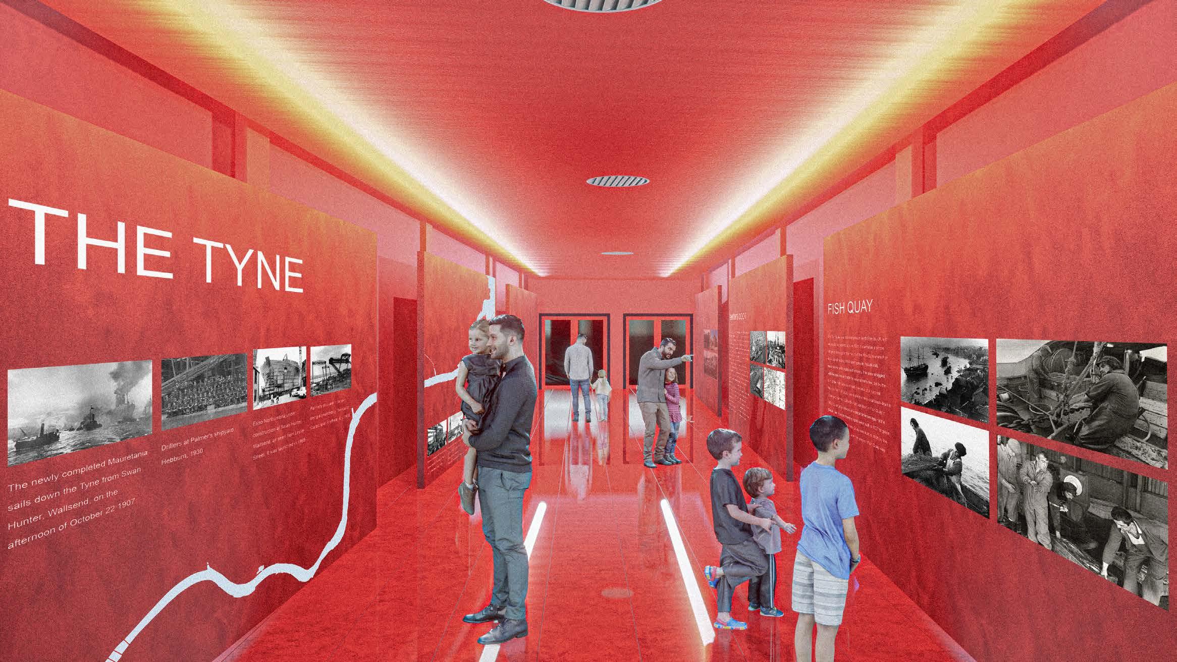
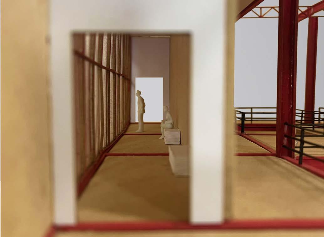
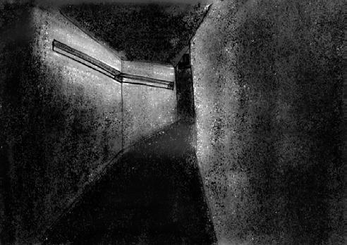
The Tunnel fulfils a multifunctional role, serving as a dynamic exhibition space while also serving as the main access corridor to the special/temporary exhibition area. Within this space, meticulously designed graphic wall displays take centre stage, offering compelling narratives on The Tyne, Smiths Dock, Clifford’s Fort, and the Fish Quay. The strategic use of a vibrant red colour palette, complemented by an elegantly integrated white LED strip lighting along the ceiling, contributes to the creation of a captivating and visually dramatic atmosphere. To augment the immersive experience, carefully curated audio recordings accompany the displayed information, providing visitors with an in-depth understanding and a profound connection to the exhibited content.
Sheels Park and Visitor Centre
The Tunnel Exhibition
Sheels Park and Visitor Centre
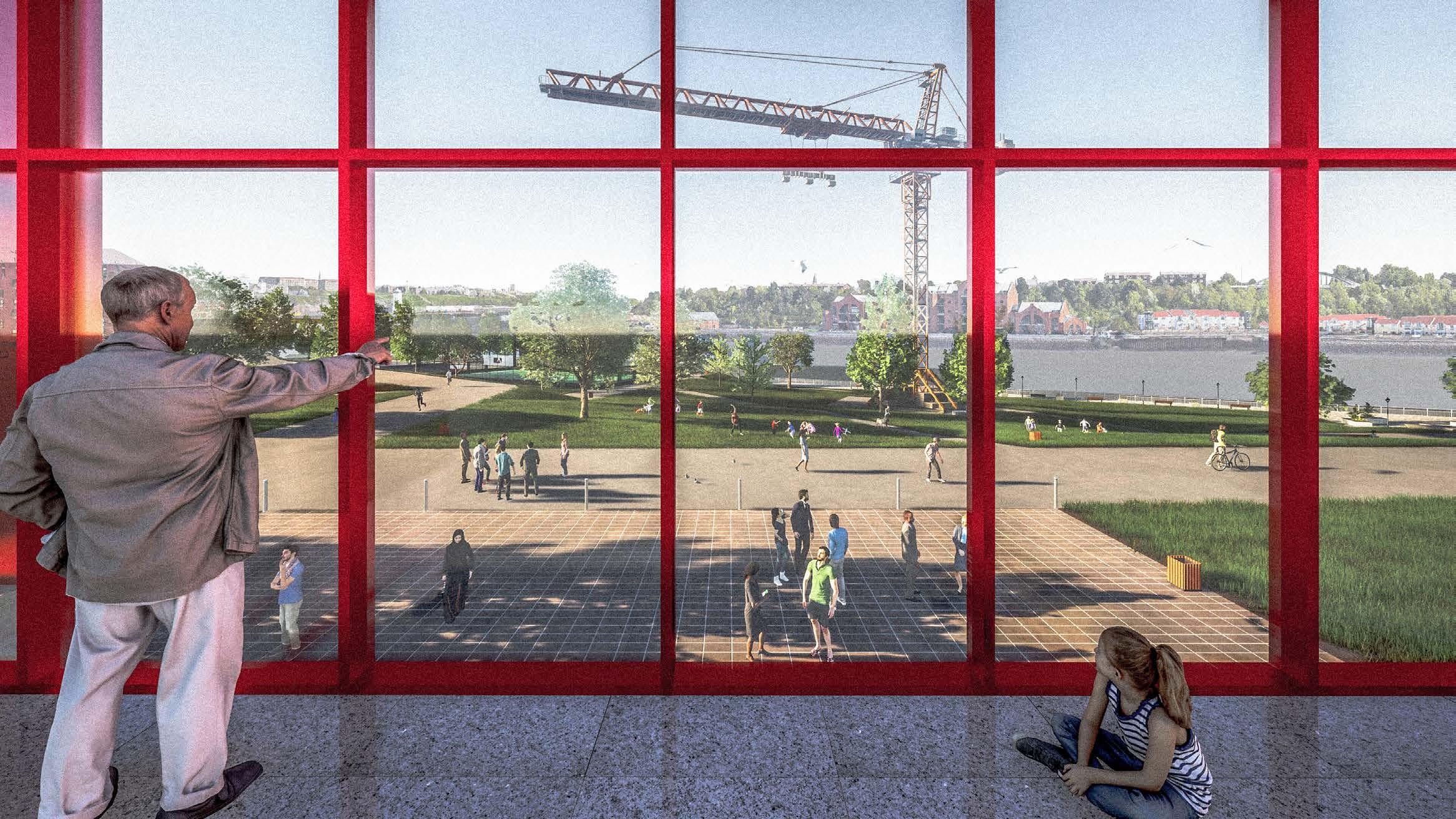
Reflection - ‘The Box’ Overlooking the park and across the River Tyne over into South Shields, The Box provides a moment of pause and reflection for visitors during their journey through the visitor centre. The floor to ceiling height curtain wall frames the entire park, as well as seemingly blurring the threshold between the park and the building, making them into one entity.
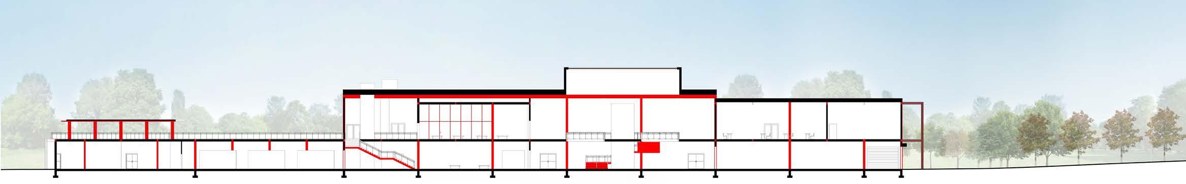
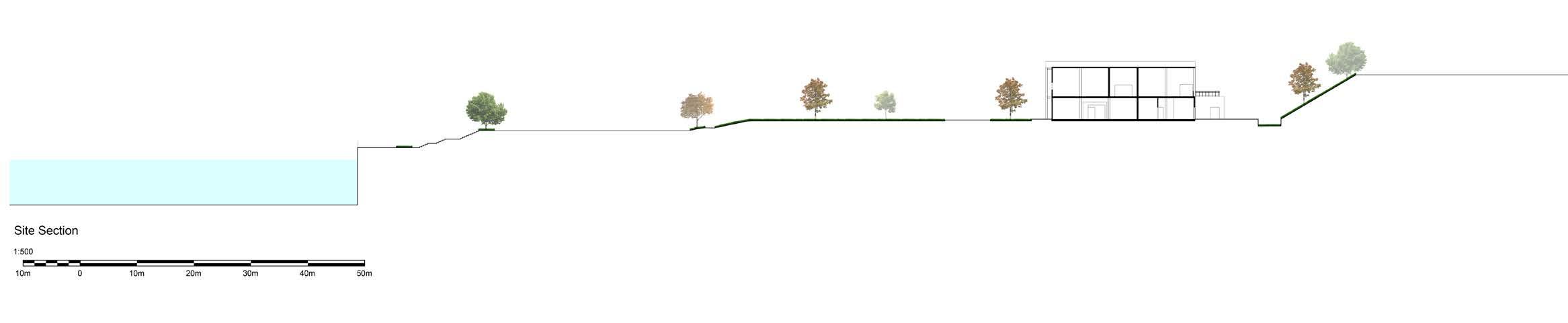
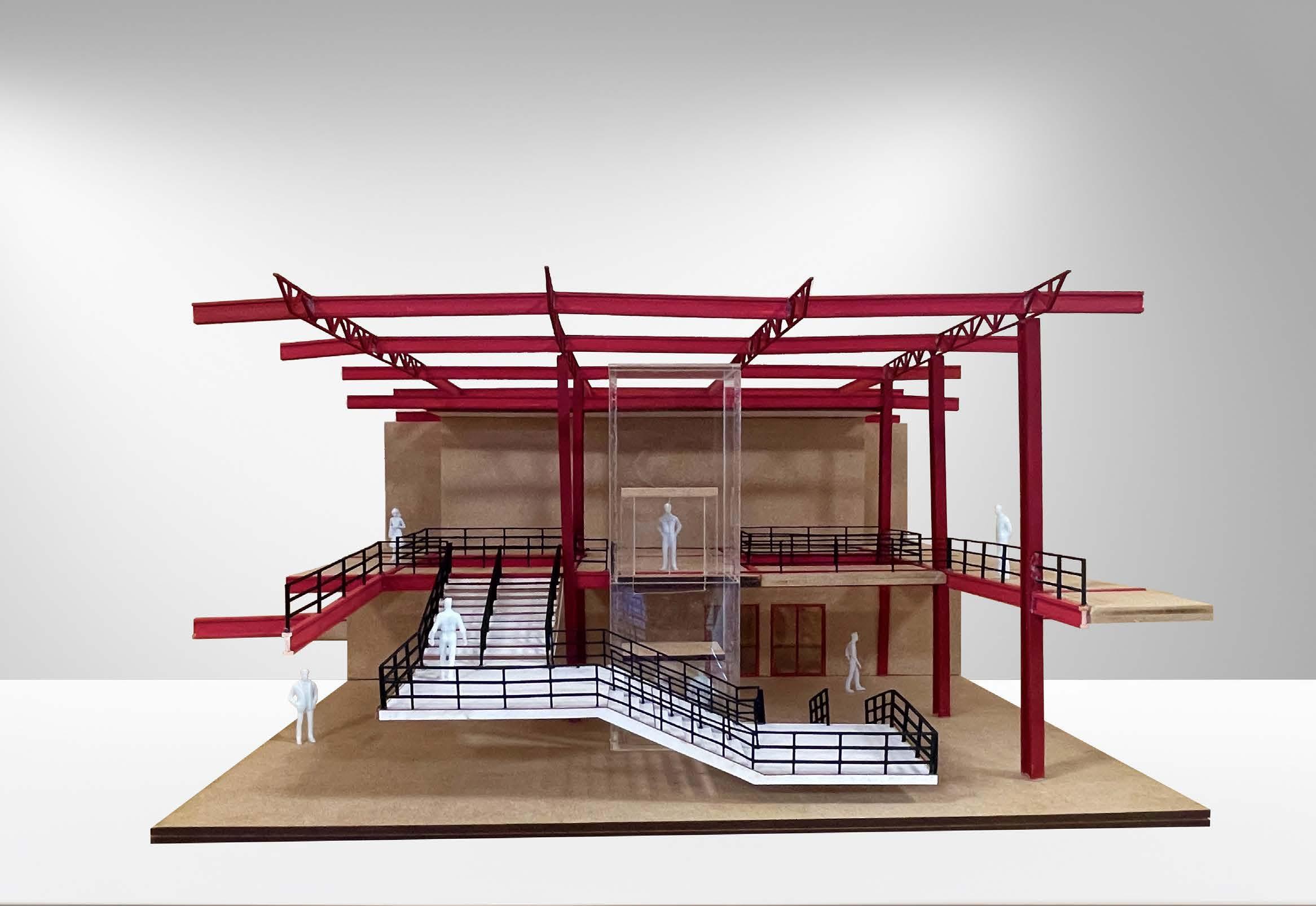
Flood Risk Management and Spatial Arrangement
Terrain slopes are strategically directed to either the rear rain garden, bioswale, stormwater retention pond or the Tyne river. Furthermore, the use of water permeable paving on the hard landscape ensures the controlled drainage of surface water runoff.
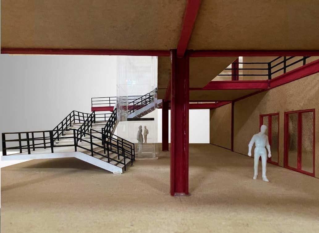
Making the most of the sloping nature of the site’s topography allows for the creation of the staggered terrain levels to create some of the spaces outlined in the programme. It also creates a more engaging and aesthetically pleasing public realm which complements the visitor centre.
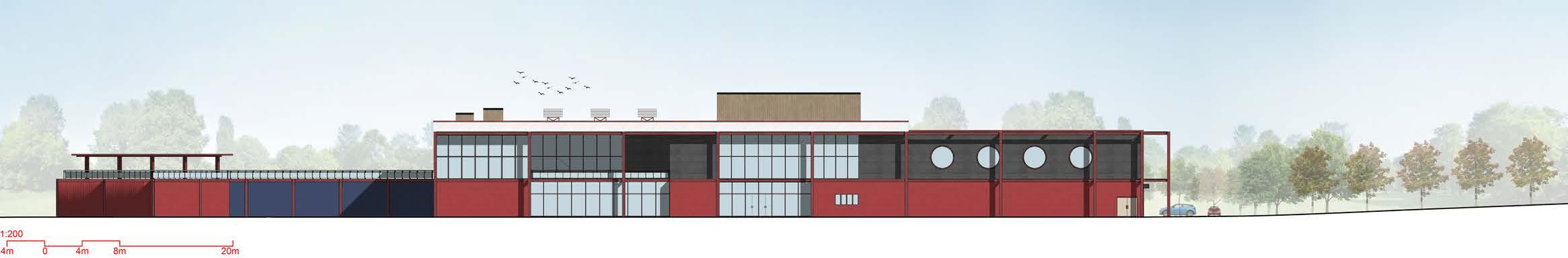
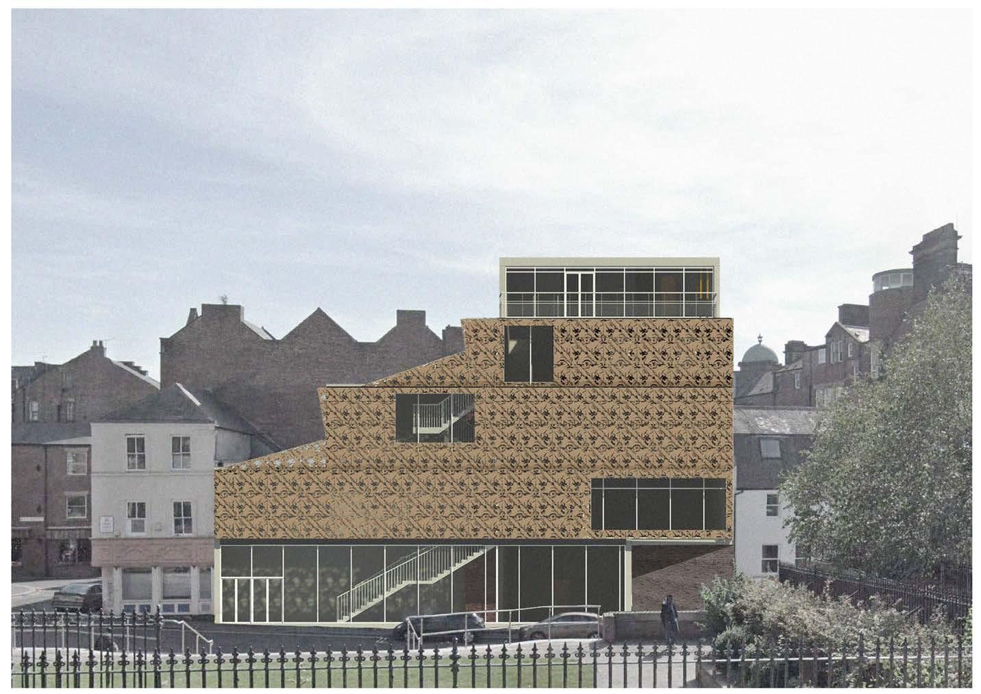
 Principal Elevation
Long Section AA
Principal Elevation
Long Section AA
Sheels Park and Visitor Centre
Site Section
1. Aluminium flashing
2. 12.5mm plywood board
3. Manthorpe Swift Brick
4. Wall ties
5. Masonry
6. Wall tie channel
7. 12mm Class A1 exterior grade sheathing board
8. 75mm Steico Special Dry Wood Fibre Insulation Sarking & Sheathing Board
9. 12.5mm fire rated Gypsum wallboard
10. 65mm Steico Special Dry Wood Fibre Insulation
11. Fully adhered roof membrane
12. Perimeter of roof insulation wrapped in air control membrane to block airflow from roof to parapet
13. 25mm OSB3 Deck board
14. 200mm Rockwool RWA45 insulation
15. Air control membrane
16. Metal deck
17. 50x50mm timber counter battens
18. UB Profile
19. Open web steel joist. Joist spacing: 3050mm, Joist span 10000mm
20. Wind membrane
21. 110mm Rockwool RWA45 insulation packed between individual steel channels
22. 122mm C section steel profile - Material and tolerances - Gauge to conform to BS 10143 - ‘special tolerances’, Material to conform to BS EN 10346
23. Proprietary Lintel & Cavity tray to brick external leaf
24. Stone mineral wool fillers
25. x2 12.5mm knauf gypsum wallboard
26. Rockwool RWA45 insulation packed around structural steel beam preventing thermal bridging and for additional fire protection
27. 75x220mm timber joists attached to beam through means of a top flange joist hanger
28. 45x45mm timber counter battens
29. x2 15mm gypsum board
30. Timber stud wall construction
31. Triple glazing
32. Lightweight vegetation
33. Growing medium
34. Drainage element, water reservoir and root barrier
35. Filter fleece
36. Retention trim
37. Smooth gravel edge channel min. 150mm
38. Waterproof membrane
39. 300 ASB249 Profile
40. 20mm edge insulation
41. 800x800mm Marmy grey marble effect polished porcelain floor tiles
42. 45mm lightweight screed
43. 75mm Kingspan GreenGuard GG300 XPS insulation
44. 5mm impact soundproofing
45. 200mm precast concrete deck
46. x2 15mm mineral tile suspended ceiling
47. Suspended ceiling hangers
48. Galvanised steel and glass balustrade
49. Parapet coping
50. 25mm Kingspan GreenGuard GG300 XPS insulation
51. Deflection head
52. Aluminium sill sheet
53. Insulated cavity closer
54. x2 12.5mm Knauf gypsum wallboard
55. Concrete strip and reinforced footing foundation
56. 25mm Edge insulation
57. 120mm XPS insulation
58. x2 100mm and 120mm Jackodur XPS foundation insulation 600mm x 1250mm
59. 300mm reinforced cast-in-site concrete slab
60. Permagard PermaSEAL Damp proofing membrane
61. Gutta dimpled membrane with filter fabric drainage mat and sliding film. The sliding film on the membrane effectively eliminates potential point load
62. 107mm lightweight levelling screed
63. 600x600mm square matte white ceramic floor tiles
64. Raised access floor support pedestals
65. 200mm FOAMGLAS slabs, laid with PC 58
66. Flooring panels
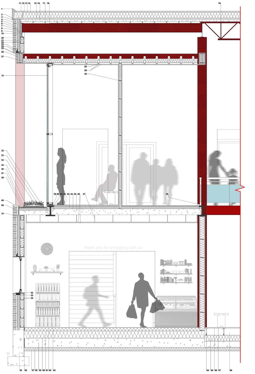
67. Herringbone parquet timber floor finish
68. Raised access floor cavity to house electrical cables and underfloor air distribution
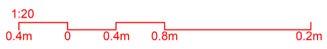
Construction Section BB
Skills: Revit, AutoCAD, Adobe Photoshop, Technical knowledge
Sheels Park and Visitor Centre
Building Model - Atrium Sheels Park and Visitor Centre
Building Model - Atrium Sheels Park and Visitor Centre
THE MOTHERLAND PROJECT
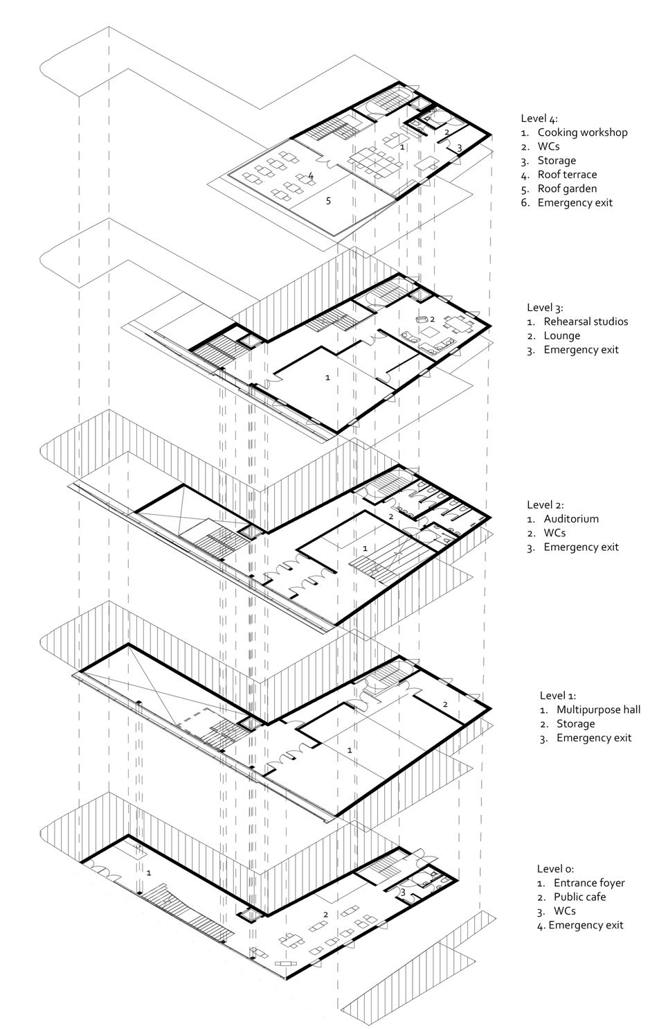
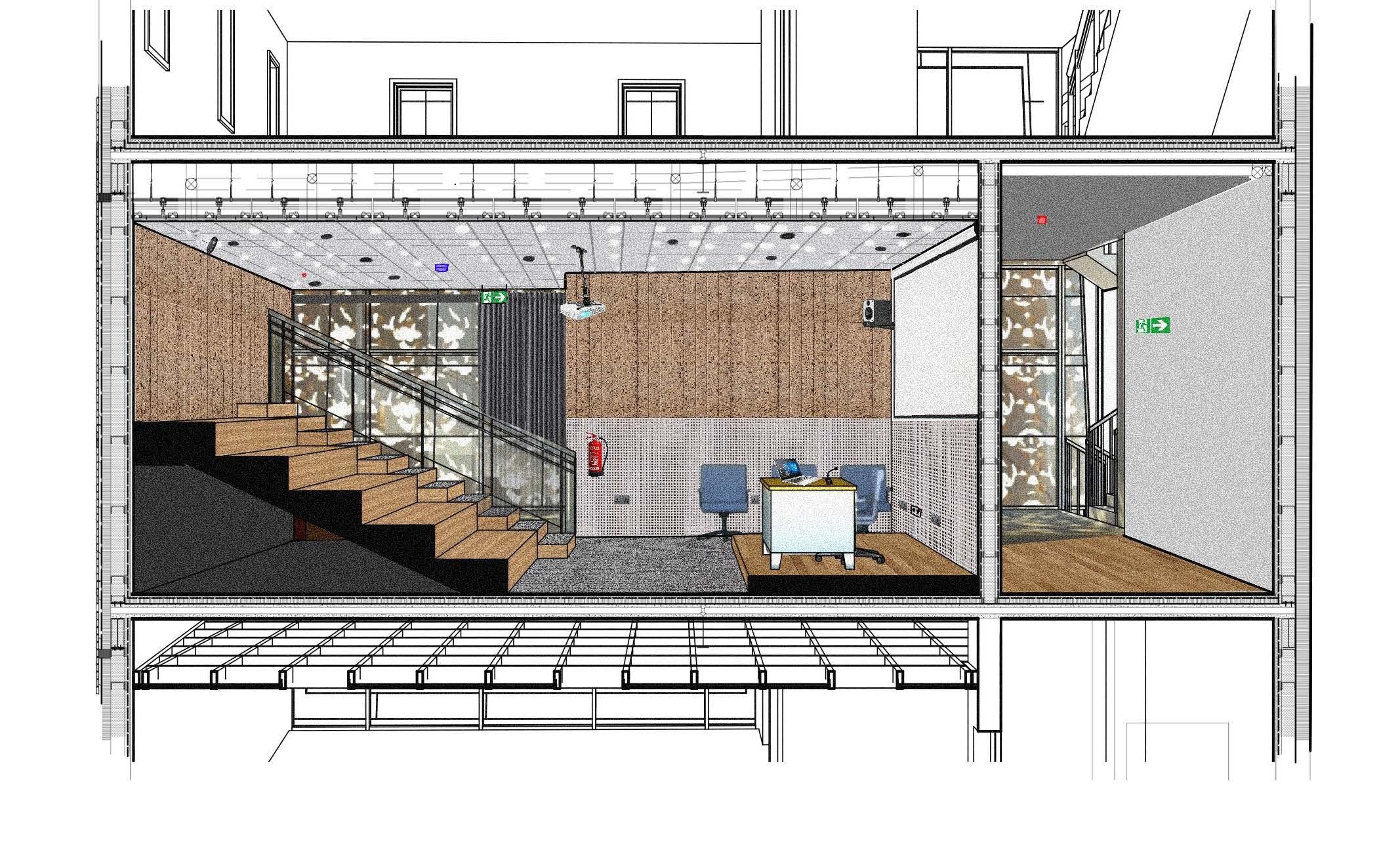
The Motherland, situated in the heart of Newcastle Upon Tyne is a cultural hub for the appreciation of African-Caribbean heritage in the North-East. Through careful consideration of form and materiality, it is designed to draw on the heartstrings of people of Afro-Caribbean descent living in the diaspora - A home away from home. Furthermore, the Motherland through strategic design and programming, aids in promoting cultural integration between the different cultural communities living in the North East. By providing key spaces such as a Public Cafe, Auditorium, Performance Hall, Rehearsal Room and a Cooking Workshop space, members of the community, regardless of cultural background will be provided with the opportunity to make appropriate use of the required space, and in the process will also begin to learn more about African-Caribbean culture. Through all this, the Motherland project will successfully accomplish its agenda of Representation and Education of and on African-Caribbean culture.
Site Information
Site: Charlotte square
Address: 5 - 7 Cross Street, Newcastle upon tyne, UK NE1 4X3
Building footprint: 230m2
Principal Elevation
2 The Motherland Project
Site Strategy
Skills: Model Making, Critical thinking, Visualisation
Bioswales located within the courtyard space will help slow down the rate of surface water runoff on the existing hard landscape
Existing interior courtyard will be repurposed to create a more intimate semi-public space to be used primarily by users of the building but can also be accessed by the public
Pedestrianised section of cross street and the introduction of greenery/biodiversity in the form of a soft landscape will aid in the mitigation of the lack of biodiversity in the general site region
Hard landscape integrated with pedestrianised section of public realm
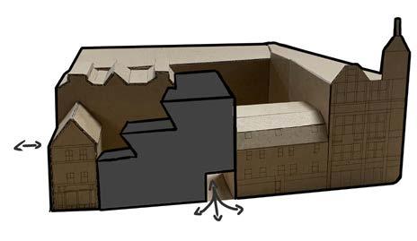
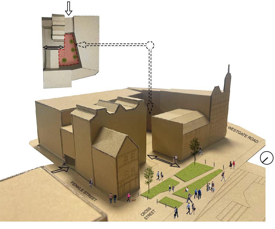 Alternative courtyard access via Fenkle Street from the North of the site
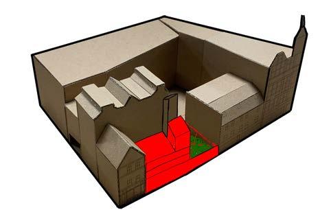
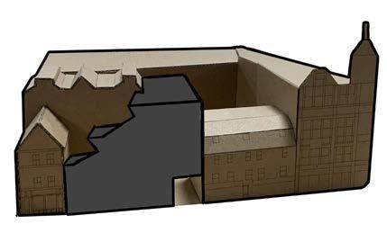
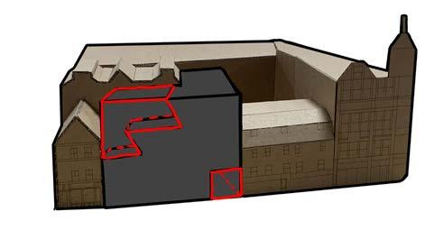
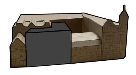
Massing Development The Motherland Project
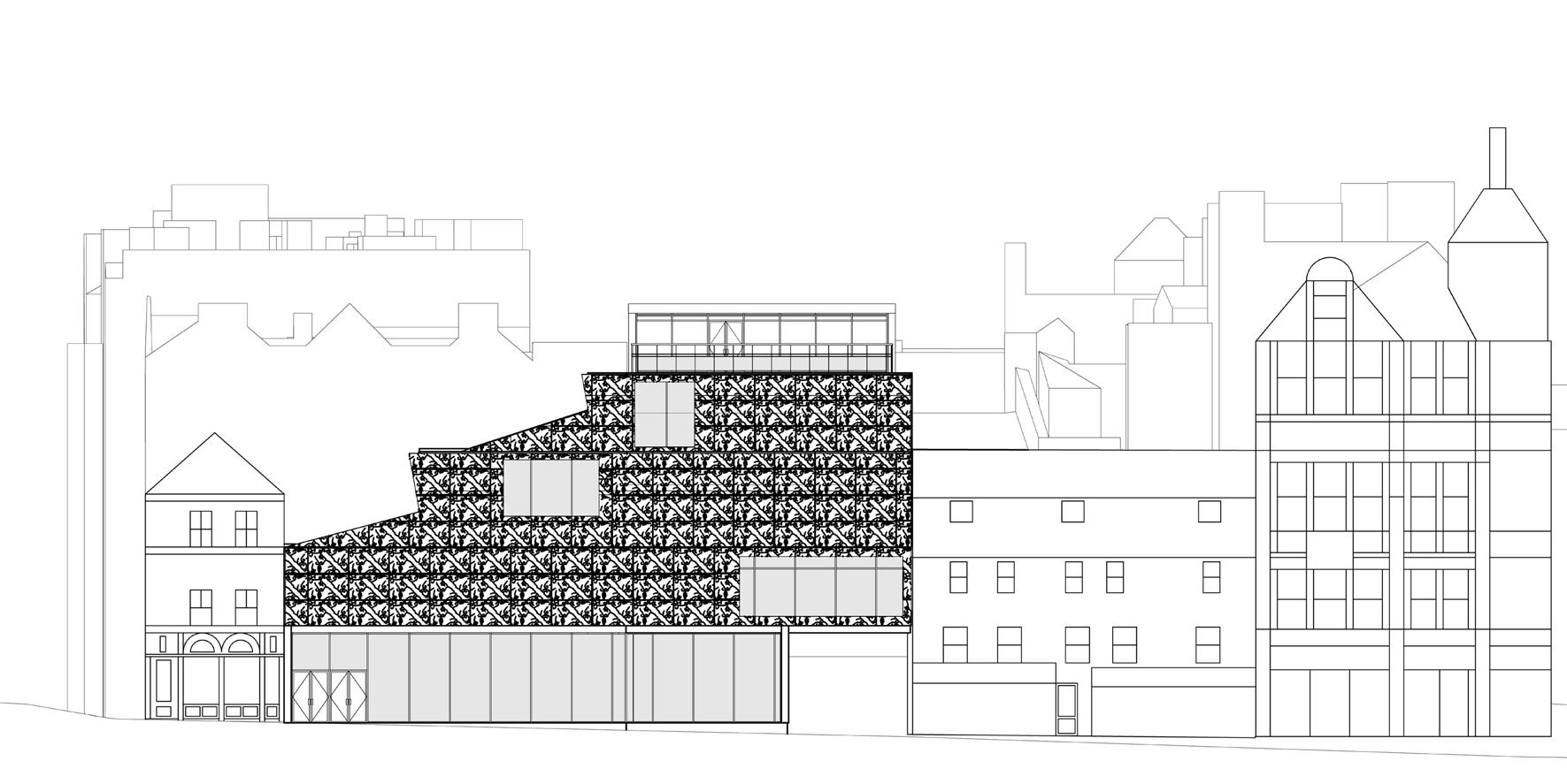 Front Elevation
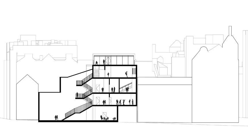
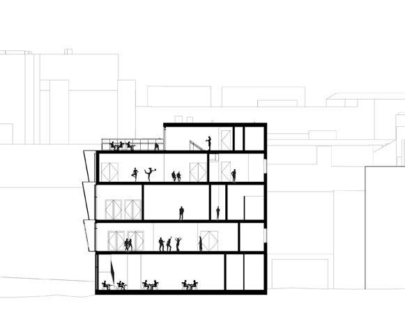
Long Section
Front Elevation
Long Section
The Motherland Project
Cross Section
Exploded Axonometric Drawing
Skills:
Exploded Axonometric Drawing: Floor Plans and Circulation
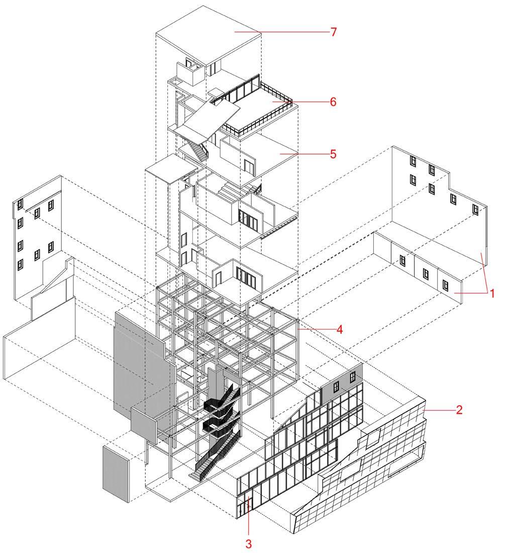 1. External wall - Light steel infill wall with stofix brick-slip cladding on exterior
2. Double-skin facade - 'Corona panels'
3. Double-skin facade - Curtain wall system to required specs.
4. Structural framing - Steel framed construction
5. Floor - 125mm reinforced pre-stressed hollow core concrete slab
6. Accessible roof terrace
7. Roof - Low slope flat roof (warm)
1. External wall - Light steel infill wall with stofix brick-slip cladding on exterior
2. Double-skin facade - 'Corona panels'
3. Double-skin facade - Curtain wall system to required specs.
4. Structural framing - Steel framed construction
5. Floor - 125mm reinforced pre-stressed hollow core concrete slab
6. Accessible roof terrace
7. Roof - Low slope flat roof (warm)
The Motherland Project
Revit, AutoCAD
1:5 Detail: External Wall and Ground Floor Junction
1. 10mm ceramic tile flooring
2. Tile adhesive
3. 40mm lightweight screed
4. 100mm reinforced concrete slab, 15 MPA
5. Permagard PermaSEAL Damp proofing membrane
6. 220mm Jackodur XPS foundation insulation 600mm x 1250mm
7. Gutta Dimpled membrane with filter fabric drainage mat and sliding film. The sliding film on the membrane effectively eliminates potential point load
8. 200mm gravel drainage with reused bricks from demolished existing site construction (as discussed in sustainability criteria)
9. Membrane flashing covered with skirting board
10. x2 12.5mm Knauf Gypsum Wallboard
11. 203 x 203 x 46mm Universal column
12. Rockwool RWA45 insulation packed in to steel column for fire protection around the column and to prevent cold bridging in column junction
13. x2 12.5mm fire-rated Knauf Gypsum Wallboard for added fire protection around steel column
14. 25mm cavity
15. 20mm stofix brickslip cladding
16. Factory applied mortar
17. Fillet weld
18. Stainless steel flash washer M12
19. Site applied mortar
20. 25mm Stofix horizontal rail holds the brickslip panels attached to the light steel infill wall construction (see ground floor plan)
21. 160 x 160 x 10mm S275J0 C1 Base plate
22. 20mm Grouting
23. Steel anchor M12 x 250mm class 4.8
24. Concrete strip foundation
25. Light concrete curb fabrication to protected external foundation insulation
26. Kingspan GreenGuard GG300 XPS insulation around foundation
27. Concrete paving (external landscaping)
28. Compact sand drainage layer
29. Aggregate drainage from demolished existing brick construction on site
30. 300mm gravel filter
31. Drain pipe connected to sewer system
32. 710 x 300mm Reinforced cast-in-site concrete footing
The Motherland Project
1:5 Detail: External Wall to Roof Junction
1. Light infill steel wall construction
2. 5.5mm TEK screws (EU approved standard)
3. Dense mineral wool between primary steel beam and light steel channel
4. Eurosteel UB090 254X102X22 UB coated in intumescent fire coating
5. Rockwool RWA45 insulation packed around structural steel beam preventing thermal bridging and for fire protection
6. x2 12.5mm Knauf GypsumWallboard for added fire protection around structural steel beam
7. M12 steel bolt holding steel roof joist attached to primary beam
8. 65mm Steico Special Dry Wood Fibre Insulation
9. Mild steel end cap welded to end of structural parrallel flange steel roof joist
10. 200x75x23mm Rainham steel Parallel flange C Channel roof joist coated in intumescent fire coating at 3400mm centres
11. 45x45x3400mm horizontal counter battens at 400mm centres to be attached to steel joist
12. 15x1200x600mm suspended ceiling tiles (tiles do not cover sections occupied by steel joist which will be exposed)
13. Suspension rod bracket fixed to the side face of counter battens as shown at 1200mm centres. Use suspension rod angle bracket where fixing to the side of batten is not possible
14. Suspension rod
15. Suspension clip
16. 45mm Steico Special Dry Wood Fibre Insulation
17. 25mm OSB3 Deck board
18. 250mm Rockwool RWA45 insulation
19. Spray foam insulation
20. 15mm Plywood sheathing board
21. KEMPEROL 165 fleece membrane
22. 25mm 0SB3 board
23. PVC membrane
24. Over-framing for slope (minimum fall of 1:40 according to BS 6229 & BS 8217)
25. Drain
26. Parapet cap
27. 50x100mm timber parapet / Stucco stop-overhang wall by 15mm
28. Rim board per mfg instructions
29. Rockwool RWA45 insulation packing
30. 15mm Stucco over weather resistive barrier
31. Perforated 25mm structural plywood deck for downpipe
32. GI Corner bead
33. 65mm diameter anodised steel downpipe
The Motherland Project
The Motherland Project
Perspective section detailing Intergration of services
ECOSPHERE - A MUSEUM OF EXTINCT SPECIES
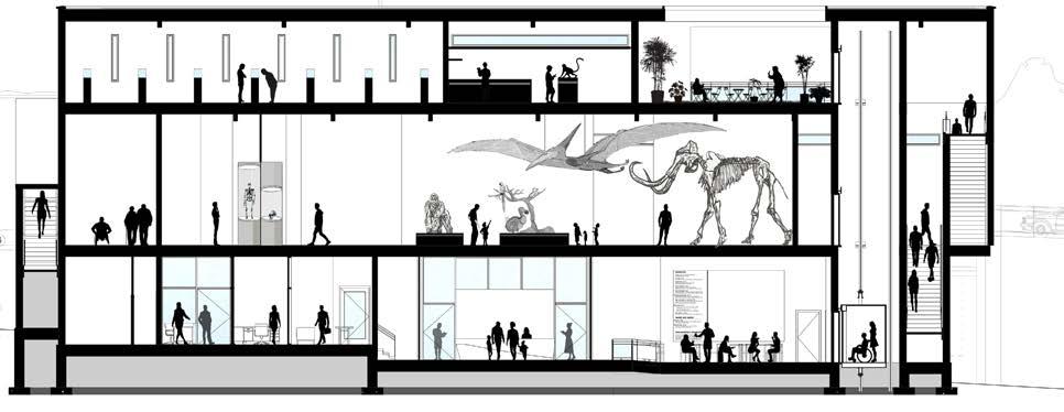
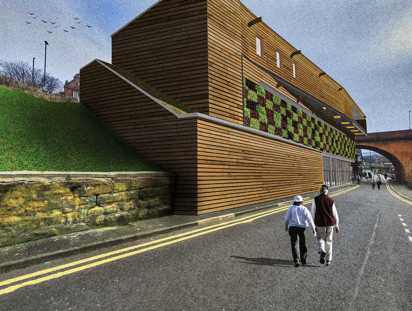
In a predominantly brick-heavy area like the Ouseburn, my design proposal for the Museum of Extinct Species - ECOSPHERE, seeks to take a bold approach to addressing the climate crisis through means of a controlled museum experience and use of sustainable construction materials, making for a low carbon building. Its out-of-place timber cladding, along with incorporated elements like living walls and green roofs, creates a structure in complete contrast to the buildings and structures that surround it. The reason behind this design decision is to reinforce the scientifically proven fact that our planet is dying due to the negative effects of global warming and serious action must be taken soon in order to effectively mitigate the environmental impact it poses. This design proposal is a representation of an action driven initiative to tackle climate change.
Site Information
Site: Back Maling Street

Address: Back Maling Street, Ouseburn, Newcastle upon tyne
3
Exterior Perspective
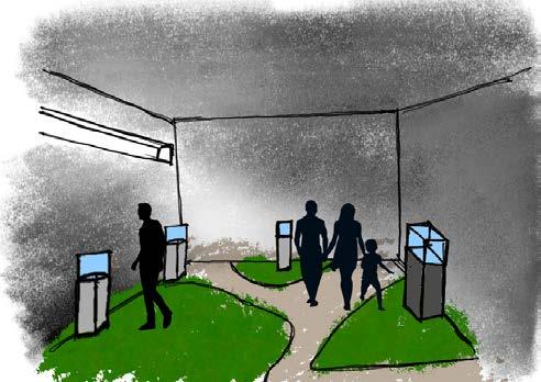
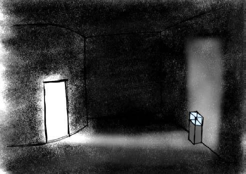
Atmospheric ambitions for key interior spaces
ECOSPHERE - A Museum of Extinct Species
Long Section
Architectural Technology and Design
Year Abroad - VIA University College
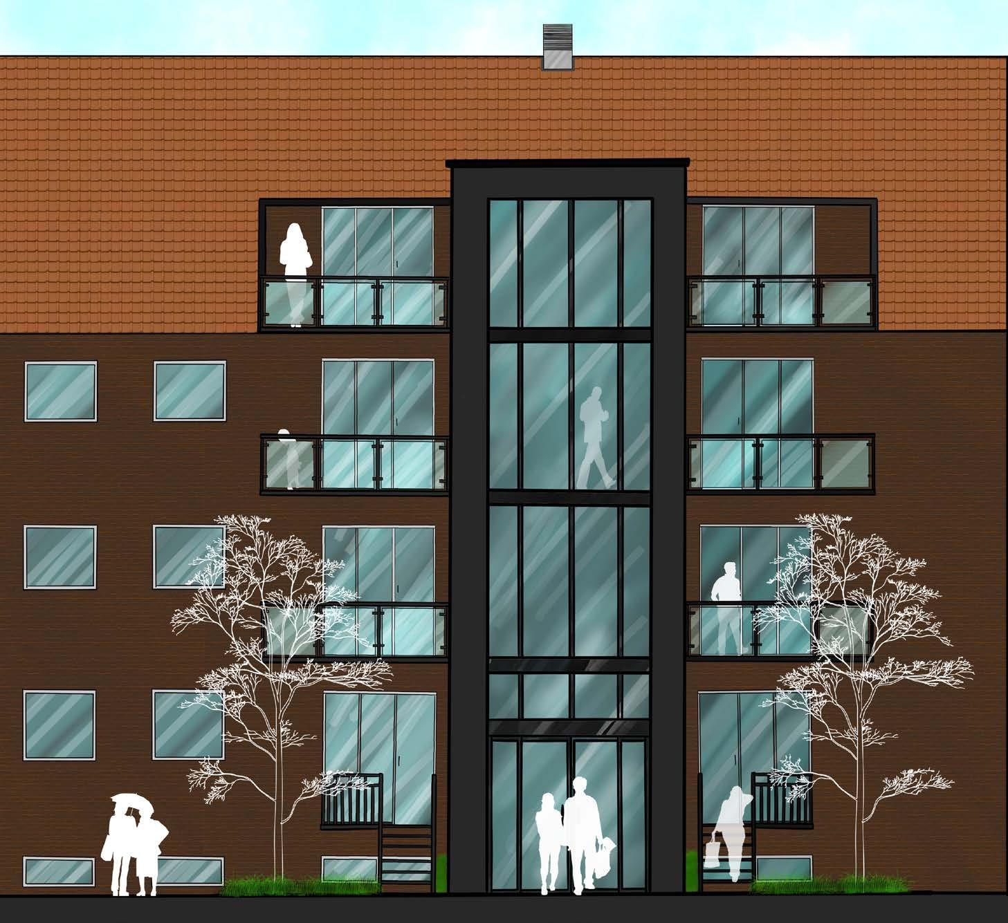
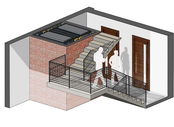
The renovation project for Østerled 3 in Horsens, Denmark, involves enhancing the building’s infrastructure. Accessible via Østerled and Ostergaards Way, parking areas are conveniently located on the western side near the road. With a gross area of 1809.6m2 (1425 m2 excluding the basement), the building comprises eight types of apartments ranging from one-bedroom to three-bedroom, spanning 60m2 to 109m2. The primary structural design incorporates a façade load-bearing system responsible for supporting the roof, storey partitions, and adjacent walls. The facade and gables are being insulated to meet requirements. A truss system insulation and clay tiles constitute the cold roof. Upgrades to the storey partition ensure sound compliance, utilising HEB steel profile beams. Additionally, an elevator and a steel frame extension are being added to the building.
Site Information
Site: Østerled 3a - 3b
Address: Østerled 3a - 3b, Horsens, Denmark
4
and
Architectural
Technology
Design
Front Elevation Hand Rendering
Architectural Technology and Design
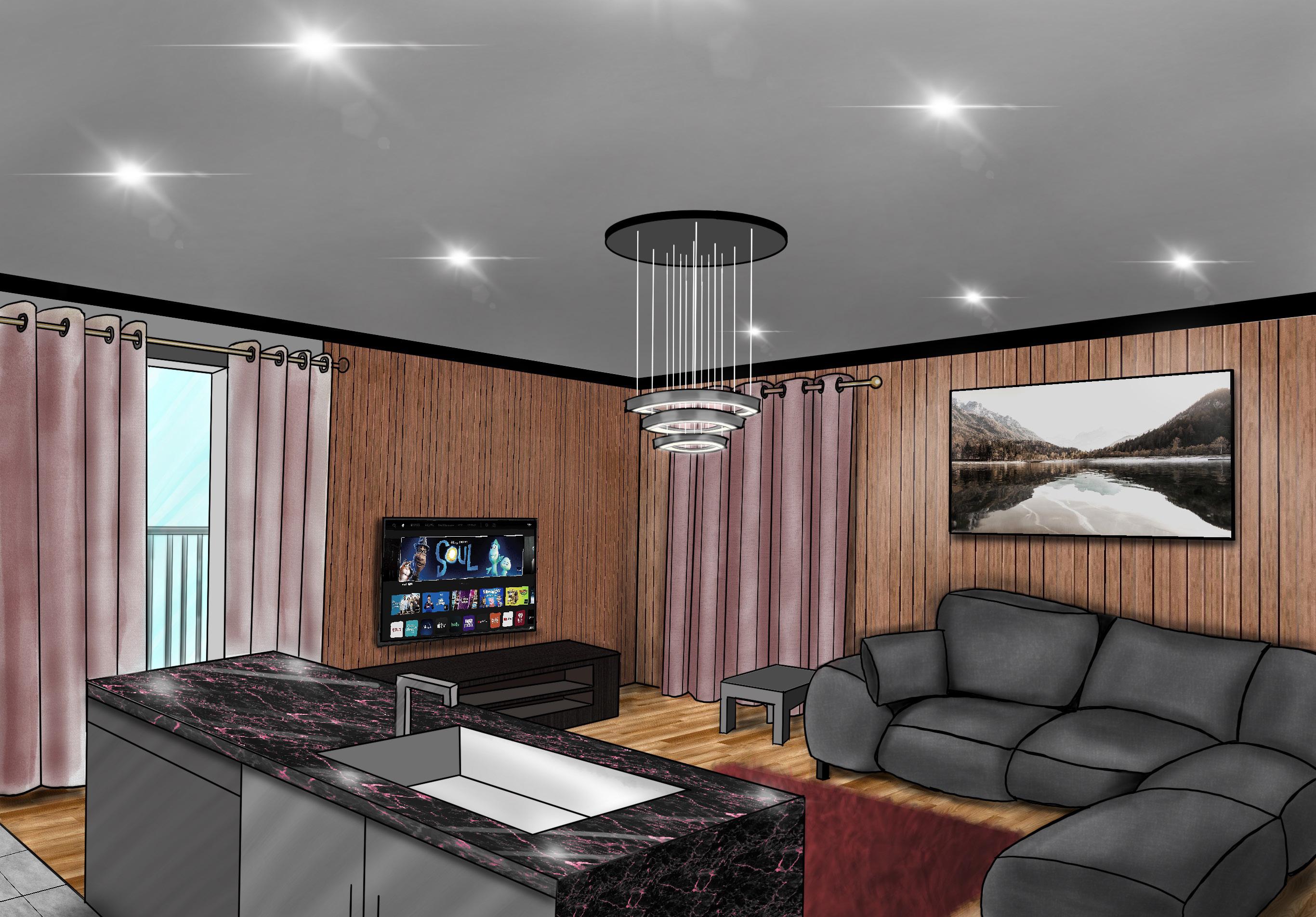
One Bedroom Apartment Interior Perspective Hand Rendering
5
Urban/Regional Planning and Design
Year Abroad - Florida Atlantic University
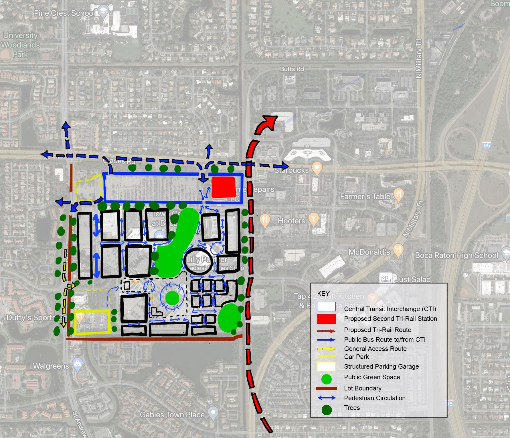
Boca Raton Downtown Redevelopment Plan
The redesign of the town (Boca Raton) centre mall, incorporating smart growth principles, walkability, and transit-oriented development, is a key component of the 10-year planning strategy for this study area. The accompanying illustration demonstrates the proposed Central Transit Interchange's location in relation to the revamped mall, the proposed Tri-Rail route/station, and Glades Road. The interchange has been strategically positioned to facilitate seamless bus access and egress from the central hub. Furthermore, the redevelopment plan entails a complete restructuring of the mall, prioritising pedestrian-friendly spaces and public green areas where shoppers can rest and unwind. In line with the transit-oriented approach, parking provisions have been significantly reduced, offering a smaller car park and structured parking. This shift aims to encourage public transit usage, as parking spaces will no longer be guaranteed.
Site Information
Site: Downtown Boca Raton
Address: Boca Raton, Florida, USA
Redevelopment Strategy
Urban/Regional Planning and Design
Masterplanning Strategy
Burke Lake-front Airport Retrofit Plan
Burke Lake-front Airport (BKL) in Cleveland, Ohio decommissioning and retrofit plan encompasses the following enhancements:
1. Establishing a new mixed-use development on the former airport land to optimize its utilization efficiently.
2. Creating a waterfront promenade encircling the new development, offering a pleasant walking path along the water's edge.
3. Incorporating expansive public green spaces between the water and the development, providing serene natural areas.
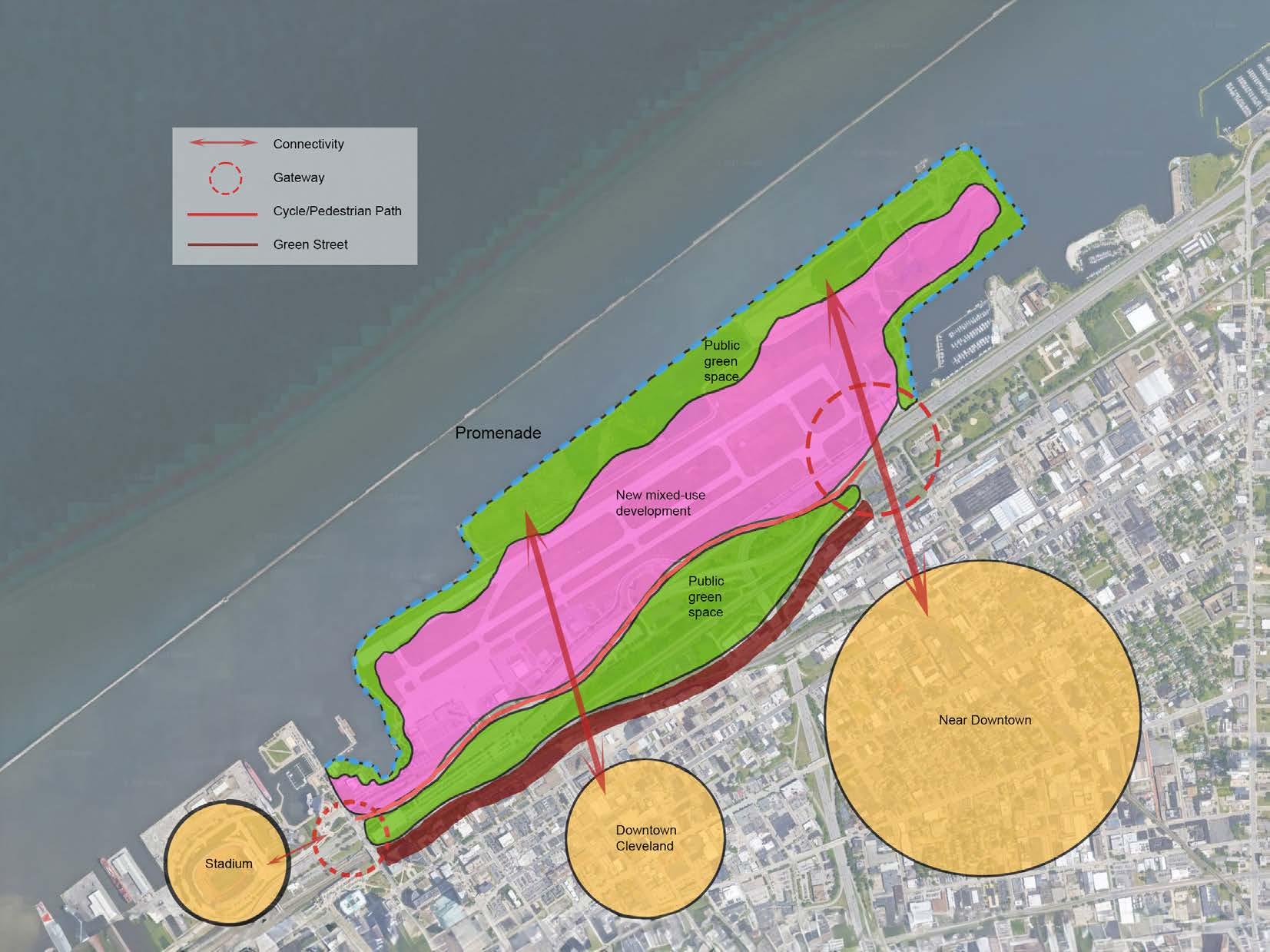
4. Ensuring convenient access to the new development from the downtown and nearby areas.
5. Establishing safe pedestrian connections between the new mixeduse development, downtown/near-downtown areas, and the stadium through a pedestrian-friendly environment.
6. Diverting the main road between the airport and downtown beneath the downtown area, supporting the implementation of point .
7. Transforming the main road between the new development and downtown into public green spaces and a green street, serving as a vital link connecting the downtown, near-downtown, new mixed-use development, and stadium areas.
8. Prioritizing public involvement in every phase of the retrofit plan, fostering community engagement and input.
Site Information
Site: Burke Lake-front Airport
Address: Burke Lake-front Airport, Cleveland, Ohio, USA
Urban/Regional Planning and Design