PATRICK D. DILLON
GRADUATE PORTFOLIO
MASTER OF ARCHITECTURE 2024
MASTER OF SCIENCE IN ARCHITECTURAL STUDIES, STRUCTURES OPTIONS 2024
BACHELOR OF SCIENCE IN ARCHITECTURAL STUDIES 2021
UNIVERSITY OF ILLINOIS AT URBANA-CHAMPAIGN
VOLUME IV

02 INTRODUCTION
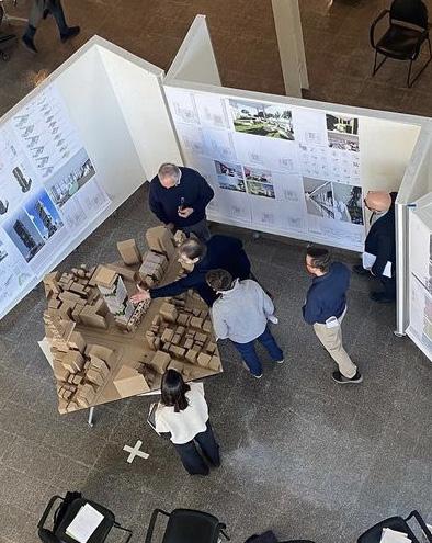
SPRING 2023 FINAL REVIEW AT THE CHICAGO ARCHITECTURE CENTER
CONTENTS

PEBBLES
POSTPARTUM CARE FACILITY
Healthcare / Hospitality
THE GENERATOR
BUSINESS INCUBATOR
Office / Research
AER-0 CENTER
ADAPTIVE REUSE
Research / Educational
FLOW
MIXED-USE HIGH RISE
Hotel / Condominium
03 CONTENTS
30 38
04 18
PEBBLES
Chicago, Illinois
Partner Project with Landscape Arch. Student
Professor Aneesha Dharwadker
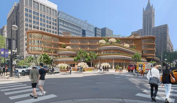
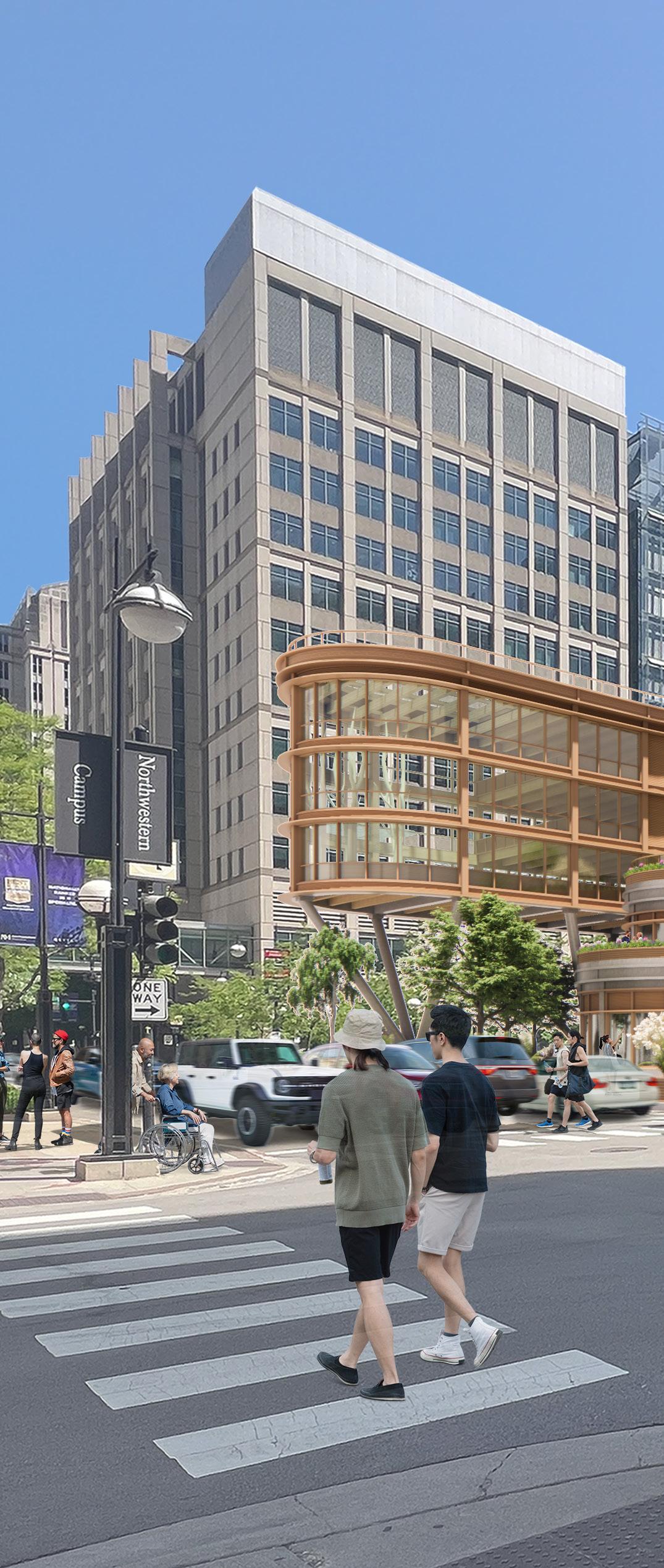
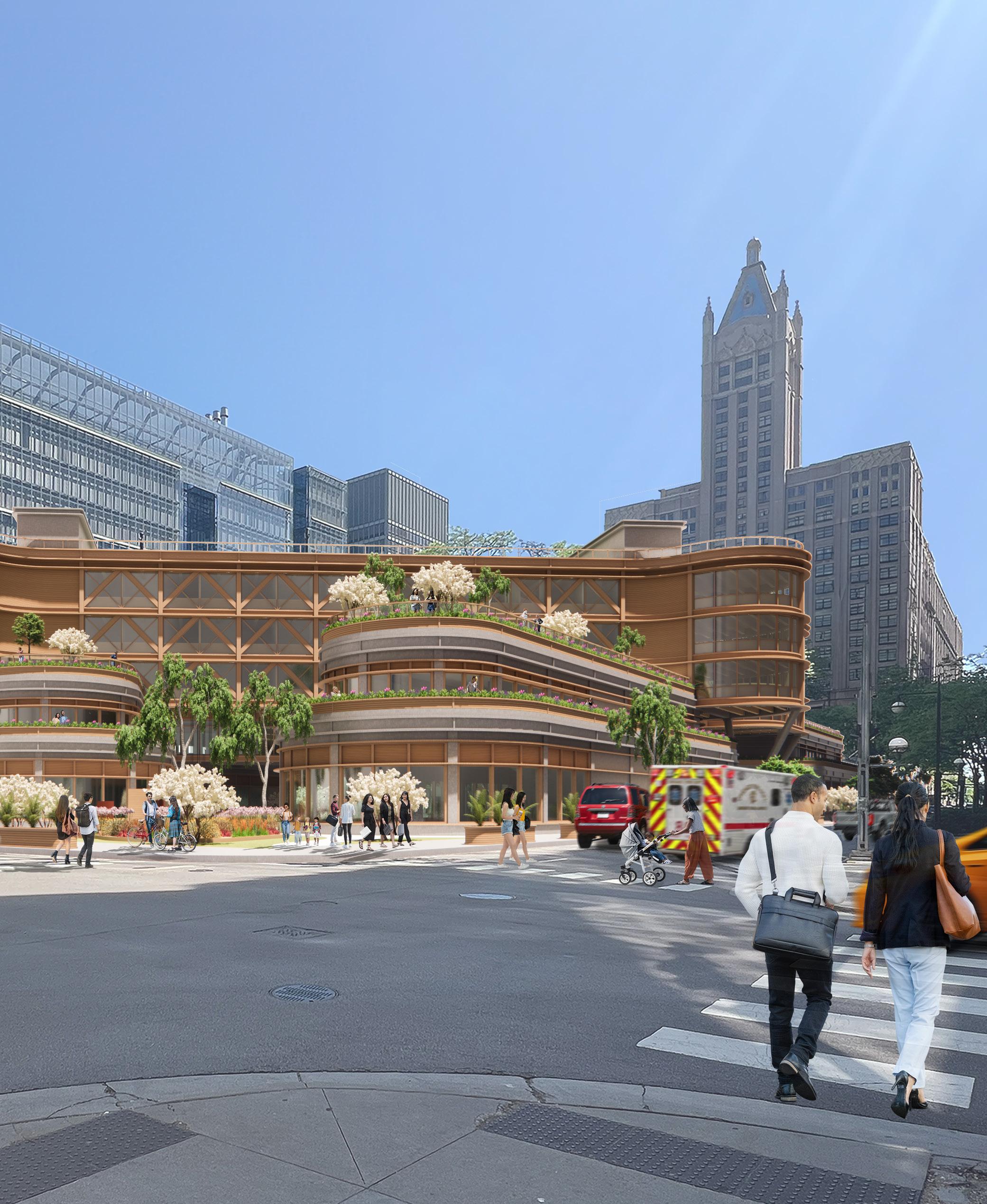
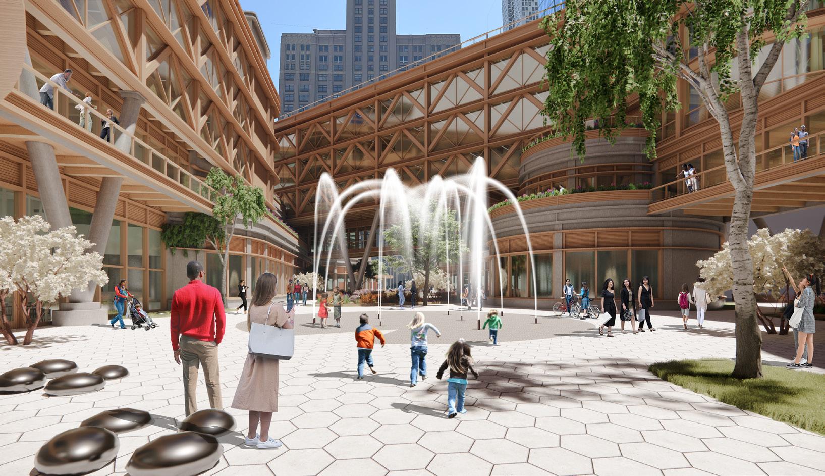
A postpartum care facility near the Northwestern Medicine Campus in Streeterville to challenge the status quo of postpregnancy care in U.S. healthcare.
In the United States, there is a lack of sufficient postpregnancy support as families transition to life with a newborn. This interdisciplinary studio aimed to design a Postpartum Care Facility that promoted healing, bonding, and support through thoughtful architectural and landscape design. It was an exercise in fusing the support and resources found in a medical setting with the comfort and amenities offered in a hotel setting. The building was envisioned as a sculptural element within a park, enhancing its therapeutic environment while maintaining site connections. The facility featured 54 guest rooms, care team stations, guest and staff amenities, and commercial spaces, to accommodate families during the critical first 6 to 8 weeks.
04 3RD YEAR GRAD
05 PEBBLES
VIEW FROM N. FAIRBANKS COURT & E. ERIE STREET

1.
Limited degree of pedestrian connections.
Terracing provided at multiple levels.
Opportunity for singly-loaded corridor oriented toward courtyard.
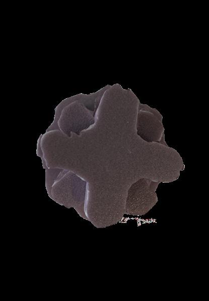
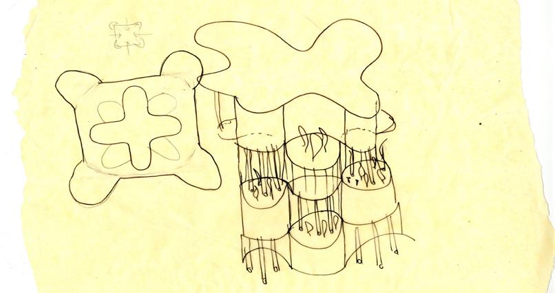
Curvilinear form softens the massing - Divine Feminine.
Consistent floor plans and core location with rotation.
Upper floors have more natural light exposure.
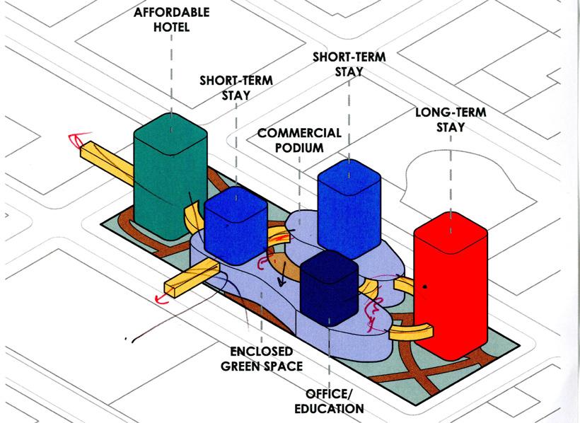
Separate towers for each primary use.
Central amenity podium connected through skybridges.
Architecture within an urban park.


More conscious of creating pedestrian connections.
Interior circulation can become inefficient depending on massing organization.
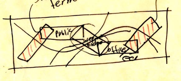
Guest wings float across park atop amenity podiums.
IDEAS
06 3RD YEAR GRAD
IDEA / CONCEPT Key
INITIAL
Takeaway(s)
JENGA
4. BRIDGE
3. VILLAGE
2. CLOVER
LURIE CHILDREN'S HOSPITAL & PRENTICE WOMEN'S HOSPITAL
THE MAGNIFICENT MILE
CONNECTION
NORTHWESTERN SCHOOL OF MEDICINE
LAKEFRONT TRAIL
OHIO STREET BEACH PARKING
LEVEL 1
EARLY FAMILY EDUCATION CENTER FAST CASUAL RESTAURANT
BABY STORE
COFFEE SHOP
CIRCULATION
PRAY ROOM
SALT CAVE CO-OP GROCERY STORE LOADING DOCK & STORAGE
CHILD CARE CENTER
CONSULTANT OFFICES FACILITY CHECK-IN
ADMIN OFFICES ENTRY ATRIUM
WOMEN’S WELLNESS CENTER FITNESS CENTER
MEN’S SAUNA
LEVEL 2
YOGA STUDIO PHYSICAL THERAPY
STAFF AMENITY SPACES
GUEST AMENITY SPACES
TERRARIUM
CARE TEAM STATION
GUEST AMENITY SPACES
TERRARIUM
GUEST ROOMS (54)
SERVICE & LOADING DOCK FACILITY DINING
BRIDGE
LEVELS 3 - 5
LEGEND:
FINAL SITE STRATEGY PROGRAM DIAGRAM
GUEST AMENITY SPACES STAFF BREAK ROOM
SOCIAL BAR
STAFF AMENITY SPACES
PUBLIC GUEST STAFF SERVICE 07 PEBBLES
ROOF
EL. 87’ - 4”
LEVEL 5 - GUEST ROOMS
EL. 72’ - 10”
LEVEL 4 - GUEST ROOMS
EL. 58’ - 4”
LEVEL 3 - GUEST ROOMS
EL. 43’ - 10”
RAISED FLOOR SYSTEM
2’ - 10”
LEVEL 2 - GUEST CHECK-IN
EL. 23’ - 0”
ENTRY ATRIUM
EL. 0’ - 0”
08 3RD YEAR GRAD
ELEVATOR PENTHOUSES
LEVEL 3 - TERRARIUM
- 10”
LEVEL 2 - SKY-BRIDGE
NORTH-SOUTH PERSPECTIVE
EL. 23’ - 0” EL. 43’09 PEBBLES
EL. 100’ - 6”
SECTION


E.
N.
HURON STREET
E.
ERIE STREET
FAIRBANK COURT
SALT CAVE
FAST CAUSAL RESTAURANT SEMINAR ROOM SEMINAR ROOM SEMINAR ROOM SEMINAR ROOM LECTURE HALL/ MOVIE THEATER ATRIUM FACILITY DINING CENTER FACILITY SERVICE AREA SEMINAR ROOM SEMINAR ROOM
COFFEE
SHOP
CO-OP GROCERY STORE LOADING DOCK
NAP
LUNCH-
STAFF GUEST AMENITY TERRARIUM STAFF STAFF STOR. STOR. TERRARIUM GUEST AMENITY GUEST ROOM CARE TEAM STATION 10 3RD YEAR GRAD LEVEL 3 FLOOR PLAN: GUEST WINGS LEVEL 1 FLOOR PLAN: COMMERCIAL SPACES & FACILITY ENTRY
BABY STORE
PLAYROOM
ROOM
ROOM
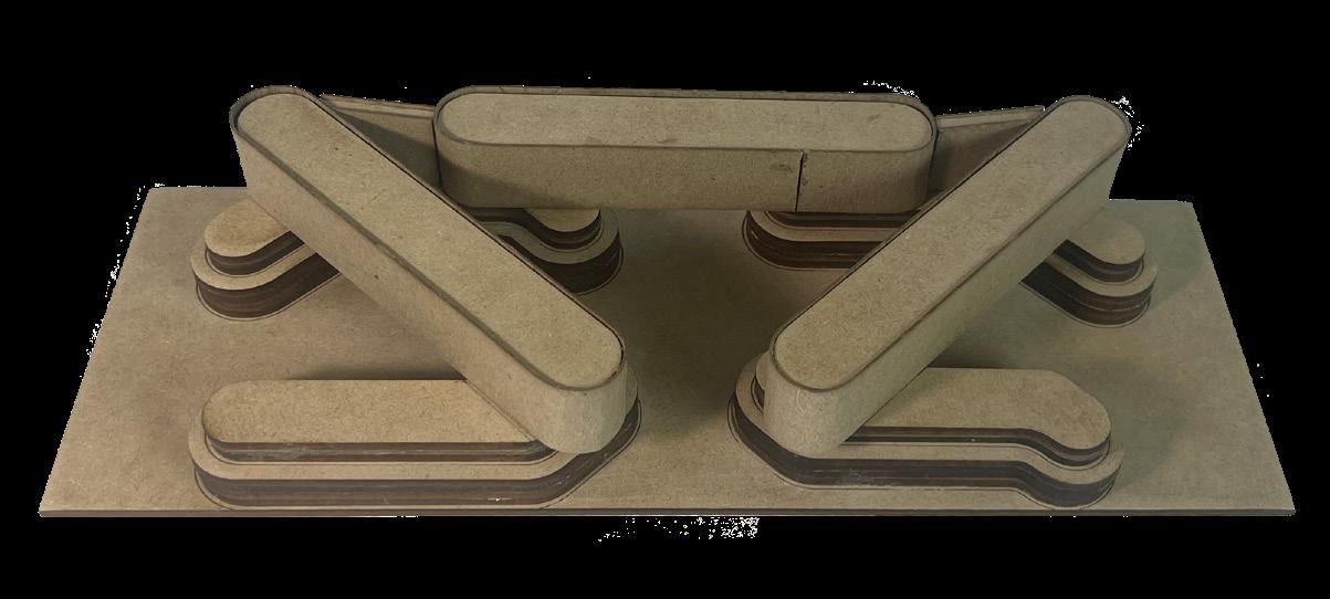
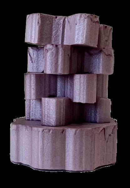
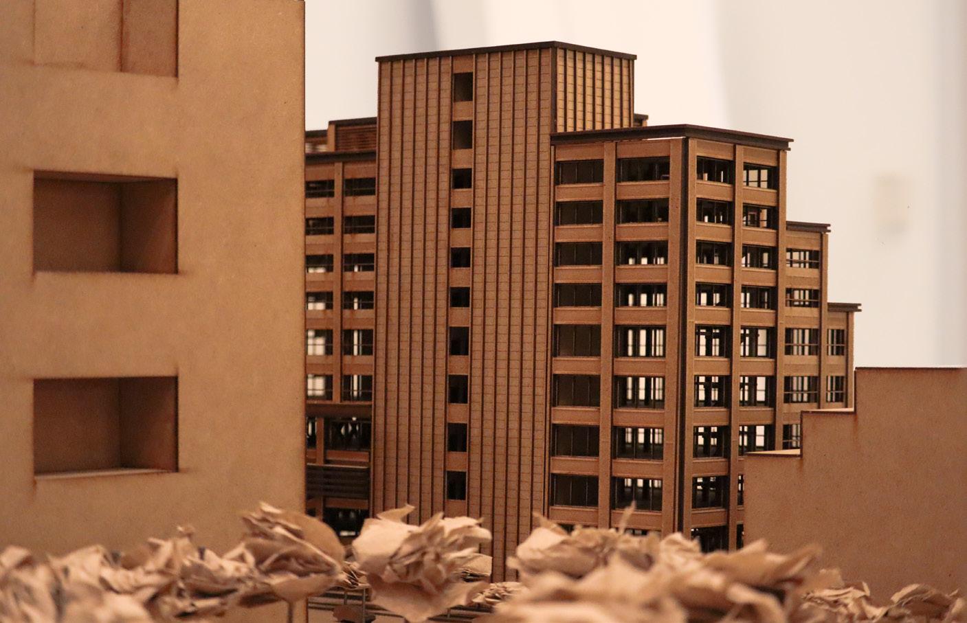
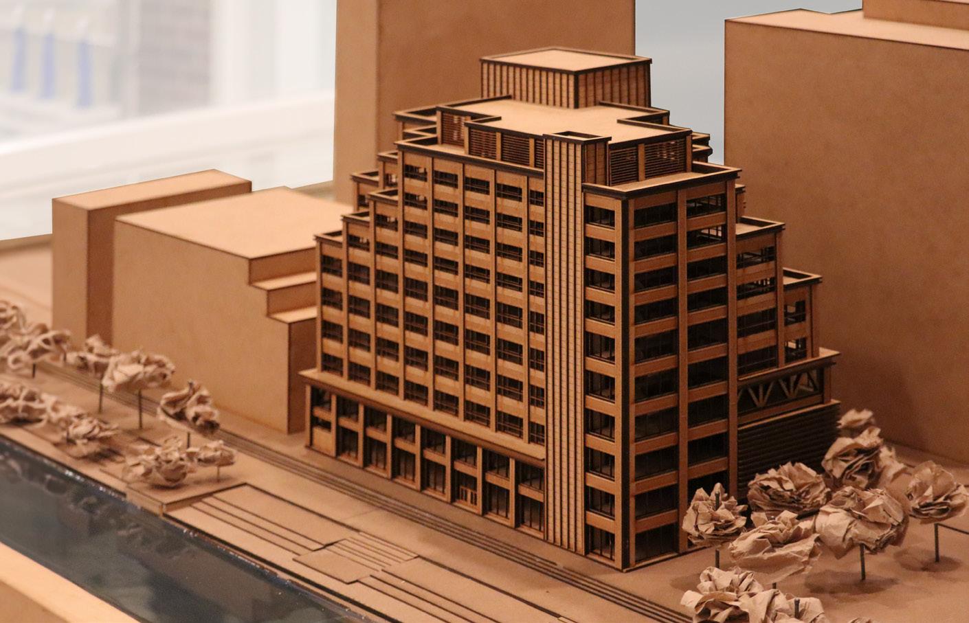
PHYSICAL MODEL: MIDTERM MASSING
PHYSICAL MODEL: FINAL MASSING


PHYSICAL MODEL: FINAL MASSING WITHIN SITE CONTEXT
N.
FACILITY DINING CENTER STAFF GUEST AMENITY 11 PEBBLES
McCLURG COURT
0 60 20 140 FT
COURTYARD
To create a sculptural element in the park, the four podiums were envisioned as pebbles, with guest wings bridging across like sticks. This concept influenced the structural and facade materials: reinforced concrete for the podiums and mass-timber for the guest wings. Structural elements were prominently featured on the facade to provide a consistent rhythm, breakdown scale, and, in the case of the inclined columns, to enhance the visual connection with the ground plane. Proportional curvilinear forms with wood solar shades, mullions, and spandrel panels served as unifying elements.
12 3RD YEAR GRAD
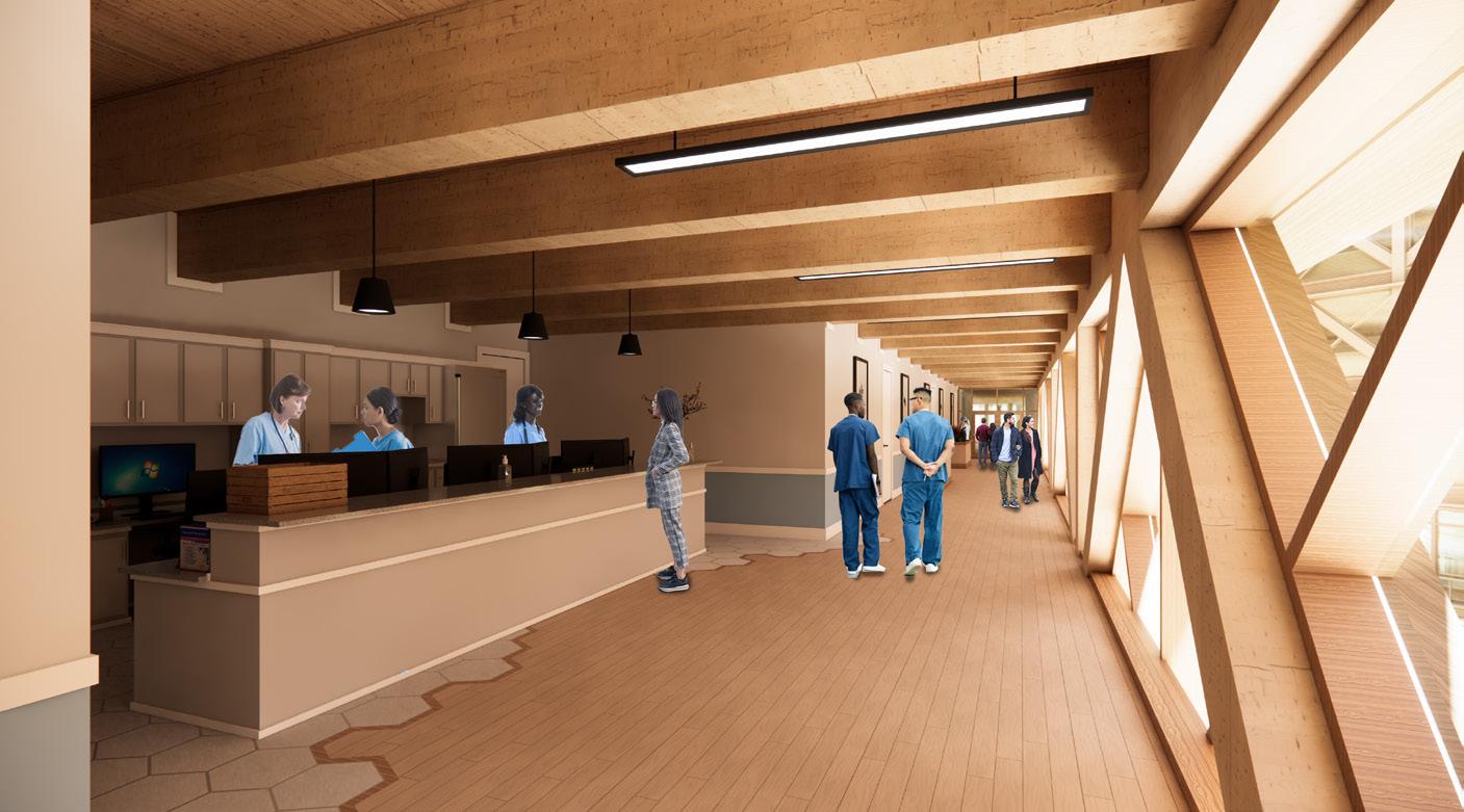
GUEST WING: TYPICAL CORRIDOR
WALK-IN SHOWER + BATHTUB
WASHER/ DRYER DESK SLEEPER SOFA BATHROOM KITCHENETTE LIVING
MUD
NURSERY STORAGE QUEEN SIZE BED DISHWASHER REFRIGERATOR MICROWAVE STORAGE BATHROOM BREAKROOM ON-CALL
WORK STATION 13 PEBBLES
GUEST ROOM CARE TEAM STATION
ROOM
ROOM BEDROOM
ROOM
TYPICAL CARE TEAM STATION 0 4 12 FT
QUEEN SIZE BED
BEDROOM NURSERY
LIVING ROOM
KITCHENETTE
BATHROOM
MUD ROOM
WALK-IN SHOWER + BATHTUB GUEST
WASHER/ DRYER
SLEEPER SOFA
ROOM
DESK
STORAGE
DISHWASHER REFRIGERATOR MICROWAVE STORAGE ON-CALL 14 3RD YEAR GRAD TYPICAL GUEST ROOM 0 4 12 FT
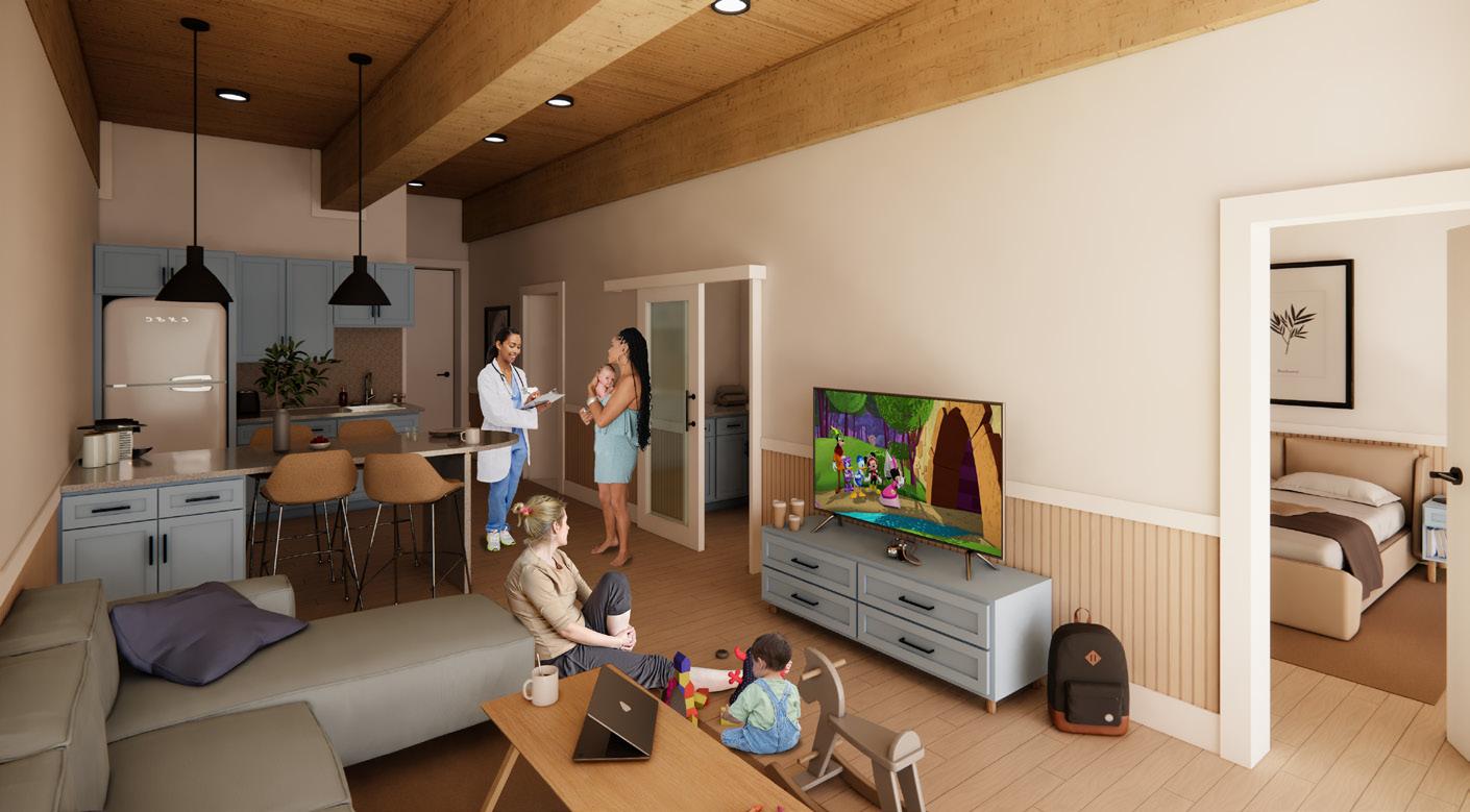
GUEST ROOM: LIVING AREA
The Guest Rooms were designed to blend the comfort and amenities of a hotel suite with reimagined, hospital-like support spaces. These latter set of spaces incorporated an expanded, subdivided bathroom, in-unit laundry, and a nursery accessible from both the living area and bedroom .
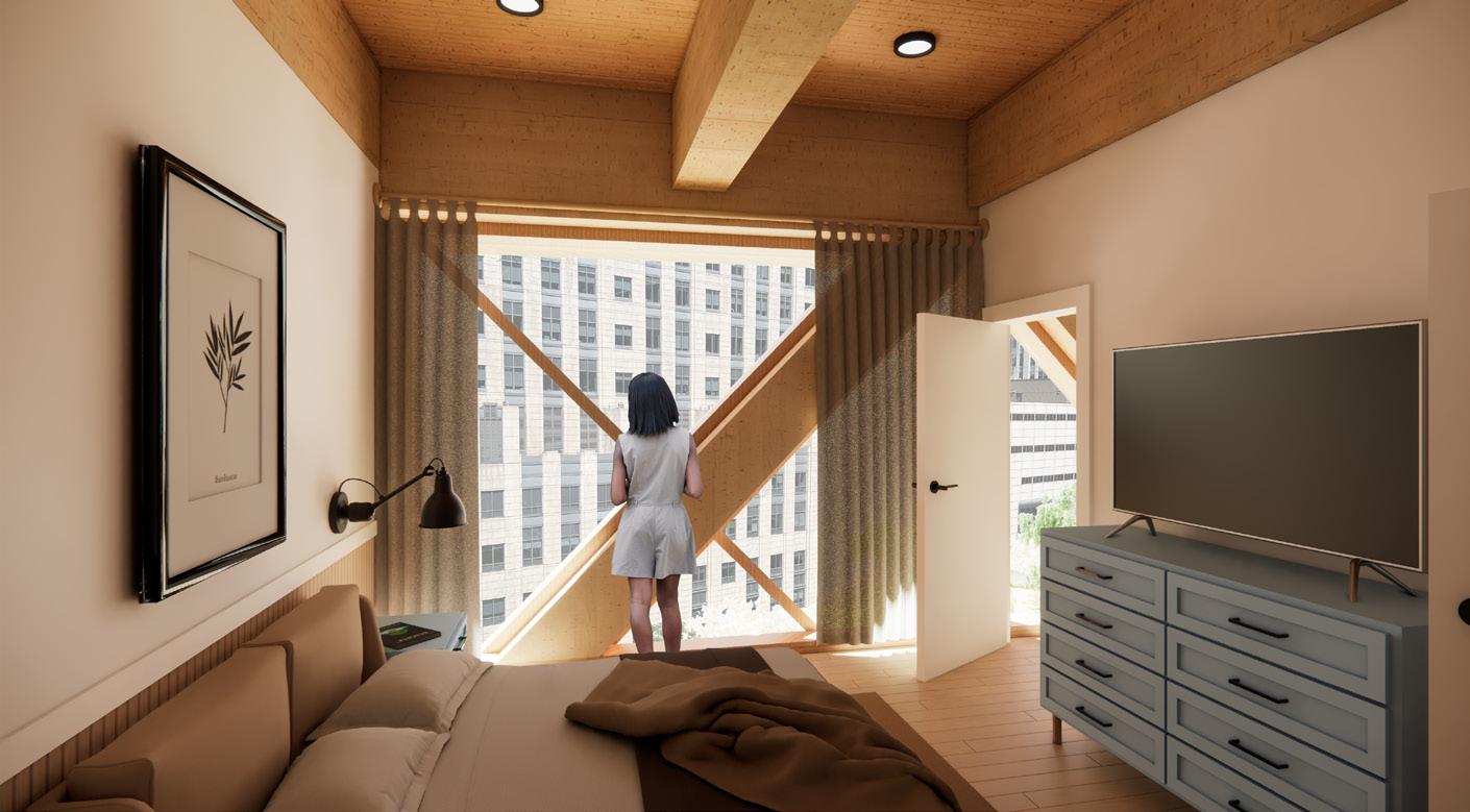
GUEST ROOM: BEDROOM
The exposed mass-timber structure along the exterior wall and ceiling plane in tandem with the millwork and soft blue furniture accents cultivated a warm, soothing atmosphere. The truss system’s fenestration layout mimicked tree branches, strengthening the concept of the facility floating across the park below.
15 PEBBLES

16 3RD YEAR GRAD
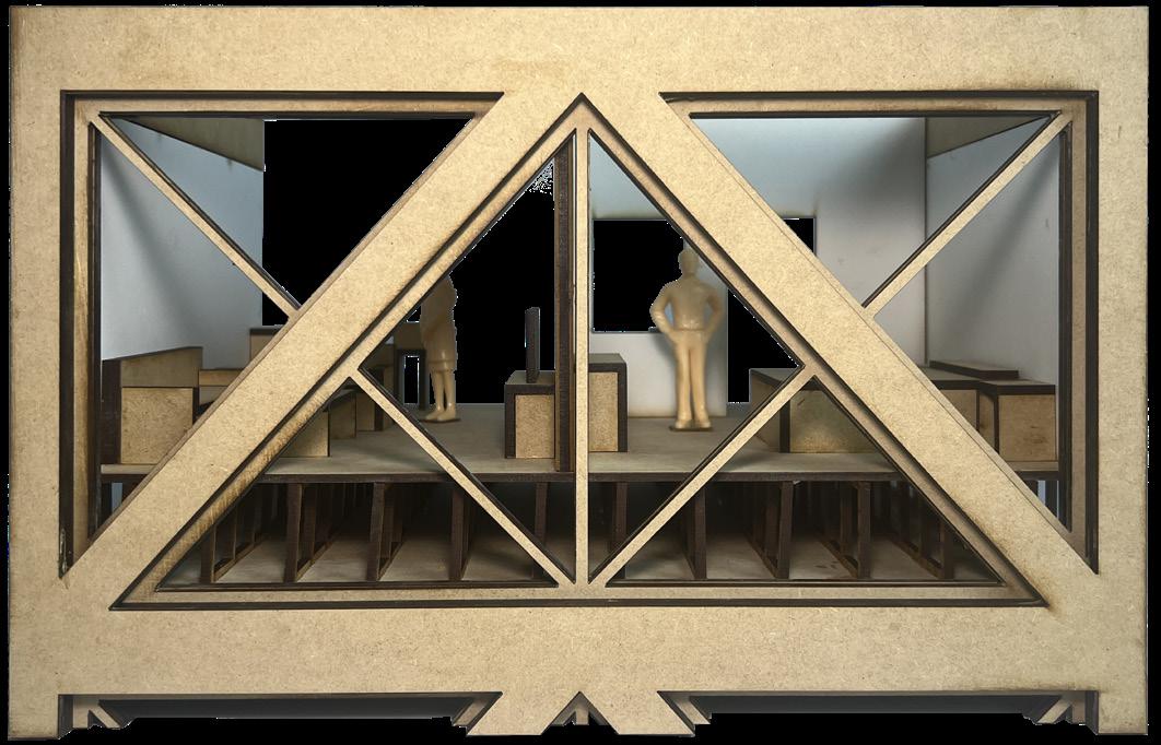
PHYSICAL MODEL: FACADE SECTION - EXTERIOR


17 PEBBLES
PHYSICAL MODEL: FACADE SECTION - INTERIOR
ELEVATION
SOUTH
THE GENERATOR
Chicago, Illinois Partner Project
Professor Tom Leslie
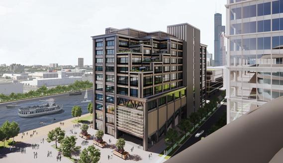
An incubator and accelerator located at the 78 Development to align with the mission of the new Discovery Partners Institute (DPI)
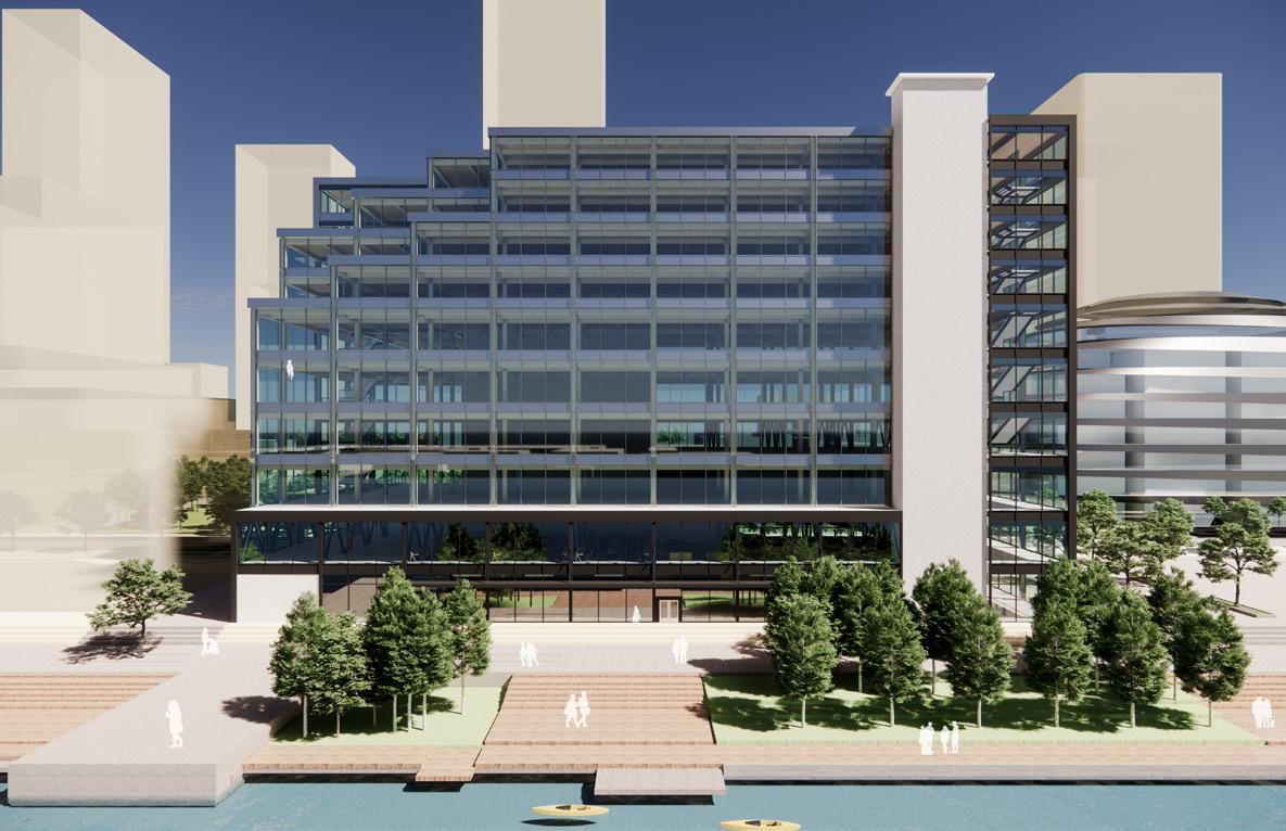
The challenge was to design a building to serve entrepreneurs and the public while complementing the new DPI building. The concept sought to foster collaboration through a central circulation spine on each level that connected two stair atriums. These “Stairiums” would feature informal meeting spaces to encourage spontaneous discussions. Three design themes: structural expressionism, spatial flexibility, and innovation within Chicago’s architectural style, were integrated into the building’s aesthetic. This multifaceted approach cultivated a bold design through structure that enhanced the architecture, new vernaculars synthesized with historical elements, and spaces that seamlessly interact with the 78 Development and beyond.
18 2ND YEAR GRAD
19 THE GENERATOR VIEW FROM DPI
PROGRAM
Ensure efficient access to labs
LATERAL SYSTEM
Encloses the vertical circulation
STEP BACK
Yield to the human scale
STEEL PODIUM
Opens the ground plane
RELINQUISH
Correspond to DPI’s height
CONCEPT DIAGRAMS
MASS-TIMBER
Promotes health and wellbeing
STRUCTURAL DIAGRAMS
20 2ND YEAR GRAD

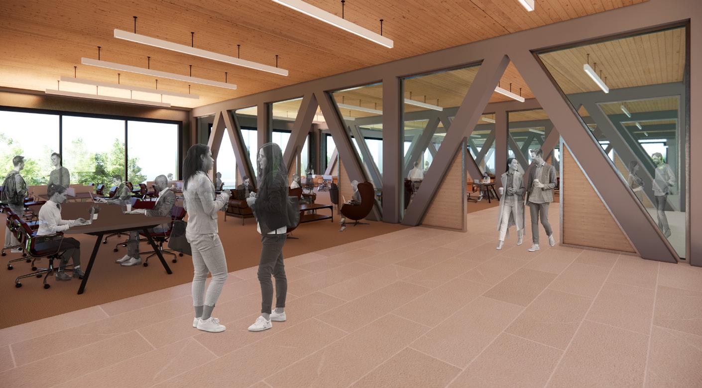
LEVEL 5: NORTH STAIRIUM
The concept aimed to enhance collaboration by establishing a central circulation spine on each level, linking two stair atriums, or “Stairiums.” These Stairiums were positioned at the building’s north and south ends. To enhance collaboration through circulation, each level’s social and meeting spaces were located at these nodes. The Stairiums were envisioned as the principal means of vertical circulation, fostering movement between open-office and lab levels. This dual function of circulation and collaboration positioned the Stairiums as vibrant social hubs on and between levels.
21 THE GENERATOR
MECHANICAL LEVEL
LEVEL 11
OPEN OFFICE (INCUBATOR)
LEVEL 10
OPEN OFFICE (INCUBATOR) LEVEL 9
OPEN OFFICE (INCUBATOR) LEVEL 8
OPEN OFFICE (INCUBATOR) LEVEL 7
WET LABS LEVEL 6
MAKER LABS / WET LABS
LEVEL 5
MAKER LABS
LEVEL 4
AUDITORIUM / OPEN OFFICE
LEVEL 3
OPEN OFFICE (ACCELERATOR )
LEVEL 2
FOOD HALL
LEVEL 1
SOUTH STAIRIUM
LEVELS 4 - 10
22 2ND YEAR GRAD
NORTH STAIRIUM LEVELS 2 - 10
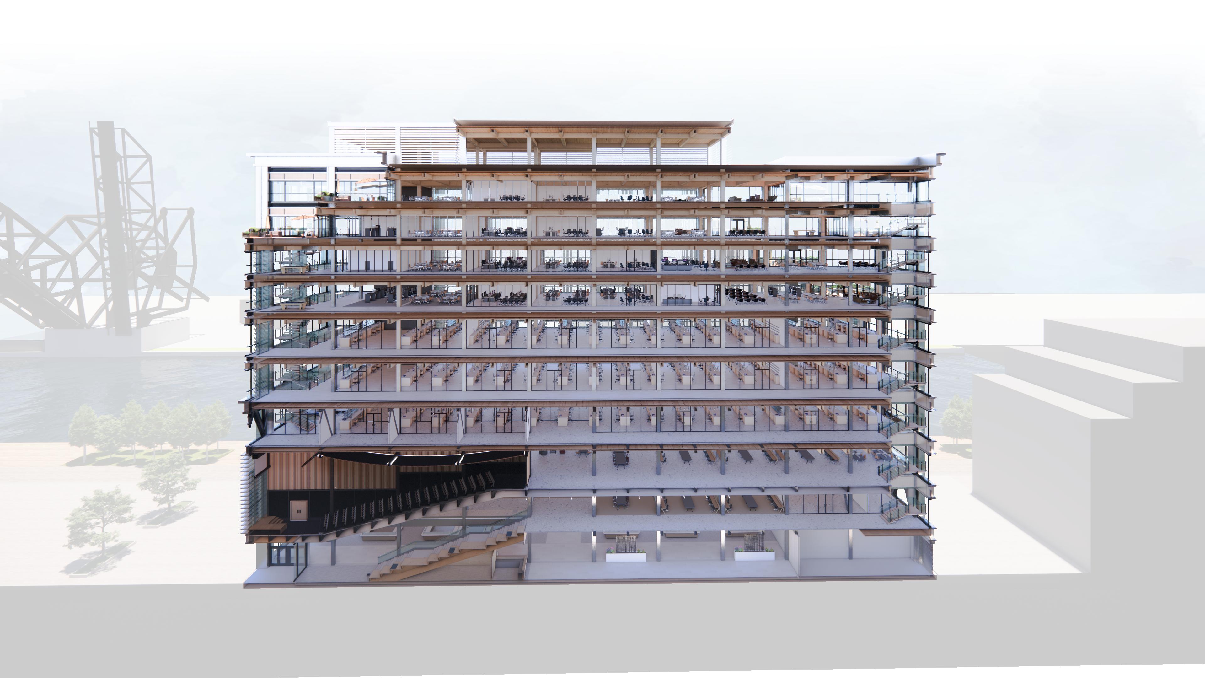
NORTH-SOUTH PERSPECTIVE SECTION
23 THE GENERATOR


PITCH SPACE LEARNING STAIRS ADMIN KITCHEN SERVICES STORAGE 24 2ND YEAR GRAD LEVEL 1 FLOOR PLAN: FOOD HALL & LEARNING STAIR LEVEL 2 FLOOR PLAN: OPEN OFFICE (ACCELERATOR) Men’s BR Women’s BR Men’s BR Women’s BR 0 20 10 60 FT
The trusses on Levels 2 and 4 integrated with the architecture by dividing spaces and demarcating pathways while efficiently transferring column loads. This multifaceted design facilitated the use of masstimber above, minimized columns below, and demonstrated innovative architectural integration.

The first level played a crucial role as a seamless link between site features and building’s use. Long-span trusses were employed to minimize the number of columns. The southeast side was anchored by the pitch space and the food hall was positioned along the west half to capitalize on the future Riverwalk.
25 THE GENERATOR
LEVEL 1: FOOD HALL
LEVEL 2: OPEN OFFICE (ACCELERATOR)
EXTERIOR
CURTAIN
WALL
AIR VENT
SPANDRELS
LOUVERS WOOD
2’ CATWALK
INTERIOR CURTAIN WALL

DOUBLE SKIN FACADE AXON SECTION
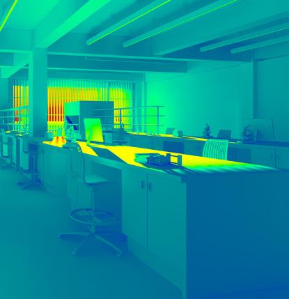
The facade design posed a significant challenge, requiring a balance of natural light, exterior views, and solar heat control. The east and west elevations, with expansive glass walls for lab and office spaces, required effective light control for a suitable work environment. A double skin facade with movable internal fins was chosen to manage natural light penetration in each bay. This facade featured an exterior curtain wall with vents, a two-foot maintenance catwalk, fin assembly, and an internal curtain wall. In winter, the space could be sealed for natural heating, while in summer, vents allowed for natural cooling. The metal grates provided maintenance access and air movement. This solution preserved the strong Chicago-inspired facade while effectively managing solar heat and glare for occupants.


13’9” 10’9” 13’11” 16’11” OPEN OFFICE
WEB LAB
18’ - 6” 28’ - 8” 15’ - 0” 26 2ND YEAR GRAD
WET LAB SPACE - FINS CLOSED
WET LAB SPACE - FINS OPEN
1. MIDTERM REVIEW
2. DESIGN DEVELOPMENT
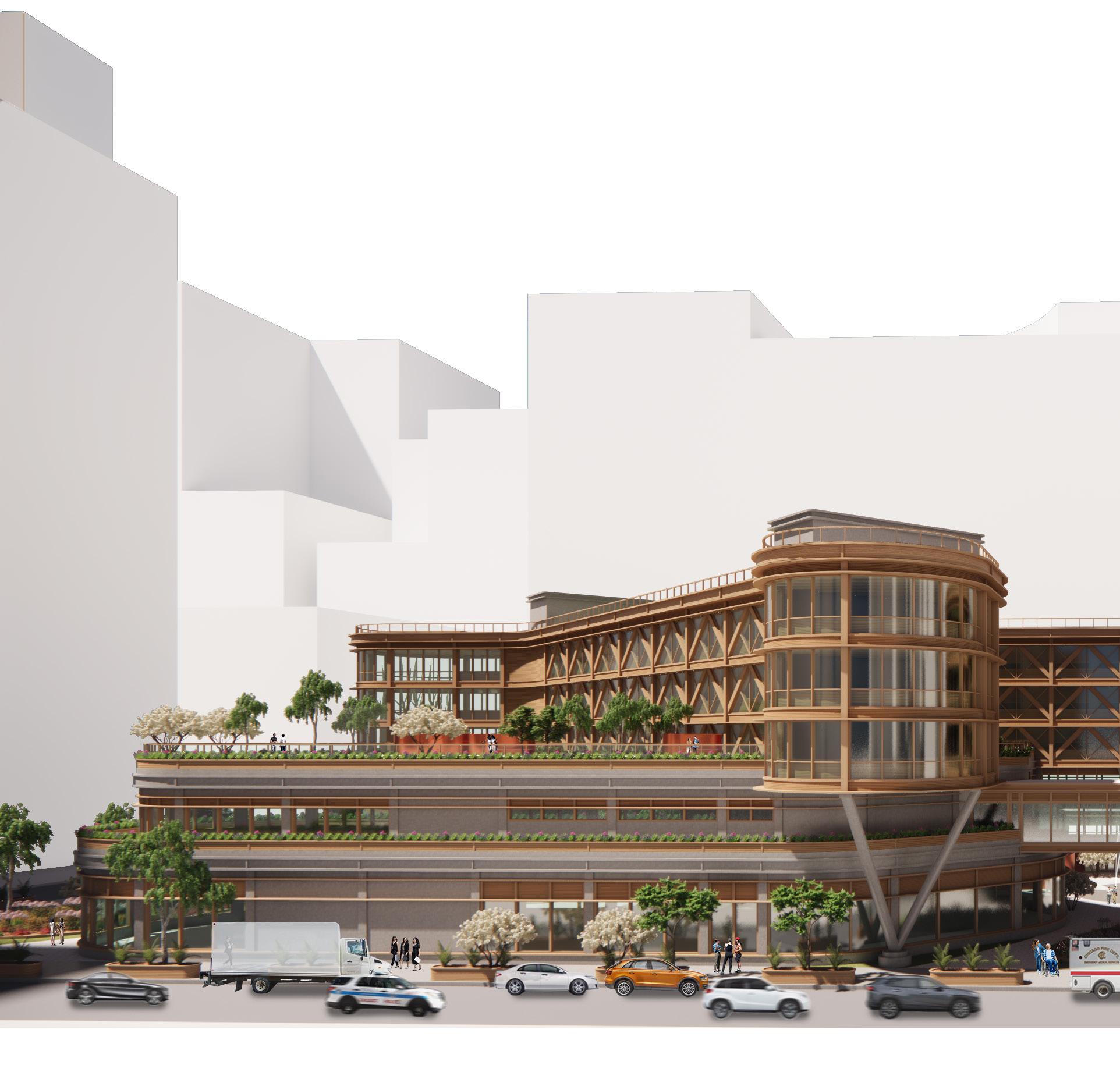
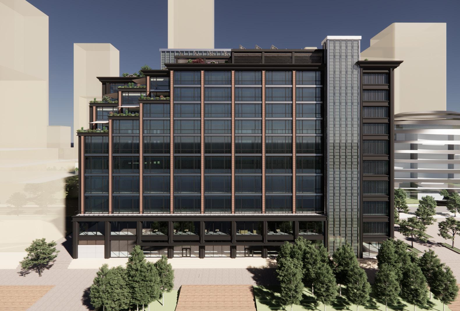
WEST ELEVATION

The building’s exterior sought to reflect Chicago architecture through incorporating historic elements like the Chicago window and new vernaculars with mass-timber. An emphasis was placed on expressing the structural materials to complement the structural expression on the interior. However, there was the intrinsic need for the facade to maintain cohesion. Therefore, the first step was establishing common elements like profile shapes, proportions, and curtain wall unit design. After a number of iterations, the structural material of steel, mass-timber, or concrete was framed and detailed with aluminum with matte gray and black finishes.
Pat WEST ELEVATION Michelle & Pat 30 27 THE GENERATOR
FACADE ITERATIONS
0 20 60 120 FT

PHYSICAL MODEL: SOUTHEAST BIRDSEYE VIEW
28 2ND YEAR GRAD
PHYSICAL MODEL: WELLS STREET ELEVATION
PHYSICAL MODEL: RIVERWALK ELEVATION
29 THE GENERATOR
AER-0 CENTER
Rantoul, Illinois Team Project Professor Scott Murray
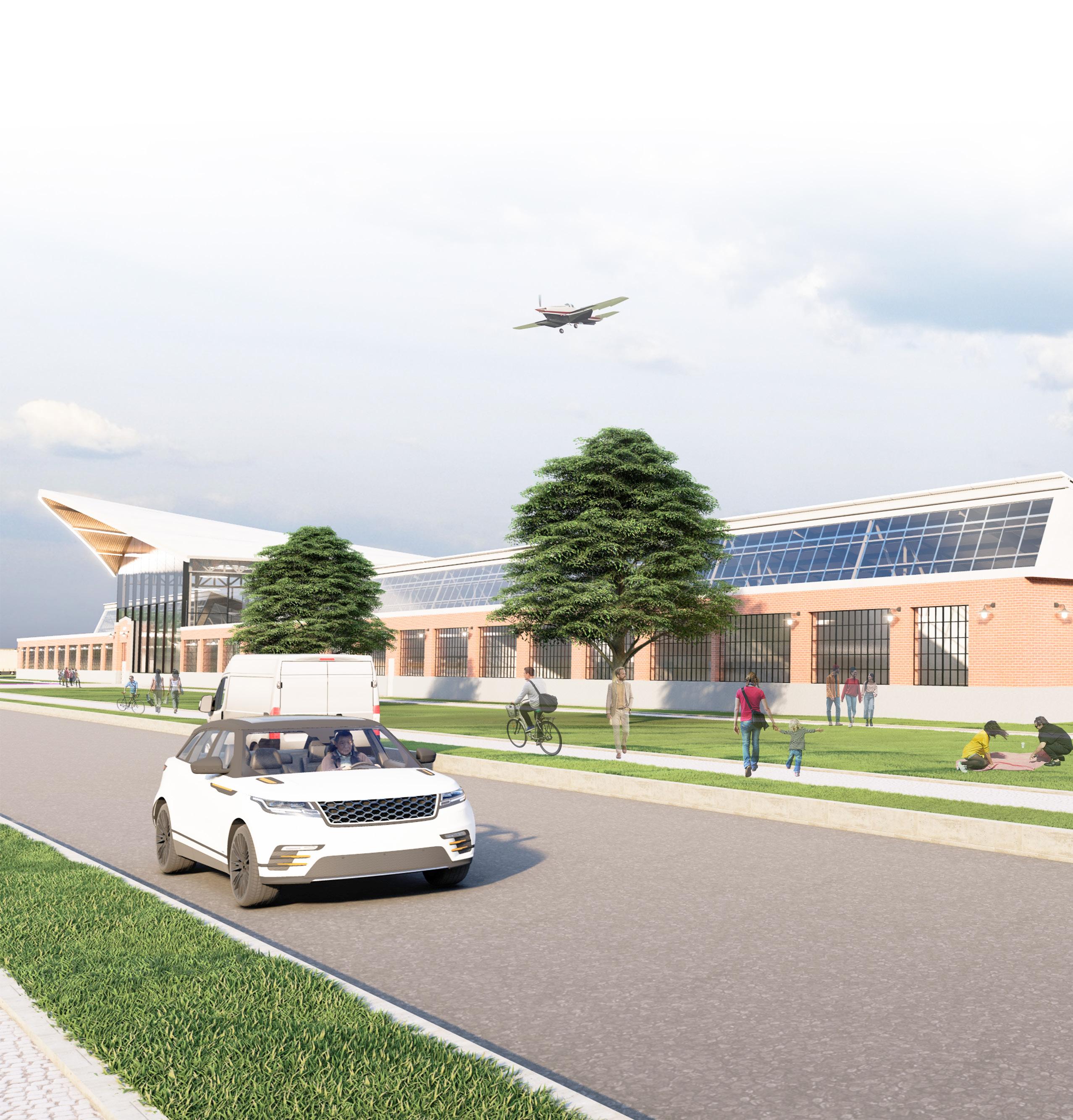
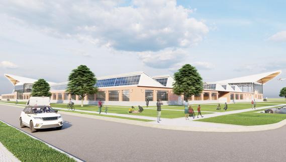
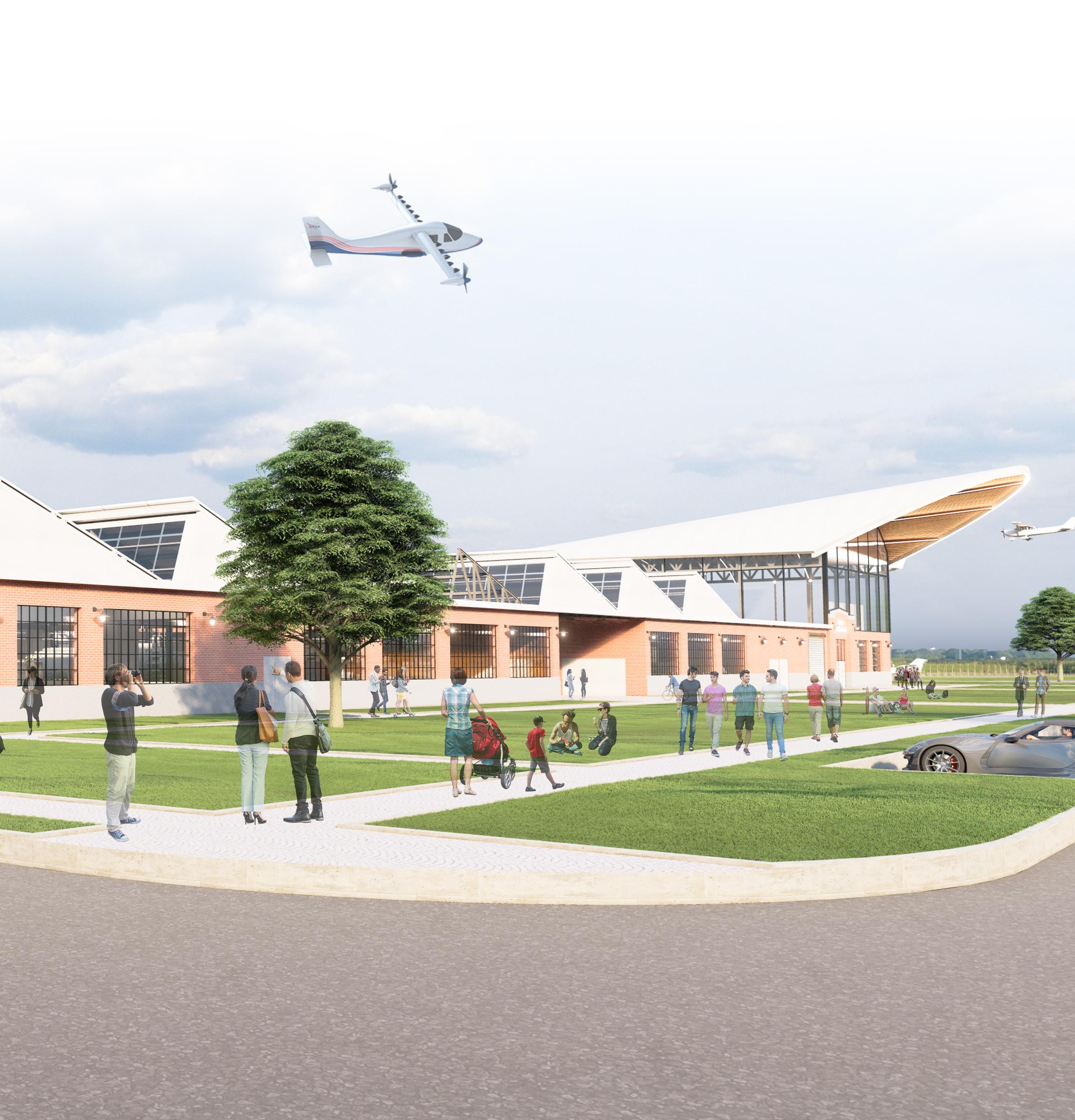
An adaptive reuse proposal that transformed a hanger into the Center for Aerospace and Electrical Engineering Research in Zero Emission Aircraft (AER-0).
The challenge was to re-imagine a World War 2 era hanger that generated community interest and emphasized sustainability. The concept was transforming a 20th century hangar to fulfill the 21st century’s ambition for netzero emissions in both buildings and aircraft. The design proposal would provide a research facility for the University of Illinois’s ongoing research into electric aircraft.
30 1ST YEAR GRAD
31 AER-0 CENTER
VIEW
NORTHWEST CORNER
CollaborativeSpaces Cafe Admin ComponentAssembly TestingComponent BatteryStorageComponentStorage Service InteractiveLearningCenterAircraftAssemblyAircraftStorage ALIGNED TO VIEWS OF THE EXISTING RUNWAY ALIGNED TO THE EXISTING PARKING LOT Component Delivery Component Storage Component Assembly Component Testing Aircraft Assembly Aircraft Storage to await Testing (Hanger) Battery Storage Research Interactive-Learning 32 1ST YEAR GRAD 3D PROGRAM DIAGRAM AIRCRAFT RESEARCH STEPS
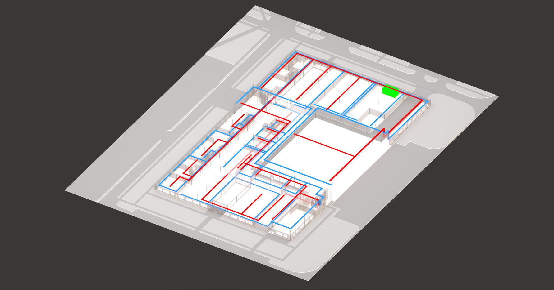
LEVEL 2 FLOOR PLAN: INTERACTIVE LEARNING CENTER
LEVEL 1 FLOOR PLAN: RESEARCH & DEVELOPMENT
DN DN B C D E F G H I J K A 1 2 3 4 5 6 7 8 9 10 11 12 13 14 16 17 15 UP UP B C D E F G H I J K A 1 2 3 4 5 6 7 8 9 10 11 12 13 14 16 17 20' - 0 1/2" 40' - 0" 40' - 0" 40' - 0" 40' - 0" 40' - 0" 40' - 0" 40' - 0" 40' - 0" 40' - 0" 40' - 0" 40' - 0" 40' - 0" 40' - 0" 40' - 0" 20' - 0 1/2" 20' 0 1/2" 40' 0" 40' 0" 40' 0" 40' 0" 40'0" 40' 0" 40' 0" 40' 0" 20' 0 1/2" 15 33 AER-0 CENTER
0 40 120 FT
AXONOMETRIC FLOOR PLANS
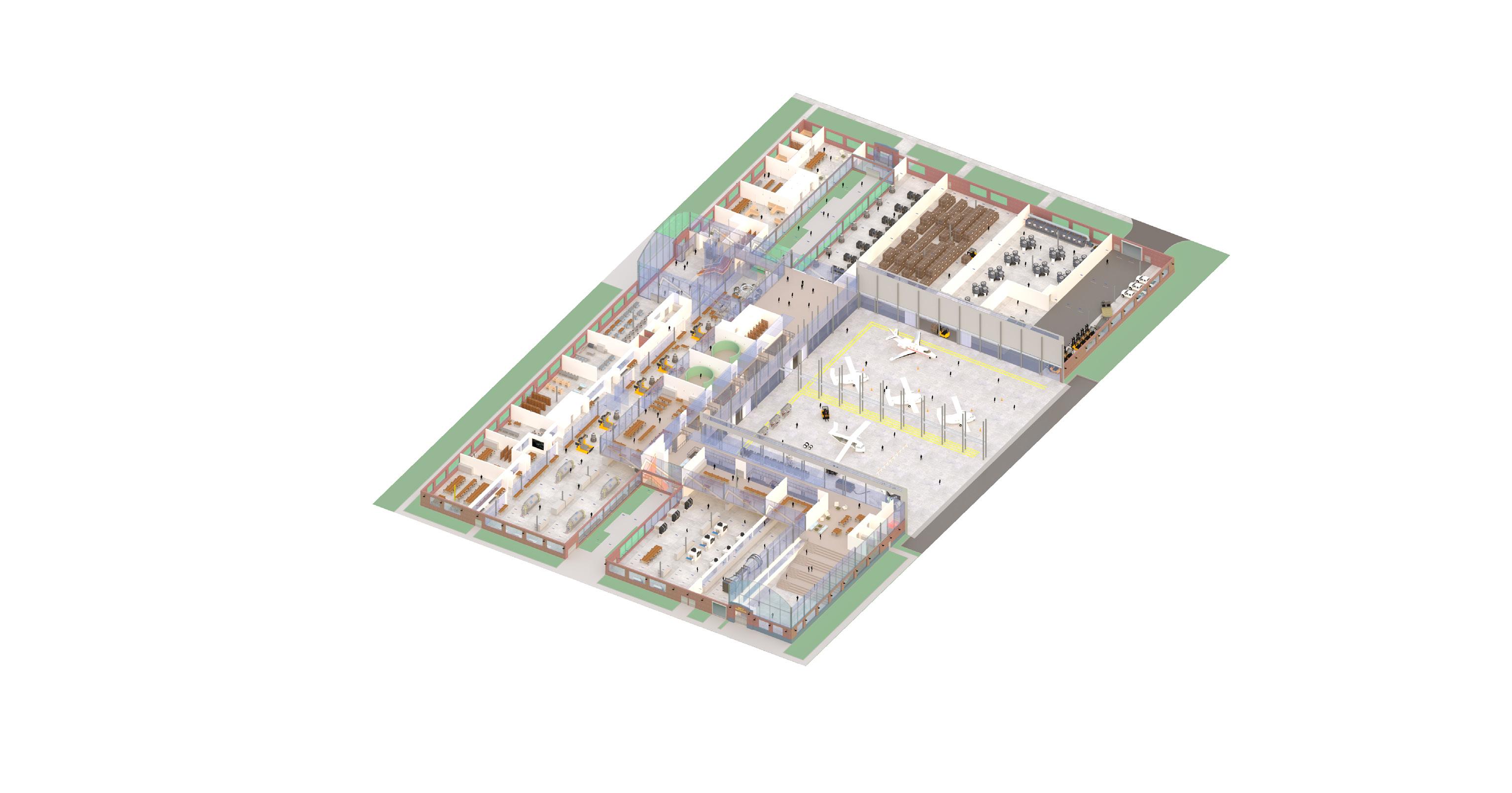
A critical component of the research program was creating spaces for public observation and education without interference. This was achieved by retaining the distinctive sawtooth roof and brick masonry while adding a second level mimicking aircraft wings. The first level focused on research and development, while the second level hosted the Interactive Learning Center with flight simulators, immersive workshops, and an auditorium. The second level’s adjacency to the high bay allowed framed views into component testing and assembly spaces below and panoramic views of the aircraft assembly and parking hangers.
34 1ST YEAR GRAD
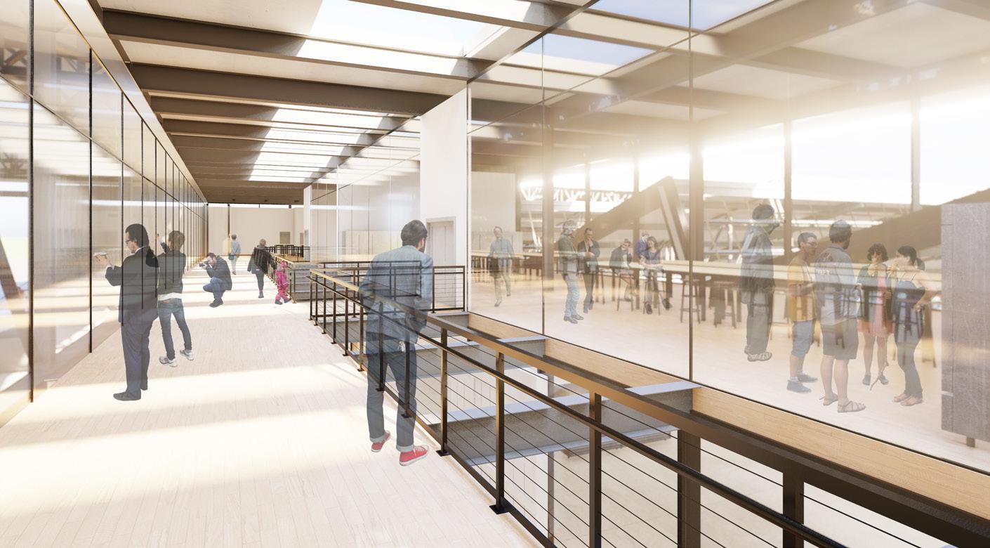
2ND LEVEL CORRIDOR

1ST LEVEL LOGISTICS PATH
The second level’s main corridor was strategically positioned above the first level’s research and logistics path. Initially conceived to enhance natural light penetration, it evolved to showcase the robust logistics required in the research and development process. Furthermore, unique views emerged at the abutment of the sawtooth roof and the second level’s exterior glass wall. These intersections developed into “windows” for Interactive Learning Center visitors to observe each stage of the process below.
35 AER-0 CENTER
Typical Column Size: W10 x 49
Typical Beam Size: WF24 x 40
Load-Bearing Masonry Walls
Saw-Tooth Roof Structure:
1. Purlins - 10” Deep Steel Channels
2. Center Beam - 18” Deep Wide Flange Center
3. Sawtooth Truss - Built-up Steel Angles
Highbay Roof Structure:
1. Purlins - W6 x 15
2. Truss - Built-up Steel Angles @ 20’ o.c.
3. X-Bracing - Built-up Steel Angles along perimeter
4. Center Girder Truss - Built-up Steel Angles
Winged-Roof Structure:
1. Purlins - W6 x 15

2. Truss - Built-up Steel Angles @ 20’ o.c.
3. Girder Truss - Built-up Steel Angles
STRUCTURAL DIAGRAM
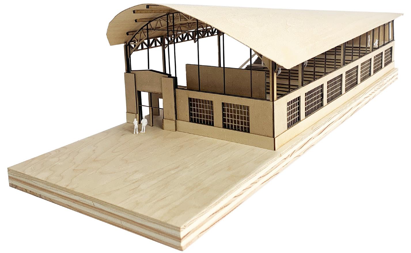
PHYSICAL MODEL: AUDITORIUM - EXTERIOR
36 1ST YEAR GRAD
NEW - 2nd Level Roof R-Value = 31
Existing - HighBay Roof Upgraded R-Value = 31
Existing - Sawtooth Glass Triple Glazed, Low E Glass Upgraded U-Value = 0.25 NEW - Skylights
Existing - Skylights
- Solar Panels
Sawtooth Roof = 30 degrees
Roof = 10 degrees

BUILDING ENVELOPE DIAGRAM
Glazed, Low E Glass Upgraded U-Value = 0.25
Existing - HighBay Walls Upgraded R-Value = 25
Existing - LowBay Roof Upgraded R-Value = 31 NEW - Curtain Walls Triple Glazed, Low E Glass U-Value = 0.25
Existing - LowBay Masonry Walls Upgraded R-Value = 25
Existing - 1st Level Windows Triple Glazed, Low E Glass Upgraded U-Value =0.25
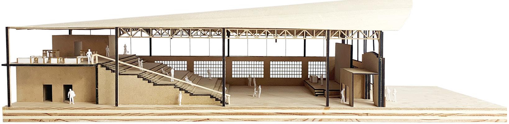
PHYSICAL MODEL: AUDITORIUM - INTERIOR
The two model photos in conjunction with the building diagrams above capture how the new “Aircraft Wings” are integrated with the existing building. The Entry Atrium and the Auditorium serve as the start and end points respectively of the Interactive Learning Center. The Auditorium was envisioned as a multipurpose space particularity through the inclusion of a learning stair. This would allow the space to quickly transition from a informal research and collaboration area to large gathering space for presentations. Its location at the southwest corner directed views toward the runway as the research into electric aircraft takes flight.
Triple Glazed, Low E Glass U-Value = 0.25
Triple
NEW
37 AER-0 CENTER
Highbay
FLOW
Chicago, Illinois
Team Project
Professor Paul Armstrong
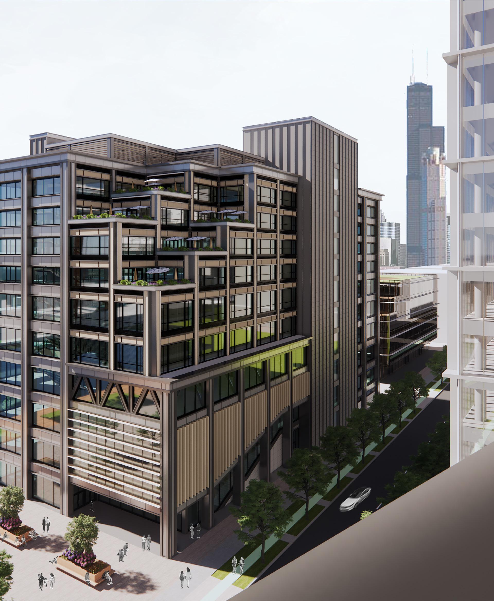
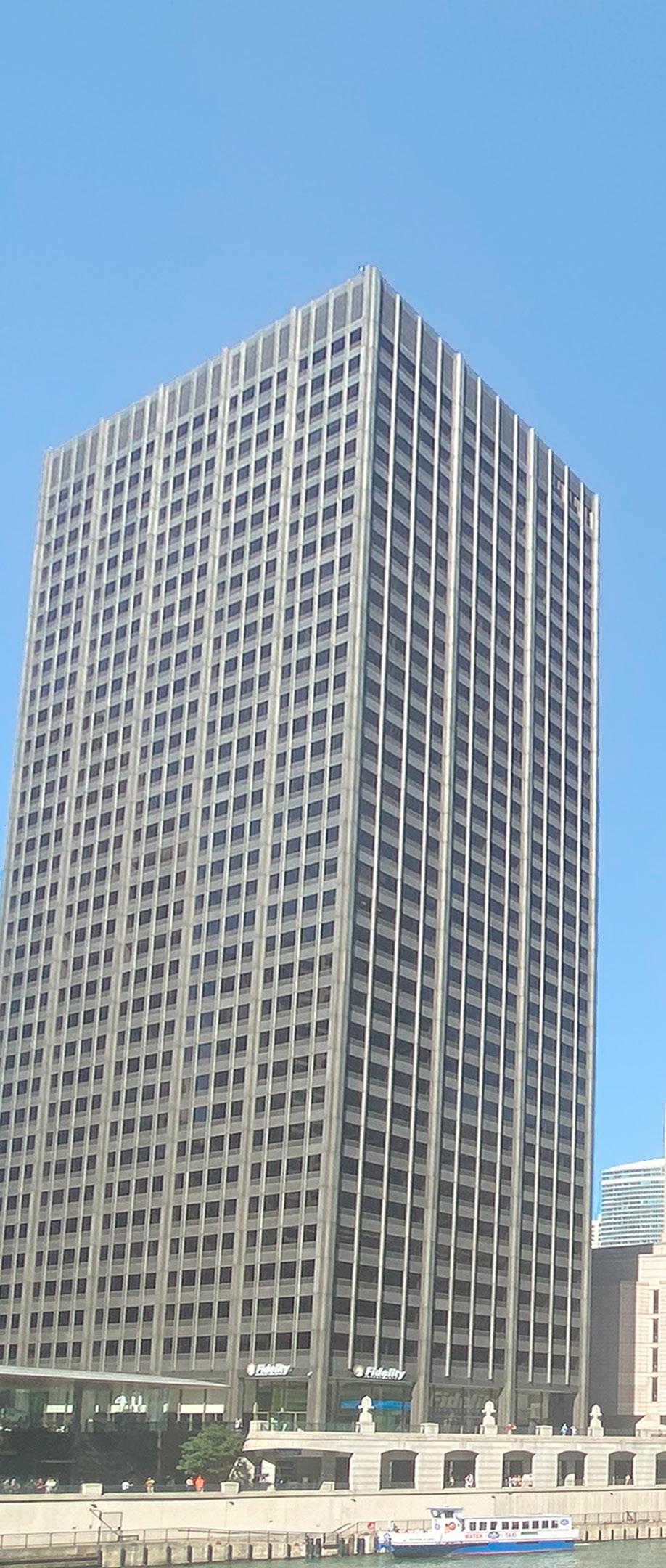
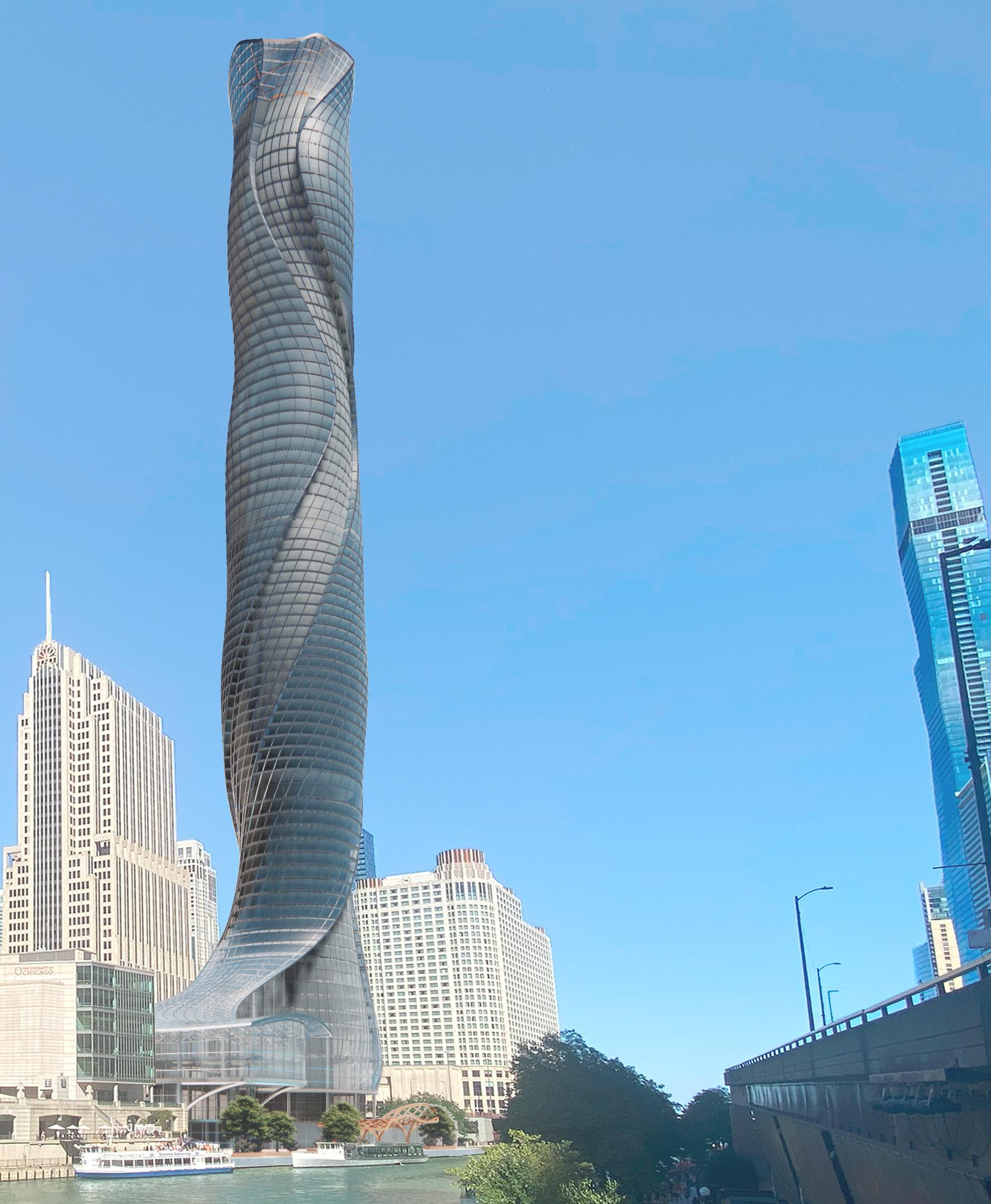
A mixed-use tower that incorporated a public podium, hotel, and condos by responding to the various “Flows” present in the immediate context.
The task was proposing the next skyscraper in Chicago’s storied high-rise history. Located on one of the last open lots near the mouth of the Chicago River, this location had the opportunity to be a gateway between Downtown Chicago and the lakefront. The design process focused on how to blend the verticality of a tower and the horizontality of the Chicago River. The design proposal was rooted in the concept of “Flow” from the horizontal to the vertical. This influenced the massing by metaphorically pulling the flow of the Chicago River across the site and up the tower. This created a dynamic design that provided for a gateway and produced a high-rise unlike any other in Chicago’s Skyline.
38 2ND YEAR GRAD
39 FLOW
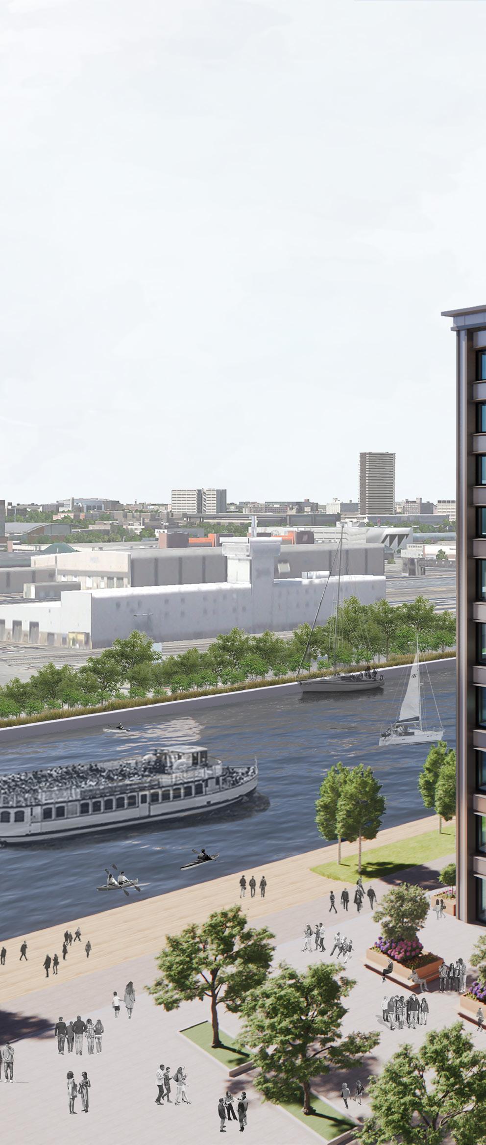
RIVERWALK
VIEW FROM SOUTH

02 CONVERGE 03 GATEWAY

40 2ND YEAR GRAD
DIAGRAMS
CONCEPT
01 FLOW
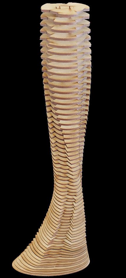
2. FLOW
TOWER ITERATIONS
1. TREE TRUNK
4. INITIAL PODIUM DESIGN
3. TWO TOWERS
ELEVATOR DIAGRAM
HOTEL(NORTH BANK)
CONDO(SOUTH BANK)
*2 SERVICE ELEVATORS FOR EACH USE TOWER HEIGHT = 1050 FEET
5 FLOORS, 15’ FL to FL.
CONDOS
23 FLOORS, 12’ FL. to FL. PENTHOUSES
INTERMEDIATE SKYGARDEN
HOTEL
21 FLOORS, 10’ FL. to FL.
INTERMEDIATE SKYGARDEN
12 FLOORS, 12’ FL. to FL. LOFTED
CONDOS SKYGARDEN MECHANICAL MECHANICAL MECHANICAL
PODIUM
7 FLOORS, VARIES FL to FL
6 FLOORS, 12’FL to FL PARKING GARAGE
41 FLOW
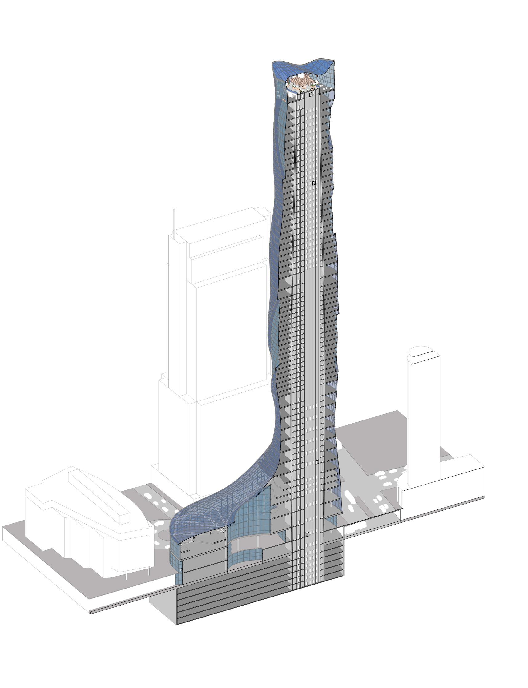
SECTION & ELEVATOR DIAGRAM
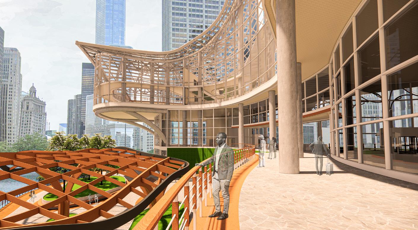
PERSPECTIVE
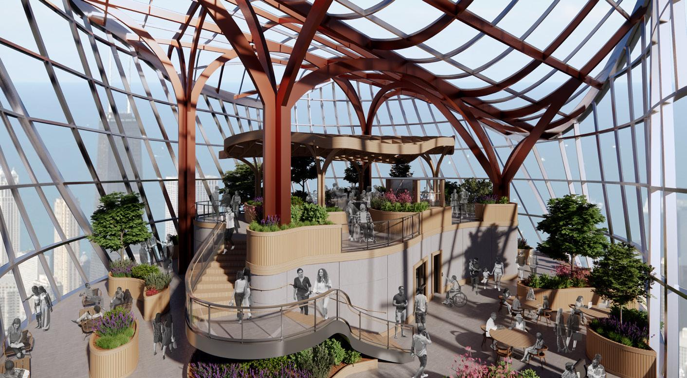
SKY-GARDEN
The tower is crowned with a sky-garden that captures the essence of the concept of Flow within a space. In the same way the tower was rising from the “flow” of the river, the “tree” columns rose out of the core and, like branches, the beams flowed out from the columns to form a dynamic roof canopy.
PEDESTRIAN ACCESS (SOUTH) FROM COLUMBUS DRIVE
On the south side, the podium curves away to reveal a path to Columbus Drive. In tandem with the gateway at the podium’s center, these gestures proactively engaged the ground plane to encourage human-scale movement between the plaza and Riverwalk level.
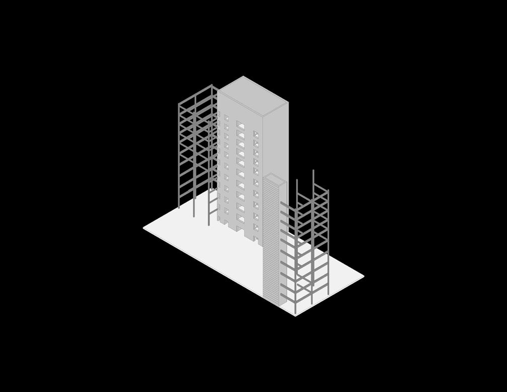
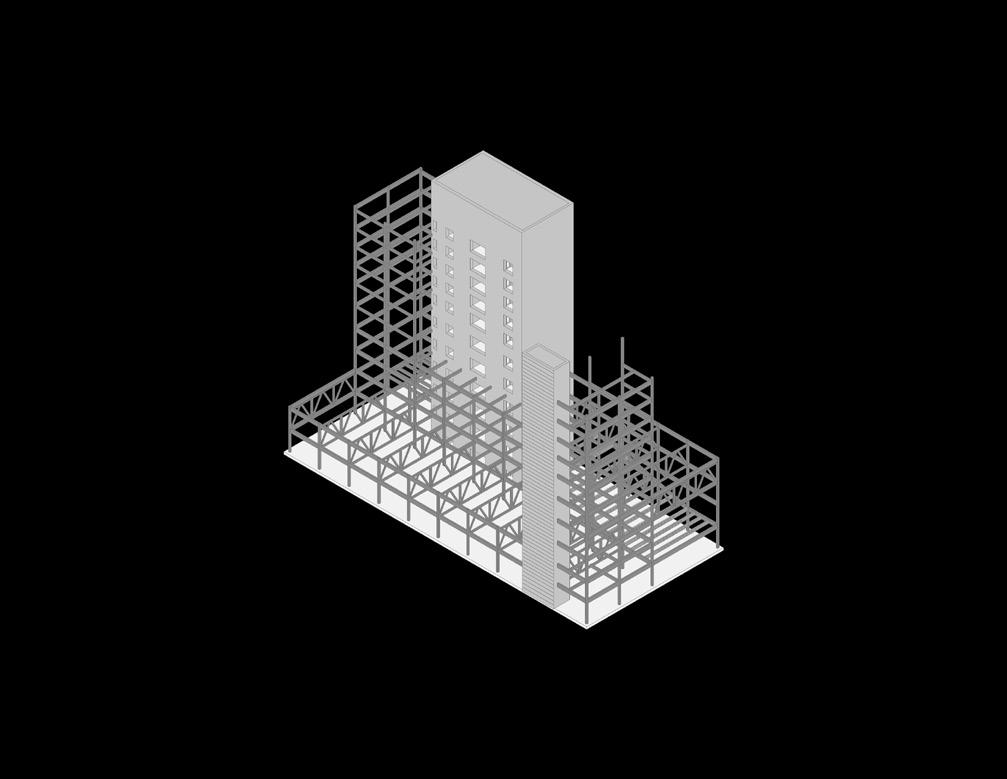
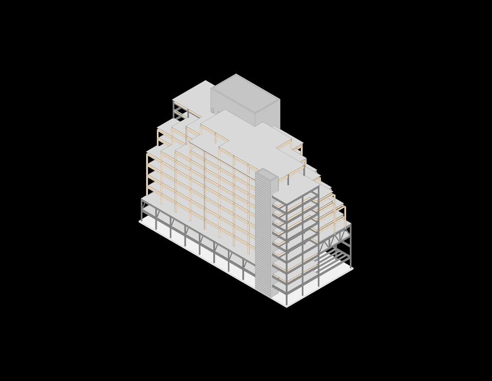
42 2ND YEAR GRAD
Reinforced Concrete Slab
Tapered Reinforced Concrete Super Core
Base: 70 ft. x 70 ft.
Top: 63 ft. x 56 ft.
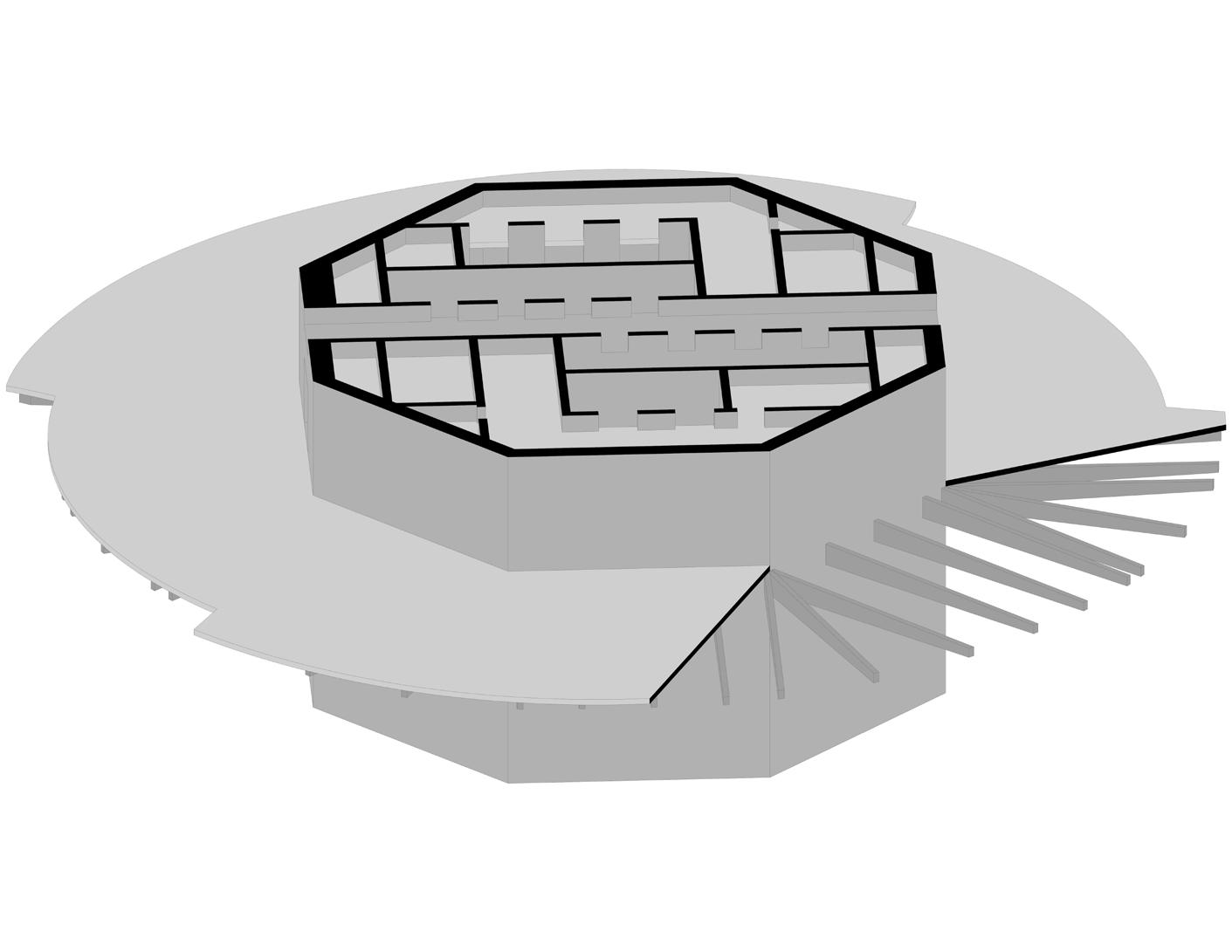
10 in. thick slab
Tapered Reinforced Concrete Beams
Depth: 30 in. to 16 in
The concept of Flow necessitated a seamless integration of the architecture and structure to achieve the massing. It required a response to the two rotating carvings, which articulated the concept and mitigated wind forces. Moreover, floor plate spans would need to vary to meet the required lease spans: 35 feet for hotel levels and 25–30 feet for condos. The solution was a Tapered Reinforced Concrete Super Core with its integrated gravity and lateral system. This system enabled the floor plates to effectively respond to the rotating carvings and varying lease spans, while avoiding inopportune column placement.
43 FLOW
SUPER CORE STRUCTURAL SYSTEM
LOFTED CONDO UNITS (UPPER)

44 2ND YEAR GRAD
LOFTED CONDO UNITS (LOWER)
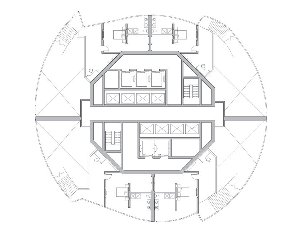
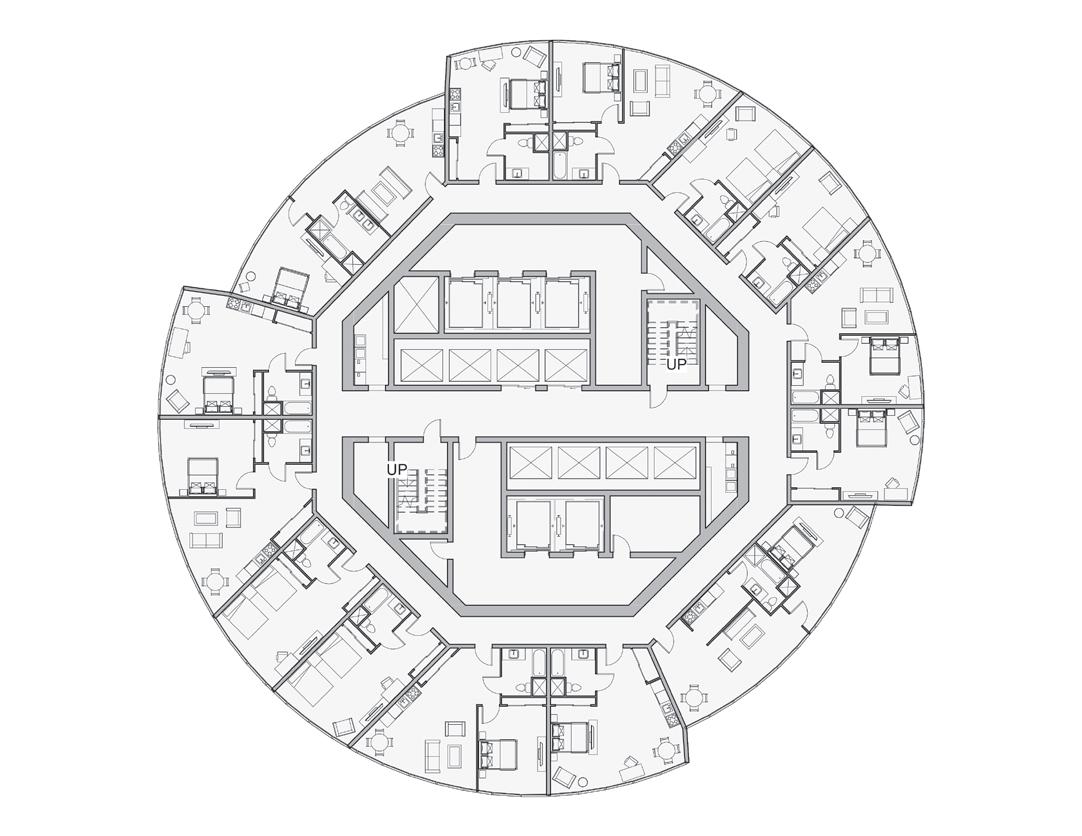
TYPICAL LOWER HOTEL FLOOR PLAN
0 100 FT 20 60
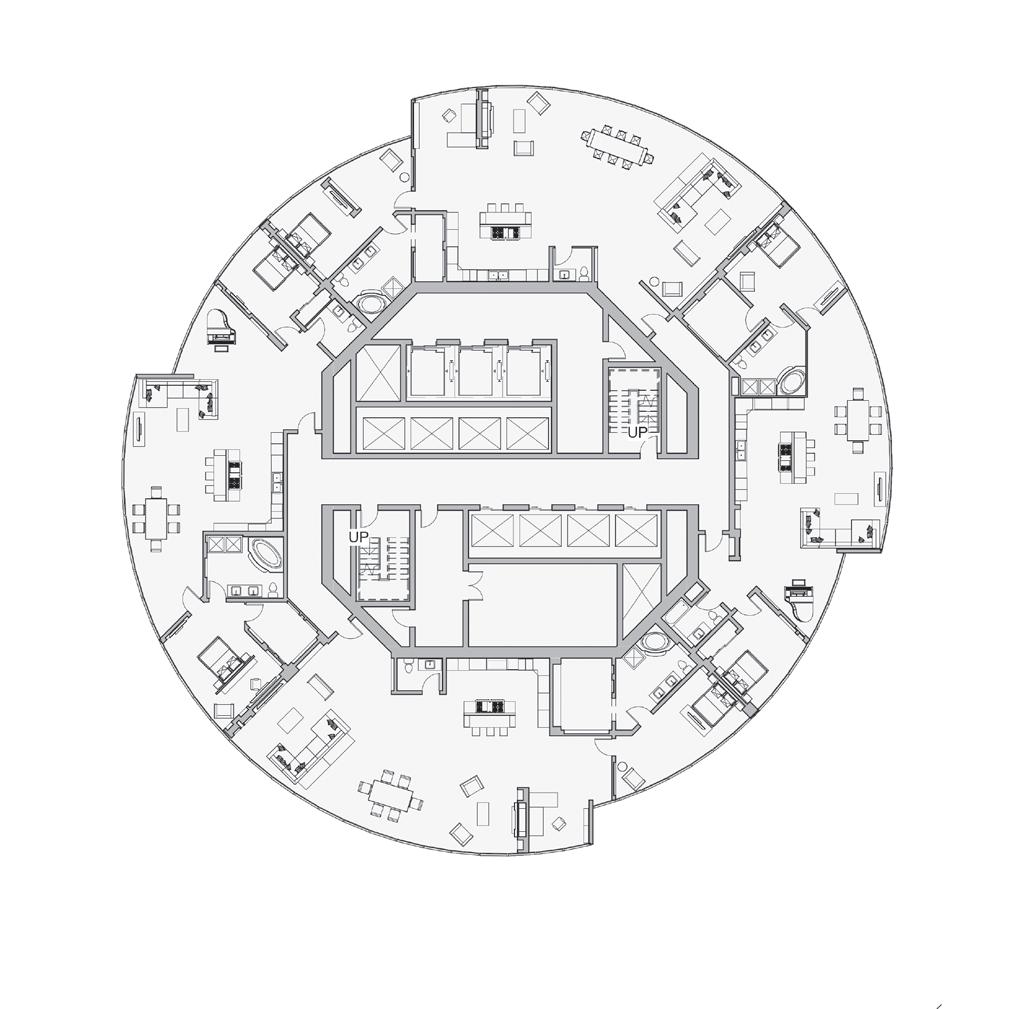
TYPICAL LOWER CONDO FLOOR PLAN
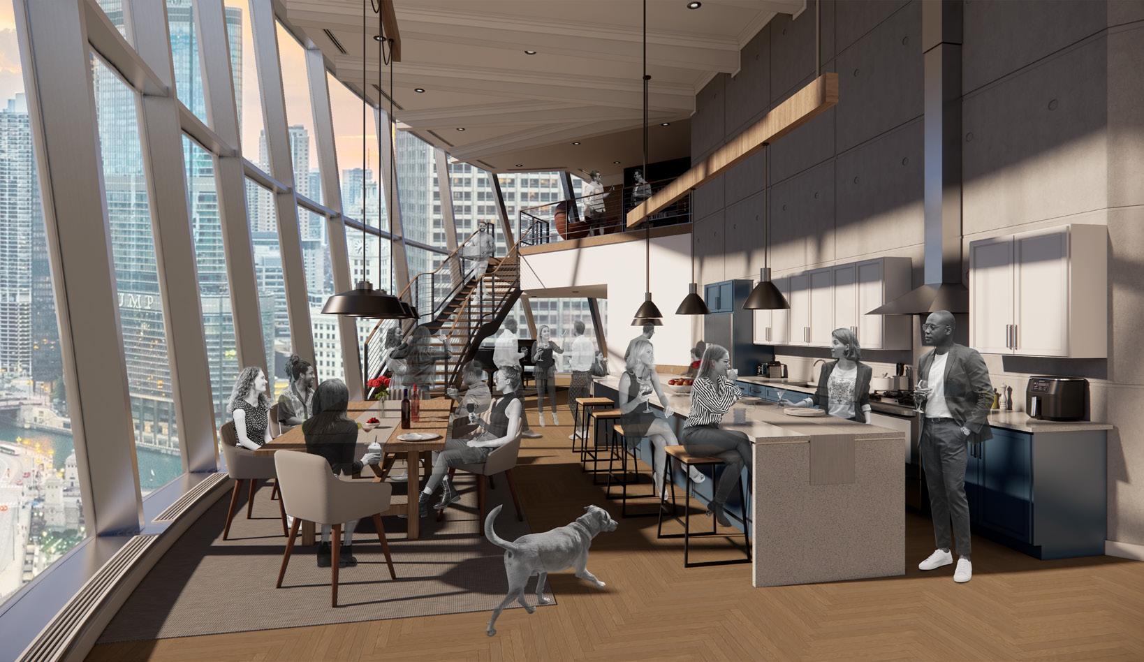
LOFTED CONDO UNIT
As condo units are placed higher in a tower, the visual connection to activity of the urban ground plane gradually fades. In response, lofted condo units were strategically introduced between the podium and hotel. This elevation placement preserved a closer connection to the vibrant life of the Riverwalk through providing residents with a unique and captivating perspective of the city’s energy. The double-height living area accentuated these views while prominently exhibiting the exposed octagon core and the articulation of the cantilever floor system.
45 FLOW
46 CONTACT INFORMATION PRESENTING DURING FINAL REVIEWS - FALL 2021 CONTACT INFORMATION: EMAIL: patrick.d.dillon3@gmail.com LINKEDIN: https://www.linkedin.com/in/patrick-dillon-65a763206/