Service Manual G424FE LP/Dual Fuel Engine G424F LP Engine G20P-5, G25P-5, G30P-5, G33P-5, G35C-5 GC20P-5, GC25P-5, GC30P-5, GC33P-5
Doosan Forklift Service Manual G424fe Lpdual Fuel Engine G424f Lp Engine Full download:
This is the cut pages sample. Download all 306 page(s) at: ManualPlace.com
SB4251E00 May. 2007
http://manualplace.com/download/doosan-forklift-service-manual-g424fe-lpdual-fuel-engine-g424f-lp-engine/
Important Safety Information
Most accidents involving product operation, maintenance and repair are caused by failure to observe basic safety rules or precautions. An accident can often be avoided by recognizing potentially hazardous situations before an accident occurs. A person must be alert to potential hazards. This person should also have the necessary training, skills and tools to perform these functions properly.
Read and understand all safety precautions and warnings before operating or performing lubrication, maintenance and repair on this product.
Basic safety precautions are listed in the “Safety” section of the Service or Technical Manual. Additional safety precautions are listed in the “Safety” section of the owner/operation/maintenance publication. Specific safety warnings for all these publications are provided in the description of operations where hazards exist. WARNING labels have also been put on the product to provide instructions and to identify specific hazards. If these hazard warnings are not heeded, bodily injury or death could occur to you or other persons. Warnings in this publication and on the product labels are identified by the following symbol.
WARNING
Improper operation, lubrication, maintenance or repair of this product can be dangerous and could result in injury or death. Do not operate or perform any lubrication, maintenance or repair on this product, until you have read and understood the operation, lubrication, maintenance and repair information.
Operations that may cause product damage are identified by NOTICE labels on the product and in this publication.

DOOSAN cannot anticipate every possible circumstance that might involve a potential hazard. The warnings in this publication and on the product are therefore not all inclusive. If a tool, procedure, work method or operating technique not specifically recommended by DOOSAN is used, you must satisfy yourself that it is safe for you and others. You should also ensure that the product will not be damaged or made unsafe by the operation, lubrication, maintenance or repair procedures you choose.
The information, specifications, and illustrations in this publication are on the basis of information available at the time it was written. The specifications, torques, pressures, measurements, adjustments, illustrations, and other items can change at any time. These changes can affect the service given to the product. Obtain the complete and most current information before starting any job. DOOSAN dealers have the most current information available.
1
Chapter 3. ENGINE MECHANICAL SYSTEM
G424F(FE) Service Manual Index 3 Index
GENERAL INFORMATION Precautions before Service .................................7 Tightening Torque.............................................10 Recommended Lubricants and Capacities.......11 Engine Model and Engine Serial Number.........12 General Specification........................................13 G424F/G424FE Engine Power and Torque........15
Chapter 1.
RECOMMENDED MAINTENANCE General Maintenance.........................................16 Test Fuel System for Leaks ...........................16 Inspect Engine for Fluid Leaks ......................16 Inspect Vacuum Lines and Fittings ................16 Inspect Electrical System..............................16 Inspect Foot Pedal Operation ........................16 Engine Oil Classification................................17 Checking Engine Oil Level............................18 Replacing Engine Oil and Filter .....................18 Checking Compressed Pressure...................19 Cooling System Maintenance............................20 Coolant Recommendation .............................20 Check Coolant Level.....................................20 Inspect Coolant Hoses..................................20 Checking coolant leaks.................................21 Specific gravity test.......................................21 Relation between Coolant concentration and Specific Gravity.............................................21 Checking and Adjusting Drive Belt ................22 Adjusting.......................................................22 Checking Belt for Damage............................22 Ignition System Maintenance............................23 Inspect Battery System.................................23 Inspect Ignition System.................................23 Inspection of Ignition Timing.........................23 Inspection of Spark Plug...............................24 Fuel System Maintenance.................................26 Replace LP Fuel Filter Element.....................26 Testing Fuel Lock-off Operation....................26 Pressure Regulator/Converter Inspection ......27 Inspect Air/Fuel Valve Mixer Assembly.........27 Inspect for Intake Leaks ................................27 Inspect Throttle Assembly.............................27 Checking the TMAP Sensor..........................27 Exhaust System Maintenance...........................27 Inspect Engine for Exhaust Leaks .................27 Maintenance Schedule......................................28
Chapter 2.
General Information...........................................30 Engine Outline..............................................30 Technical Specifications...............................31 Shells Selection Table..................................33 Recommended Torque Values......................36 Troubleshooting ............................................38 Engine Exploded View.......................................39 Intake manifold and gasket ...............................41 Exhaust Manifold and Gasket ...........................45 Timing Belt.........................................................47 Timing Belt Tensioner.......................................51 PCV Valve..........................................................52 Camshaft Timing Pulley and/or Seal.................55 Crankshaft Timing Pulley..................................55 Crankshaft Front Seal.......................................56 Camshaft Case Cover and Gasket ....................56
G424F(FE) Service Manual Index 4 Crankshaft Accessory Pulley ............................57 Timing Belt Rear Cover.....................................57 Rocker Arms, Linkage, Valve Lifters With Cylinder Head and Eegine...............................59 Cooling System..................................................60 Thermostat Housing..........................................66 Water Pump........................................................67 Lubrication System............................................68 Oil Pan................................................................71 Oil Pump.............................................................72 Oil Pump Assembly ...........................................73 Camshaft Case Assembly .................................74 Cylinder Head.....................................................78 Valve, Spring or Seal.........................................79 Engine Disassembly ..........................................81 Engine Assembly ...............................................85 Cylinder Block....................................................90 Crankshaft..........................................................91 Pistons and/or Connecting Rods......................97 Rings.............................................................. 9999 Chapter 4. ENGINE ELECTRICAL SYSTEM Specifications..................................................101 Ignition System................................................102 Wasted Spark DIS Ignition System..............102 Inspection of Ignition Coil............................103 Spark Plug Wire Inspection.........................104 Spark Plug Wire Replacement....................104 Spark Plug Replacement.............................105 Spark Plug Inspection.................................105 Charging System.............................................107 General Description ....................................107 Troubleshooting Procedure .........................110 STARTING SYSTEM.........................................115 General Description ....................................115 Diagnosis Procedure ...................................116 Start Relay Tests.........................................118 Troubleshooting ...........................................119
5. ENGINE MANAGEMENT SYSTEM (EMS) General Information..........................................121 Specifications..............................................121 Service Standard .........................................126 Component Location....................................127 G424FE EMS (Engine Management System) Overview...........................................................131 General Description .....................................131 LPG Fuel System Operation........................134 MPI Gasoline System Operation..................141 Electronic Throttle System...........................142 Ignition System............................................143 Exhaust System...........................................144 SECM..........................................................146 SECM Wiring Diagrams for G424FE ............149 G424F EMS (Engine Management System) Overview...........................................................152 General Description .....................................152 LPG Fuel System Operation........................155 Electronic Throttle System...........................159 Ignition System............................................159 SECM..........................................................159 SECM Wiring Diagrams for G424F LP Engine ....................................................................160
Chapter
EMS Inspection and Repair.............................161
Engine Control Module (SECM) ..................161
Camshaft Position Sensor...........................163
IAT (Intake Air Temperature) Sensor...........167
Oxygen Sensor (Pre-Catalyst).....................168
Oxygen Sensor (Post-Catalyst) ...................169
ECT (Engine Coolant Temperature) Sensor170 LP Fuel Temperature Sensor......................172
Angle Sensor-Accelerator...........................173
Transmission Oil Temperature Switch.........174
Ground Speed Limit Switch (optional) .........175 Electronic Throttle Body..............................176
Chapter 6. LPG FUEL DELIVERY
SYSTEM
G424FE LP System Inspection and Repair .....177 Removal and Installation .............................177 Hose Connections ................................178 Removal and Installation of N-2007 LP Regulator .............................................180 Removal and Installation of CA100 Mixer for G424FE ..........................................181 Tests and Adjustments................................183
N-2007 Regulator Service Testing........183
AVV (Air Valve Vacuum) Testing..........185 Connection of the MI-07 Service Tool...185 Idle Mixture Adjustment........................186 Parts Description.........................................189
CA100 Mixer for G424FE Engine .........189
N-2007 Regulator for G424FE Engine..191
G424F LPG System Inspection and Repair.....193
Removal and Installation .............................193
G424F Fuel System Connections .........194 Removal and Installation of N-2001 LP Regulator/Converter .............................195 Removal and Installation of CA100 Mixer for G424F
G424F(FE) Service Manual Index 5
............................................196 Tests and Adjustments................................198
........198 AVV
Idle
Adjustment........................201 Parts Description.........................................203
............203
Service ...............206
...............211 Chapter 7. MPI GASOLINE FUEL DELIVERY SYSTEM Specification.....................................................212 Components Location......................................213 Fuel Pressure Test ...........................................214 Injector..............................................................216 Fuel Pump.........................................................219 Chapter 8. BASIC TROUBLESHOOTING Preliminary Checks ..........................................220 Before Starting............................................220 Visual/Physical check..................................220 Basic Troubleshooting Guide..........................221 Customer Problem Analysis Sheet ...............221 Basic Inspection Procedure .........................222 Connector Inspection Procedure ..................223 Symptom Troubleshooting Guide Chart .......227 Basic Troubleshooting.....................................233 Intermittents.................................................233 Surges and/or Stumbles ..............................234 Engine Cranking but Will Not Start / Difficult to Start............................................................235 Lack of Power, Slow to Respond / Poor High Speed Performance / Hesitation During
N-2001 Regulator Service Testing
(Air Valve Vacuum) Testing..........200 Connection of the MI-07 Service Tool ...200
Mixture
CA100 Mixer for G424F Engine
CA100 Disassembly and Service ..........205 CA100 Disassembled
N-2001 Regulator for G424F Engine .....207 N2001 Regulator Disassembly Steps: ...209 N2001 Disassembled Service
G424F(FE) Service Manual Index 6 Acceleration................................................237 Detonation / Spark Knock............................239 Backfire......................................................240 Dieseling, Run-on.......................................240 Rough, Unstable, Incorrect Idle, or Stalling..241 Cuts Out, Misses.........................................243 Poor Fuel Economy / Excessive Fuel Consumption LPG Exhaust Smell ...............244 High Idle Speed ..........................................245 Excessive Exhaust Emissions or Odors.......246 Diagnostic Aids for Rich / Lean Operation...247 Chart T-1 Restricted Exhaust System Check248 Chapter 9. ADVANCED DIAGNOSTICS Reading Diagnostic Fault Codes.....................249 Displaying Fault Codes (DFC) from SECM Memory.............................................................249 Clearing Fault (DFC) Codes.............................249 Fault Action Descriptions ................................250 Fault List Definitions........................................250 Table 1. Fault List Definitions......................251 Table 2. Diagnostic Fault Codes (Flash Codes) ...................................................................261 Appendix Service Tool Software (MotoView)...................279 Introduction .................................................279 Connection of the Service Tool ....................280 MotoView Display Screens ..........................281 SECM field update with Service Tool ...........293 Ground Speed Limits (Option).........................297 LPG And LPG Fuel Tanks................................299 Regulatory Compliance....................................303 Special Conditions for Safe Use......................303 Abbreviations...................................................304
Chapter 1. GENERAL INFORMATION
Precautions before Service
Removal and Disassembly
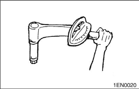
Tightening Torque
Tighten the part properly to specified torque.
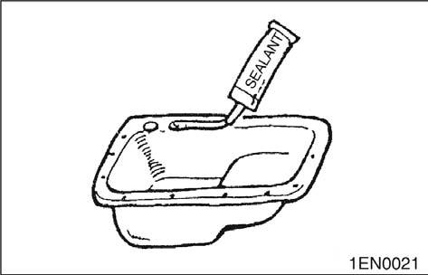
Sealant
For prevention of wrong installation or reassembly and for ease of operation, put mating marks to the parts where no function is adversely affected.
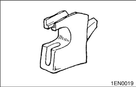
Special Tool
Use specified brand of sealant.
Use of sealant other than specified sealant may cause water or oil leaks.
Be sure to use Special Tools when their use is specified for the operation.
Use of substitute tools will result in malfunction of the part or damage it.

G424F(FE) Service Manual Chapter 1. General Information 7
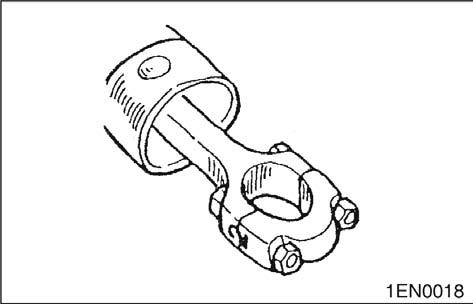
Replacement Part
Genuine Part
When oil seal, O-ring, packing and gasket have been removed, be sure to replace them with new parts.
However, rocker cover gasket may be reused if it is not damaged.
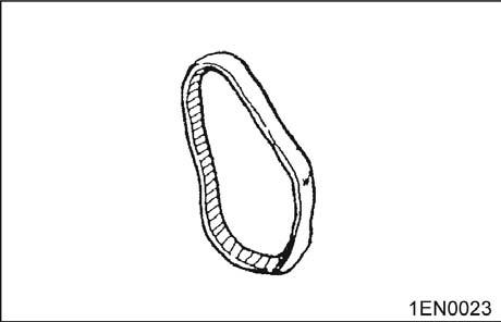
Rubber Parts
Do not stain timing belt and V-belt with oil or water. Therefore, do not clean the pulley and sprocket with detergent.
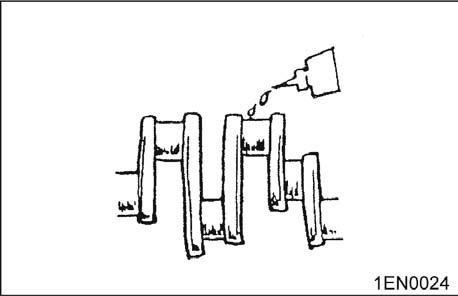
Oil and Grease
Before reassembly, apply specified oil to the rotating and sliding parts.
When the part is to be replaced, be sure to use genuine part.
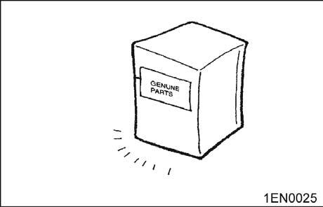
For selection of appropriate parts, refer to the Parts Catalog.
Electrical System
1. Be sure to disconnect the battery cable from the negative (-) terminal of the battery.
2. Never pull on the wires when disconnecting connectors.
3. Locking connectors will click when the connector is secure.
4. Handle sensors and relays carefully. Be careful not to drop them or hit them against other parts.

G424F(FE) Service Manual Chapter 1. General Information 8
Precautions for catalytic Converter
CAUTION
If a large amount of unburned gasoline flows into the converter, it may overheat and create a fire hazard. To prevent this, observe the following precautions and explain them to your customer.
1. Use only unleaded gasoline.
2. Do net run the engine while the truck is at rest for a long time. Avoid running the engine at fast idle for more than 5 minutes and at idle speed for more than 10 minutes.
3. Avoid spark-jump tests. Do spark-jumps only when absolutely necessary. Perform this test as rapidly as possible and, while testing, never race the engine.
4. Do not measure engine compression for an extended time. Engine compression tests must be made as rapidly as possible

5. Do not run the engine when the fuel tank is nearly empty. This may cause the engine to misfire and create and extra load on the converter.
6. Avoid coasting with the ignition turned off and during prolonged braking
7. Do not dispose of a used catalytic converter together with parts contaminated with gasoline or oil.
G424F(FE) Service Manual Chapter 1. General Information 9
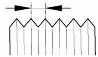
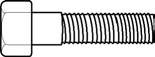
Tightening Torque
Tightening Torque Table of Standard Parts
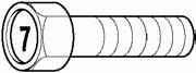
Bolt nominal diameter (mm) Pitch (mm) Head mark 4 Head mark 7
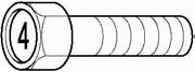
Torque (kg·m)
M5 0.8 0.3 ~ 0.4 0.5 ~ 0.6 M6 1.0 0.5 ~ 0.6 0.9 ~ 1.1 M8 1.25 1.2 ~ 1.5 2.0 ~ 2.5 M10 1.25 2.5 ~ 3.0 4.0 ~ 5.0 M12 1.25 3.5 ~ 4.5 6 ~ 8
M14 1.2 7.5 ~ 8.5 12 ~ 14 M16 1.5 11 ~ 13 18 ~ 21 M18 1.5 16 ~ 18 26 ~ 30 M20 1.5 22 ~ 25 36 ~ 42 M22 1.5 29 ~ 33 48 ~ 55 M24 1.5 37 ~ 42 61 ~ 70
M5 0.8 0.3 ~ 0.4 0.5 ~ 0.6 M6 1.0 0.5 ~ 0.6 0.9 ~ 1.1 M8 1.25 1.2 ~ 1.5 2.0 ~ 2.5
M10 1.25 2.5 ~ 3.0 4.0 ~ 5.0
NOTE: The torques shown in the table are standard vales under the following conditions.
1. Nuts and bolt are made of steel bar and galvanized.
2. Galvanized plain steel washers are inserted.
3. All nuts, bolts, plain washers are dry.
NOTE: The torques shown in the table are not applicable,
1. When spring washers, toothed washers and the like are inserted.
2. If plastic parts are fastened.
3. If oil is applied to threads and surfaces.
NOTE: If you reduce the torques in the table to the percentage indicated below under the following conditions, it will be the standard value.
1. If spring washers are used : 85%
2. If threads and bearing surfaces are stained with oil: 85%
G424F(FE) Service Manual Chapter 1. General Information 10
Recommended Lubricants and Capacities
Recommended Lubricants
Lubricant Specification Remarks
Engine Oil API Classification SJ or above SAE 10W30 or SAE 5W30
Coolant (Antifreeze) Automotive antifreeze suitable for gasoline engines having aluminum alloy parts Concentration level 50%(normal) Concentration level 40%(tropical)
Lubricant Capacities
Description G(C)20/25/30/33P-5
Oil Pan 4.25
Oil Filter 0.3
Engine Oil (liters) Total 4.5 Engine 3.0 Radiator & Hoses 6.0 Coolant (liters) Total 9.0
G424F(FE) Service Manual Chapter 1. General Information 11
Engine Model and Engine Serial Number
Engine Model Fuel Type
Emission Regulation
G424FE LP/Dual Fuel EPA/CARB* 2007 Compliant
G424F LP
* EPA: Environmental Protection Agency
* CARB: California Air Resources Board
G424FE Engine
• Comply with EPA 2007 Emission Regulation
• Electronic Control by ECM
• Certified LP/Dual Fuel System available
– Closed loop LP Carburetion system – Closed loop MPI Gasoline system
• 3-way Catalytic Muffler is standard
G424F Engine
• Not comply with EPA 2007 Emission Regulation
• Electronic Control by ECM
• Standard LP System available
– Open loop LP Carburetion system
• Muffler is standard
Indication of Engine Model and Serial Number
Engine Model Engine Serial Number
G424FE/G424F 30700001 to 39999999
Features and Benefits of G424FE/G424F Engine
• Al head with valve seat inserts
– Aluminum head and valve seat system
• SOHC 8 valve system
• Timing belt system
• Distributorless Ignition system
• Electronic control system by ECM (Engine control module)
– Drive-by-wire system –
Higher efficiency and lower fuel consumption – Min./Max. governor control –
Automatic engine protection from overheating and/or low engine oil pressure
– Automatic transmission protection from overheating
– Engine diagnostics by service-tool software
– Forklift ground speed limit (optional)
G424F(FE) Service Manual Chapter 1. General Information 12
General Specification
GENERAL DESCRIPTION
G424FE Engine G424F Engine
ENGINE TYPE: Water-cooled, Inline 4-Cycle, 4-Cylinders
COMBUSTION SYSTEM: Squish Combution Chamber
INTAKE MANIFOLD Cast Aluminum (with injector ports)
EXHAUST MANIFOLD Cast Iron (dual channel)
VALVE CONFIGURATION: SOHC, 2 Valves per Cylinder
VALVE LIFTER/LASH ADJUSTER Stationary Hydraulic Lash Adjusters VALVE ROTATOR Exhaust Rotator
CAMSHAFT DRIVE Timing belt system (20 mm Toothed Belt)
DISPLACEMENT: 2,405 cc (147 cid)
BORE x STROKE 87 mm (3.44 in) x 100 mm (3.94 in)
BLOCK STRUCTURE Grey Cast Iron
HEAD STRUCTURE Aluminum with seat inserts
COMPRESSION RATIO: 9.6:1
COMPRESSION PRESSURE: 1,240 kPa (180psi) Minimum Intake Valve: 17°30' BTDC/ 76°30' ABDC
VALVE TIMING: Exhaust Valve: 58°30' BBDC/ 35°30' ATDC
FIRING ORDER: 1-3-4-2 WEIGHT: 120 kg
ENGINE ROTATION: Counter-Clockwise (CCW) when viewed from Flywheel End FUEL TYPE: LPG, Dual Fuel (LPG or Gasoline)
CRANK VENTILATION Foul Air System with PCV IGNTION SYSTEM
IGNITION TYPE: Distributorless (waste spark)
IGNITIOIN TIMING: Electronic controlled by ECM
IGNITION COIL: 12 V operation volt
SPARK PLUGS: 0.035" (0.8-0.9 mm) Air Gap LUBRICATION SYSTEM
OIL PRESSURE: 282 - 324 kPa @ 1400 rpm
OIL TEMPERATURE:
Upper Limit: 125 °C (257°F) Recommended: 99 – 110 °C (210 - 230°F) Lower Limit:80 °C (176 °F)
OIL PAN Cast Aluminum
OIL PAN CAPACITY 4.25 L (EXCLUDES OIL FILTER)
OIL FILTER: 0.3 L
ENGINE OIL SPECIFICATION: API - SJ, SAE 10W30 or SAE 5W30
G424F(FE) Service Manual Chapter 1. General Information 13
G424FE Engine G424F Engine
COOLING SYSTEM
WATER PUMP ROTATION: Toothed Timing Belt Drive- Clockwise from front of engine
THERMOSTAT: Opening Temperature: 82°C (180°F) Fully Open Temperature: 95°C (203°F)
COOLING WATER CAPACITY: 3.0 L
LP FUEL SYSTEM
LP FUEL SYSTEM
MIXER:
Closed loop LP Carburetion System Open loop LP Carburetion System
Diaphragm Type Air Valve Assembly inside, Downdraft (Model: CA-100)
Diaphragm Type Air Valve Assembly inside, Downdraft (Model: CA-100)
REGULATOR: Two-Stage Negative Pressure Regulator (Model: N-2007) Two-Stage Negative Pressure Regulator (Model: N-2001)
FUEL TRIM VALVE (FTV): Dual Dither System None
FUEL FILTRATION: 40 Microns Maximum 40 Microns Maximum
GASOLINE FUEL SYSTEM
GASOLINE FUEL SYSTEM Closed loop MPI System and In-Tank Fuel Pump System
Electric Fuel Pump (12V)
FUEL PUMP MODULE
Fuel Filter & Strainer
Gasoline Pressure Regulator (3.5 bar)
FUEL INJECTOR ASS’Y Electric Fuel Injector (12V)
ENGINE ELECTRIC ENGINE CONTROL MODULE(ECM): 12 V operation volt, 48 pins of I/O
CRANK SENSOR VR (Variable Reluctance)
CAM SENSOR Hall sensor (Dual fuel engine only)
TMAP: Intake Air Temp. & Manifold Absolute Press. Sensor
PEDAL ANGLE SENSOR: Two-Output Signals (Installed on Accelerator Pedal)
OXYGEN SENSOR: Dual Oxygen Sensor System None
ECT-ECM: Engine Coolant Temperature Sensor for ECM
ECT-GAUGE Engine Coolant Temp. Sensor for GAUGE on Instrument Panel
TPS: Throttle Position Sensor (built in Throttle Body)
THROTTLE BODY: Electronic Throttle Body
LP FUEL LOCK-OFF: 12 V operation volt
ENGINE OIL PR. S/W: 14-41 kPa
STARTING MOTOR: 12 Volts, 1.4 kW
ALTERNATOR: 13.5 Volts, 80 A
EXHAUST SYSTEM
Muffler Catalytic Muffler Muffler (without catalyst)
G424F(FE) Service Manual Chapter 1. General Information 14
G424F/G424FE Engine Power and Torque
G424FE
G424F ENGINE MODEL unit G424FE-LP G424FE-DF(LP) G424FE-DF(GAS) G424F-LP
kW 46.2 44.7 46.2 hp 62 60 62 PS 62.9 60.8 62.9
RATED POWER rpm 2,550 2,550 2,550 N-m 181 172 181 ibf-ft 134 127 134 Kgf-m 18.5 17.5 18.5
MAX TORQUE rpm 2,200 2,200 2,200
GOVERNED SPEED rpm 2,600 2,600 2,600 LOW IDLE rpm 750 750 750
G424F(FE) Service Manual Chapter 1. General Information 15
Chapter 2. RECOMMENDED MAINTENANCE
Suggested maintenance requirements for an engine equipped with an MI-07 fuel system are contained in this section. The operator should, however, develop a customized maintenance schedule using the requirements listed in this section and any other requirements listed by the engine manufacturer.
General Maintenance Test Fuel System for Leaks
• Obtain a leak check squirt bottle or pump spray bottle.
• Fill the bottle with an approved leak check solution.
• Spray a generous amount of the solution on the fuel system fuel lines and connections, starting at the storage container.
• Wait approximately 15-60 seconds, then perform a visual inspection of the fuel system. Leaks will cause the solution to bubble.
• Listen for leaks
• Smell for LPG odor which may indicate a leak
• Repair any leaks before continuing.
• Crank the engine through several revolutions. This will energize the fuel lock-off and allow fuel to flow to the pressure regulator/converter. Apply additional leak check solution to the regulator/ converter fuel connections and housing. Repeat leak inspection as listed above.
• Repair any fuel leaks before continuing.
Inspect Engine for Fluid Leaks
• Start the engine and allow it to reach operating temperatures.
• Turn the engine off.
• Inspect the entire engine for oil and/or coolant leaks.
• Repair as necessary before continuing.
Inspect Vacuum Lines and Fittings
• Visually inspect vacuum lines and fittings for physical damage such as brittleness, cracks and kinks. Repair/replace as required.
• Solvent or oil damage may cause vacuum lines to become soft, resulting in a collapsed line while the engine is running.
• If abnormally soft lines are detected, replace as necessary.
Inspect Electrical System
• Check for loose, dirty or damaged connectors and wires on the harness including: fuel lock-off, TMAP sensor, O2 sensors, electronic throttle, control relays, fuel trim valves, crank position sensor, and cam position sensor.
• Repair and/or replace as necessary.
Inspect Foot Pedal Operation
• Verify foot pedal travel is smooth without sticking.
G424F(FE) Service Manual Chapter 2. Recommended Maintenance 16
Engine Oil Classification
Recommended API classification: Above SJ
Recommended SAE viscosity classification
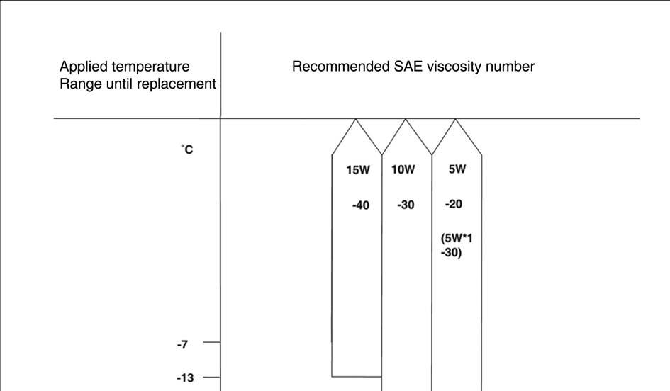
*1. 10W-30 engine oil is recommended If 10W-30 is not applicable, proper engine oil will be possible according to temperature ranges.
The following lubricants should be selected for all engines to enhance excellent performance and maximum effect.
1. Observe the API classification guide.
2. Proper SAE classification number should be selected within ambient temperature ranges. Do not use the lubricant with SAE classification number and API grade not identified on the container.
G424F(FE) Service Manual Chapter 2. Recommended Maintenance 17
Checking Engine Oil Level
Replacing Engine Oil and Filter
CAUTION
Prolonged and repeated contact with mineral oil will result in the removal of natural fats from the skin, leading to dryness, irritation and dermatitis.
In addition, used engine oil contains potentially harmful contaminants which may cause skin cancer.
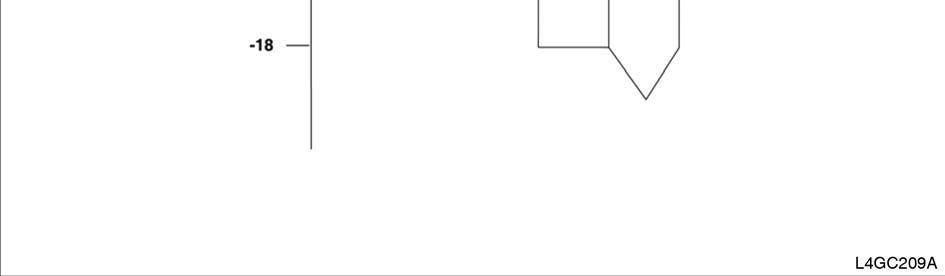
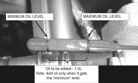
1. Check that the oil level is between “MIN” and “Max” marks on the engine oil level gauge.
2. If the oil level is below “MIN” mark, add oil until the level is within the specified ranges.
3. Check the engine for oil contamination and viscosity and replace if necessary.
Exercise caution in order to minimize the length and frequency of contact of your skin to used oil. In order to preserve the environment, used oil and used oil filter must be disposed of only at designated disposal sites.
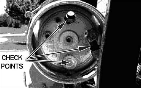
1. Drain engine oil.
1) Remove the oil filler cap.
2) Remove the oil drain plug, and drain the oil into a container.

2. Replace oil filter.
1) Remove the oil filter.
2) Check and clean the oil filter installation surface.
3) Check the part number of the new oil filter is as same as old one.
4) Apply clean engine oil to the gasket of a new oil filter.
5) Lightly screw the oil filter into place, and tighten it until the gasket contacts the seat.
6) Tighten it an additional 3/4 turn.
G424F(FE) Service Manual Chapter 2. Recommended Maintenance 18
Doosan Forklift Service Manual G424fe Lpdual Fuel Engine G424f Lp Engine Full download:
This is the cut pages sample. Download all 306 page(s) at: ManualPlace.com
http://manualplace.com/download/doosan-forklift-service-manual-g424fe-lpdual-fuel-engine-g424f-lp-engine/

