
selected academic and professional works 2019-2024

selected academic and professional works 2019-2024
Surrey Hills, VIC, 3127
+61 458 032 676 pat-dennis@hotmail.com linkedin.com/in/patrick-m-dennis/
BACHELOR OF ENVIRONMENTS
THE UNIVERSITY OF MELBOURNE Architecture Student ID: 699033
Graduated 2019
VICTORIAN CERTIFICATE OF EDUCATION
CAMBERWELL GRAMMAR SCHOOL
Graduated 2013
WORKS https://issuu.com/patdennis
ACADEMIC AND PROFESSIONAL

Drafting and documentation.
• Organised thinker.
• Technologically proficient.
• Interpersonal communication skills (clients, stakeholders, etc.). Understanding of construction terminology.
Graduate of architecture and design with a keen interest in healthcare design particularly. Eager to further my understanding of the discipline while undertaking the M-ARCH program.
A motivated worker with experience working in a variety of team structures involving multi- disciplinary collaboration. I aspire to deliver effective and pragmatic design directed at positive outcomes for targeted users. A background in healthcare gives me valuable insight into how these outcomes may be delivered, particularly to more vulnerable users.
Finding work at Plain Architecture has given me an invaluable insight into the more tangible elements of the field, clarifying how considered design can affect the human experience in profound ways. With an intense attention to detail and strong desire to learn, feel prepared to kick-start my career in architecture and design.
STUDENT ARCHITECT | APRIL 2022 - PRESENT
Plain Architecture is a small architecture firm that prioritises the relationship between architecture and the environment. Emphasis is placed on environmentally and economically sustainable design solutions that are tailored to the end user. Applications are largely in small to medium-scale residential architecture, with some healthcare-related projects in Victoria and Tasmania. This role has been vital in understanding the built environment outside of the modelling and drafting space.
• Employing ArchiCAD for drafting in two and three-dimensional space.
Creating and developing planning and construction documentation under the supervision of an accredited architect.
• Translating design intent into tangible drawings.
Creating detailed specifications for material choice, design directives and product schedules.
• Conducting site visits to establish compromises with tradespeople, consultants and clients.
• Working within building regulations to create realistic designs that are consistent with client desires.
• Observed and participated in client consultation to determine functional and spatial requirements for structures.
Back-of-house architectural work - defect reports, hazardous material reports, etc.
• ArchiCAD
• Rhinoceros3D
• Grasshopper3D AutoCAD
• SketchUp
• Adobe Photoshop
• Adobe Illustrator
• Adobe InDesign Rendering
• Freehand sketching
BUPA EMPLOYEE OF THE MONTH
• February 2017. October 2018.
• April 2020.
• March 2022.
HOBBIES
• AFL footballer for Old Camberwell Grammarians Football Club.
• Long-distance running.
• Architectural history.
• Drawing, sketching, photography and digital visualisation.
• Film and television.
PATIENT SERVICES ASSISTANT | 2014 - 2024
MELBOURNE PRIVATE HOSPITAL (HEALTHSCOPE)
Worked in a variety of clinical specialties including Intensive Care, Cardiology, Neurosurgery, Operating Theatres, Supply and Requisitions performing a wide range of roles. Studied various interconnected elements of the healthcare system through an architectural lens, critically analysing deficiencies and room for improvement. Conversations with various stakeholders giving insight into potential for better-tailored design outcomes.
• Assisted in acute patient care using appropriate equipment in accordance with moving and handling policies, providing effective bedside care.
• Integrated into a complex collaborative ecosystem to improve patient outcomes.
• Participated in minor maintenance of medical equipment to assist and improve department function.
• Conducted supply monitoring and ordering in Intensive Care and Cardiac Cath Lab settings.
Facilitated scans and other medical procedures for patients with a wide range of mobility requirements.
ARCHITECTURAL ASSISTANT | 2011
J W SADLER ARCHITECTS (WORK EXPERIENCE)
J W Sadler is a mid-sized architecture firm involved in health, educational, (multi) residential, hospitality and community buildings. An effective introduction into the design and delivery process.
• Worked under accredited architects in an assistant sense, particularly with drafting and documentation responsibilities.
• Completed site appraisals during construction, observing links between construction documentation and real-world application.
• Utilised AutoCAD to complete designs, model renderings and specification details.
WILLIAM GOODSIR KAREN JUKES
ARCHITECT PLAIN ARCHITECTURE
P: 0408 396 258
E: goodsir@plainarchitecture.com.au
MANAGER OF HOTEL SERVICES
HEALTHSCOPE
P: 0425 791 057
E: Karen.Jukes@healthscope.com.au
LEANNE UMSTAD MARIE PARDOE
GENERAL MANAGER
HEALTHSCOPE
P: 0408 341 177
E: Leanne.Umstad@healthscope.com.au
NURSE UNIT MANAGER
HEALTHSCOPE
P: 0479 106 450
E: mcshome@aol.com


WELLNESS THROUGH COMMUNITY
ARCHITECTURE DESIGN STUDIO: FIRE
MOYOLA LODGE
PROFESSIONAL WORK
MAFEKING HOUSE
PROFESSIONAL WORK
MILLSWYN HOUSE
PROFESSIONAL WORK
WINTRINGHAM BOARDROOM TABLE
PROFESSIONAL WORK
MODEL MAKING CONSTRUCTION DESIGN
ARCHITECTURE DESIGN STUDIO: FIRE
ABPL30037, 2019 ROBYN
Architecture Design Studio: Fire presents the opportunity to develop something of a hybrid typology with community and health at its core. It intends to satisfy a number of Maslow’s hierarchy of needs through the built form; allowing for members of the greater Carlton region to meet, belong, relax, educate and generally fortify themselves. The design intervention that I have adopted reconciles the dualities at play - integrating the disparities in age, income, ethnicity and ability of the catchment area. The result is a centralised idea of community health; acknowledging these differences to bring them together in a cohesive whole. This manifests itself in the architecture through two distinct approaches with two distinct feelings. These convene into a warm welcoming central space that enables community cross-over while in the pursuit of wellness.
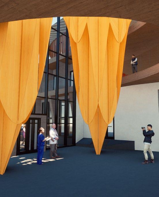
Internal perspective of Carlton Community Healthcare Centre, highlighting the formal void space. (bottom middle) Internal perspective of CCHC, highlighting the informal undercroft space. (top right)
render of CCHC, as seen from a southern viewpoint. (bottom right)
render of CCHC, as seen from a western viewpoint.


ACTIVATING THE COURTYARD
(top left)
Conceptual diagrams of plan development for CCHC. (middle left)
Basement Floor Plan of CCHC (1:500). (bottom left)
Ground Floor Plan of CCHC (1:500). (middle top)
First Floor Plan of CCHC (1:500). (middle top)
Secoond Floor Plan of CCHC (1:500). (right)
Site and Roof Plan of CCHC (1:500).


The Moyola Lodge project is a staged redevelopment of a 50-bed nursing home in Shepparton. This project presented a foray into healthcare design, which is inherently a complex typology. This was made only more complex by needing to retain living spaces for residents throughout the construction process. Essential considerations included hygiene standards, accessibility standards, safe material selections and strong attention to public (support staff) and private (residents). Personally, this project exhibited how directly our decisions as architects affect the end user. Moyola called for a new framework of thinking - one that required stepping out of myself and urging careful and empathetic design for a potentially vulnerable end user.
Given that the Moyola redevelopment was such a significant undertaking, my responsibilities were incredibly varied. I contributed and coordinated all documentation for planning and building permit purposes, yet most of the design thrust was left to partners at Plain Architecture. I contributed significantly toward meeting accessibility requirements, developing structural responses, material and product selections, dealing with consultants and developing schedules, among other things. A valuable introduction to a more complex style of architectural design.


645 MAFEKING ROAD, MAFEKING PROFESSIONAL WORK PLAIN ARCHITECTURE, 2024
Mafeking House is a proposed development in the Grampians intended to replace several disparate dwellings that were ravaged by bushfires in 2019. The brief offered by the client requested a cost-effective dwelling as a home base while he worked to rebuild the other dwellings on the large Mafeking site. The client works in elevator manufacture and requested that physical components of his business be integrated into the design as a cost-effective solution with a personal touch (the cladding is comprised of angled elevator doors). Bushfire considerations and setbacks were a significant consideration in this case, as were the inherent quirks of integrating non-standard building components.
(top left)
Ground Floor Plan of Mafeking House (1:100).
(top middle)
First Floor Plan of Mafeking House (1:100).
(top right)
Roof Plan of Mafeking House (1:100).


This was a significant opportunity to assist with establishing a design response from ground zero. I was given the opportunity to handle almost all dealings with the client and establishing a design response from the first client meeting. While this work was supervised and checked with a licensed architect, I led a lot of the work on this project. This proposal is still basic and a work in progress, but an excellent opportunity to showcase my ability to generate a design response sufficient for town planning applications.

Millswyn House is a substantial extension to a single-story terraced residence in South Yarra. The proposed extension maximises the narrow plot by increasing the footprint toward the back of the block. In order to maximise exposure to natural light, a first-floor balcony was added, in addition to multiple upgrades to amenities and conveniences. An additional bedroom, bathroom and laundry were added. The site posed some challenges, principal of which was the shared party wall and proximity to neighbours. Consequently, overlooking and sun study analyses were required for town planning purposes.


I joined this project shortly after sketch design. Therefore, much of my responsibility lay within refining design thrust and publishing documentation for town planning and building permits. Other minor responsibilities included joinery design, developing details and design of wall types and cladding systems. Consultation with clients led to iterative design with multiple resolved outcomes being developed and documented.
As a Student of Architecture, my roles were largely in the documentation and modelling space. I collaborated with a licensed architect to determine the design thrust within Wintringham’s set parameters. I was also tasked with coordinating consultation with sub-contractors in order to determine quotes and obtain industry advice. I was privileged enough to contribute to assembly and testing of components post laser cutting. An excellent opportunity to see how CAD becomes a concrete artefact. I learnt a significant amount about the properties of steel and timber through hands-on experimentation.
(top left)
Plan (1:100)
Table on-site in the Wintringham board room. Also expressed are the conduits for power supply and data connection.
(bottom left)
Axonometric (1:250)
The steel frame that makes up the table’s support structure. Provided the basis for client meetings and structural logic for sub-contractors.
(right)
A sample selection of isolated steel components that were sent to be laser cut. Considerable accuracy was required in an attempt to minimise errors and further laser cutting or grinding.
Wintringham is a not-for-profit organisation that establishes housing opportunities for elderly homeless individuals. Previous work with Wintringham lead to an opportunity to design a boardroom table for their corporate office. Many of the lessons learnt through architectural practice were able to be deployed through drawings for steel and timber manufacture. In many ways, this was a microcosmic exercise in design - exhibiting skills of precision and material consideration. The outcome is a 6.4m long Jarrah-clad table (capable of seating 20), supported by laser cut steel framing and Jarrahclad MDF for the legs. Electrical conduits are also integrated for data supply and GPOs.


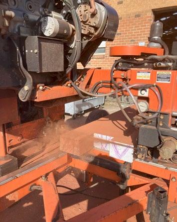


(above; left to right)
Solid 200 x 200 Jarrah posts are sawn into 6-7mm veneer boards using a hydraulic portable sawmill.
Veneer boards are laid out. These are used to 16mm MDF for the tabletop and legs that encapsulate the steel frame.
The veneer boards are run through a surface planer machine before they are cut based on a designed template.
STEEL MANUFACTURE AND ASSEMBLY
(left to right; top to bottom)
Laser cut steel components, fully assembled and bolted into place. Ready for timber to be integrated.
Centre beams are welded to end plates, which are then bolted to leg cleats.
An aluminium straight edge was used to fine-tune any bowing and ensure a level finish between the struts.
Bolting the centre beam outriggers to centre beams through welded legs.
Equal angle slotted tags are welded to struts and bolted to the outside rail with a pinned connection. This enables fine-tuning during assembly.


Full construction model at 1:20 of Western BACE, exhibiting peeled back components that reveal how construction was achieved.
(below, middle)
First floor slab is achieved through a hollowcore slab system.
(below, bottom)
Precast beam to hollowcore connection, exhibiting reinforcement connection (some prestressed). (right)
Strip footings with exposed reinforcement mesh, expressing slab to footing connection.


Construction Design offered an opportunity to break down a real design (being Six Degrees Architects’ Western BACE) through a 1:20 three-dimensional model of a detail section. This exercise showcased a model making skillset, while expressing understanding of the components that combine to create the built form. This model required the student to interpret construction photographs in addition to various design documents from architects, engineers and manufacturers. The result is an exhibition of construction logic and processes that synthesise into a complex commercial building. A valuable exercise which gave a glimpse into how drawings are translated into tangible construction.


Peeled back flat roof structure, complete with parapet. Insulation and crossbracing evident under profiled roof sheeting. (middle left)
cladding system extends above the roof line to form the parapet.
Supported by a series of steel battens; protected with vapour permeable wall wrap.
Underslab heating achieved through hydronic heating conduits. (middle)
Rear view of the model; expressing how interior space achieved through the precast concrete system. Some additional roof structure is revealed here. (above)
Sun shading system, composed of powder coated perforated steel panels, columns and beams.