


® Volume 23 Number 4 - April 2023
The leading innovator supplying cutting-edge integrity solutions. Together we can ensure sustainable decision-making. Our combination of advanced inspection systems and expert consultants delivers a comprehensive understanding of asset safety, lifetime, and performance.
Comprehensive Asset Integrity Management

www.rosen-group.com
C O NTENTS
03. Editor's comment
05. Pipeline news
Updates on Power of Siberia 2, EastMed and Transgaz Black Sea pipelines.
KEYNOTE ARTICLES: COMPLIANCE AND STANDARDS

8. On the path to zero


To achieve our safety goals, we need to thoroughly study lower consequence events to learn from past mistakes, says Sara Lyons, Pipeline Accident Investigator, National Transportation Safety Board (NTSB), USA.
lexible pipes have been revolutionary force in beginning in World War when they were used to supply fuel to troops in northern France. The pipe used readily available materials arranged in way that made flexible and easy to install subsea at record speeds, mitigating the risk of bombing raids and casualties. Today, flexible pipes are used in offshore Despite their versatility, flexible pipes make up only 15% of the worldwide pipeline market With diameters ranging from 22 in., the most pipes were initially designed for shallow waters, but have waters, with the deepest on record being 3000 m in the Gulf of Mexico. In the coming years, there significant demand for flexible risers and flowlines at 2900 m. Today, design pressure capacities reach as high as 750 bar (10 in.)
and 900 bar (8 in.) with design temperatures reaching as and they continue to be a critical tool for the oil and gas industry. Rigid or flexible pipes? There are several reasons why both flexible and rigid pipes can be technical enablers, and consequently the only pipes, however, could go either flexible or rigid, often triggering passionate debate: Is there significant cost most reliable? How does the type of field layout impact What is the most economic considering the complete Answering these questions is task for talented concept and front end engineering design teams. However, certain variables come into play as well: lack of experience with either option, out of date information, or an incorrect
Roberta Pires, Flexible Pipe Systems Early Engagement Director, Baker Hughes, discusses features to be considered in a comparison between rigid and flexible pipes. 25
injuries. To achieve zero, the focus must extend beyond these minimum safety standards. For example, in the NTSB’s investigation of an accident that reviewed two industry guidance documents intended to help pipeline operators maintain PHMSA-compliant operator as one that was subject to PHMSA’s OQ rules. Similarly, the affected pipeline operator did not include this task in Nevertheless, the NTSB determined that the operator’s procedures and training practices did not prepare workers to recognise and safely respond to abnormal operating conditions. the lives of two men, leaving five surviving witnesses, two of whom were also injured. regulations]”. Industry representatives said that launching and receiving pigs did not meet this criterion. In adopting workers to safely respond to foreseeable, abnormal operating Let’s examine the circumstances of the Farmersville completed the first in a series of pig loadings, when they suspected that the mainline valve was leaking because the flare did not extinguish as expected. They adjusted the valve subsequent runs. On the day of the accident, worker opened in. valve tip, where it successfully ignited. As natural gas pressure the launcher decreased and less natural gas flowed to the flare tip, the work crew observed the flame die down and extinguish. 9 8
PAGE 8 To achieve our safety goals, we need to thoroughly study lower consequence events to learn from past mistakes, says Sara Lyons, Pipeline Accident Investigator, National Transportation Safety Board (NTSB), USA.
15. Managing the Mega Rule
Dr James Dean, CEO, Plastometrex, UK, introduces a novel tool for pipeline integrity management programmes and Mega Rule compliance.
21. Meeting a range of requirements
By working with the end user, product designs can be offered to meet a wide variety of specifications, thereby streamlining project acceptance, says Morgan Sledd, Stark Solutions, USA.
PIPELINE INTEGRITY SYSTEMS
25. Flexible or rigid: the big debate


Roberta Pires, Flexible Pipe Systems Early Engagement Director, Baker Hughes.
INTEGRITY AND INSPECTION
31. Analysing ILI tools
Lance Wethey, Technical Solutions Specialist, ROSEN, USA.
DAMAGE AND DEFECT ASSESSMENT

39. NDT: the ticket to pipeline damage assessment
Danny Keck, President, American Society for Nondestructive Testing (ASNT) and Independent Inspection, USA.
43. Inspect the unexpected Sylvain Cornu, Electromagnetic Engineer, NDT Global.
47. Looking above for the answers below
Abhinandan Arya, Vice President, Head of Technology – Solutions, Synspective Inc., Japan.
PIPELINE SERVICES AND MAINTENANCE


53. Automating data collection
Tom Krikke, Commercial Director, HiberHilo, Netherlands.
OFFSHORE OPERATIONS

59. Dye as detection?
Kevin Parker, Managing Director, OceanTools Ltd, UK.
OFFSHORE ASSETS
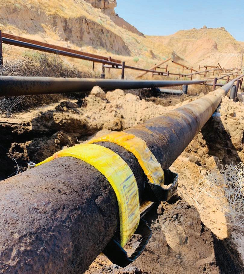
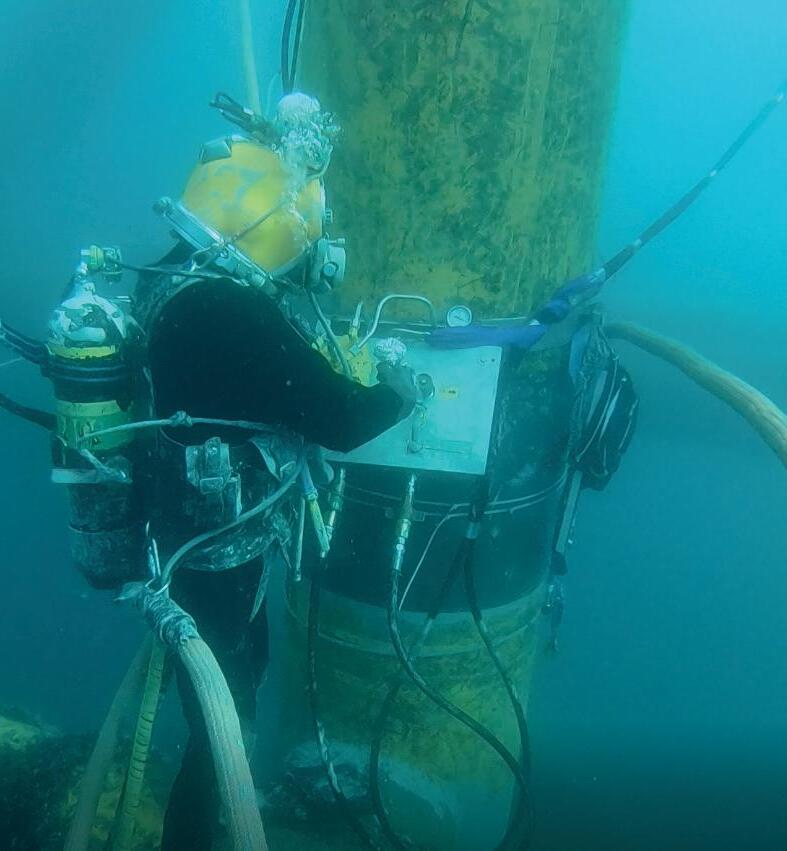
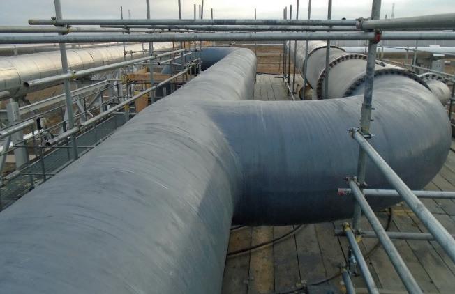
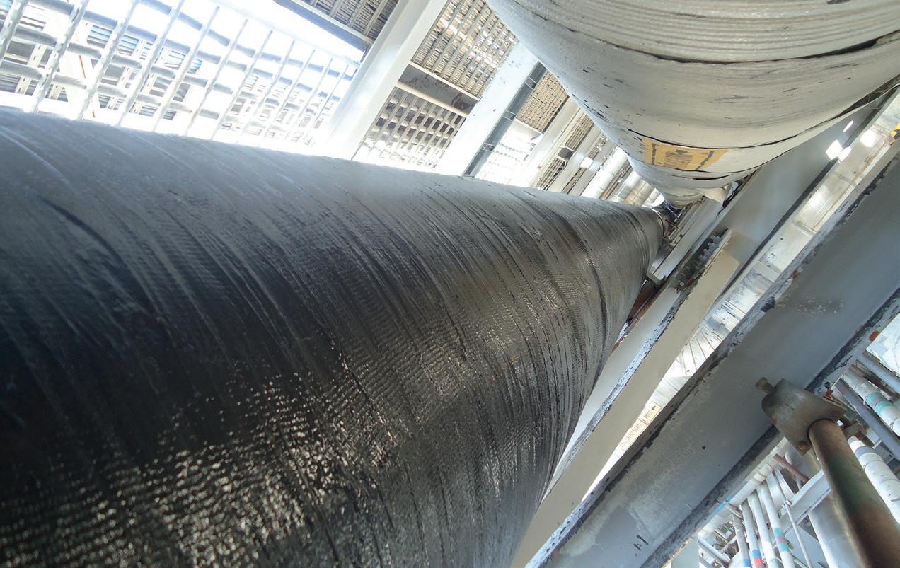
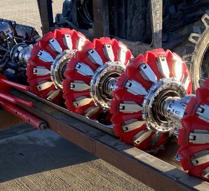
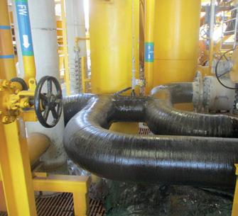
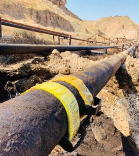
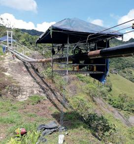
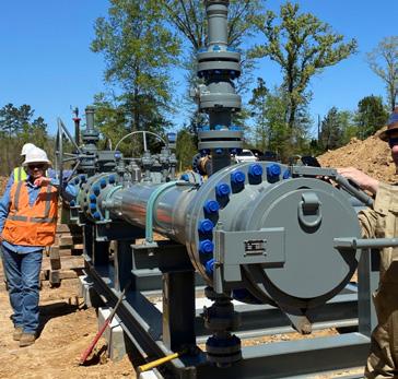
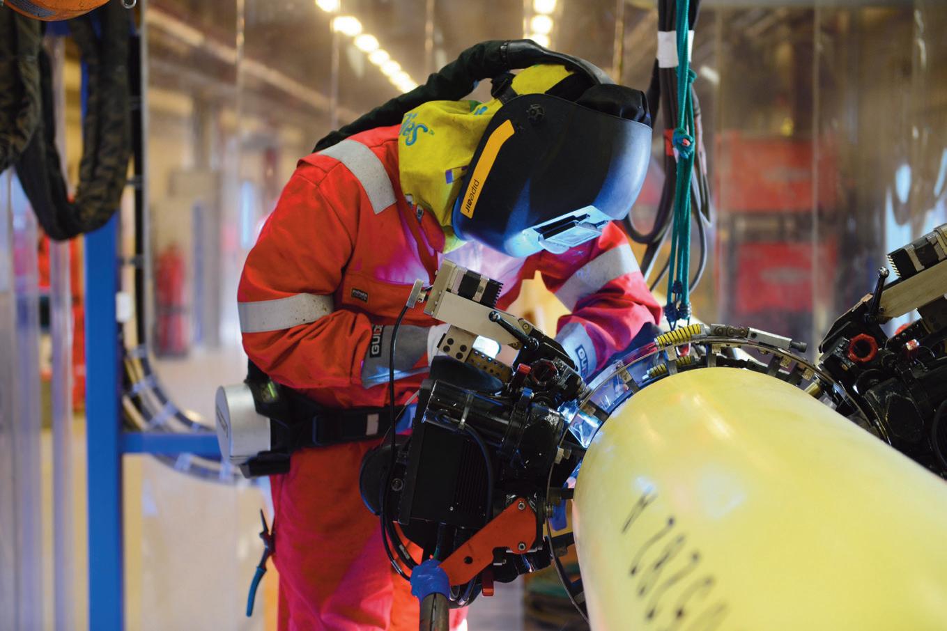
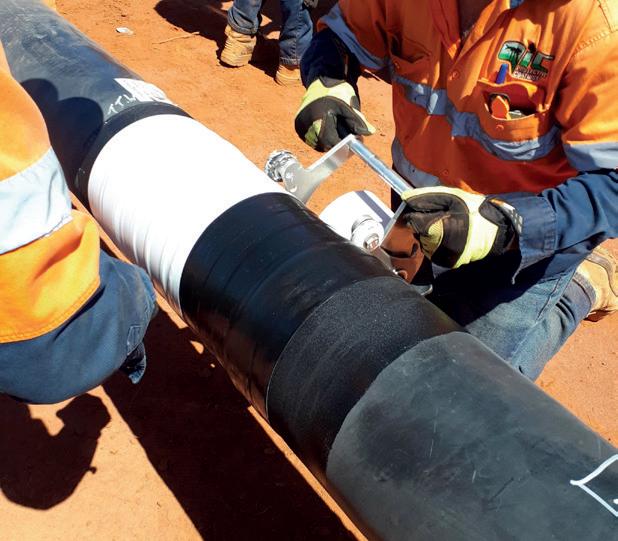
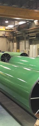
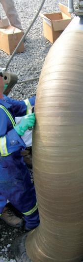
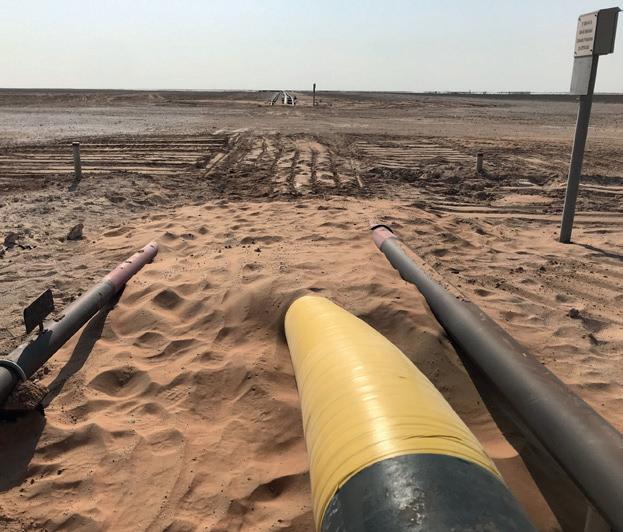
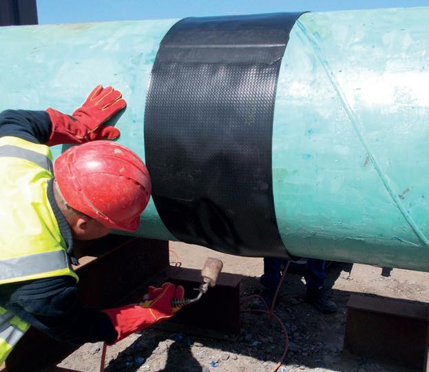
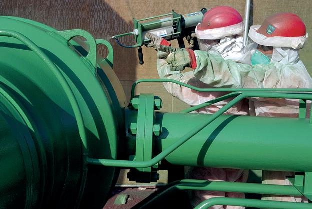
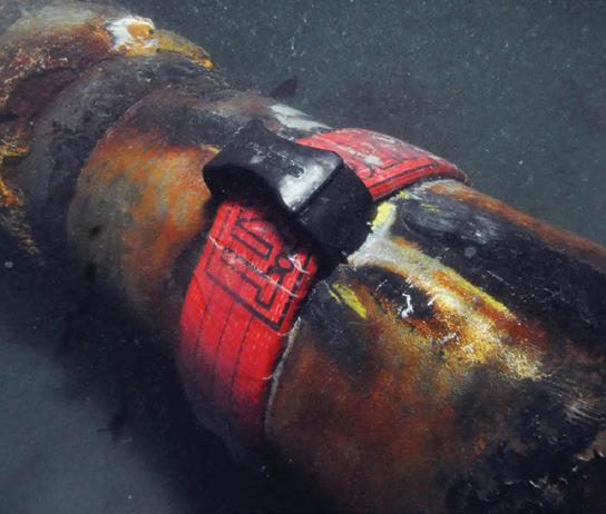
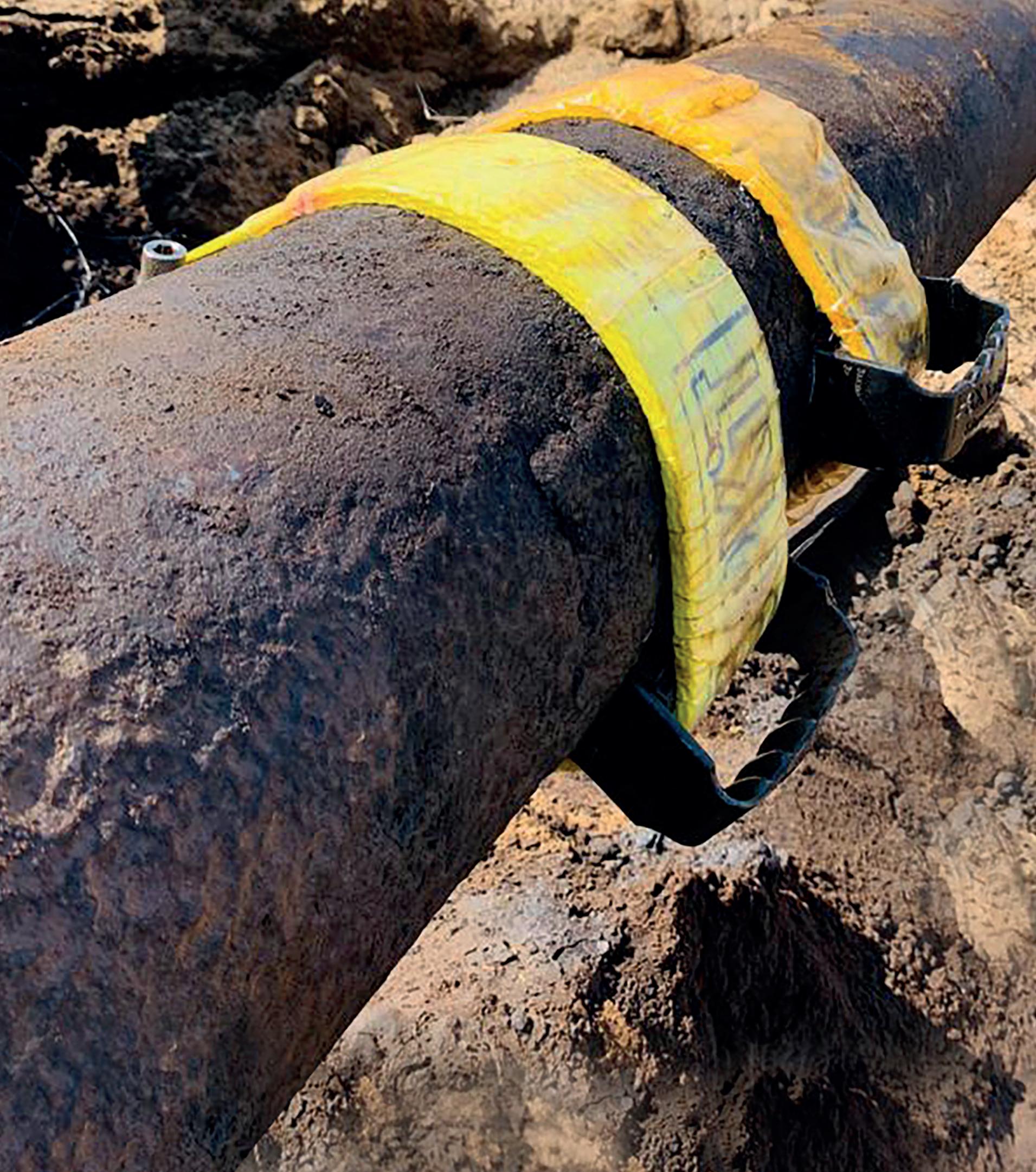
For over 30 years, 3X ENGINEERING (3X) has been one of the world leading companies specialising in pipeline maintenance using composite technology. Developer, manufacturer, seller and installer of our products, 3X offer to our clients a complete integrated service. From our head offices in Monaco, we operate worldwide, in any environment (onshore, offshore and subsea), thanks to our large qualified distribution network of over 60 partners. For more information, visit www.3xeng.com.

ISSN 14727390 Member of ABC Audit Bureau of Circulations ON THIS MONTH'S COVER Reader enquiries [www.worldpipelines.com]
Copyright© Palladian Publications Ltd 2023. All rights reserved. No part of this publication may be reproduced, stored in a retrieval system, or transmitted in any form or by any means, electronic, mechanical, photocopying, recording or otherwise, without the prior permission of the copyright owner. All views expressed in this journal are those of the respective contributors and are not necessarily the opinions of the publisher, neither do the publishers endorse any of the claims made in the articles or the advertisements. Printed in the UK. WORLD PIPELINES | VOLUME 23 | NUMBER 4 | APRIL 2023
31
43
CBP006075
21 ® Volume 23 Number 4 April 2023
PAGE 25
61. Leading the way in asset integrity management Garry Kidd, Managing Director, Wellube, UAE. A bout 68% of energy consumed in the US comes from through pipelines. Although these sources fuel our transportation, industrial, residential, and commercial needs, they like other energy sources present potential injuries occur each year, while government, industry, and public leaders urge us to do more to prevent these tragic events. Homendy, encourages us to “fearlessly pursue zero” as our only goal: zero deaths from pipeline operations. We know that be taken to turn this ambitious goal into reality? Compliance with minimum federal safety Let’s first consider the regulatory framework that’s already in place. Congress charged the US Department of Transportation’s Pipeline and Hazardous Materials Safety Administration pipeline transportation and pipeline facilities to provide “adequate protection against risks to life and property”. Before that its benefits justify its costs. This means that compliance with the minimum safety standards necessary but may not be sufficient to eliminate the potential for fatalities and
• Increase productivity
• Increase quality
• Lower repair rates
• High level of support
Together, we create the most distinctive and integrated welding solutions for the construction of reliable and sustainable pipelines. As a family business, we think long term. Dedicated and continuously improving, we always challenge ourselves to go the extra mile.
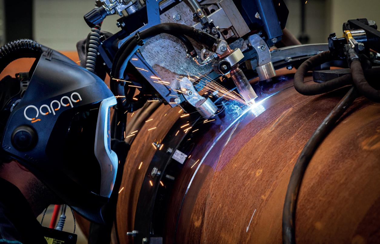
Qapqa. Joining solutions.
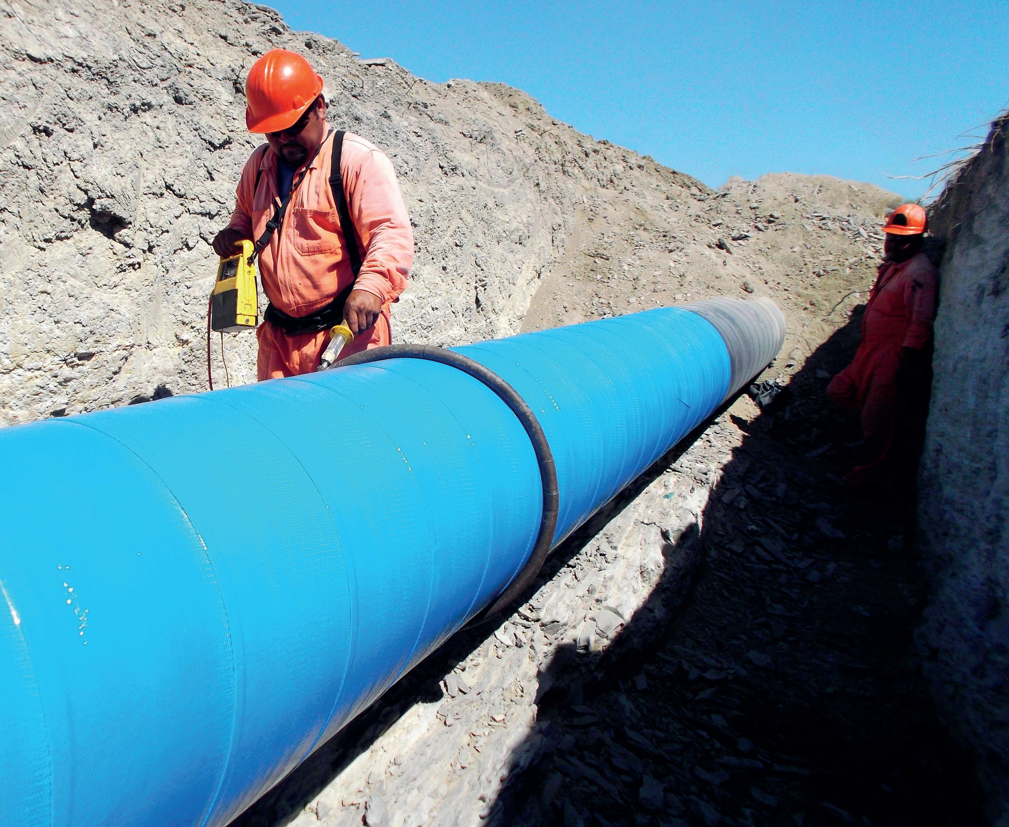
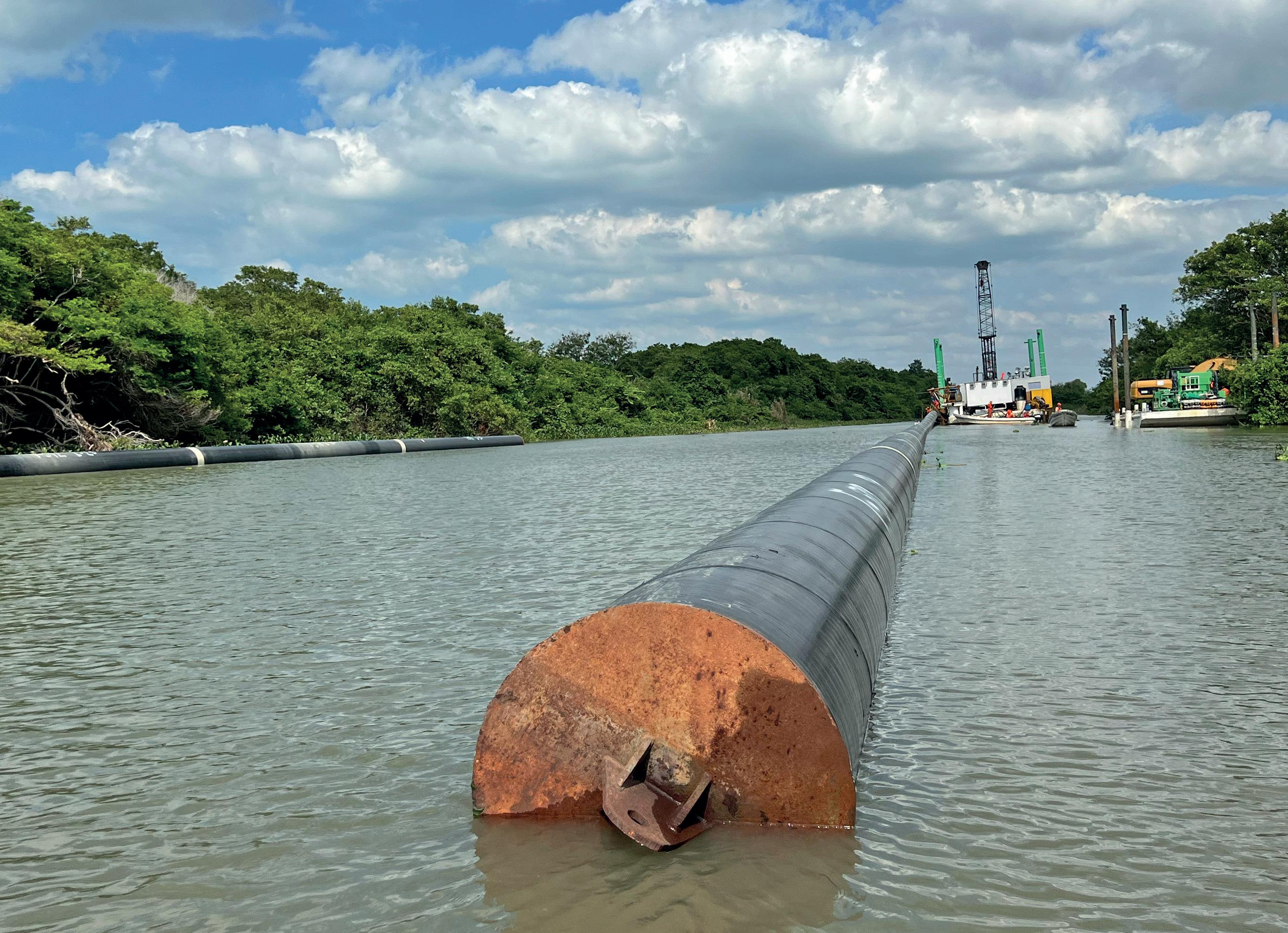 Van Oord - Mexico
EDITOR’S COMMENT
CONTACT INFORMATION
MANAGING EDITOR
James Little james.little@palladianpublications.com
EDITORIAL ASSISTANT
Sara Simper sara.simper@palladianpublications.com
SALES DIRECTOR

Rod Hardy rod.hardy@palladianpublications.com
SALES MANAGER
Chris Lethbridge chris.lethbridge@palladianpublications.com
SALES EXECUTIVE
Daniel Farr daniel.farr@palladianpublications.com
PRODUCTION MANAGER
Calli Fabian calli.fabian@palladianpublications.com
EVENTS MANAGER
Louise Cameron louise.cameron@palladianpublications.com
DIGITAL EVENTS COORDINATOR
Stirling Viljoen stirling.viljoen@palladianpublications.com
DIGITAL CONTENT ASSISTANT
Merili Jurivete merili.jurivete@palladianpublications.com
DIGITAL ADMINISTRATOR
Leah Jones leah.jones@palladianpublications.com
ADMINISTRATION MANAGER
Laura White laura.white@palladianpublications.com
Palladian Publications Ltd, 15 South Street, Farnham, Surrey, GU9 7QU, UK
Tel: +44 (0) 1252 718 999
Website: www.worldpipelines.com
Email: enquiries@worldpipelines.com
Annual subscription £60 UK including postage/£75 overseas (postage airmail). Special two year discounted rate: £96 UK including postage/£120 overseas (postage airmail). Claims for non receipt of issues must be made within three months of publication of the issue or they will not be honoured without charge.
Applicable only to USA & Canada:
World Pipelines (ISSN No: 1472-7390, USPS No: 020-988) is published monthly by Palladian Publications Ltd, GBR and distributed in the USA by Asendia USA, 17B S Middlesex Ave, Monroe NJ 08831. Periodicals postage paid New Brunswick, NJ and additional mailing offices. POSTMASTER: send address changes to World Pipelines, 701C Ashland Ave, Folcroft PA 19032
The US Department of Transport’s Pipeline and Hazardous Materials Safety Administration (PHMSA) has announced a strategic partnership with NASCAR, to increase awareness of the ‘Call 811’ initiative. Members of the American public are urged to call 811 or visit call811.com two days before digging on their property. The service provides homeowners, contractors and other professionals with information about the location of underground utilities. April was declared Safe Digging Month in the US in 2007, and every year the month continues to see increased focus on safety and preventing damage.
Under the NASCAR partnership, ‘Call 811’ will be displayed on NASCAR vehicles, fire and pit crew suits in more than 30 races during the 2023 season of the NASCAR Xfinity Series. The National Volunteer Fire Council is also promoting free excavation damage incident training resources to first responders, via a 30 second streaming advert on Spotify.
“Incidents caused by unsafe digging put workers, the public, and first responders at risk – that’s why we’re partnering with NASCAR and states from across the country to raise the public’s awareness about this important safety issue,” said PHMSA Deputy Administrator, Tristan Brown.
Visibility is an important part of this ongoing safety campaign, and it’s as important as ever to push the 811 message: the most recent version of the Common Ground Alliance’s Damage Information Reporting Tool (DIRT) report identified more than 192 000 damages to underground facilities caused by unsafe digging in the USA in 2021.
In this month’s issue of World Pipelines, our keynote feature focuses on compliance and standards, with safety goals in mind. On p.8, Sara Lyons, Pipeline Accident Investigator from the National Transportation Safety Board (NTSB), argues that compliance with minimum federal safety standards is not enough to eliminate the potential for fatalities and injuries. To achieve its safety goals, she goes on, the pipeline industry must thoroughly study lower consequence events and learn from past mistakes. The article offers valuable insight into the NTSB’s pipeline safety investigation work, and how it (along with PHMSA, the state and pipeline operators) can push for zero deaths from pipeline operations. Read the piece for more details on the Farmersville, Texas accident (2021) in which an explosion took place in a pig launcher; the Danville, Kentucky incident (2019) in which a 30 in. pipeline ruptured; and the Merrimack Valley, Massachusetts overpressurisation accident (2018). By careful examination and documentation of these failures, and others like them, Lyons is convinced that the industry can succeed in eliminating serious accidents.
Also in this issue, Plastometrex considers new ways to meet Mega Rule legislation when it comes to material verification requirements (p.15); Stark Solutions gets technical about product development on quick opening closures (p.21); and the American Society for Nondestructive Testing (ASNT) writes about the importance of routine pipeline inspection, the need for innovative NDT techniques and how the standards for condition assessment of pipelines are evolving.
SENIOR EDITOR Elizabeth Corner elizabeth.corner@palladianpublications.com
The welding and coating experts you can trust

Ensure the efficient, on-time delivery of your onshore and offshore projects with CRC Evans’ market-leading welding and coating services, technologies and integrated solutions, and extensive fleet of pipeline equipment
americas Europe Middle East Africa Asia Pacific crcevans.com enquiries@crce.com @crcevansglobal CONNECT WITH CRC EVANS
Power of Siberia 2 update: pipeline delay following Russia-China talks
Russian President, Vladimir Putin and Chinese leader, Xi Jinping met in Moscow for two days of talks in March, during which they discussed the Power of Siberia 2 pipeline project, to deliver gas to China via Mongolia.
Ahead of the meeting, Putin said Russia, China and Mongolia had completed “all agreements” on finishing the pipeline to ship Russian gas to China, and that Russia will deliver at least 98 billion m3 of gas to China by 2030, although a subsequent Russian statement said pipeline details still need to be resolved.
Russia proposed the route years ago but the plan has gained urgency as Moscow looks to Beijing to replace Europe as its major gas customer.
The Chinese and Russian leaders’ talks did not yield decisive agreements on economic issues important to helping Moscow weather western sanctions. Putin’s main goal during the Chinese leader’s stay was to secure agreement for his planned Power of
Siberia 2 gas pipeline set to supply China via Mongolia. Xi remained silent on the topic. A lengthy joint statement said only that Russia and China would “make efforts to advance work on studying and agreeing” plans to build the pipeline.
The proposed pipeline would bring gas from the huge Yamal peninsula reserves in west Siberia to China, the world’s top energy consumer and a growing gas consumer.
The first Power of Siberia pipeline runs for 3000 km (1865 miles) through Siberia and into China’s northeastern Heilongjiang province.
The new route would cut through eastern Mongolia and into northern China.
Gazprom began a feasibility study on the project in 2020, and has aimed to start delivering gas by 2030.
The 2600 km pipeline could carry 50 billion m3/y of gas, slightly less than the now defunct Nord Stream 1 pipeline linking Russia to Germany under the Baltic Sea.
Edison decision on EastMed pipeline due by end of the year
Energy group Edison plans to take the final investment decision (FID) on a proposed pipeline to deliver east Mediterranean gas to European markets by the end of this year, the Italian project developer told news source Reuters.
The EastMed-Poseidon pipeline, which would initially connect several gas fields offshore Israel to Italy, and have an annual capacity of 10 billion m3 of gas, could be ready by 2027, Edison said.
The project, supported by Israel, Cyprus and Greece, would guarantee alternative supplies for Europe, which is weaning itself off of Russian piped gas. In addition, it would better connect Cyprus to its EU partners.
For these reasons, the European Commission could be interested in partly funding the project, whose cost is estimated at around €6 billion (US$6.4 billion), Edison said.
“We expect to take the FID by the end of this year. With a
Transgaz to build pipeline for Black Sea gas
Romania’s gas pipeline operator Transgaz is to build a new pipeline worth an estimated €500 million (US$529.30 million) designed to bring offshore Black Sea gas to the national grid once the two gas producers make a final investment decision (FID), Prime Minister, Nicolae Ciuca said on 16 March.
Romanian oil and gas group OMV Petrom, majority controlled by Austria’s OMV and state-owned Romgaz, is expected to make a final decision to invest in a long-awaited offshore project by mid-2023. The project is estimated to cost €4 billion and produce at least 6 billion m3/yr.
“We are readying the transport infrastructure (for the project),” the Prime Minister said. “Transgaz has signed the contract, with [...] works set to start after a final investment
FID in 2023, the project would be realised by 2027,” Fabrizio Mattana, Edison’s Executive Vice President for gas assets, told Reuters.
Italy’s Edison, a subsidiary of France’s EDF, and Greece’s DEPA International Projects, are promoting the project through their joint venture IGI Poseidon. Last year, they received independent positive assessments over the feasibility of the pipeline, which would be 2000 km (1243 miles) long, with at least 800 km offshore.
The pipeline would be fed by Israeli gas fields already in production and others under development. These are Leviathan, Tamar and also the Tanin and Karish fields that have additional reserves to be developed, Mattana said.
These fields produce around 28 billion m3/yr, with about a third exported to Egypt and Jordan. Production is expected to climb in the coming years as current projects are expanded and any discoveries are brought online.
decision is made.”
The Neptun Deep block is expected to have a production capacity of at least six billion m3/yr of gas.
The 308.3 km gas pipeline will be built as part of the ‘Gas transmission pipeline Black Sea – Podisor’ project.
The transmission pipeline Tuzla-Podisor will connect the available gas in the Black Sea to the BRUA corridor.
Transgaz said in a statement: “The implementation of a transmission infrastructure allowing for the connection of the gas available at the Black Sea shore to the BRUA corridor is a project of vital importance for Romania, in terms of energy security, and the conclusion of these gas transmission contracts represents the pre-requisite for the development of this infrastructure.”
APRIL 2023 / World Pipelines 5
WORLD NEWS
CONTRACT NEWS
ICR Integrity announces major contract win with Petrofac
Perma-Pipe announces Gulf of Mexico project award
20 April 2023
Global Hydrogen Conference 2023 Online www.accelevents.com/e/ghc2023
1 - 4 May 2023
Offshore Technology Conference 2023
Houston, USA 2023.otcnet.org
8 - 11 May 2023
Pipeline Technology Conference (ptc) Berlin, Germany www.pipeline-conference.com
9 - 11 May 2023
Canada Gas & LNG Exhibition and Conference
Vancouver, Canada www.canadagaslng.com
13 -15 June 2023
Global Energy Show 2023 Calgary, Canada www.globalenergyshow.com
5 - 8 September 2023
Gastech 2023 Singapore www.gastechevent.com
21 - 22 September 2023
Subsea Pipeline Technology Congress (SPT 2023)
London, UK sptcongress.com
2 - 5 October 2023
ADIPEC 2023
Abu Dhabi, UAE www.adipec.com
ICR Integrity has announced the re-award of its master service agreement (MSA) with Petrofac valued at over £1 million per annum following a successful tender exercise.
The MSA was initially awarded in 2019, as a result of ICR’s well-established partnership with Petrofac delivering specialist repair and inspection services for all duty holder assets in the North and Southern North Sea, with the purpose of strategically aligning the various ICR services delivered to Petrofac under a single cross-asset agreement.
ICR will continue to provide Petrofac with innovative repair solutions including: TechnowrapTM engineered composite and clamp repairs, QuickflangeTM weldless connection solutions, chemical injection pump skids, corrosion inspection services and drone inspection through its SkyFuturesTM team.
Overall O&G contract value up by 27%
The oil and gas industry contract value has seen a significant q/q increase of 27% in 4Q22, according to GlobalData.
GlobalData’s latest report, ‘Oil and Gas Industry Contracts Analytics by Sector (Upstream, Midstream and Downstream), Region, Planned and Awarded Contracts and Top Contractors, Q4 2022’, shows that the overall contract value increased from US$47.38 billion in 3Q22 to US$60.36 billion in 4Q22. Contract volume, however, decreased from 1673 in 3Q22 to 1443 in 4Q22.
Pritam Kad, Oil and Gas Analyst at GlobalData, comments: “The key drivers for the value momentum were Saipem’s US$4.5 billion contract from Qatargas for the EPC of the North Field Production Sustainability Natural Gas Compression Complex Project, offshore north-east coast of Qatar; and ADNOC’s US$4 billion framework with ADNOC Drilling, Schlumberger, and Haliburton for the integrated drilling fluids services (IDFS) for projects in the UAE.”
Operations and maintenance (O&M) represented 55% of the total contracts in 4Q22, followed by procurement with 19%, and contracts with multiple scopes, such as construction, design and engineering, installation, O&M, and procurement accounted for 13%.
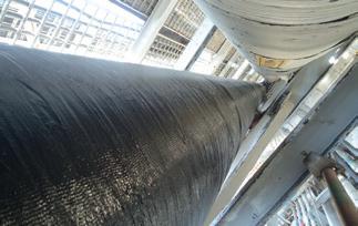
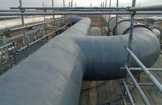
Perma-Pipe International Holdings, Inc. has been awarded a contract in excess of US$9 million. The contract is for the Winterfell Project in the US Gulf of Mexico for Beacon Offshore Energy LLC. The project will be executed at Perma-Pipe’s facility in the Port of Iberia, Louisiana in the latter part of 2023 and will be completed before the end of the year.
The newly awarded project involves the application of PermaPipe’s FLOW-THERM® subsea wet insulation to the flowline that forms a part of Beacon’s Winterfell Project, located in the US Gulf of Mexico at a water depth of approximately 5800 ft (1600 m).
ON OUR WEBSITE
• Object found next to Nord Stream pipeline
• Colombia’s Ecopetrol criticises new attacks on oil pipeline
• Oil flow halts in BatmanDörtyol pipeline due to leak
• Xage selected by Kinder Morgan to cyber-harden critical infrastructure
• Reaction to IPCC report
• AMPP names new CEO
Follow us on LinkedIn to read more about the articles linkedin.com/showcase/worldpipelines
6 World Pipelines / APRIL 2023
EVENTS DIARY
PROTECTIVE OUTERWRAPS
HEAT SHRINKABLE SLEEVES
SOIL-TO-AIR INTERFACE
INTERNAL
DENSO™ are leaders in corrosion prevention and sealing technology. With 140 years’ service to industry, our mainline and field joint coating solutions offer reliable and cost effective protection for buried pipelines worldwide.


United Kingdom, UAE & India
USA & Canada
Australia & New Zealand
Republic of South Africa
FOR CORROSION PREVENTION
www.denso.net

www.densona.com
www.densoaustralia.com.au
www.denso.co.za
LIQUID EPOXY COATINGS
PETROLATUM TAPE WRAP SYSTEMS
BUTYL TAPE WRAP SYSTEMS
PIPE LININGS
BITUMEN TAPE WRAP SYSTEMS
A MEMBER OF WINN & COALES INTERNATIONAL
VISCO-ELASTIC COATINGS
To achieve our safety goals, we need to thoroughly study lower consequence events to learn from past mistakes, says Sara Lyons, Pipeline Accident Investigator, National Transportation Safety Board (NTSB), USA.
bout 68% of energy consumed in the US comes from petroleum and natural gas, which are often transported through pipelines.1 Although these sources fuel our transportation, industrial, residential, and commercial needs, they – like other energy sources – present potential hazards to our health, safety, and environment. Fatalities and injuries occur each year, while government, industry, and public leaders urge us to do more to prevent these tragic events.
Given the NTSB’s long history of investigating catastrophic pipeline accidents, it’s not surprising that NTSB Chair, Jennifer Homendy, encourages us to “fearlessly pursue zero” as our only goal: zero deaths from pipeline operations.2 We know that these accidents are preventable, but what practical steps can be taken to turn this ambitious goal into a reality?
Compliance with minimum federal safety standards is not enough

Let’s first consider the regulatory framework that’s already in place. Congress charged the US Department of Transportation’s Pipeline and Hazardous Materials Safety Administration (PHMSA) with prescribing minimum safety standards for pipeline transportation and pipeline facilities to provide “adequate protection against risks to life and property”. Before enacting a safety standard, PHMSA typically must determine that its benefits justify its costs. This means that compliance with the minimum safety standards is necessary but may not be sufficient to eliminate the potential for fatalities and
injuries. To achieve zero, the focus must extend beyond these minimum safety standards.
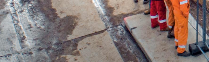
For example, in the NTSB’s investigation of an accident that occurred near Farmersville, Texas on 28 June 2021, investigators reviewed two industry guidance documents intended to help pipeline operators maintain a PHMSA-compliant operator qualification (OQ) programme.3,4 Neither document identified the task that was being performed at the time of the accident as one that was subject to PHMSA’s OQ rules. Similarly, the affected pipeline operator did not include this task in their OQ programme, relying instead on on-the-job training. Nevertheless, the NTSB determined that the operator’s procedures and training practices did not prepare workers to recognise and safely respond to abnormal operating conditions. This contributed to the severity of the accident, which took the lives of two men, leaving five surviving witnesses, two of whom were also injured.
PHMSA’s OQ rules apply to tasks that meet certain criteria, such as being “performed as a requirement of [specific PHMSA regulations]”. Industry representatives said that launching and receiving pigs did not meet this criterion. In adopting this narrow interpretation, the opportunity to fully prepare workers to safely respond to foreseeable, abnormal operating conditions was missed.
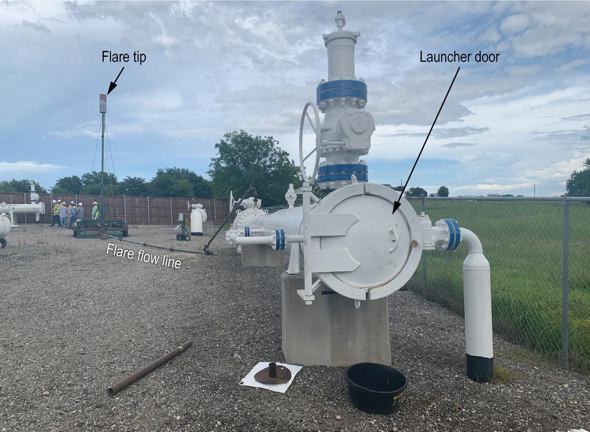
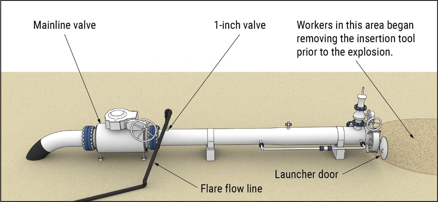
Let’s examine the circumstances of the Farmersville accident. About a week prior to the accident, workers completed the first in a series of pig loadings, when they suspected that the mainline valve was leaking because the flare did not extinguish as expected. They adjusted the valve and did not have any issues with the flare extinguishing during subsequent runs.
On the day of the accident, a worker opened a 1 in. valve that allowed natural gas to vent from the launcher to the flare tip, where it successfully ignited. As natural gas pressure in the launcher decreased and less natural gas flowed to the flare tip, the work crew observed the flame die down and extinguish.
8


9
Workers then took photos of the pig and began loading and inserting it into the launcher. An explosion in the launcher occurred before the insertion tool was completely removed. The NTSB found that a leaking mainline valve allowed natural gas to enter the launcher where it mixed with air, creating a flammable gas-air mixture that was ignited by an undetermined source.
Notably, the workers did not monitor pressure while depressurising the launcher, nor did they monitor for hazardous vapours before and during loading. These are steps recommended in another industry guidance document that was available prior to the accident, American Society of Mechanical Engineers (ASME) standard B31Q, ‘Pipeline Personnel Qualification’. Instead of focusing on minimum safety standards, ASME B31Q sought to specify requirements for identifying tasks that impact safety, such as launching and receiving pigs. ASME B31Q identified possible abnormal operating conditions, such as an unplanned escape of product from a pipeline. This is exactly what occurred in the Farmersville accident.
Although PHMSA later clarified that launching and receiving pigs is a covered task according to their regulations, the guidance that was developed from the broader lens of
minimising impacts on safety could have helped prevent this accident.5 The guidance that focused on minimum safety standards did not.
Continuous improvement of integrity management programmes
Pipeline integrity management is another critical safety programme that is used to identify, assess, and manage pipeline risks from all threats. Risk, a measure of the probability and severity of adverse events, is often estimated by answering the following questions:
) What can go wrong?
) How likely is this to happen?
) If it does happen, what are the consequences?
The first step is identifying the potential threats to pipeline integrity. All threats must be considered, including material degradation, incorrect operational procedures, and vandalism, to name a few. ASME standard B31.8S, ‘Managing System Integrity of Gas Pipelines’, considers 21 threats which are divided into nine categories and three time-related groups: time-dependent, stable, and time-independent. This ASME standard also requires that the interactive nature of threats be considered.
Risks are managed by performing integrity assessments, acting to reduce risks, and continuing to evaluate risks as they change. Integrity management programmes can be iteratively improved over time as additional information is gathered, risks are better understood, and assessment techniques are further developed. PHMSA’s minimum safety standards require pipeline operators to develop and implement integrity management programmes for pipeline segments that could affect high consequence areas.
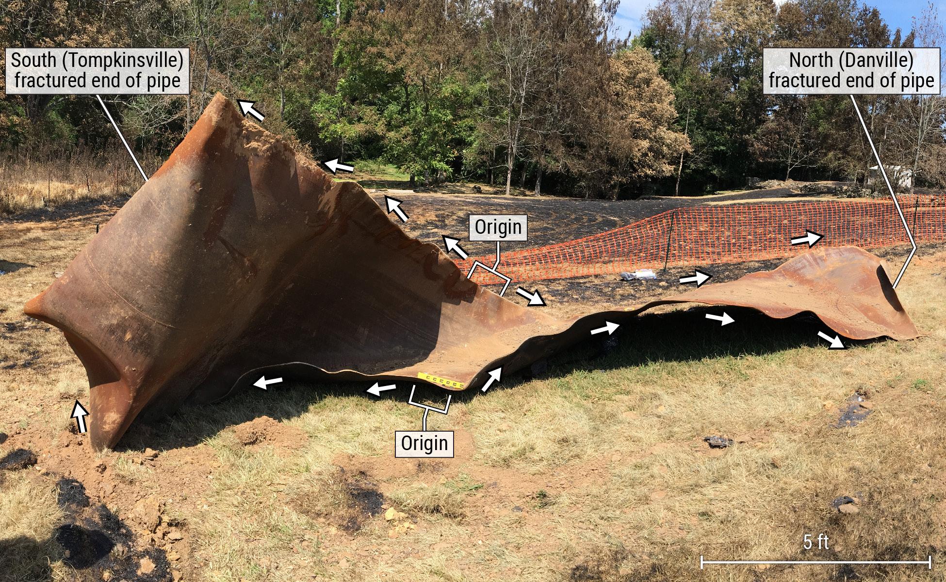
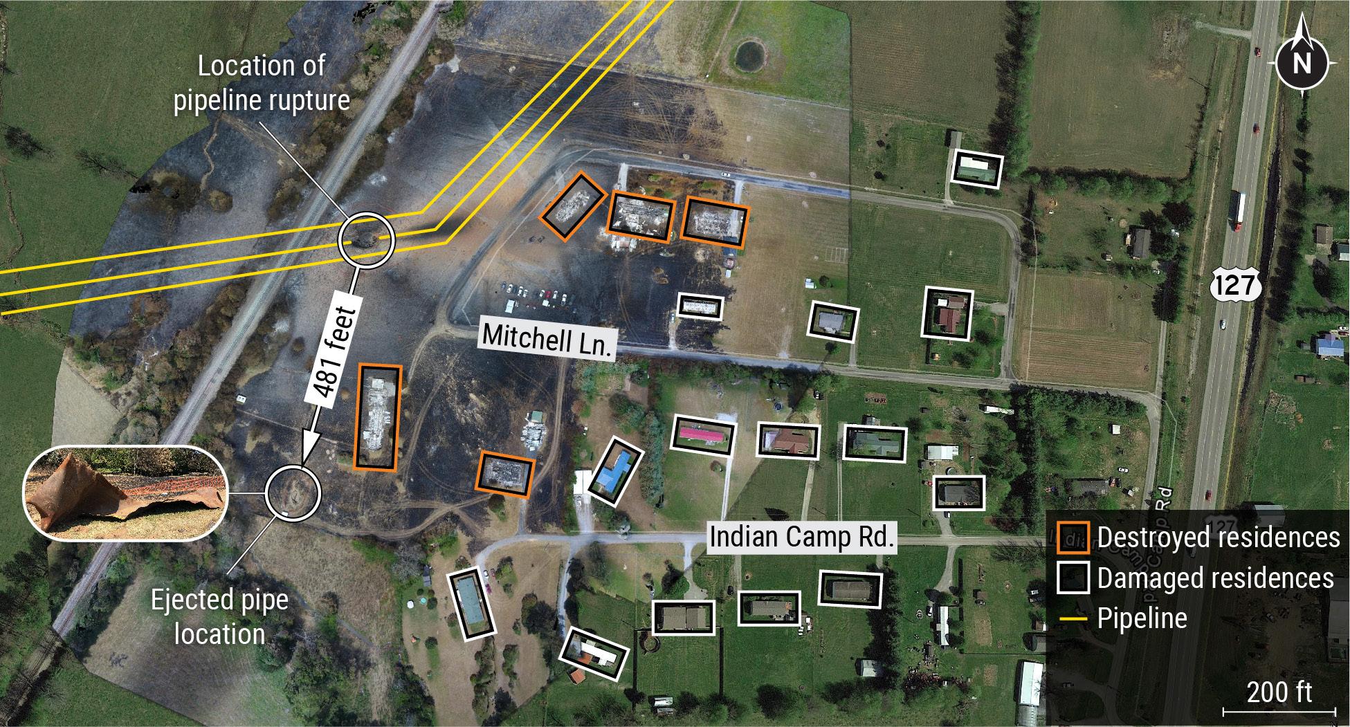
In the NTSB’s investigation of a 30 in. diameter pipeline that ruptured in Danville, Kentucky on 1 August 2019, investigators found that the fracture originated at a hard spot on the outer surface of the pipeline, which resulted from unintentional localised rapid cooling during manufacture.6 The pipe was manufactured in 1957 to standards that did not specify rejectable criteria for
April
April
October
Table 1. Overpressurisation incidents (USA).
10 World Pipelines / APRIL 2023 1960s 1970s 1980s 1990s 2000s 2010s June 1969 Gary, Indiana August 1977 El Paso, Texas January 1982 Centralia, Missouri January 1992 Chicago, Illinois June 2001 Pittsfield, Massachusetts January 2011 Fairport Harbour, Ohio
1969 Burlington, Iowa May 1978 Mansfield, Ohio September 1983 East Boston, Massachusetts
1992
Illinois
2003
New York
2018 Merrimack Valley, Massachusetts
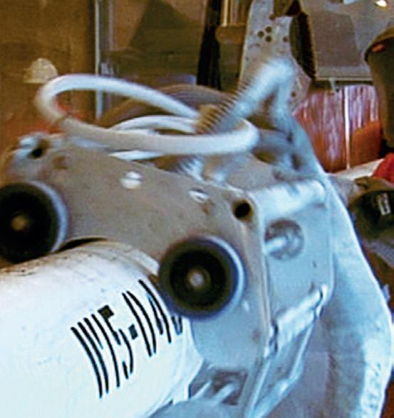
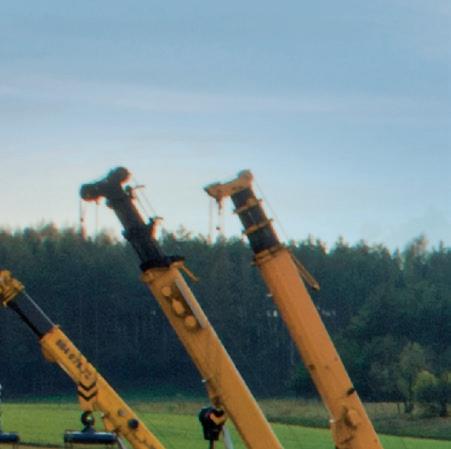
Figure 1. The pig launcher near Farmersville, Texas.
November
December
Springfield,
November
Cohoes,
September
1993
South Buffalo, Pennsylvania
2005
Boonville, Missouri
1994
Alameda, California


hard spots. Pipe of this vintage was known to have a history of hard spots. By current standards, the 5.85 x 3 in. hard spot found at the rupture location is considered a rejectable defect. Hard spots fall under the category of manufacturingrelated defect, considered a stable threat in ASME B31.8S. In 2011, an inline inspection (ILI) to identify and classify hard spots on the affected segment was completed, but none of the identified hard spots were located at the Danville, Kentucky failure origin. After this ILI, the pipeline operator no longer identified hard spots as a threat for this pipeline segment. However, the NTSB found that the Danville rupture was caused by the combination of a pre-existing hard spot, degraded coating, and ineffective cathodic protection, which resulted in hydrogen-induced cracking at the outer surface.
A 2016 study found that changes in operating conditions, such as reversal of flow direction, could intensify certain threats, including those posed by hard spots.7 The pipeline operator did not assess how a change in operating conditions from reversing the flow in 2014 affected the hard spots, missing the opportunity to improve their integrity management programme in time to prevent the Danville accident. Thus, the NTSB found that the operator’s
integrity management programme did not accurately estimate the risk from interacting threats, a contributing cause of the rupture that resulted in one fatality, six injuries, the evacuation of over 75 people, destruction of five homes, and damage to 14 other homes.
Revisiting our shared history
Getting to zero is not just about learning from the major tragedies the NTSB investigates. To achieve our safety goals, we need to thoroughly study lower consequence events to learn from past mistakes and remember what went well.
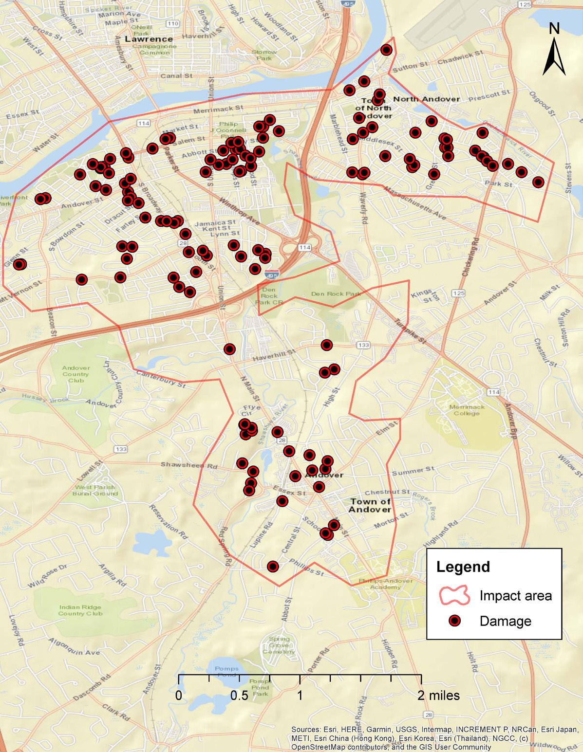
This was evident in the NTSB’s investigation of an accident that occurred in Merrimack Valley, Massachusetts on 13 September 2018.8 This accident occurred when high-pressure natural gas was released into a low-pressure natural gas distribution system. But this wasn’t the first time a low-pressure distribution system had been overpressurised.
Before the Merrimack Valley accident occurred, the NTSB had investigated seven overpressurisation accidents. Seven other overpressurisation incidents had been reported to PHMSA, making at least 14 previous incidents in the public record to learn from.
The potential catastrophic consequences of overpressurising a low-pressure system was known, and these 14 incidents could have been studied well before the Merrimack Valley accident occurred. Doing so would have revealed that they were all experienced by different operators. The affected systems typically had redundant components intended to help prevent overpressurisation accidents, such as workermonitor regulators. However, redundant components are more susceptible to failure due to a single threat, or common cause (such as flooding, lightning, or human error). Common cause failures can significantly increase safety risk because they negate the safety benefits of redundant components. They are often addressed by using different (diverse) components, such as a regulator and a relief valve.
Had this information been studied prior to the Merrimack Valley accident, safety improvements could have been made in time to prevent it. Instead, the accident devastated a community, resulting in 1 fatality, 29 injuries, damage to 131 structures, and estimated costs exceeding US$1.5 billion.
The NTSB identified organisational failures in the probable cause of the Merrimack Valley accident. Contributing to the accident, the NTSB found, was a low-pressure natural gas distribution system designed and operated without adequate overpressure protection. Adequate overpressure protection could have helped safeguard the system against human error. By
Figure 2. Diagram of pig launcher near Farmersville, Texas (Source: NTSB graphics by Christy Spangler).
12 World Pipelines / APRIL 2023
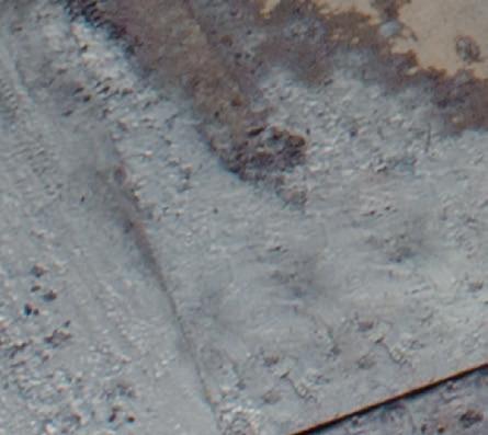
Figure 3. Ejected pipeline segment in Danville, Kentucky.
studying our shared history and revisiting these topics as more experience is gained, we can glean insights that can help us act before catastrophic accidents occur.
Pipelines are the safest way to transport hazardous materials, but there is still room for improvement. While the failure rates are low (about one serious accident occurs for each 100 000 miles of pipeline each year), this amounts to 260 deaths and 1110 injuries in the last 20 years, according to data reported to PHMSA.
The NTSB puts a lot of energy into making sure that our investigations are accurate accounts of what happened, and we provide transparency for these investigations with publicly available supporting documentation. But many incidents are investigated, not by the NTSB, but by PHMSA, state regulators, or pipeline operators. The operator-provided information contained in PHMSA’s database can be a powerful resource to guide our path to zero, especially if it is combined with other available sources, such as NTSB, PHMSA, state, and pipeline operator investigative reports. Together, we can eliminate these serious accidents.
References
1. www.eia.gov/energyexplained/us-energy-facts
2. www.ntsb.gov/Advocacy/Activities/Pages/Homendy-20230111.aspx
3. www.ntsb.gov/investigations/Pages/PLD21FR002.aspx
4. ANSI/GPTC, Guide for Gas Transmission, Distribution, and Gathering Piping Systems (2018).
5. www.phmsa.dot.gov/regulations/title49/interp/PI-22-0008
6. www.ntsb.gov/investigations/Pages/PLD19FR002.aspx
7. Muñoz, E., Rosenfeld, M. J., DTPH56-14-H-00004: Improving Models to Consider Complex Loadings, Operational Considerations, and Interactive Threats (2016).
8. www.ntsb.gov/investigations/Pages/pld18mr003.aspx
14 World Pipelines / APRIL 2023
Figure 5. Aerial view of the Danville, Kentucky, accident site.
Figure 4. Map of damaged structures in Merrimack Valley, Massachusetts.
or engineers tasked with managing multi-dimensional, data-rich, pipeline integrity management programmes and Mega Rule compliance initiatives, staying ahead of new regulations can be a daunting endeavour. Fortunately, there’s a new PMI tool in the final stages of validation testing that simplifies material verification and enables resourceful teams to collaborate more efficiently on their regulatory obligations.
Legislation – PHMSA and the Mega Rule Integrity management of pipelines is a complex issue, and global legislations exist to guarantee their safe operation. In the US, the Pipeline & Hazardous Materials Safety Administration (PHMSA), part of the Department of Transportation, sets the rules and regulations in this domain – with their most recent ‘Mega Rule’ legislation demonstrating just how critical pipeline integrity is at a national level. Such guidelines
establish standards for the design, construction, operation, and maintenance of pipelines. They might also provide guidelines for conducting integrity assessments and developing integrity management plans, as well as determining the roles and responsibilities of the various parties involved in the management of pipeline integrity.

In a move to enhance safety for onshore gas transmission pipelines, this new legislation broadens the scope of existing rules and regulations. Industry professionals well-versed in these measures will find that several additions have been included with an emphasis on ensuring maximum safety, such as additional material verification requirements and re-confirmation of maximum allowable operating pressure (MAOP).
The Mega Rule ensures that pipelines are operating safely and remain in good condition by requiring operators to implement comprehensive integrity management
15
Dr James Dean, CEO, Plastometrex, UK, introduces a novel tool for pipeline integrity management programmes and Mega Rule compliance.
programmes. These programmes assess potential risks, such as cracks or corrosion, and take corrective steps where needed, thereby ensuring optimal performance is maintained (as much as is feasibly possible) across all pipeline infrastructure.
Pipeline integrity management – methods and tools
Of course, the legislative frameworks are helpful, but the importance of pipeline integrity management is already well understood in an industry that has, historically, prioritised safety, and spent billions of dollars implementing these complex integrity management programmes. These programmes are geared towards the detection, classification,
and remediation of defects including, but not limited to, those that are listed below:
) Corrosion, or the deterioration of material due to its exposure to environments that contain, for example, water, salts, and other contaminants that can facilitate unwanted chemical reactions.
) Cracks, which can occur in pipelines due to various reasons, including manufacturing defects, applied loads (stresses), and corrosion.
) Dents, which are often present after some type of localised impact event, can weaken the pipeline and accelerate its failure.
) Weld defects that arise in many different forms during welding processes, often exacerbated by the creation of large residual stresses, and the complex evolution of unwanted microstructural features.
) Manufacturing defects that were introduced during the manufacturing process.
In addition, it’s well recognised that pipeline failures are serious incidents with potentially significant consequences that include environmental damage, injury, and, in the worst cases, fatalities. They also result in costly repairs, and significant disruption to the supply of energy, with the recent spill from the Keystone Pipeline (December 2022) being just one example. Integrity management programmes are designed to prevent these types of incidents by identifying and addressing such issues before they become hazardous, but it is an ongoing process that involves inspecting and testing the pipelines, and monitoring their condition on a regular basis. There are established tools and methods for doing so – some of the most common include:
) Visual inspection, which is considered the first line of defence in detecting defects in pipelines. It can be
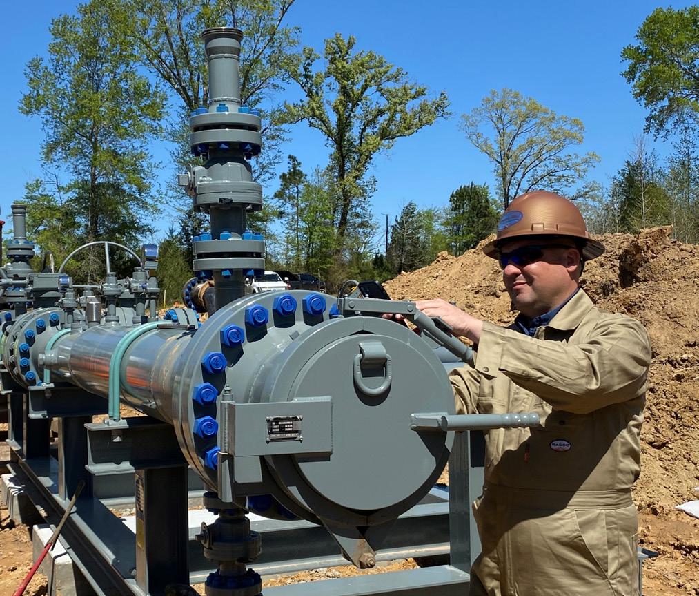
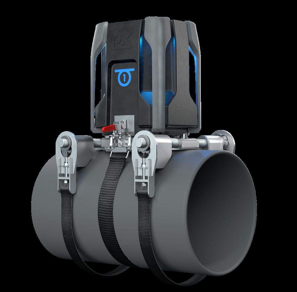 Figure 1. A render of the portable Indentation Plastometer being developed by Plastometrex for in-ditch PMI and grade determination.
16 World Pipelines / APRIL 2023
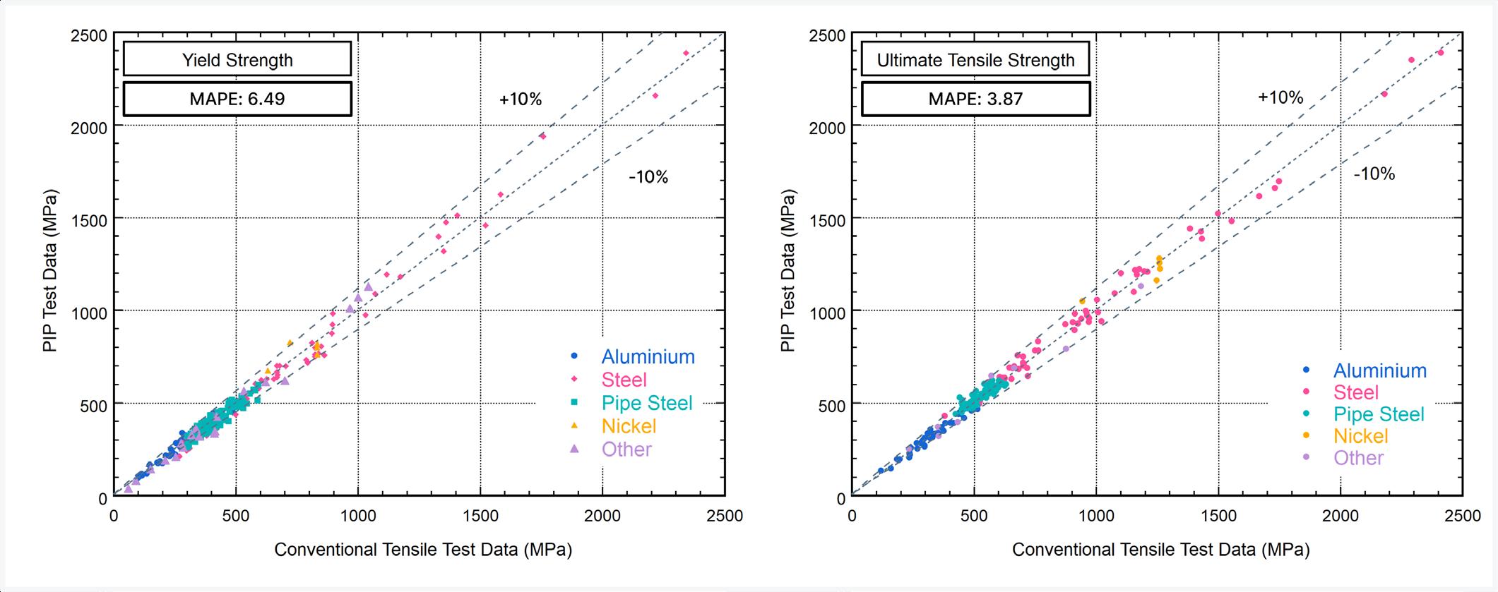
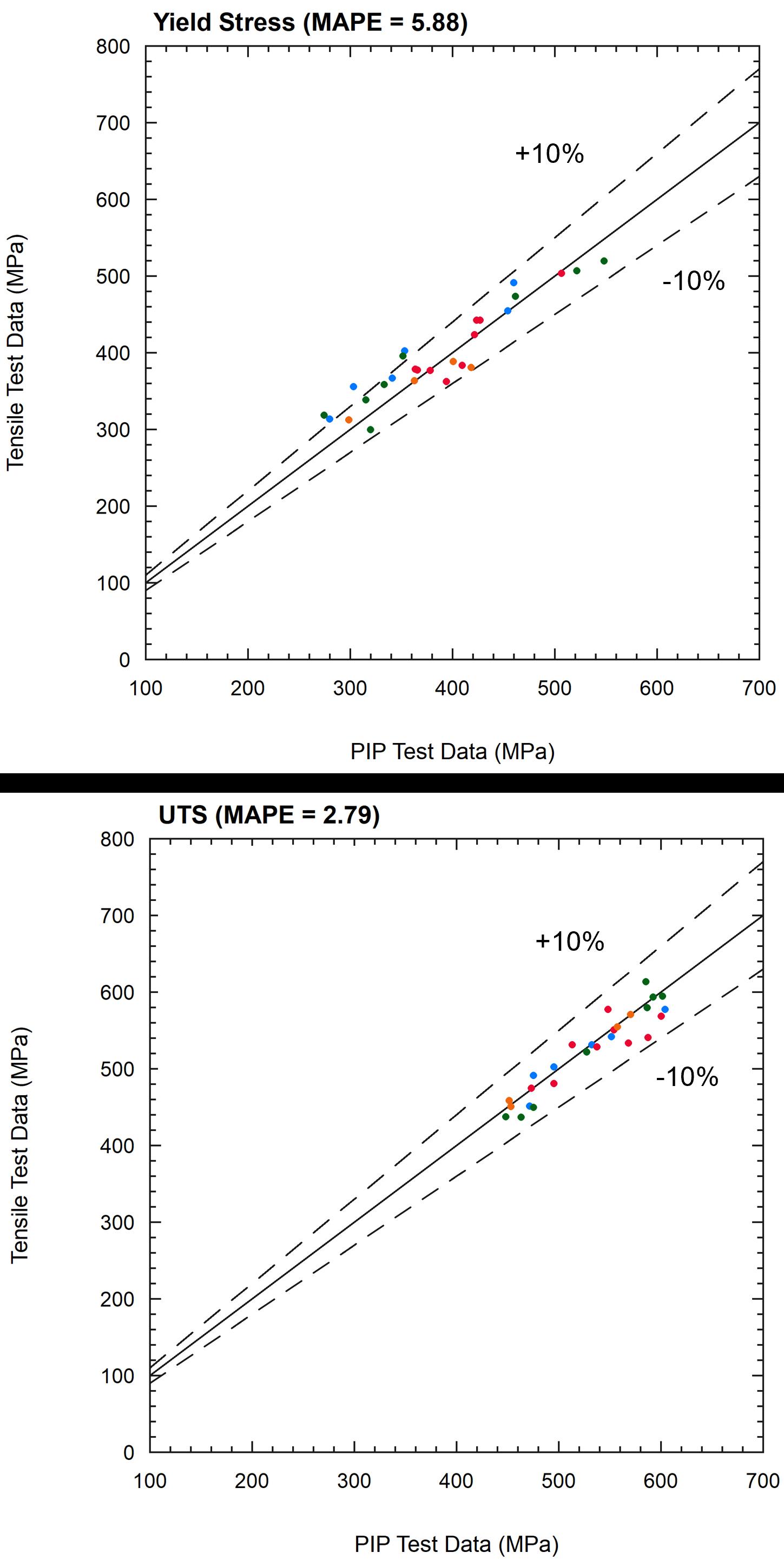
Figure 2. Unity plots for yield stress and UTS for the benchtop Indentation Plastometer including MAPE values (correct at January 2023).

BID NOW! purplewave.com BUY SELL Call us today! 866.608.9283 e Bid anytime, anywhere - 24/7 e Add items to your watchlist e Set it and forget it with MAX bid e ALL ITEMS SELL NO RESERVE! e Multiple auctions held every week e No transportation or preparation cost e We handle post auction payment/titles e ALL EQUIPMENT IS SOLD “AS IS, WHERE IS” *fees may vary based on equipment volume and value
performed manually by trained personnel using visual inspection equipment, including remotely operated vehicles (ROVs) and drones.
) Ultrasonic testing, whereby disturbances in the patterns of high-frequency sound waves are correlated to certain types of defects.
) Hydrostatic testing, which involves pressurising the pipeline with water or another liquid to check for leaks.
) Inline inspection using ‘smart pigs’ that are inserted into pipelines with instruments that can detect a variety
of defects using ultrasonic, magnetic, and radiographic techniques.
) Corrosion monitoring for detecting and monitoring the initiation and evolution of corrosion.
However, new tools are also now emerging, primarily in response to the requirements set out in Part One of the Mega Rule legislation around MAOP reconfirmation and material verification. In both cases it is necessary to measure the yield and/or tensile strength of the metal (steel) pipelines. The MAOP, for example, is determined from a calculation involving the yield strength.
Satisfying material verification requirements –a new way
One of these new tools is the portable Indentation Plastometer (Figure 1) from Plastometrex. This is a device for in-ditch measurement of yield and tensile strength to support positive material identification (PMI) and pipe grade determination. The portable device is a derivative of the company’s current flagship product, which is a benchtop Indentation Plastometer that was released commercially in January 2021. The benchtop Indentation Plastometer performs a ‘PIP’ test, which is simply an indention test that is conducted in much the same way that a hardness test is.
The main difference between a PIP test and a hardness test is that PIP test data are used to calculate metal stressstrain curves (not hardness numbers), thereby capturing important strength parameters such as the 0.2% proof stress and the stress at 0.5% elongation under load. To do this, the device measures the full shape of the indent using an optical profilometer (which takes just a few seconds) and passes this data through a proprietary software package that combines an accelerated inverse finite element analysis with optimisation algorithms to derive stress-strain curves.
The underlying scientific methodology is already proven, having been developed by former University of Cambridge Scientists, and validated by some of the world’s largest technology companies and most prestigious universities. Comparison data for the benchtop Indentation Plastometer are shown in Figure 2. A common metric for assessing the level of agreement between the PIP test data and conventional tensile test data is the mean absolute percentage error (MAPE). MAPE values for the benchtop Indentation Plastometer are provided in the figure.
The portable Indentation Plastometer uses the same scientific approach as the benchtop Indentation Plastometer, albeit deployed in a different (portable) configuration (Figure 1). Industry representatives are now asking, justifiably, for validation data for the portable device that is equivalent to what is presented in Figure 2, not least because such data exists for competing technologies already operating in the PMI space. Data for those technologies were acquired during a Pipeline Research Council International (PRCI) funded project which concluded in 2018 (report number PR-335-173816), and it is evidently clear that the Plastometrex solution for in-ditch PMI should perform
18 World Pipelines / APRIL 2023
Figure 3. Unity plots for yield stress and UTS for the portable Indentation Plastometer including MAPE values (correct at January 2023 and not yet subject to independent review).

comparably to (or better than) those technologies if it is to be successful commercially.

Validation work


The necessary validation testing project for the portable Indentation Plastometer is now well underway, with support and/or contributions from TC Energy, PG&E, ROSEN, ADV Integrity, the Integrity Assessment Group, the PRCI, RSI Pipeline Solutions, Blade Energy, and Structural Integrity Associates. The objective of the project is to test almost 200 pipeline samples, and to compare portable PIP test results with conventional tensile test results (which have been tested in accordance with the specifications laid out in API 5L).
The project started in January 2023 and some early results are presented in Figure 3, where the MAPE figures
are better than those of the two competing technologies when compared with data from the PRCI report of 2018. However, at the time of writing, the validation project is several months from completion, and the MAPE numbers for the portable Indentation Plastometer will inevitably change, so final judgement on the accuracy of the tool is currently being reserved. Nevertheless, the early signs are encouraging, and confirmation of accuracy levels will undoubtedly help as the company moves to commercialise the technology later this year, but there are other characteristics of the device that are expected to strengthen the case for its inclusion in integrity management programmes. For example, the system is modular, requiring only one minimally trained technician to operate the device. This is likely to be an advantage as owner/operators and service providers seek to scale their teams to satisfy the enormous testing demand that has been created by the Mega Rule legislation. In addition, a software wizard guides users through the testing process in an automated way, minimising the scope for user error, and a full quadrant can be tested in under 30 minutes.


Importantly, full strength data are available immediately and there is no requirement for the data to be finessed or in some way augmented offsite (which is a characteristic of some PMI tools). Finally, the device is linked to a cloud-based digital platform called PLXUS, which automatically stores the testing data in TVC-compliant form. This capability also enables engineering teams that are situated away from the dig to provide remote assistance to colleagues that are in-the-ditch, thereby enabling real-time decisionmaking based on real-time data. These attributes are already generating interest and excitement amongst industry representatives ahead of the commercial launch later this year.
The validation project is expected to conclude in the summer of 2023, with preorders (subject to successful validation) being taken now.
s a manufacturer whose products are used in the oil and gas industry, it is Stark’s professional duty to ensure that the products manufactured comply with various governmental organisations. Businesses, or their contracted third-party representatives, can be expected to want proof that the products they purchase fulfil their requirements of compliance with more than just a simple Certificate of Conformance. Furthermore, some companies have created their own additional specifications, beyond governmental or industry requirements, to confirm their operation or installation meets these additional standards.
Standards and requirements

Operating in North America, it is typical to see American Society of Mechanical Engineers’ (ASME) rules and requirements for oil and gas products. From the simple (but lengthy) pipeline standards to the well-known flange standards, to the ever-present pressure vessel standards, product design is a study in not running afoul of the various requirements while still fitting in all the features and benefits that these product users have come to expect. Quick opening closures are no different than other manufactured products in that regard. Quick opening closures must be capable of withstanding internal and external pressures, having sometimes intricately
moving components to provide entry and access inside the product, and provide repeatable, dependable operation in a variety of services and climates. Each component must meet the material requirements, pressure minimum, structural needs, and operator usability requirements. Proof of compliance is not only requested in the form of a document but is also pursued by the use of third-party companies whose job is to pore over the design and verify that they, too, can confirm the product is acceptable based on the specifications laid out.
Through years of operational expertise and a not-toosmall amount of trial and error, companies with a vested interest in the continued operation of their assets have written their own requirements for products or systems. These often take the form of company or projectspecific standards. Through these standards, a product that may already comply with the requirements set forth by governmental standards will need to meet additional design criteria. These standards can take on a variety of different shapes. The most common tend to add slightly more requirements to existing rules. It is common to see: material chemistry ranges being stricter to help meet welding procedures; higher than normally required physical properties of materials; material matching multiple certifications; material going through additional finishing processes to increase
21
By working with the end user, product designs can be offered to meet a wide variety of specifications, thereby streamlining project acceptance, says Morgan Sledd, Stark Solutions, USA.
performance in specific environments; as well as sacrificial material undergoing further testing.
A product for each project
Occasionally a specific project will present unique challenges to a product. When this occurs, the project specifications can cause a minor addition, or a major overhaul to meet the needs. Some jobs require high temperature operational capability, such that material strength becomes a concern. Some jobs require higher performance materials such as duplex or super duplex stainless steels, for their corrosion resistance and strength at higher temperatures. Some applications are known to cause such problems that special alloys are used in the sealing areas to prevent material attack in those critical areas, but the rest of the unit is allowed to degrade, within the scope of the project of course. The addition of materials like stainless steel, Inconel or Monel can greatly extend the life of the areas it is added to, prolonging the life of the product.
Stark Solutions, located north of Houston, Texas, has positioned itself to be able to provide product meeting and exceeding requested specifications. Through Stark’s proximity to the vast array of oil and gas suppliers in the greater Houston area, as well as strategic partnerships with leading suppliers, Stark offer products that ensure industry leading companies will have success in their projects. The onsite engineering department works with end users and suppliers both to guarantee compliance to specifications and project design goals as well as provide proof of compliance in the form of test results, calculations, or 3D analysis. Due to the variety of job specific demands, Stark Solutions manufactures quick opening closures in the three following styles.
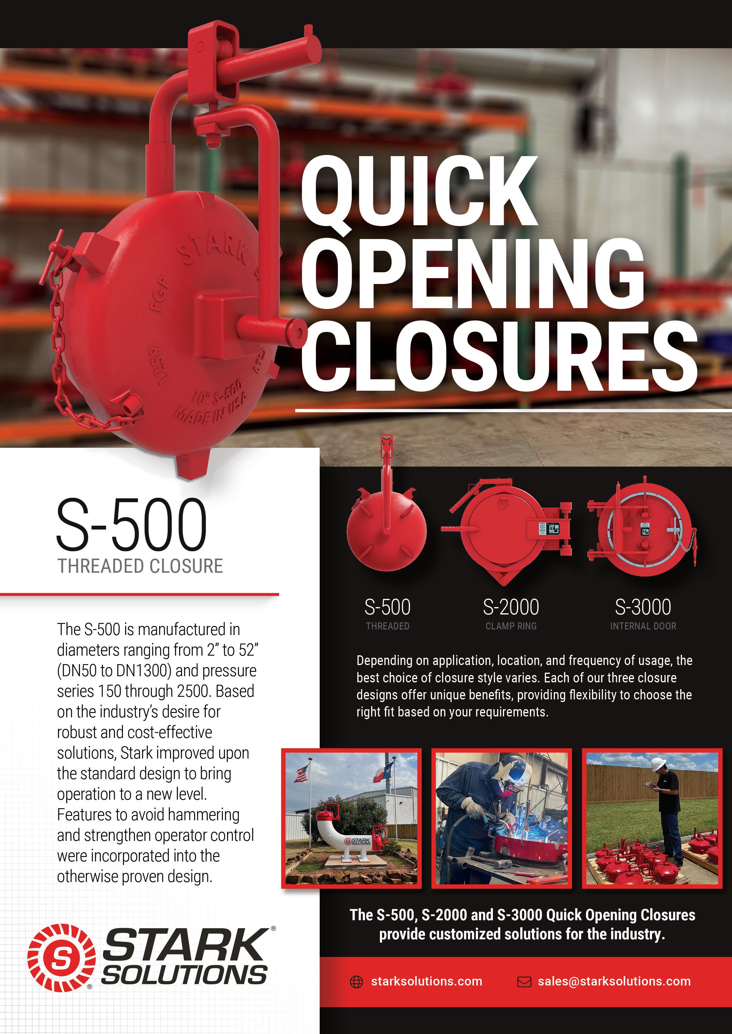
S-500
The S-500 is a threaded quick opening closure, which is Stark’s most economical option. This closure is useful for smaller applications including sampling lines, vessel blowdown caps or vessel sump drains, or for larger applications with less frequent usage, like filter separators, and launchers and receivers. The S-500 line is offered in range from 2 - 52 in. and comes in a variety of carbon steels as standard options. These are compatible with most North
American code requirements. An array of upgrades are available, including additional ports in a variety of NPT sizes, provided by the manufacturer. Many see having the manufacturer provide these additional access points a benefit, as they can be part of the design that is certified. For more exacting applications, alternative materials such as stainless steels can be entertained, and performance weld overlay alloys can be applied in most configurations. This is useful for those applications that may require a more customised solution.
S-2000
The S-2000 product is a clamp-style closure, having two clamp halves that pivot apart to allow the door to open. Unlike traditional clamp products, the S-2000 does not use a double rod design, which allows the operators to more easily open and close the unit, as well as ensuring it is properly closed before pressurisation. Available in a size range of 2 in. through 48 in., the S-2000 complies with ASME’s B31.8 and B31.4 codes as a standard but is also available to meet other regulatory codes like ASME Sec VIII Div. 1. Like the threaded product, the S-2000 clamp-style closure can be configured in different steel materials to meet strength requirements, in addition to stainless steels. Weld overlay of the sealing surfaces or entire wetted surfaces are offered on this product as well. Additional ports in the door or hub can be requested and provided by the manufacturer for various needs. The main advantage of the S-2000 clamp-style is the ease of opening and closing by separating the clamp halves.
S-3000
The S-3000 product is an internal door closure, so-named due to the fact the door is actually inserted into the hub component, and preventing from opening due to a locking ring that expands between the two; similar to how an ID snap ring works to prevent a shaft or bearing from leaving its housing. The S-3000 has a broad size range from 6 in. to 84 in. and beyond for custom applications. In addition to the large size range, the S-3000 also offers the most customisations to meet the myriad of different application requirements a job may require. A variety of carbon steel grades, stainless steel grades, and Duplex stainless-steel options exist to allow longevity no matter the media or environment. Weld overlay is available on sealing surfaces, or all wetted surfaces, depending on the application requirements. Standard horizontal hinging is offered, as well as multiple vertical options ranging from manual operation to hydraulic lifting to no additional lifting device at all, which can be useful if the product is situated in a facility that already has overhead lifting capabilities. As a standard, the S-3000 uses an O-ring to seal to protect media inside, allowing a variety of material options. Depending on size and pressure, a lip seal is provided to adequately handle the higher pressures and potential warpage the hub may see during fabrication.
Conclusion
Stark provides the oil and gas industry with bespoke quick opening closure solutions that meets and exceeds regulatory requirements. Working with the end user, product designs can be offered to meet a wide variety of specifications, streamlining project acceptance. Along with those products come the knowledge and experience to show compliance, providing the consumer with a partner who can stand behind their products.
22 World Pipelines / APRIL 2023
Figure 1. S-2000 Clamp Ring Closure in field.
PIPELINE INSTALLATION IN ONE STEP
With the Direct Pipe ® technology, Herrenknecht has pushed the boundaries of what is feasible in trenchless pipeline construction. Applicable in all kinds of ground conditions, in diameters of 24" to 60". Impressively proven in more than 170 crossing and landfall projects worldwide, with record lengths over 2,000 meters.


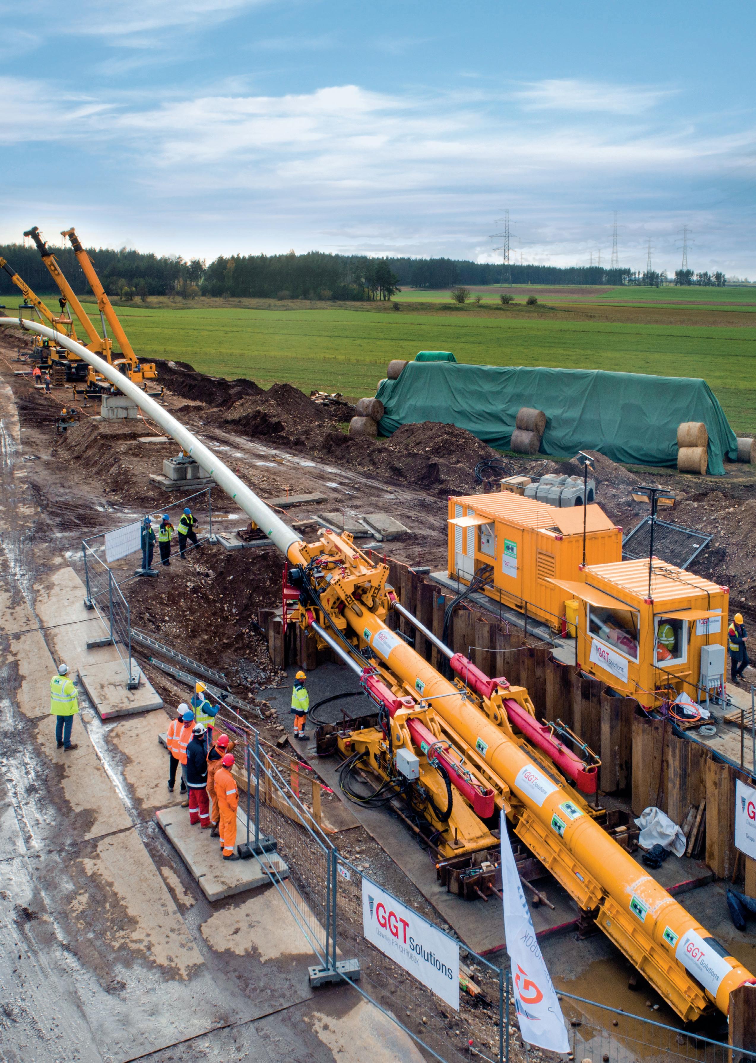
herrenknecht.com/directpipe


DIRECT PIPE ®
GGT Solutions S.A.
Gaz-System S.A.
Contractor:
Client:
READY-TO-USE (EPRS)


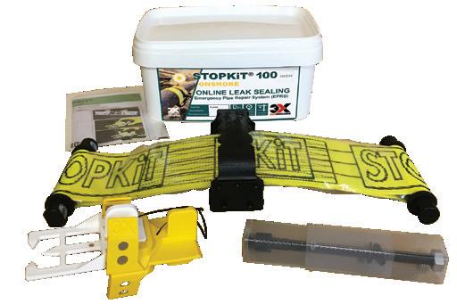
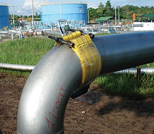
ONSHORE /OFFSHORE OIL & GAS
Roberta Pires, Flexible Pipe Systems Early Engagement Director, Baker Hughes, discusses features to be considered in a comparison between rigid and flexible pipes.
lexible pipes have been a revolutionary force in the oil and gas industry for more than 75 years, beginning in World War II when they were used to supply fuel to troops in northern France. The pipe used readily available materials arranged in a way that made it flexible and easy to install subsea at record speeds, mitigating the risk of bombing raids and casualties. Today, flexible pipes are used in offshore fields across the globe to transport oil, gas, water, and even dense CO 2. Despite their versatility, flexible pipes make up only 15% of the worldwide pipeline market share.
With diameters ranging from 2 - 22 in., the most commonly used internal diameter is 6 or 8 in. These pipes were initially designed for shallow waters, but have gradually been developed for use in deep and ultradeep waters, with the deepest on record being 3000 m in the Gulf of Mexico. In the coming years, there is significant demand for flexible risers and flowlines at 2900 m. Today, design pressure capacities reach as high as 750 bar (10 in.)
and 900 bar (8 in.) with design temperatures reaching as high as 170°C. The future looks bright for flexible pipes, and they continue to be a critical tool for the oil and gas industry.
Rigid or flexible pipes?

There are several reasons why both flexible and rigid pipes can be technical enablers, and consequently the only choice for a given application. A vast amount of infield pipes, however, could go either flexible or rigid, often triggering a passionate debate: Is there a significant cost difference? Which is installed the fastest? Which one is the most reliable? How does the type of field layout impact pipe type choice and should different types be considered? What is the most economic considering the complete service life?
Answering these questions is a task for talented concept and front end engineering design teams. However, certain variables come into play as well: lack of experience with either option, out of date information, or an incorrect
25
perception of the technical or commercial pros and cons could default to leaning to the familiar, rather than the best, option.
Development drivers
The most common indicators to drive field architecture and pipe selection are:
) Total cost of ownership (TOTEX), which groups capital expenditures of the subsea umbilicals risers and flowlines (SURF), the subsea production systems (SPS) and the costs related to pipes transportation, installation and vessel mobilisation.
) Net present value (NPV), setting to present value the revenue and operational expenses forecast combined with the TOTEX.
) Faster access to first oil, due to shorter supply time, increased vessel availability and faster installation speeds.
) Early on the level of return on investment (ROI).
) Breakeven oil price.
) Lowest CO 2 emission; a factor becoming increasingly important for decision-making.
) Pipeline re-use or re-purpose and field decommissioning.
Comparing TOTEX, as opposed to pipe price per meter is critical when comparing rigid and flexible pipe scenarios. Let’s break down the cost layers.
Flexibles cost per metre is often more expensive than rigid when it is solely carbon steel, without internal coating. When rigid pipe must be clad or full CRA, the cost of flexibles becomes cheaper per metre. This is more evident now due to geopolitical instabilities, post-pandemic supply chains being severely impacted, and inflation hitting several commodities, including the alloy elements used for these materials.
However, it‘s best not to compare rigid pipe price per metre directly with flexibles because the former is not the cost of a finished product, while the latter is. A rigid pipe is not a finished product until it is installed, and all 12 m rigid joints (or pre-welded bi, quad and even hexa-joints) are welded offshore using a J-Lay or S-Lay installation vessel. Moreover, often flexible pipe installation is cheaper than that of rigid pipes since it takes fewer installation days and daily rates tend to be lower. Thus, installation cost must be accounted for.
For the reel lay method, rigid pipe is welded and almost fully prepared at onshore spoolbases in 1 - 2 km lengths. After preparing and welding the 12 m joints, performing non-destructive testing (NDT) and protecting welds, the now continuous 1 - 2 km long pipe (stalk) is spooled onto massive reels (inner dia. ~20 m, whereas flexibles are typically 4 - 7 m). After reeling a stalk, the next one is prepared and the two are welded together until the full length is on the reel and
PLET XT RF XT RF PLET XT Offshore facility Rigid riser Rigid flowline Full rigid Rigid jumper Offshore facility Flexible riser Flexible flowline Full flexible VCM VCM VCM Offshore facility Rigid riser Flexible flowline Rigid riser + flexible flowline
26 World Pipelines / APRIL 2023
Figure 1. Elimination of rigid jumper and PLET with flexible flowlines. More compact horizontal distances with flexible risers.
Expect A Higher Standard

the product is at a finished state. For reel lay, it’s important to correctly account for installation cost as duration and daily rates can be different. It may also be necessary to add the cost of trips to the spoolbase to re-load, depending on pipe volume, pipe weight and reel capacity when using the reel lay method. Whereas re-loading of reels of flexible pipe onto the installation vessel may, if needed, occur in sheltered waters near the field location, with the help of a supporting lift-vessel. All of these durations and costs must be factored in.
A reduced installation campaign has benefits on overall execution certainty and allows the installer to take advantage of shorter weather windows. Faster installation and fewer vessels means less fuel consumption and lower CO2 emissions; flexible installation vessels CO2 emissions are, on average, 30 - 60 % lower.
The amount of associated subsea hardware may also differ. Flexible flowlines can be directly connected without pipe line end terminations (PLET) and rigid jumpers. If there is extra length when approaching the subsea hub, it can simply be laid on the seabed, creating a side curve. Some of the subsea structures will contain sensors, controls, and valves and are not there only to allow a precise subsea installation but to manage production and the life of the pipe. The SPS equipment eliminated, therefore, must be assessed for each field carefully.
When exposed to temperature and pressure cycles, flexible flowlines expansion and contraction are mild thanks to flexible pipe natural construction, eliminating the need for sliding structures to absorb axial movement. They do not require mitigation against free spans or vortex induced vibrations (VIV), and no need for buckle initiation sleepers as flexibles are made to bend and buckle, within limits. Generally, the amount of engineering for flowlines is much smaller for flexibles.
Flexibles may also eliminate rigid jumpers. This means eliminating long baseline metrology (LBL), jumper drawing elaboration, jumper cutting, welding, weld NDT, jumper factory acceptance testing, jumper subsea integration testing, and jumper rigging and transportation to quayside using mobile cranes. This process takes 14 - 35 days per jumper, depending on remoteness and teams’ efficiency.
The number of rigid jumpers depends on field layout and can vary significantly. For instance, it is common to have 10, 20 or even 35 jumpers. The elimination of jumper quantity and all associated design, transport, manufacture, test, and installation removes risk while creating an optimised installation schedule. There are some jumpers that will never be eliminated, like the ones that connect Xmas trees to manifolds or to a gathering flowline. If these are selected to be flexible, they will come as a finished product ready to be rigged, installed, subsea connected, and system tested; a process that will take one to two days per jumper.
Comparatively, rigid jumpers can be up to 45 m long, whereas flexibles can have any length and are adaptable to seabed bathymetry – providing flexibility for manifold and wells’ location late changes if needed.
Flexibles inner carcass material makeup is qualified to resist corrosion throughout its entire service life (316L, duplex, super duplex or super-austenitic stainless steels, or even nickel alloy carcass may be employed, depending on fluids corrosivity)
so regular inspection through pigging is not required. This is relevant when topsides space is scarce or non-existent.
Taking into account all the light construction vessels that can be easily adapted with rented laying equipment, there are twice as many installation vessels for flexible than for rigid. This may minimise risk of delays or enable cheaper and earlier installations.
Flexible components are highly standardised, which allows an optimised supply chain, often leading to shorter engineering and supply times. One of the most common critical path items for rigid pipes is the equipment that smooths riser top bending at connection to its offshore facility (flexjoints or tappered stress joints). For rigid, it typically takes two years to supply during regular demand periods, while flexibles equivalent takes 12 months.
Different types of field layouts and their financial impact
The main types of field architectures are satellite, manifold, loop and a combination of all three. While we review the technical differences between them, a key driver for the field layout definition is flow assurance, which ultimately aims to maximise the field production.
Satellite type, the most common field layout type offshore Brazil, is characterised by each Xmas tree being individually connected to the platform. Oil flows up directly, without being grouped with that from other wells. Satellite pipes ID are typically 8 or 6 in., diameters known today to have produced 45 000 boe/d and 6 000 000 gas m3/d (at 620 bar), respectively. Each well is typically serviced by a service and/or gas lift pipe. Umbilicals can be individually connected from the platform or from a system distributing unit, that is linked to the platform through a dynamic umbilical and allows control of up to five wells each.
Manifold type is characterised by using a manifold to group the production of neighbouring wells and then flowing oil up using two flowlines and two risers per manifold. The wells are typically all directional and located close to the manifold in so-called drill centres. Depending on the quantity of wells and manifolds, these risers must accommodate oil coming from 2 - 20 wells needing larger diameters, typically 10 - 14 in. The flowlines and risers come in pairs for redundancy and to allow for intermittent cleaning with hot oil, diesel or chemicals circulation (in case a pipe experiences constriction due to wax or hydrates buildup, for example) using one pipe system to provide the cleaning fluid to the other. In such a situation or even in preventive regular pigging, all wells must be shut. Manifolding reduces the number of risers and flowlines compared to satellite. On the other hand, there is increased SPS (manifold and connectors) and bigger pipes. Manifolds can be long lead items and critical equipment, which increases installation and operational risk for the field.
Pipes are also grouped in the loop type production. The main flowline is set to pass reasonably close to the wells and to be fitted with tee connectors called ‘In Line Ts’, which connect to the well’s Xmas trees. The main flowline is typically 8, 10 or 12 in., and the well jumpers or flowlines typically 6 or 8 in. As the main flowline and associated riser need to be cleanable, they are connected to an adjacent main flowline – another pipe
28 World Pipelines / APRIL 2023
grouping production for other wells. The two are connected with a flowline, all forming a loop. When there is a need to clean or pig one of the pipes all wells must be shut. The number of risers and flowlines is smaller than in satellite and potentially bigger than in manifold, depending on oil production volume from each well and field layout. The SPS hardware here is light and small, and most importantly, installed in line with the pipe in a continuous operation, saving time and mitigating risk.
One of the fundamental differences between those options is the profit lost due to production interruption for cleaning and well tax metering. The lost revenue can be estimated and should, whenever possible, be factored into the NPV as numbers can be significant.
Pipe ID is another fundamental difference. The greater the ID, the greater:
) The pipe cost, with a variance in a non-linear way and that differs between flexibles and rigid.
) The likelihood a higher capacity installation vessel is required. What the satellite option allows is ID minimisation; it is usually possible to remain below 8 in., which is cost beneficial, especially for flexibles and particularly in deep waters.
Expenditures with SURF and SURF installation account for 50 - 90% of SURF and SPS total expenditures, so is a key piece to optimise. Assessing different field layout arrangements, each
with its internal diameter and covering the two types of pipes, all while maintaining total production per day, is what may unlock optimisation.
Technical enabling
Pipes with ID greater than 22 in. must be rigid as no flexible supplier can produce larger flexibles. There are combinations of pipe ID and design pressure, or pipe ID and water depth, where rigid has a track record and flexibles don’t. Flexible qualification and track record varies for each supplier, and manufacturers should be consulted for their qualification limits. Fluid corrosiveness may also lead to rigid selection. This has been the case in the past five years for part of the Brazilian pipes that transport the world’s highest levels of CO2: part of the infield pipes are clad or mechanically lined rigid pipes. Stringent thermal requirements may require rigid pipe in pipe with passive insulation inbetween or actively heated pipes, of which there are qualified suppliers for both flexible and rigid options.
A classic case of enablement through flexible pipes is the North Sea. All oil produced with floating host facilities passes through a flexible pipe as it is hard to design a working rigid pipe configuration in its shallow water depths (average 90 m, deepest 700 m). A floating facility’s offset and movements are transmitted down along pipe leading to small bending radii at touch-down on the seabed, resulting in compression and fatigue that can be too strict for rigid but suitable for flexibles. Other technical benefits for flexibles are as follows.
Rough seabed topography and straighter flowline routings
• Flexibles accommodate to the seabed passing through free spans with no mitigation equipment, allowing optimised routes.
• Flexibles allow for sudden route turns at much smaller radius (for example ~3 m for an 8 in. pipe).
Reusability
• Reconnecting an existing flexible to a new well that produces more oil is an efficient way to revamp an asset’s production and is regularly done offshore Brazil.
• Flexibles offer versatility for field life extension, for example, a dynamic flexible can be re-purposed to be static and the fatigued top section of flexible risers can be replaced or just re-terminated.
Congested fields
• Flexibles touch down zone horizontal distance is smaller, making efficient use of limited space.
• During installation, flexibles don’t require an installation pile to be initiated, thus reducing risks of initiation wire touching already installed subsea structures. Also, it is simpler to solve crossings non-destructively.
Reliability
• Despite the general perception, flexible and rigid pipes failure rate are of the same order of magnitude.
• This is the conclusion reached by a joint industry programme that included key industry stakeholders.
• The most frequent flexible incident is seawater ingress into the annulus, an event that does not usually lead to pipe failure as long as it is accounted for in design.
Integrity and monitoring (I&M):
Today, the I&M portfolio includes tools that allow understanding:
• Is annulus flooded?
• Are tensile wires intact?
• What is annulus fluid composition along time?
• Is it safe to extend pipe service life?
• A pipe health dashboard can be accessible on your smart phone.
Conclusion
From World War II to the present day, the inventiveness and passion of thousands of people have brought flexibles to constantly push past technology limitations, enabling deeper, hotter and higher-pressure field development, and bringing execution certainty to oil and gas developments. The need to transition towards greener technology and resources is a new challenge in product and business development; one to ignite the passion for innovation guided by the vision of safe, secure and affordable energy to all corners of the world.
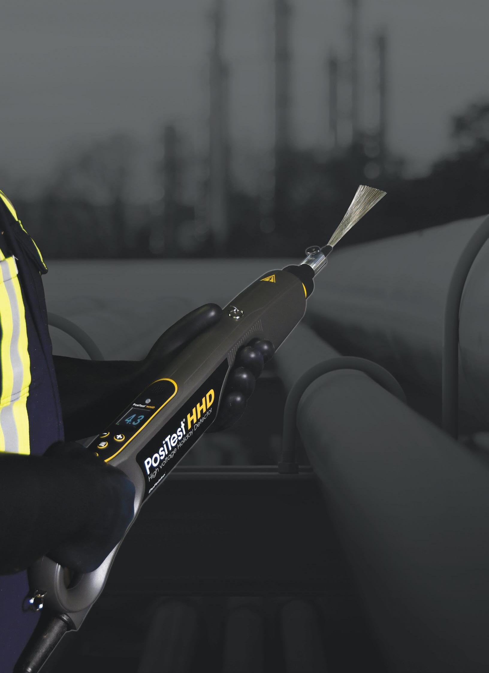
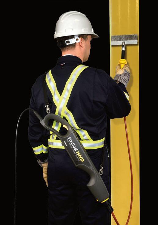
Detects pinholes and holidays using pulse DC High voltage Holiday Detector
n Lightweight, ergonomic design provides comfortable all-day use, reducing operator fatigue
n Regulated pulse DC voltage output that won't change under load ±5% voltage accuracy
n Voltage calculator feature choose one of 11 international standards, and input the coating thickness to automatically calculate the required test voltage
n Long Form Certificate of Calibration included with each instrument
DeFelsko Corporation l Ogdensburg, New York USA Tel: +1-315-393-4450 l Email: techsale@defelsko.com Choose from a wide range of rolling spring and
ava +1-315-393-4450 www.defelsko.com
Optional handheld wand accessor y converts the detector into a wand configuration ideal for testing hard-to-reach areas
wire brush electrod custom sizes
he Pipeline and Hazardous Materials Safety Administration (PHMSA) introduced a new rule in 2019 that required natural gas transmission operators to reconfirm maximum allowable operating pressures (MAOP) of certain pipelines located in Class 3 or 4 locations, high consequence areas (HCA), or moderate consequence areas (MCA). To address this requirement, PHMSA outlined six separate methods operators may pursue:
• 1. Pressure test.
• 2. Pressure reductions.
• 3. Engineering critical assessment (ECA).
• 4. Pipe replacement.
• 5. Pressure reductions for segments with small potential impact radius.
• 6. Alternative technology.
To minimise the impact on operations, pipeline operators may opt to conduct an ECA. This procedure can allow the avoidance of hydrostatic pressure tests and pressure reductions that interrupt product delivery. An ECA is essentially a fitness for service analysis of material properties, historical data, survey reports, and threat assessments. The result determines a predicted failure pressure thereby reconfirming or re-establishing the pipeline’s MAOP. A key component of an ECA is determining the defects remaining in the pipe which can be efficiently performed with inline inspection (ILI). Potential threats such as geometric anomalies, metal loss, and crack-like defects can be detected utilising various technologies deployed
via ILI tools propelled by product flow with minimal interruption to pipeline operations.

Louisville Gas and Electric (LG&E) owns and operates a vast network of natural gas pipelines throughout the greater Louisville, Kentucky (USA). Many of these pipelines are operating at pressures less than 250 psi and consist of varying diameters. In addition, a considerable number of these pipelines were built in the 1950’s utilising construction standards that have since become outdated. From the perspective of ILI, these pipelines are considered challenging due to the combination of operating pressures and pipeline geometry. Three of these pipelines are requiring MAOP reconfirmations and LG&E has opted to pursue ECA’s to satisfy PHMSA requirements and avoid the costly shutdowns associated with hydrostatic pressure tests or operating pressure reductions. To facilitate the ECA’s, numerous ILI technologies are required; the suitable inspection methods include calliper-based, inertial measurement (IMU), magnetic flux leakage (MFL), and electromagnetic acoustic transducer (EMAT) technologies.
Historically, LG&E has worked with ROSEN’s ILI solutions extensively for integrity management purposes in pursuit of safe and efficient system operation, as well as compliance with associated regulatory demands. The relationship would continue with this effort in determining the appropriate ILI solutions.
The first step is to examine the pipelines in detail. LG&E wishes to inspect three 16 x 20 in. multi-diameter natural gas pipelines operating at pressures less than 250 psi. These pipelines include 1.5 dia. 90° bends with a considerable number involving spacing less than 3 ft. Restrictive fittings
31
Lance Wethey, Technical Solutions Specialist, ROSEN, USA, explores facilitating engineering critical assessments of challenging pipelines with ILI.
such as these occurring in a low-pressure gaseous environment challenge data capture due to the expected ILI tool run behaviour. This is a consequence of the compressibility of the natural gas. ILI tools will often slow or stop during traversal of tight bends and diameter reductions as the differential pressure (ΔP) required to maintain momentum increases. The delay in achieving the increased ΔP requirement typical of low-pressure gas pipelines allows the downstream pressure to decrease, often resulting in a velocity excursion once the ILI tool resumes travel. Data capture quality is reduced during these high velocities and there is a heightened risk of ILI tool damage. ILI solutions deployed in these systems should ideally possess optimal sealing ability while simultaneously effecting minimal friction against the inner pipe wall. An optimised ILI tool achieving both parameters will narrow the ΔP requirements when traversing straight pipe sections and restrictive fittings, thereby stabilising run behaviour and allowing acceptable data capture.
ROSEN readily offered solutions satisfying high resolution deformation, geometry, mapping, and metal loss inspection requirements compatible with these challenging pipelines. In fact, LG&E had already included ROSEN’s 14 x 20 in. GEO and MFL-A ILI tools in their integrity management programme. Although, prior to this endeavour no such ILI options existed industry-wide capable of identifying axially oriented flaws and crack features in multi-diameter low-pressure gas pipelines. MFL-C and EMAT inspection technologies are ideally suited to identify these sorts of anomalies, but existing ILI tools that include these technologies were primarily developed for single-diameter high-pressure transmission pipelines. To properly facilitate the ECA, LG&E worked with ROSEN in developing new multi-diameter MFL-C and EMAT solutions compatible with the challenging conditions presented by these three pipelines.
Defining the solution
Developing new inspection solutions occurs across several distinct phases. The first step with any ILI tool development involves defining the desired capabilities. The ROSEN engineering team must have a clearly defined target to base any proposed design. Essentially, all static and dynamic parameters must be understood. Geometry details and
expected operating conditions specific to the pipelines need to be catalogued to dictate a range of operability.
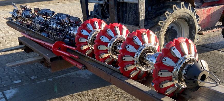
Extensive review of all pipeline geometry information is conducted to determine the mechanical limitations. Ideally, this information is made available via pipeline feature lists and pipe tallies derived from previous ILIs. When available, this source offers the most accurate and current overview of a pipeline’s geometry. While construction records can be used, this carries a heightened risk for older pipeline systems as documentation may not be complete and can be lost over time as owners and operator personnel change. In this scenario, ROSEN had previously inspected these three pipelines – therefore details pertaining to number and type of fittings, diameter transitions, wall thicknesses, and distances were readily available. Additionally, LG&E provided details of any pipeline modifications that have since occurred. Compiling all known details of the three pipelines permitted designation of the most challenging geometric aspects. The proposed ILI solutions must not only be capable of navigating these pipelines, but also capture complete data during traversal.
In addition to reviewing the pipelines’ geometry attributes, the anticipated operating conditions must be considered. The expected product pressure and flowrates will determine the available ΔP to propel the ILI tools. Precise values can be difficult to predict due to the transient operating conditions of natural gas transmission pipelines that feed distribution systems. For example, variances in weather can influence product demand and alter the available line pressures with minimal notice. To prepare for this, a relatively low available ΔP must be targeted to minimise impact on pipeline operation. It must be noted that whatever value for ΔP is designated, there can be other unknowns such as debris, pipe wall condition, and girth weld quality than can impede ILI tool traversal, thus significantly increasing the forces required for traversal. Essentially, ΔP requirements for ILI are not a tool specific parameter, but a combination of tool and pipeline characteristics. Regardless of ILI tool design, higher than anticipated ΔP requirements may occur during the actual inspections.
After considering all the known details of the pipelines to be inspected, a design criterion was established that the ROSEN engineering team referenced to determine the tooldesign and testing programme. In summary, the proposed ILI tools were designed by targeting minimum requirements that considered both pipeline geometry and potential operating conditions. The governing guideline was to design ILI tools that can achieve full circumferential sensor coverage while maintaining propellant sealing with minimal friction in 16 - 20 in. pipeline diameters. Essentially, the tools must be capable of collapse and expansion with minimal surface contact with the pipe wall.
Designing the solution
The initial step in tool design began with the measurement systems. Utilising
32 World Pipelines / APRIL 2023
Figure 1. 16 x 20 in. MFL-C tool.
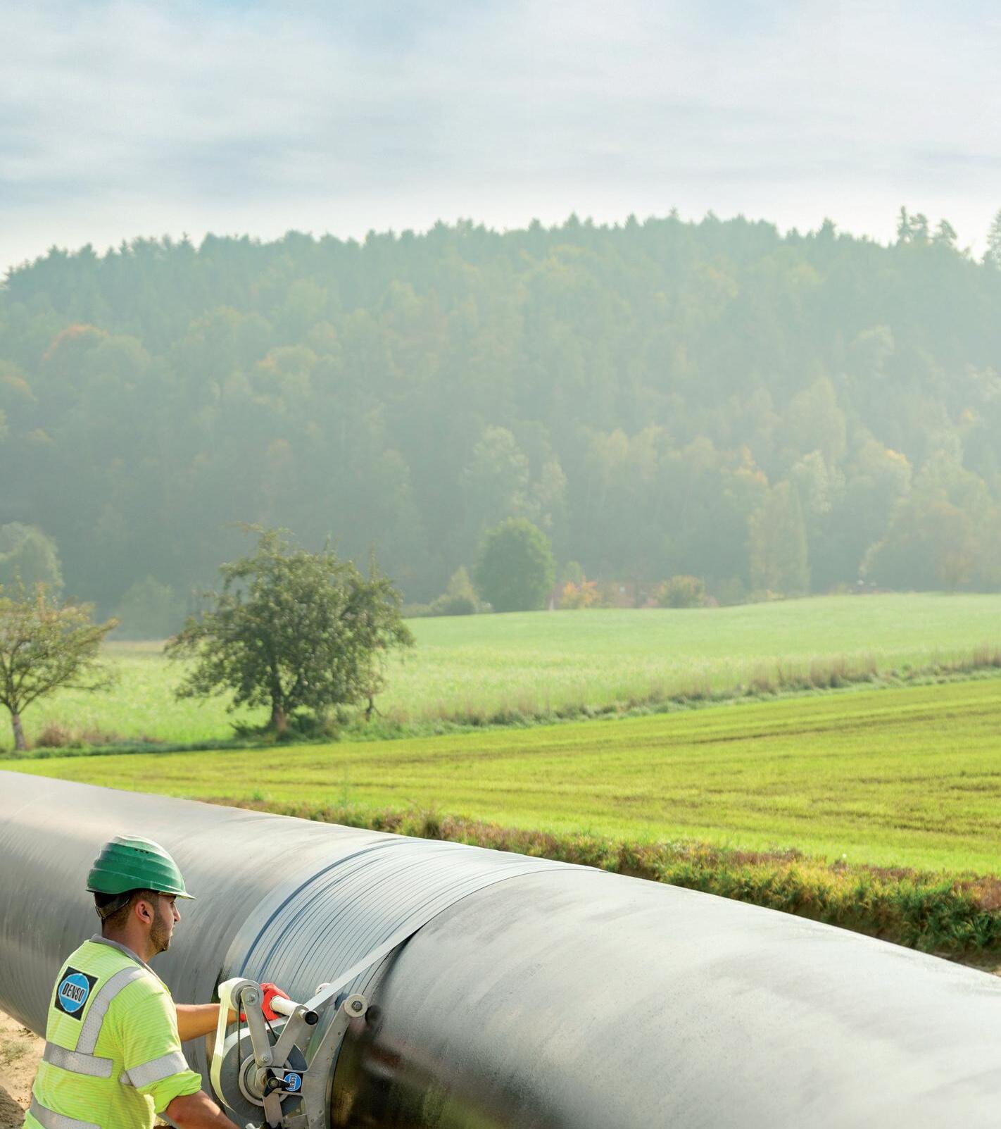
100 Years DENSO. Advanced in Sealing. Lifelong Safety is Everything. 100 years of innovation power. For safeguarding your pipeline. For protecting people and nature. denso-group.com
existing ROSEN sensor technologies and electronics systems, the ROSEN engineering team drafted the components that would implement the measurement technique to pipe wall. Both MFL-C and EMAT inspection technologies require magnetisation of the material being assessed; these components are referred to as magnet yokes. The magnet yokes generate magnetic fields in pipe material and suspend the sensors that capture the measurement signal. The yokes’ dimensions must consider numerous parameters to permit mechanical passage, sensor coverage in multiple diameters, as well as sufficient pipe wall magnetisation.
To reduce friction, the yokes incorporated wheeled elements in the magnet brushes. Magnet brushes are the component that directs the magnetic field to the pipe wall. Utilising wheels offers the benefit of minimal surface contact with pipe wall as well as the functionality of the wheels themselves. Consequently, the application of the magnetic field is impeded by the gap between the magnet brushes and the pipe wall. This simply limits the magnetic saturation WT range of any single magnet configuration. The yokes were designed to accommodate magnets of varying strength, thereby allowing multiple configurations to suit the preferred application.
The magnet yoke suspension system itself is one of the more innovative aspects of these measurement segments. It must be capable of smooth collapse and expansion between the 16 - 20 in. diameters while remaining both robust and compact. Additional efforts are pursued to mitigate the impact of debris on the suspension system functionality.
The sensor coverage extent of individual measuring segments will then determine the actual number of segments necessary to achieve complete circumferential coverage of all pipe diameters to be inspected. In this circumstance, the MFL-C will require four measuring segments and the EMAT, three. The differing number of measuring segments between the tools was a consequence of the required widths of individual yokes. The magnetic field applied by the EMAT measurement system could be induced axially, requiring narrower yokes than the MFL-C, which induces a circumferentially oriented magnetic field. A narrower yoke allows more sensor planes per segment, thus requiring fewer segments to achieve full pipe wall coverage.
The final component of the measurement system includes the odometer system that records distance as well
as triggers the sensor capture based on the designated sample distance. This method of sensor triggering is referred to as ‘distance mode’. The sensor capture may alternatively be configured to operate in ‘time mode’ that sets the triggering to a designated time interval when there are debris concerns that may cause odometer slippage. This mode increases the power draw and total data storage consumption as a result. There are three separate odometers to ensure the system maintains functionality whenever individual odometers cease spinning during traversal of fittings, for example. The odometer system is mounted on a rear segment that also contains a transmitter for tracking purposes, as well additional electronic system components.
Upon completion of the measuring system designs, focus was then turned towards the pull unit systems that will tow the measurement segments by effecting a seal to capture the force applied by the propellant medium. The same basic principles in designing the measuring segments are still relevant here – maintaining functionality in all diameters with a minimal amount of friction.
ROSEN had already developed numerous multi-diameter ILI solutions and the experience gained from these previous efforts will manifest itself in this application. Successful designs will simply be scaled to accommodate the specific diameters.
The pull unit design involves a canvas membrane attached to flexible support arms. The membrane captures the product flow while the support arms expand and collapse to conform to the pipeline inner diameter. Polyurethane (PU) components adorn the outer perimeter and contact the pipe wall to maintain the seal that minimises product bypass. The resultant sealing plane collapses and expands much like an umbrella. The support arms are reinforced with a spring assembly that applies an outward force that centralises the assembly. Wheeled elements are installed at the outer edge of the support arms to reduce the amount of friction applied to the pipe wall.
Since tool bodies fall out of centreline when traversing tight bends, the sealing plane may lose effectiveness. Therefore, it is essential to incorporate numerous sealing plane segments to ensure continued towing force through bends and other pipeline features. A minimum of four sealing planes is considered adequate to ensure any momentary loss of seal is compensated.
Additionally, the central bodies of the sealing plane segments also contain the batteries that supply the power to the measurement system. The tools are configured to allow for additional sealing plane segments to increase operating times for inspections with longer durations.
Throughout the design phase, LG&E was provided with incremental updates to allow expression of any concerns. Once LG&E and ROSEN were both satisfied with a final design, the manufacturing of components and assembly could then proceed.
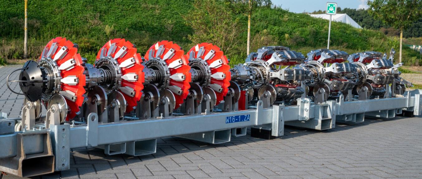
34 World Pipelines / APRIL 2023
Figure 2. 16 x 20 in. EMAT tool.
We are running out of space...
Our inventory in sales & rental in pipeline equipment is out of this world. We have a huge amount of machines from all the big brands that are ready for worldwide delivery, or even further if you want...
You can build on BAUMA!

und Handels GmbH
BAUMA-PIPELINE.COM Vermiet-
Testing the solution
Once the newly developed 16 x 20 in. MFL-C and EMAT ILI tools were fully assembled, the testing phase commenced to verify functionality and to determine if the tools can achieve mechanical performance criterion established prior to design. Observations during this stage will determine if the ILI tools are fit for service in a live pipeline. Specifically, consensus must be achieved that the expected tool performance can overcome the operational and geometric challenges that pose the greatest risk to quality data capture.
Just as with all ILI tool developments, pull test validation must occur to ensure that the measurement systems can accurately meet inspection specifications. This involves pulling the tools via a winch system through various pipe segments that contain artificial anomalies/defects. After several pulls at varying speeds, captured data is downloaded from the tools and sent to the evaluation department. This effort verifies that the tools’ measurement capabilities are meeting the specifications regarding probability of detection (POD), probability of identification (POI), and sizing accuracy.
The most extensive segment of the testing phase is the pump testing. A test loop is assembled that incorporates features that are representative of pipeline geometry that the tools are expected to encounter during the actual inspections. This includes various bends and combinations thereof in both 16 in. and 20 in. dia. The tools are propelled through the test loop multiple times in both directions at various speeds. The test loop is outfitted with pressure sensors that allow the ΔP values to be recorded as the tools traverse the various features. The
primary purpose of the pump test is to validate the mechanical functionality of the tool from three essential aspects – the amount of force (ΔP) required to traverse restrictive features, the maintaining of adequate propellant sealing, and the consistency of data capture behaviour. Tool performance through the test loop should be repeatable without any significant outlier before deeming a tool is fit for service.
The test phase concluded only when both LG&E and ROSEN were confident the tools were fit for deployment. The tools’ performance during testing satisfied the targeted specifications, yet the actual inspections will determine if the design is considered final or if any iterative improvements are needed.
Conclusion and outlook
ROSEN and LG&E successfully collaborated to inspect two of the three targeted pipelines thus far, and the third remains on schedule for inspection in 2023. As a result, the ECA’s may proceed without service interruption.
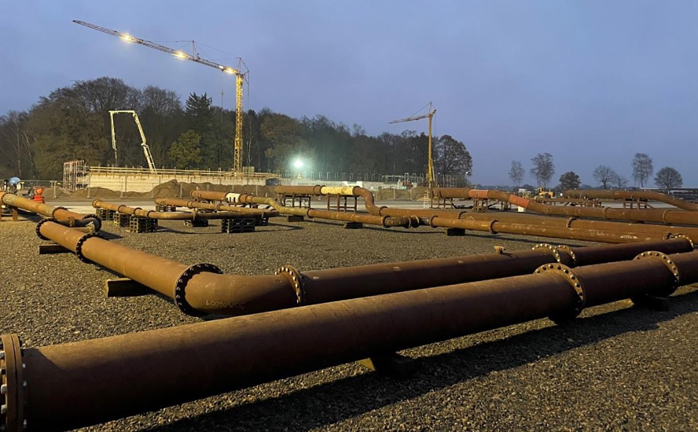
The development of multi-diameter MFL-C and EMAT inspection tools represents a milestone in industry capabilities, especially considering the optimisation for operation within challenging low-pressure gas pipelines. The feat was only possible through the collaboration of LG&E and ROSEN. Member involvement was critical for a successful development where everyone brought their own expertise and perspectives.
Pioneering efforts such as these are necessary to improve integrity management and maintain safe and efficient energy delivery. Facilitating ECA’s of challenging pipelines expands the options available to operators in pursuit of these goals.
36 World Pipelines / APRIL 2023
Figure 3. The test loop.
Hifi provides turnkey distributed fiber optic sensing systems specifically engineered for monitoring of pipeline assets.
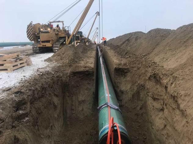


Whether you’re managing a new build or retrofit project for leak detection, ground disturbance, slope stability, pig tracking, or distributed flow assurance, Hifi delivers the world’s most advanced pipeline monitoring platform from sensor deployment through to control room interface software.
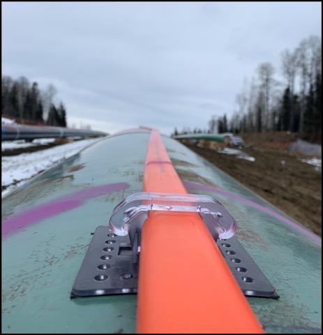
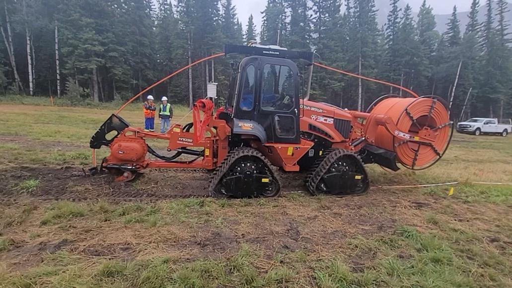
Contact us today Hifieng.com info@hifieng.com (403) 264-8930 | (346) 201-5025
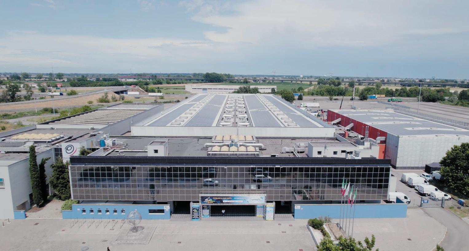


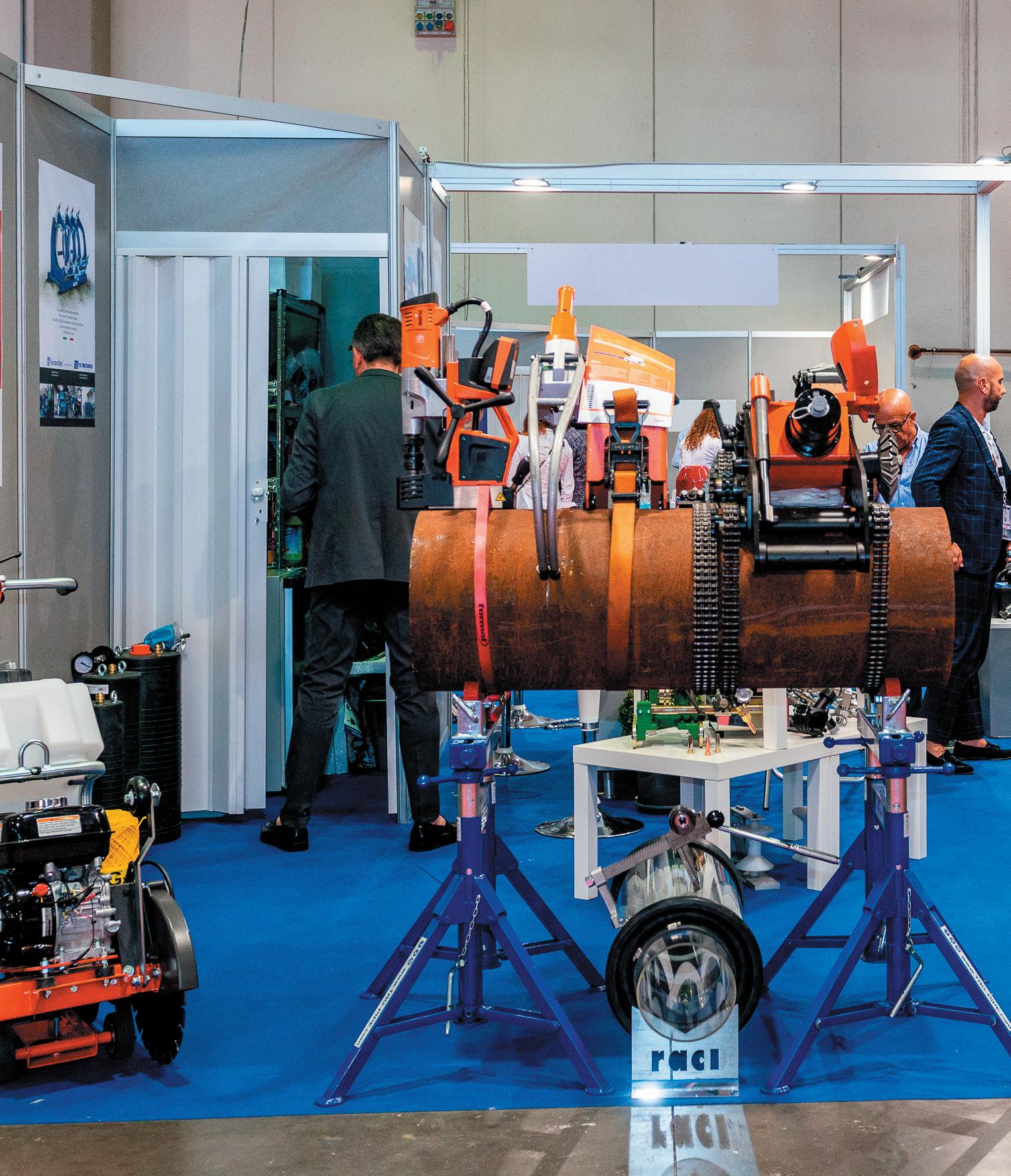
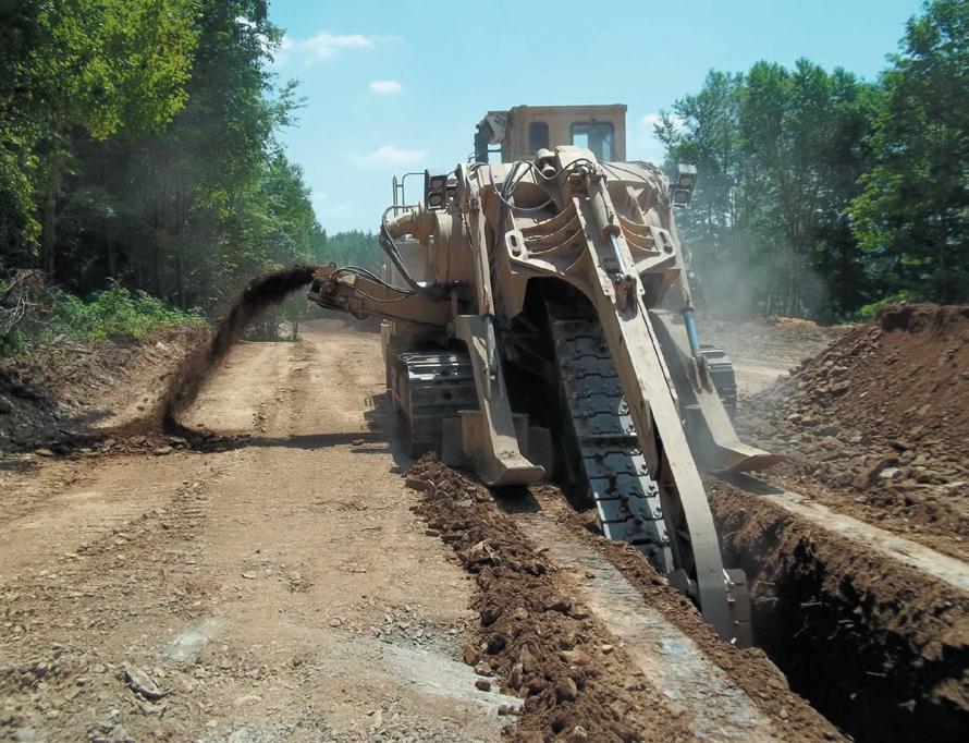
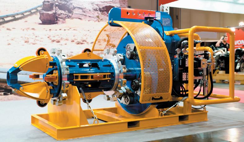
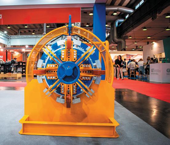
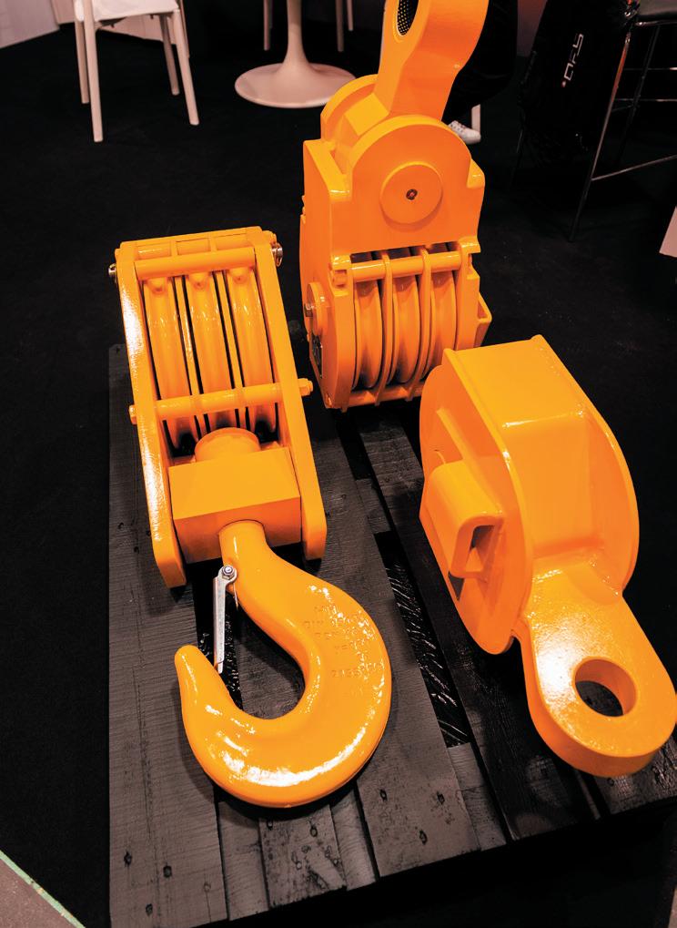

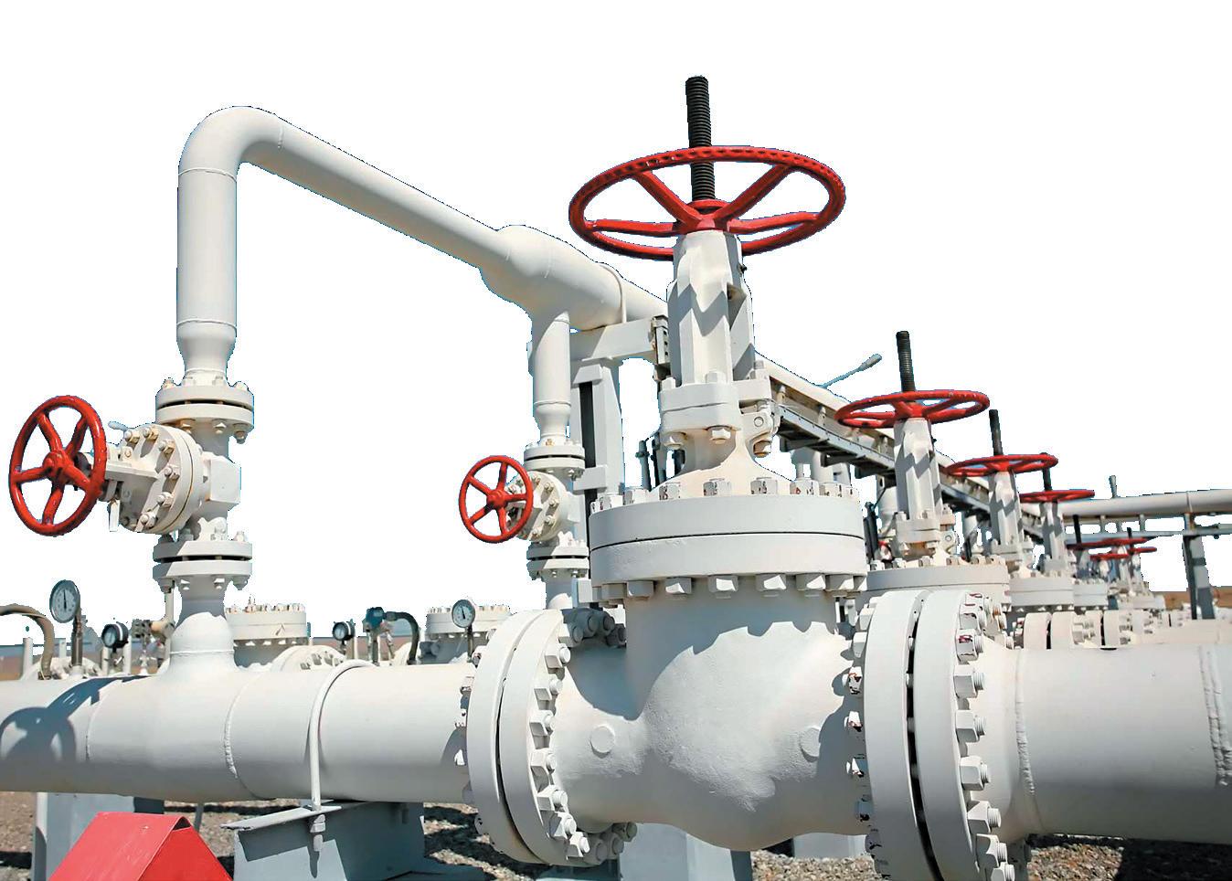
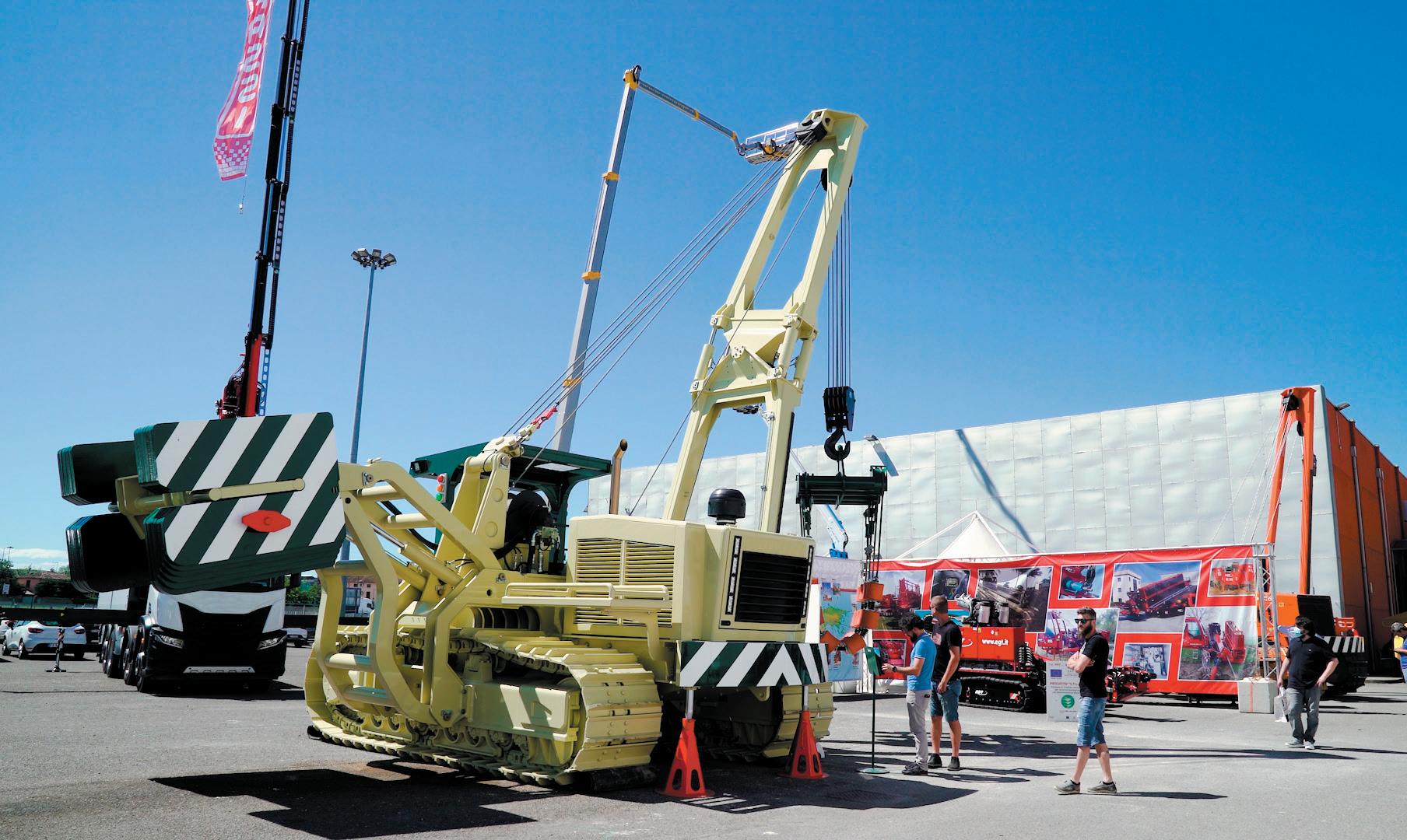
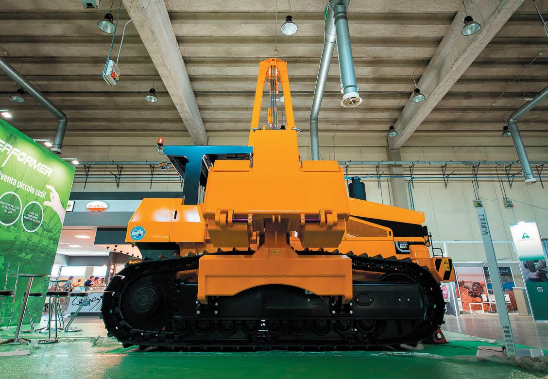
THE UTILITY CONSTRUCTION Pipeline & Gas Expo 29-31 May 2024 THE ONLY EUROPEAN EXHIBITION FULLY DEDICATED TO THE MID-STREAM SECTOR AND THE GAS, OIL & WATER DISTRIBUTION NETWORKS 3rd Edition FOR INFO AND STAND BOOKINGS: info@pgexpo.eu www.pgexpo.eu Ph. +39 010 5704948 SOCIAL MEDIA 200/2022 PLNG22E Fiera certificata An exhibition audited by
he world’s awareness of the vital need for oil and gas increased significantly as a result of the war in Ukraine. Perhaps more than at any other time, we all learned the criticality of moving essential fuel supplies from location to location and the crucial role of pipelines in that transportation.
Even had the war not happened, the global energy transition alone would have spiked our understanding of the need for pipelines. As more renewable energy comes online, oil and gas still remain essential components of the daily lives of every individual and effectively every industry worldwide. Moving through a network of pipelines, that in the US and UK already span almost half a million kilometres, the growing strains on current energy transportation around the world have prompted many countries to plan expansions of their pipeline networks.
Pipelines are one of the safest and most cost-effective methods for transportation of petroleum, natural gas, biofuels and hazardous liquid products. Building new ones is not an easy prospect, as we saw when the current US administration cancelled the Keystone Pipeline on its
first day in office. That intensifies the imperative that we conscientiously and proactively maintain those pipelines already in place; just as roads and bridges require evaluation and maintenance, pipelines are at risk of deterioration over time. The increasing global demands on energy transport systems due to population and economic growth highlight the need to invest in the analysis and maintenance of ageing pipeline infrastructure. Even though they don’t get the attention they deserve, ageing pipelines are at risk of potentially harmful failure every bit as much as ageing road and bridge infrastructure, if not more.
The importance of routine pipeline inspection

Pipeline inspection requires assessing the infrastructure for damage, defects or signs of corrosion. The necessity of regular pipeline maintenance and assessment can significantly reduce the potential for leakage and the economic and environmental disruption that inevitably follows.
Since the first petroleum pipelines were installed in the late 19th century, ongoing maintenance and manufacturing practices have improved
39
NDT techniques in pipeline inspection address potential risks before immense damage can occur, says Danny Keck, President, American Society for Nondestructive Testing (ASNT) and Independent Inspection, USA.
the quality and integrity of pipeline infrastructure. But the pressure is increasing. In the US, The Infrastructure Investment and Jobs Act of 2021 includes a new safety and security programme to replace corroded and leak-prone, high-risk natural gas pipelines that, in some cases, are over a century old.1 The new legislation represents a step in the right direction to improving safety in the energy transportation system.
How can we meet the growing demand for assessment without shutting pipelines down for examination? The technology is readily at hand.
With non-destructive testing (NDT), pipeline evaluation can happen accurately, affordably and immediately. NDT is an evaluation process using various technologies and techniques to inspect a structure without injuring or destroying its serviceability. NDT is currently used in the oil and gas pipeline industry to assess the occurrence of both internal and external pipeline damage. What the industry must now emphasise is the need that NDT inspectors have the upgraded training and certification needed to ensure they can apply the latest technologies.
The need to conduct NDT assessment throughout the lifecycle of a pipeline, from the initial manufacturing and construction to its continuous operation, is key to costefficiency and human safety. NDT can significantly optimise a pipeline’s life expectancy while protecting the level of material integrity throughout its lifespan. One technological advancement illustrates the need for enhanced training and certification.
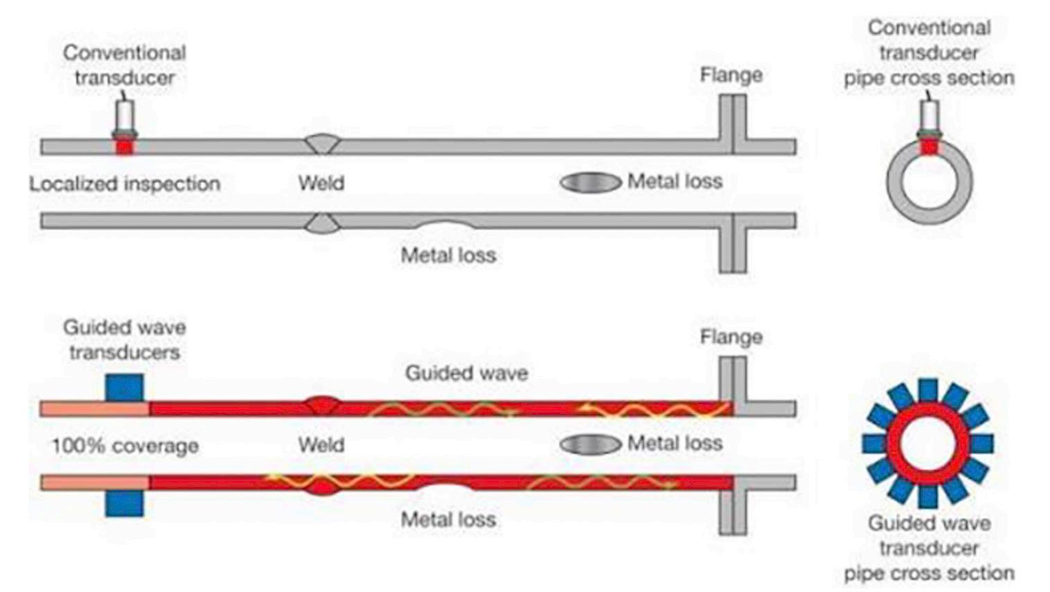
The NDT process most often applied in oil and gas pipeline inspection is ultrasonic testing (UT), which uses ultra-highfrequency sound to render an image with different acoustic density and velocity. More recently, industry professionals have adopted guided wave testing (GWT) methodology, in which the controlled application of ultrasonic waves travel along an elongated pipeline structure to detect potential material loss or corrosion. Whereas the UT method is only able to analyse the small, isolated area where the sound transducer is placed, the GWT method can inspect a much larger area of the pipeline. GWT utilises the pipe wall thickness as its wave guide and dispels ultrasonic frequencies through the length of the pipeline. Inspection experts in the oil and gas industry
increasingly favour the GWT method over the UT method as it saves precious time and cost during assessment.
The regular application of innovative NDT techniques such as GWT, make it possible for owners and operators to identify and prevent further corrosion and more expensive repairs in the future. As the GWT method becomes more widely accepted as industry standard and new inspection tools such as GWT permanent monitoring devices enter the field, the oil and gas industry must adopt more thorough training programmes and certification requirements for NDT professionals to keep their skills up to date with such new technology.
NDT in today’s pipeline industry
For the past two decades, the standards for condition assessment of the majority of pipelines in the US have been managed by the federal government under the US Department of Transportation’s Pipeline and Hazardous Materials Safety Administration (PHMSA). PHMSA regulates and oversees pipeline safety and the transportation of hazardous materials in the US.2 It operates under the federal laws that secure transportation of energy and other hazardous materials by pipelines, and other modes of transport, to reduce the health and safety risks for the population and the environment.
In its enforcement of federal safety laws such as the Pipeline Safety Act of 2011 and the PIPES Act of 2020, PHMSA works to improve damage prevention and leak detection of pipeline utilities with public education resources, and conducts extensive research and investigation into reported incidents.
Pipeline inspection requirements as authorised by federal statutes and enforced by PHSMA vary by pipeline material and the product in transport. The regulation of detailed inspections ranges from every two years to every nine years, with the various timelines for different types of pipelines presented in a complicated manner within the Pipeline Safety Regulations.
Confusion over the frequency of thorough pipeline inspections can lead to a gap in obtaining data on a pipeline’s integrity. Even if a pipeline shows no sign of external damage, it’s important to conduct routine inspection to evaluate internal damage and threats of failure as part of your assessment management plan. As a recommended practice of inspection, NDT methods remain the most effective techniques of defect assessment in the industry for their feasibility and costefficiency.
State departments of transportation can take further steps to clarify confusing federal mandates and increase the requirements of regular inspection. For example, the California Code of Regulations requires pipeline operators to “inspect all active gas pipelines in sensitive areas that are 10 or more years old for leaks and other defects at least once a year.” 3
Throughout the decades, the transition of the oil and gas pipeline inspection industry from analogue to digital has encouraged drastic technological advancement and improved NDT inspection practices.
40 World Pipelines / APRIL 2023
Figure 1. The comparison of ultrasonic testing (UT) to guided wave testing (GWT) methodologies (Source: ASNT).
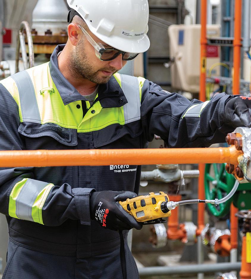

Using innovative, ever-evolving solutions and our expert knowledge, we provide the best services to support all of your operations. We have the in-house capabilities to combine the services you need: inspection services, pipeline management, environmental services, and industrial services. Contact our team for more details: info@intero-integrity.com intero-integrity.com Meet Us at PTC 2023! Booth #G12
A pig in a pipe
For pipelines with launchers and receivers installed during construction, NDT is virtually painless and allows inline inspections (ILI) to be accomplished easily and frequently. Originally designed to just clean the pipeline internally, pigs can also evaluate pipelines with various NDT methods to analyse corrosion depth and location, identify dents and severity, and sometimes cracking.
Smart pigs can be inserted into a pig launcher at a specific location in the pipe that has the capability in its layout of tube turns and valves to allow the tool to successfully run through the line. The ILI tool can then travel through the main line of the pipeline, collecting crucial data until it can be removed at a downstream receiver location. Different instruments, from magnetic flux leakage tools to ultrasonic tools, can be used to assess different types of pipelines and detect different types of defects.
Although pigs can improve cost-effectiveness and prevent costly efforts to dig up pipeline or conduct underwater diving, the capability is not always present in pipelines. For pipelines built before the 1960s, the decade when manufacturers began constructing oil and gas pipelines with ILI capabilities in mind, pigs are not a viable option for routine inspection. Thus, the need for enhanced skills training to apply the NDT technologies most appropriate to the situation.
The value of proper training
The inability to pig older pipelines requires more advanced inspection by properly trained and qualified NDT personnel. With different types of pipelines, from underground to aboveground to subsea, come different challenges and inspection techniques that require specialised skills. As inspection techniques and technologies continue to progress, it’s important that the training of inspectors and NDT professionals keeps pace with the adoption of new tools and methods.
The American Society for Nondestructive Testing, Inc. (ASNT) is the world’s largest technical society for NDT professionals. Its certification and standards programmes led by industry experts help promote the NDT profession and facilitate NDT research and technology applications.
ASNT’s Industry Sector Qualification – Oil & Gas (ISQ-O&G) programme is an advanced practical performance qualification examination available to inspection professionals for an affordable cost.4 The purpose of the ISQ programme is to offer trained and certified NDT personnel qualified to serve in the oil and gas industry. Led by expert personnel of the oil and gas industry, the programme qualifies NDT personnel through hands-on performance demonstration exams.
“The ISQ programme:
) Standardises performance demonstration initiative testing of NDT technicians.
) Alleviates the burden of owner/operators from providing their own NDT performance demonstration programme.
) Provides a programme for owner/operators that do not have their own NDT performance demonstration programme.
) Provides global availability.
) Establishes an industry recognised programme for the oil and gas sector while minimising the impact of cost and redundant testing of NDT technicians.”
ASNT certification is the most recognised credential for NDT, widely regarded as the standard certification for the industry. Although ASNT certification and training programmes are not the only ones available in the industry, they highlight the importance of inspection personnel undergoing regular training to ensure their technical skills remain up to date with the current tools and technology.
Better NDT training can better the damage detection of pipelines
The improvement of inspection procedures and training practices can significantly enhance time and cost-efficiency to protect the public safety of all individuals. Industry experts have learned that advanced technology needs advanced training.
For inspection personnel, obtaining certification to perform a specific NDT method is essential to conducting the most efficient and effective evaluation to yield the most accurate results. Inspectors who are specifically trained and certified to perform UT can advise better maintenance recommendations that will prevent disruption in people’s daily routine and avoid potential expensive pipeline replacement in the future.
While professional communities such as ASNT can offer in-depth training sessions and testing for general certifications, it’s the responsibility of the companies that introduce new technologies, as the experts of their own product, to ensure personnel are well-trained in using the new technically advanced tool.
Today, ASNT board members and oil and gas industry experts are committed to expanding the ISQ Oil & Gas training and certification programme and its resources for NDT professionals. However, more advocacy in the industry is needed. The oil and gas pipeline industry should further advocate expanding technique validation and increase training and performance demonstration examinations to enhance their inspections, reduce costs, and minimise the number of assessments needed.
The ageing infrastructure of the world’s oil and gas pipelines poses a threat to communities. NDT techniques in pipeline inspection can help detect potential leak risks and corroded material, and address them before immense damage can occur and negatively impact the health of people and the environment. It’s essential for all operators and inspectors within the oil and gas industry to push for more extensive training of personnel with the introduction of new tools and technology to ensure inspections can be properly conducted. With the expansion of NDT training and the evaluation of more pipeline per inspection, pipelines can remain one of the safest and most cost-effective methods of energy transportation with the neverending increasing demand on the system.
References
1. www.whitehouse.gov/briefing-room/statements-releases/2021/08/02/updated-factsheet-bipartisan-infrastructure-investment-and-jobs-act
2. phmsa.dot.gov/regulatory-compliance/phmsa-enforcement
3. www.conservation.ca.gov/calgem/for_operators/Documents/Pipelines-Facilities/ Requirements-for-Oil-and-Gas-Pipelines.pdf
4. asntcertification.org/Get%20Certified/ISQ.aspx
42 World Pipelines / APRIL 2023
y providing the power of clarity to enable the best outcomes, NDT Global continually strives to push boundaries and set new standards for inline inspection (ILI), data analysis, and integrity assessment. This sentiment could not be truer with our latest technology development, ETECTM, a technology platform that creates innovative solutions and opportunities to capture new datasets during the ILI inspection process.
Operators and regulators across the energy industry, striving for green energy alternatives, are re-purposing ageing pipelines that currently transport petroleum and natural gas to pipelines that will transport hydrogen or CO2 in the future.

By leveraging advanced technologies and measurement principles, like eddy current, pipeline operators are able to gain critical information to help understand and address any potential risks prior to injecting hydrogen into their pipelines. NDT Global’s ETEC technology provides insights such as material properties, as well as direct measurement of the stresses on the pipeline. This provides operators the ability to identify areas of crack susceptibility or the potential for any other injurious features.
Geohazards
The first application of ETEC technology, ETEC Geo, provides pipeline operators facing geohazard challenges with highly accurate data and actionable insights to address geotechnical threats.
Combining eddy current with an inertial measurement unit (IMU) and a geometry tool offers a highly accurate bi-axial strain measurement, delivering the best data to detect and characterise geohazards in pipelines.
Eddy current is the solution to evolving challenges in pipeline integrity, says Sylvain Cornu, Electromagnetic Engineer, NDT Global.
43
Stress, or strain measurement, is a specific application of electromagnetic measurement known for decades as magnetoelastic effect (or Villari effect). The magneto-elastic coupling principle relies on the application of a known magnetic field over a ferromagnetic material (pipeline steel) where the local magnetisation level will reflect the stress level the material is experiencing. Based on elastic properties of the material and therefore, for measurement below the yield strength, stress
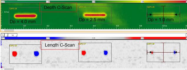
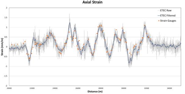
and strain are interchangeable parameters using the magnetoelastic coupling principle.
The ETEC Geo system utilises a minimum of 16 probes, equally spaced around the pipe circumference. This configuration allows the detection of large-scale geohazard events (1 m to several hundred metres) producing mainly axially oriented load in the pipeline. This bi-axial measurement produces a strain grid of 1 in. x 1 in., measuring both longitudinal and circumferential strain values. To fully assess geohazard events, the system is designed to work in both gas or liquid mediums and includes a combination of technologies, such as caliper measurement for high-resolution pipeline geometry (ovalities, dents, buckles, or wrinkles). The geohazard system is also equipped with an IMU to measure bending strain (or movement in run-to-run analysis) and provides pipeline mapping. The eddy current sensors, not requiring a MFL magnetiser, can be deployed as a standalone system or in combination with ultrasonic or acoustic resonance technologies.
Market readiness
The ETEC Geo system is currently undergoing multiple validations on commercially operated pipelines which have been subjected to geohazard events. Following discussions with operators, suitable geohazard sites have been selected to evaluate the technology based on the extensive strain condition knowledge of the pipelines. A combination of stress amplitude, events with specific length, and available information (e.g. strain gauge data) make these pipelines ideal candidates to inspect.
Knowing your assets
Eddy current has been used commercially in various industries to identify differences in steel properties, such as hard spots during the manufacturing process. Pipe grade identification is another application where a measurement of the homogenous pipe properties is taken along the length of a pipe joint.
The eddy current measurement principle is capable of distinguishing material properties, making the ETEC technology a suitable candidate to measure pipe grade. Pipes can be grouped into different pipe types based on their outside diameter, wall thickness, seam weld type, pipe tally information and, more importantly, magnetic response.
The newly introduced Mega Rule requires pipe grade identification on
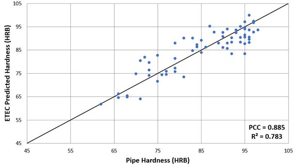 Figure 1. ETEC Geo validation result comparing strain gauge datasets provided by a pipeline operator. ETEC Geo results, axial strain, output is visible in blue and strain gauge in orange.
Figure 2. Unity plot showing ETEC hardness prediction.
Figure 1. ETEC Geo validation result comparing strain gauge datasets provided by a pipeline operator. ETEC Geo results, axial strain, output is visible in blue and strain gauge in orange.
Figure 2. Unity plot showing ETEC hardness prediction.
44 World Pipelines / APRIL 2023
Figure 3. C-scan data showing crack length and depth from pull testing.
Wax-Tape® #1
Anticorrosion Wrap:


A very durable wrap that uses a thick, non-stitch bonded synthetic fabric and has no clay fillers, so it stays conformed to irregular profiles. The wrap requires no abrasion blasting, can be backfilled immediately and is compatible with cathodic protection.
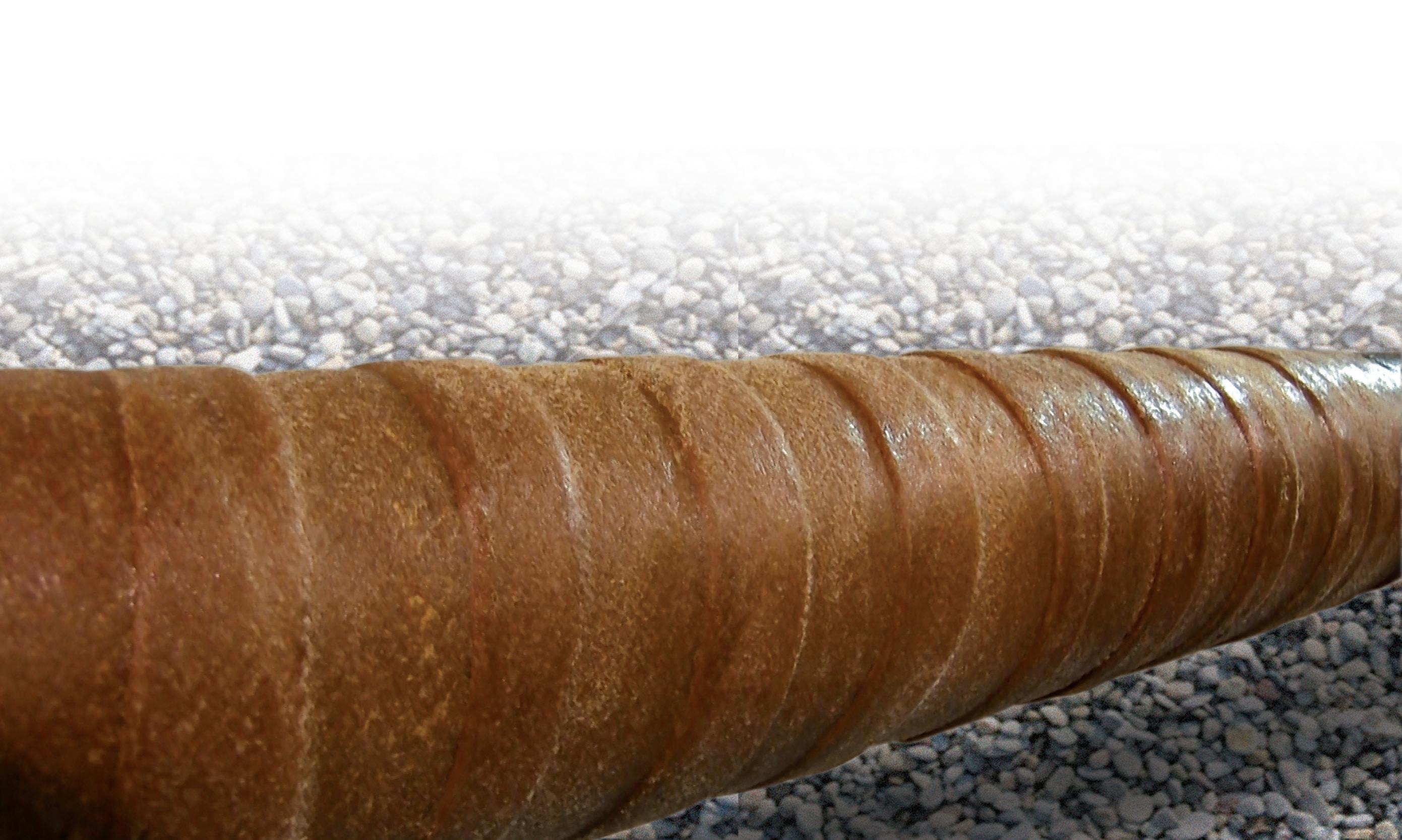

Wax-Tape® #2
Self-Firming Anticorrosion Wrap: A unique, microcrystalline-wax-saturated wrap that slowly firms up to provide excellent above and belowground protection. Comes in a variety of colors and usually requires no outerwrap.
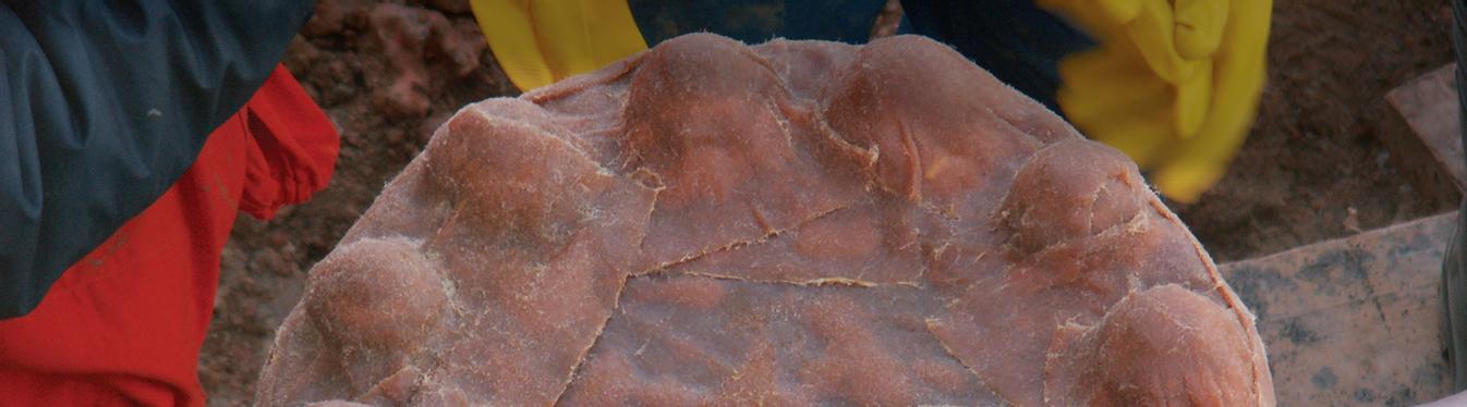
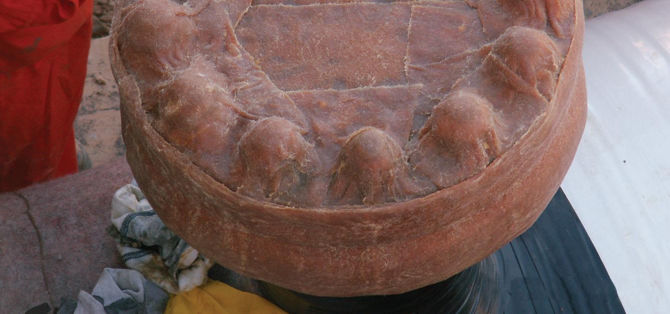
Wax-Tape® HT-3000
High-Temperature Anticorrosion Wrap: Designed for operating temperatures up to 230°F (110°C), Wax-Tape® HT-3000 wrap can be used on high-temperature oil and gas piping, on compressor status discharge piping, beneath thermal insulation and in high ambient temperature conditions.
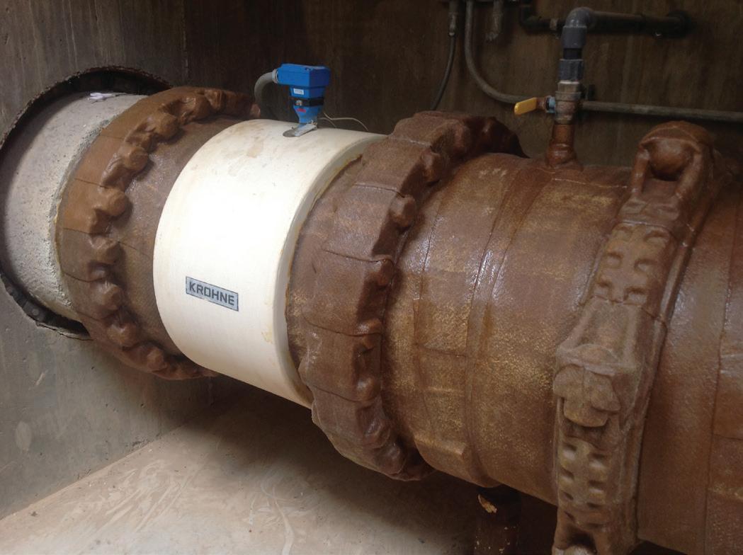
High-quality, easy-to-apply wraps that protect irregularly shaped fittings and require minimal surface preparation.
Only Trenton offers Wax-Tape® brand anticorrosion wrap systems, with primers, wraps and outerwraps.
THE MOST SOPHISTICATED DECOUPLER IN THE WORLD

certain pipelines in the US. ETEC can measure various magnetic properties such as yield strength, chemical composition, or hardness. As such it is likely that a pipe grade identification using ETEC will predict the pipe grade based on these various measured parameters.
To achieve true values, we completed hardness testing using a conventional mechanical indenter on a range of available pipe. Results were compared to the predicted hardness based on the magnetic response using the ETEC technology. Using adequate measured magnetic parameters, one can predict pipe hardness with a satisfactory level of confidence. Hardness is a well-known parameter that is related to ultimate tensile strength. We can define pipe grade with these measured parameters.
Material identification is not only valuable in the context of pipeline traceable records. Validating pipe grade in a pipeline is an important prerequisite for fitness for service assessments prior to converting the lines for products such as hydrogen or CO2
Repurposing pipelines for hydrogen transportation
Decarbonisation of our energy infrastructure is an important topic in our industry for environmental, financial, and geopolitical reasons. In Europe, the transmission of hydrogen through existing natural gas pipeline infrastructure will play a key role in this decarbonisation effort.
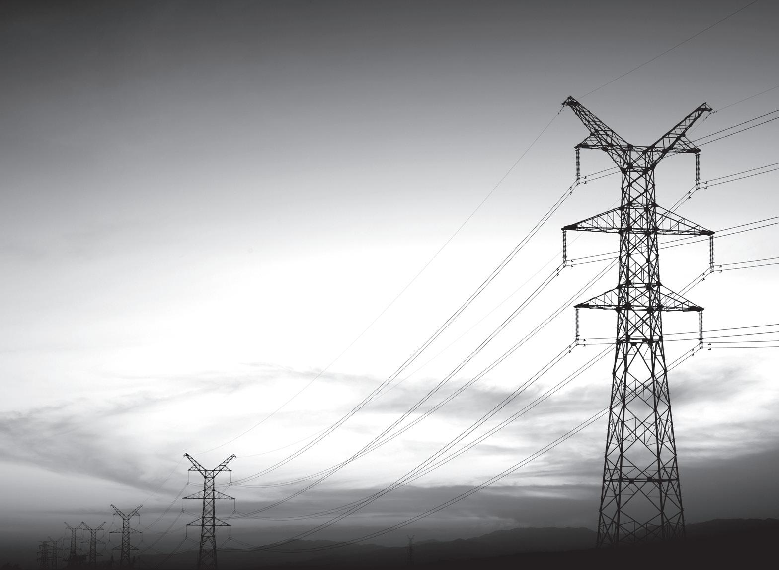
Introduction of hydrogen (either as a blend or pure) will introduce new pipeline failure modes, necessitating new ILI technologies. These new systems will be used to perform baseline surveys before the introduction of hydrogen and in service inspections to monitor any changes thereafter.
Cracks are a major threat to pipelines; as such the industry has devoted a great amount of effort to address the detection and sizing of cracks in the external surface of liquid and gas pipelines. On the external surface, cracks can take the form of stress corrosion cracking (SCC) in the pipe body, fatigue cracks, or defects resulting from the manufacturing process in the welds
Eddy current is one of the most suitable approaches to accurately detect and size internal surface cracks of hydrogen pipelines. Current development efforts are focused on a prototype tool to be deployed in pull test scenarios. After a successful prototype, a validation tool providing full circumferential coverage will be built and evaluated in both a test loop and operator pipelines before fully deploying ETEC for internal cracks.
 Figure 4. ETEC internal crack detection prototype tool.
FEATURING CAMOUFLAGE TECHNOLOGY
Scan to watch our on-demand webinar, Overcoming capacitive effects on interrupted surveys with PCRX technology
Building on Dairyland’s proven history of industry-leading product lines, the PCRX® represents the next technological leap forward in decoupling technology. Using a sophisticated design, the PCRX’s new camouflage technology renders it virtually invisible to interrupted survey testing making it easier than ever to protect and maintain your CP system.
Figure 4. ETEC internal crack detection prototype tool.
FEATURING CAMOUFLAGE TECHNOLOGY
Scan to watch our on-demand webinar, Overcoming capacitive effects on interrupted surveys with PCRX technology
Building on Dairyland’s proven history of industry-leading product lines, the PCRX® represents the next technological leap forward in decoupling technology. Using a sophisticated design, the PCRX’s new camouflage technology renders it virtually invisible to interrupted survey testing making it easier than ever to protect and maintain your CP system.
Abhinandan Arya, Vice President, Head of Technology – Solutions, Synspective Inc., Japan, discusses cost-effective pipeline area monitoring using radar satellite, AI, and cloud technology-mix solutions.
imiting the loss of oil and gas supplies is a critical issue for the entire global energy infrastructure sector, but monitoring an entire pipeline network is difficult. One response to the ever-growing need for a more cost-effective pipeline monitoring solution uses synthetic aperture radar (SAR). This exciting new technology has been proven to provide a comprehensive alternative to
conventional monitoring methods currently used for pipeline monitoring within the oil and gas industries.
Overcoming the challenges of conventional monitoring methods
One of the key challenges faced by pipeline owners is that they often cross difficult and remote areas, which are

47
sometimes large in area and located in harsh environments around the world. Monitoring thousands of kilometers of pipe in these conditions makes regular monitoring dangerous, expensive and sometimes even impossible. Because of this, monitoring using satellite technology has become a promising and viable option that offers a low-cost but effective solution.
Conventional surveying techniques like levelling or GNSS sensor placement have traditionally been used for detecting and measuring land displacement or subsidence. However, these survey methods are restricted to in-situ monitoring capability (observing only one of a limited number of locations). Satellite surveying is a powerful technique for the observation of land surface displacement trends over time.
SAR satellite technology makes it possible to monitor for land deformation around pipeline structures from space. SAR systems measure distance variations between ground targets and the antenna of the sensor in the SAR satellite by repeatedly emitting a radar pulse along the orbit of the satellite, and measuring echoes received from each emitted signal.
Using interferometric analysis over SAR images (InSAR) information about ground displacement down to distances as low as 1 mm is possible to be collected. SAR images contain information about the radar wave omitted by the active sensor in the satellite, which is then reflected by the Earth’s surface and recorded in each SAR satellite data pixel.
InSAR processing generates information on ground displacement in millimeter detail across a wide area. The regular availability of SAR data makes timely monitoring for wider regions more cost-effective than in-situ measurement. Additionally, by comparing new images with a library of previous images, it is possible to find out where and how previous land movements occurred. Apart from small ground changes like land displacement, SAR images can also be utilised for the greater extent of ground changes. The context can include changes like a sudden slip of the land, or damage/changing of the ground surface’s structure due to various factors (man-made or natural).
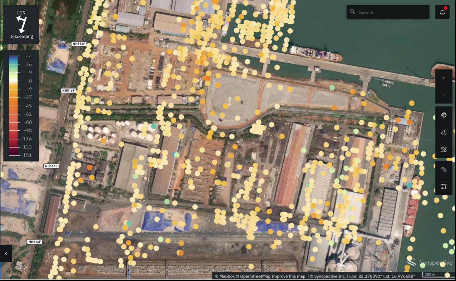
Land displacement caused by tectonic, seismic, and volcanic activity, ice and rock glacier motion, slope instability, and subsidence caused by ground water pumping, mining activities, hydrocarbon extraction, and natural compaction/settlement can be studied with this method. A major advantage of this technique is its two-dimensional spatial coverage as compared to point-wise measurement techniques, such as levelling and GNSS.
Land displacement monitoring at oil storage tanks
Displacement information SAR is delivered as a displacement data point. Each data point represents a specific location (latitude and longitude) and contains historical trends of land displacement value (in mm) at a certain timestamp
48 World Pipelines / APRIL 2023
Figure 1. Image showing displacement data around Kakinada oil storage tank (Source: © Mapbox © OpenStreetMap Improved the map | ©Synspective Inc.).


throughout the analysis period, as well as annual land displacement velocity (in mm/yr).
The coastal front of Kakinada city in Andhra Pradesh (India) houses several petrochemical and agro-oil storage complexes. Figure 1 shows how the displacement data around one such storage tank infrastructure at one of the oil storage tank facilities. Generally, the tanks used for storing oil are cylindrical and mounted on a concrete foundation. The foundation of these tanks is subjected to settlement and subsidence due to several factors such as ageing, loading and off-loading of crude oil, geological and geodynamical condition of the site, and other environmental factors. Monitoring the safety of such tanks then becomes critical as any catastrophic failure will lead to adverse environmental impacts. Figure 2 provides preview of sample land displacement monitoring analysis in which it shows the distribution of displacement points identified as unstable/ moving points over the region.
Clicking each displacement point displayed will show the time-series trend of displacement at the target location across the time of the analysis period. The information is displayed as a graph, which also contains information of annual displacement velocity/rate, either calculated for the entire
analysis period, or calculated over customisable range (e.g. halfa-year, three months, etc.).
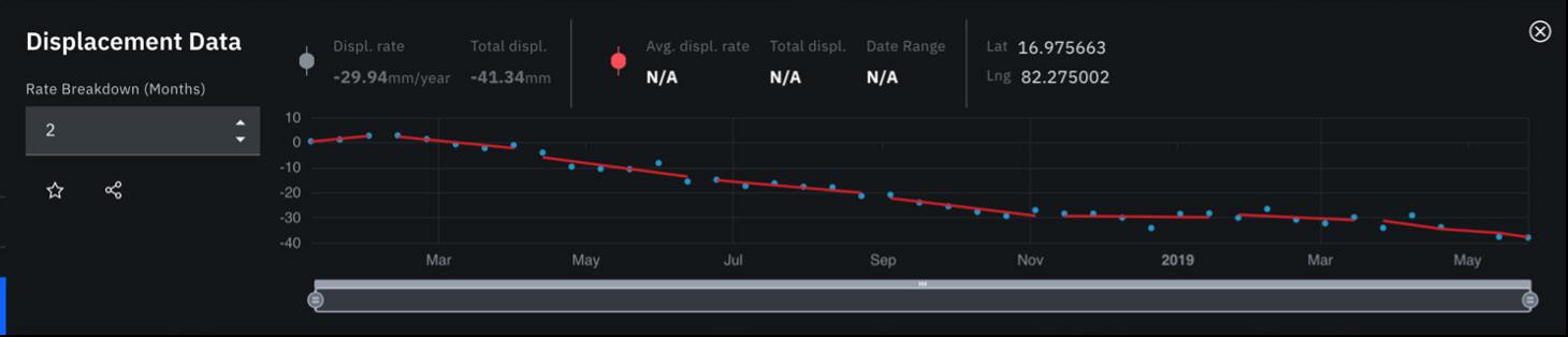
Figure 2 shows a tank experiencing subsidence at the rate of 3 cm/yr. Once this has been discovered, further analysis to discover other locations likely to suffer the same can be done. You can also work out when the displacement started, which can help identify what caused it and helping plant owners to put preventative measures in place to stop it happening again.
Furthermore, oil and gas pipeline networks are also vulnerable to ground movements due to landslide, fault ruptures, liquefaction and subsidence, as well as anthropogenic activities such as subsurface fluid extraction or injection. Subsidence induced settlement has vertical and horizontal components. Out of the two, the buckling forces on the pipelines caused by horizontal displacement is more critical (as it may cause pipeline ruptures), than the bending stress caused by vertical soil settlement. With climate change the tendency for subsidence is slated to increase due to droughts and groundwater pumping. InSAR-based land deformation monitoring is thus very well-positioned to assess the health of oil and gas network assets in a wide spatial area at a high temporal frequency.
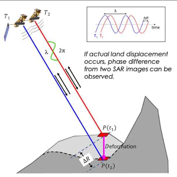
Beyond land movement
By using InSAR technology combined with cloud-based data platforms, business managers within the oil and gas sector can also use the data created for a range of other purposes, including monitoring reservoirs, checking risks from subsidence at offshore facilities, and monitoring the impact of injection and extraction, especially in underground gas storage and operations. It can even help with validating company compliance with health and safety regulations.
By combining AI, data science and cloud technology, InSAR-based monitoring can be taken to an even more advanced level. AI technology enables automation of the data analysis process, speeding up the delivery of information and updates. The data science part enables identification of areas most prone to displacement around the pipeline environment after the attainment of comprehensive situational awareness from InSAR analysis results. Lastly, cloud technology allows for easier data management and processing. The cloud utilisation also takes an important role in the provision of a user-friendly monitoring platform, helping users quickly achieve a well-informed decision-making process for minimising lifetime cost in pipeline infrastructure management practices.
Figure 2. Data table on displacement data around Kakinada oil-storage plant (Source: © Mapbox © OpenStreetMap Improved the map | ©Synspective Inc.).
50 World Pipelines / APRIL 2023
Figure 3. Illustration of InSAR process from 2 SAR images.
THE PIGGING PROFESSIONALS
Boar Pipeline is a full service pipeline solutions provider. Our goal is to provide quality pipeline cleaning and maintenance services and exceed your expectations.
PIPELINE PIGGING
Boar keeps an extensive inventory of pigging products in stock that can be shipped to your job location quickly. Custom pigs can be expedited in order to meet your deadline.
SERVICES
When you contact Boar Pipeline, you will speak with an industry expert who will answer questions and provide solutions immediately. Our representatives are available 24/7.
CHEMICALS
With our own in house chemical company (Houston Chemical), Boar Pipeline can provide all the chemicals for your next project.
CONSULTING
With more than 40 years experience in the pipeline service industry, our consultants can design a custom pigging program specifically for your pipeline.
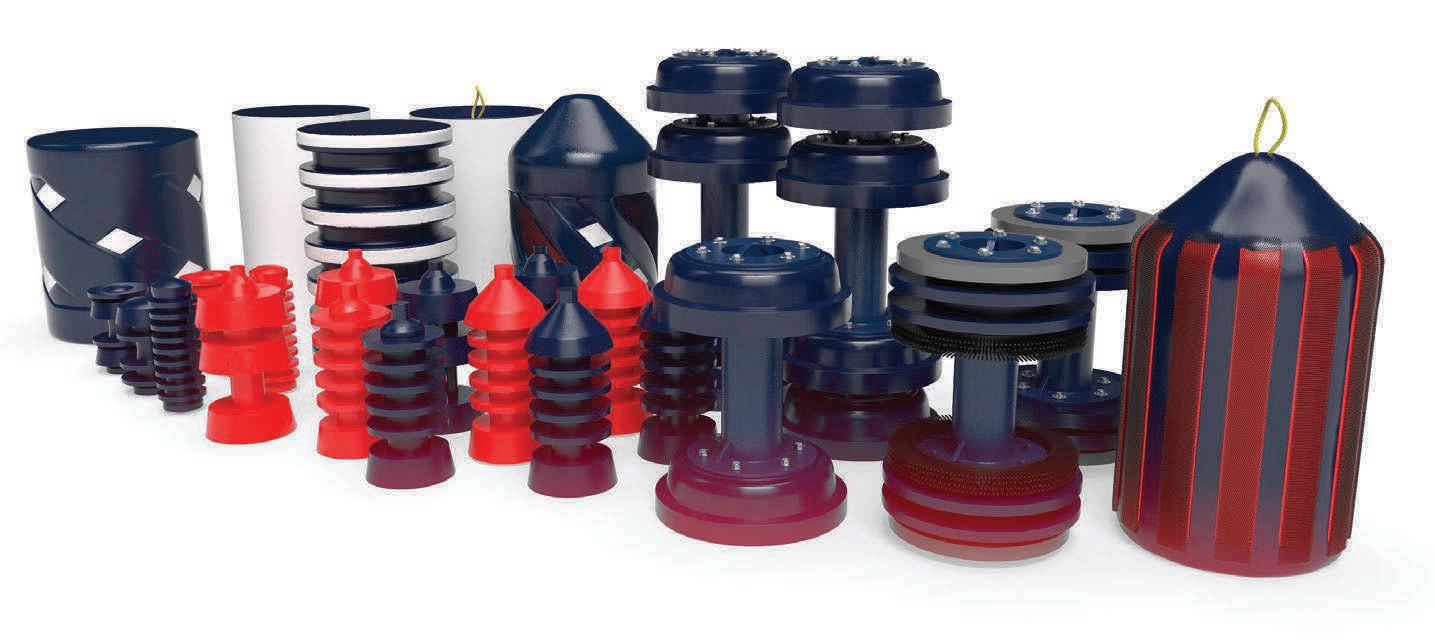
Boar Pipeline • 41095 Park 290 Dr. • Waller, TX 77448 (281) 469-9355 • BoarPipeline.com • sales@boarpigs.com
Above and below - Indonesian Buaya Besar Barge 1.2 m to 20 m depth.
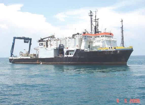
Brasil Post Trenching Rough Shore Approach (Lead Keel Machine)
Above and below—Ultra shallowwater system 0.6 m to 3 m depth.
Typical Deck Layout On DP Vessel for Deep Water Trenching 80 to 400 meters
Post Trenching in rough swells off Brazil. Cutter Suction
TRENCHINGCAPABILITES
Above and below - Indonesian Buaya Besar Barge 1.2 m to 20 m depth. Above and below—Ultra shallowwater system 0.6 m to 3 m depth.
OES INTERNATIONALLOCATIONS

Above and below - Indonesian Buaya Besar Above and below—Ultra shal system 0.6 m to 3 m depth.
Above and below - Indonesian Buaya Besar Above and below—Ultra shal system 0.6 m to 3 mdepth.
First Trenching by Dynamic Positioned Vessel 1992 New Zealand
• Trenching in largest Seas 28 ft 1992 New Zealand

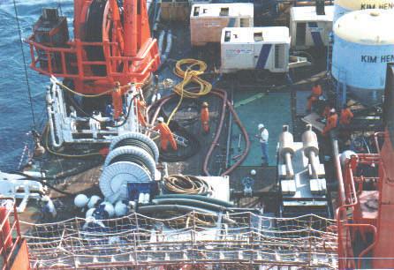
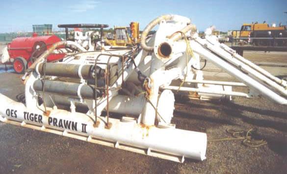
• Trenching Hardest Soils with proprietary high pressure system 150 kpa shear strength Thailand 1993
First and only Post Rock Trencher ‘Tiger Shark’ 1994 to 2008
•
• Trenching Deepest Pipelines 400 meters 1999 Bass Strait
Trenching Deepest trench 7 meters 2000 Indonesia
• Trenching in strongest water current 11 knots China 2004
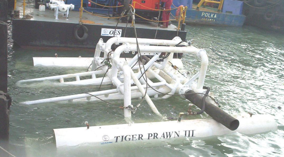
Busan, Korea
Trenching Stress Relieving of Directional drilled pipelines by others Australia 2004
• Trenching Live Gas Pipelines Indonesia 2006
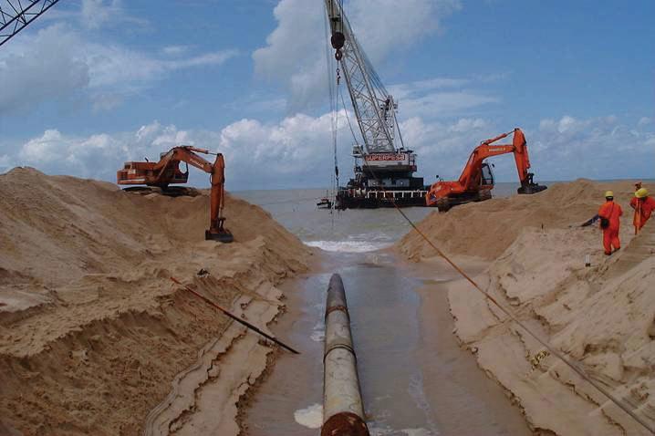
Singapore
•
• Trenching roughest shore approach with pumps on beach Ghana, Africa 2018
Rio
. •
• •
Balikpapan, Indonesia
Also laid 7 kilometers of 150 NS 110,000 Volt cables including directional drilling shore approach through rock cliffs
Salvaged six projects where pre dredging, directional drilling and jet sleds failed
• •
Melbourne, Australia Corporate Headquarters
Equipment Includes: 45 20 ft sea freight containers with 8 x 1600 hp 350 psi pumps, 2 x 1000 psi booster pumps, 3 hydraulic hose reels with 90 to 120 meters of 4 x 4 inch hose, interconnecting piping and suction strainers, 6 x subsea pipeline lead k eel type jet machines for 6 inch to 52 inch pipelines, 1 Tiger Shark cuts 600 mm deep trench per pass x 1200 mm wide in 30 mpa ucs rock, 2 cable trenchers that simultaneously backfill to 1.5/3 meters cover. An eight point mooring system 20 tonne, 20 tonne heave compensator, 3 Hydraulic power packs including 1 300 HP for tiger Shark, 1 Tiger Shark Hose reel with 2 x 500 meters of 5000 psi hydraulic hose and a 10 tonne clump weight and deployment system. A 10 tonne hydraulic cable tensioner.
Company Value 1995 to 2014 $100 million. Sell now $5 million or best offer. Ask for photos, specs, container lists and completed project references.
1 305 304 6452 www.oes.net.au lincolnoes@aol.com
De
Largo, USA
Janeiro, Brazil Key
Seychelles Islands INTERNATIONAL OIL, GAS AND POWER EPC CONTRACTOR
working off DP vessels
Diverless Systems
working off DP vessels
Post Trenching in rough swells off Brazil. Cutter Suction
DP vessels
Cutter Suction Dredge
vessels
Post Trenching in rough swells off Brazil.
Above and below - Indonesian Buaya Besar Above and below—Ultra shallowwater system 0.6 m to 3 m depth.
OES World Leader in Subsea Pipeline Trenching Is For Sale (all assets tangible and proprietary intangible) Track Record since 1992 includes the successful trenching of over 250 pipelines and cables including the following world’s firsts:
• Largest Pipeline 54 inch 1995 India
World’s deepest water post trencher sled 1200 ft
Typical Dynamic Positioned Vessel during Trenching (Lead Keel Machine)
Inter Tidal trenching in mud flats 1.2 m to 20 meters (Lead Keel Machine)
Floating Jet Sled across mud flats too shallow for barge
The powerful combination of IoT sensors and satellite connectivity can transform unpiggable pipelines into a valuable data source, says Tom Krikke, Commercial Director,

orldwide, there are about 3.5 million km of pipeline across 120 nations – and that’s just the oil and gas sector. There are probably about the same again for the water sector. The majority are in the US (65%), followed by Russia (8%), and then Canada (3%). Inspection, repair, maintenance (IRM) is a hot topic in the industry right now. And, especially for the ageing 3.5 million km, gaining better insights into their condition is essential to manage risk exposure.
Historically, pipeline pigs have been the tool of choice for maintaining pipelines and ensuring their continuous operation. Regular pigging maximises fluid transportation by removing scale build-up, controlling internal corrosion by removing internal debris, and collecting pipeline data such as temperature, elevation, wall thickness, and anomalies. Typically, pigging a pipeline involves a launcher and a receiver, and the insertion of an intelligent pig into the pipeline system. The pig travels some distance with the flow of the pipeline’s contents and is then extracted at the receiver.
As we all know, pipelines basically fall into three categories: gathering lines, transmission lines, and distribution lines. In the case of gathering lines (the focus of this article), it is interesting to note that many were not built for easy inspection. In fact, roughly 40% of all pipelines are difficult to pig, or ‘unpiggable’.
What makes a pipeline unpiggable?
Of course, while it’s travelling along the pipeline, the average pig gathers a lot of data, mostly relating to the shape and the wall thickness of the pipeline, which in turn yields clues about the status of the pipeline and its integrity. However, pipelines that are not optimally designed may prevent effective pigging.
Physical characteristics of the pipeline – such as very tight bends, dead ends, sudden changes in geometry, or the presence of a valve – may prevent passage of the pig. Other pigging challenges relate to operational conditions. For example, there may be insufficient flow to push the pig forward, or the pipeline may be too old and fragile to withstand the pressure needed to actually run the pig.
But without the data gathered by pigging, operators are essentially flying blind. And as all operators know, in the gathering pipeline world, risk management requires an accurate assessment of threats and consequences. In other words, can a potential cause (a threat) create a particular event, and might that event lead to a consequence? We need to understand and quantify threats, and that is why accurate data is so critical.
On the one hand, we think in terms of IRM (optimising control of the pipeline – prevention of risk). And it’s here where we need as much data gathering as possible so we can understand what is happening. On the other hand, we think in terms of how to minimise the consequences of a threat manifesting as an event through emergency pipeline repair systems (EPRS).
When you consider the enormous distances and the remote terrain that gathering pipelines traverse, it becomes clear that implementing a robust risk assessment methodology requires a continuous improvement
HiberHilo, Netherlands.
53
cycle that cannot be achieved with pigging alone. To achieve that, it is essential to automate data collection on remote gathering pipelines.
Data collection: the high cost of frequency
To better understand a pipeline’s threats, we need accurate data in five key categories: pressure, vibration, flow, valve positioning, and temperature. Additionally, to properly manage our risk assessment, we need reliable data with as much frequency as is economically feasible.
As we consider the topography and enormous distances that are characteristic of remote gathering lines, it’s clear that collecting this data will be costly and difficult. Even if we have the resources to assign the required highly trained technical teams and valuable equipment (often helicopters and off-road vehicles) to gather this data, we will struggle to capture this data as often as we’d like to quantify our risks.
For that reason, over the years, many operators have turned to systems that can digitally monitor these locations, typically using terrestrial cellular networks and fibre optics. While they are an improvement over manual methods, these systems tend to be costly and have associated limitations such as proprietary, expensive hardware, and a lack of infrastructure to support a viable network across long distances in remote areas.
Satellites on the horizon
For all the previously mentioned reasons, using terrestrial systems to sample reliable data at the required frequency in remote locations has always been expensive and unreliable. But, what about satellites? Until about 10 years ago, satellite connectivity was expensive, but that cost has plunged recently. This has coincided with the IoT – data gathering via miniature sensors connected to an IP address. Each IoT sensor is battery-powered and connected to a satellite gateway over an energy-efficient long-range network (LoRaWAN).
Each gateway has an 8 km connection range, which enables the distribution of numerous sensors along that segment of the pipeline. As for power, the gateway itself can run on either the local grid or solar power. Once the gateway has retrieved sufficient data from the sensors in the field, it streams it up to the satellite network, which then downlinks it to a central data centre. From there, the data can be integrated into any operator’s internal systems.
What data can be captured?
Recent technical developments with IoT capabilities have opened the door to the collection of a vast array of data types. Let’s start with pressure. The HiberHilo pressure sensor, for example, can measure pressure between 0 - 1000 bar (0 - 14 500 psi), and is rated to be installed in hazardous areas. It is protected against dust and water ingress (rated at IP65 or IP66), and temperatures between -20 to +59˚C.
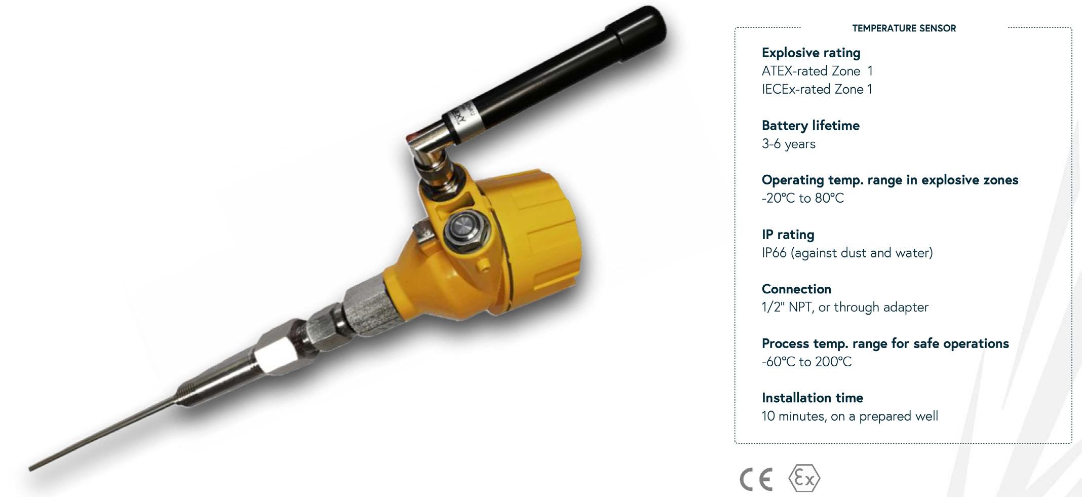
Normally, it is programmed to sample pressure every 15 minutes and then transmit data to the gateway every hour (although it can be set to sample every five minutes and transmit every 15 minutes). Depending on the sampling rate, its internal battery lasts from three to six years. Installation is easy – normally in under 10 minutes by the operator. And because installation is fast and simple, a sensor can initially be installed on a pipeline, and then later moved to another section of pipeline or another pipeline entirely. This ease and flexibility of installation allows for a wide range of applications.
Temperature is another key data variable that indicates the status of a pipeline. The HiberHilo temperature sensor has similar environmental characteristics as the pressure sensor, and it can capture and transmit process temperatures between -60 to +200˚C.
In addition to pressure and temperature, there are a wide range of other crucial parameters that can provide a detailed picture of the status of a pipeline. These include flow, vibration,
54 World Pipelines / APRIL 2023
Figure 1. HiberHilo temperature sensor.
HDPE piping systems for intakes & outfalls
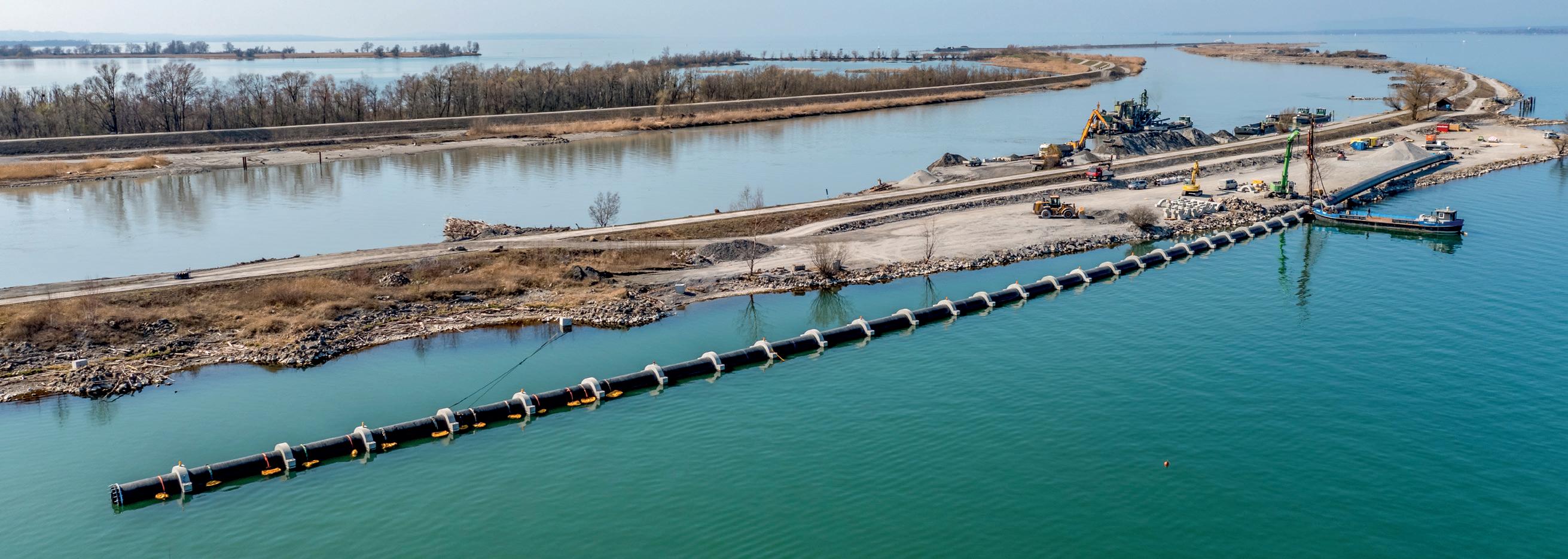
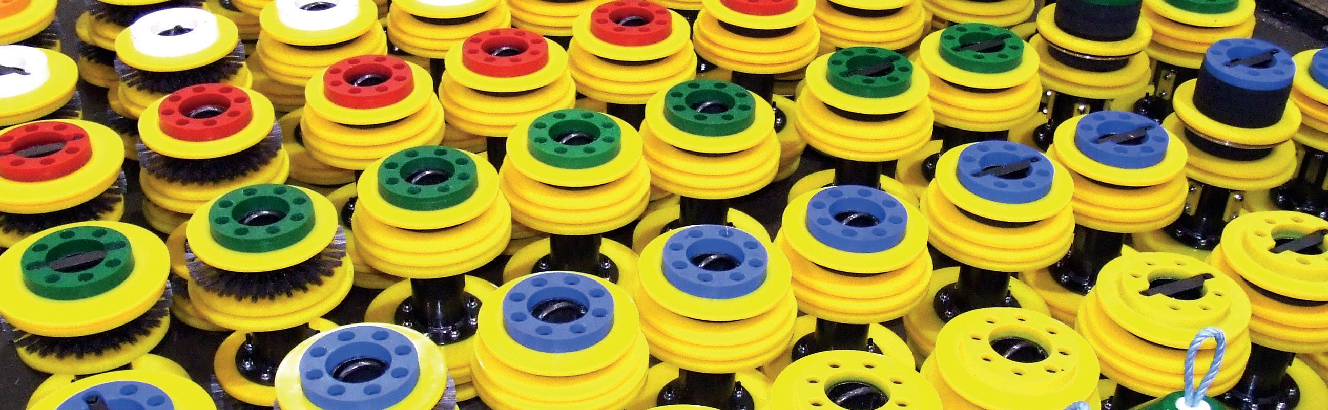
• OUTSTANDING LIFE SPAN
• FAST AND EASY INSTALLATION
• FOR HIGH-VOLUME FLOWS
• HIGH-QUALITY MATERIALS
• EXPERTISE IN PLASTICS PROCESSING
• Propipe provides a suite of services to ensure a successful project including full pipeline review, cleaning pigs and Trident SMART gauge.
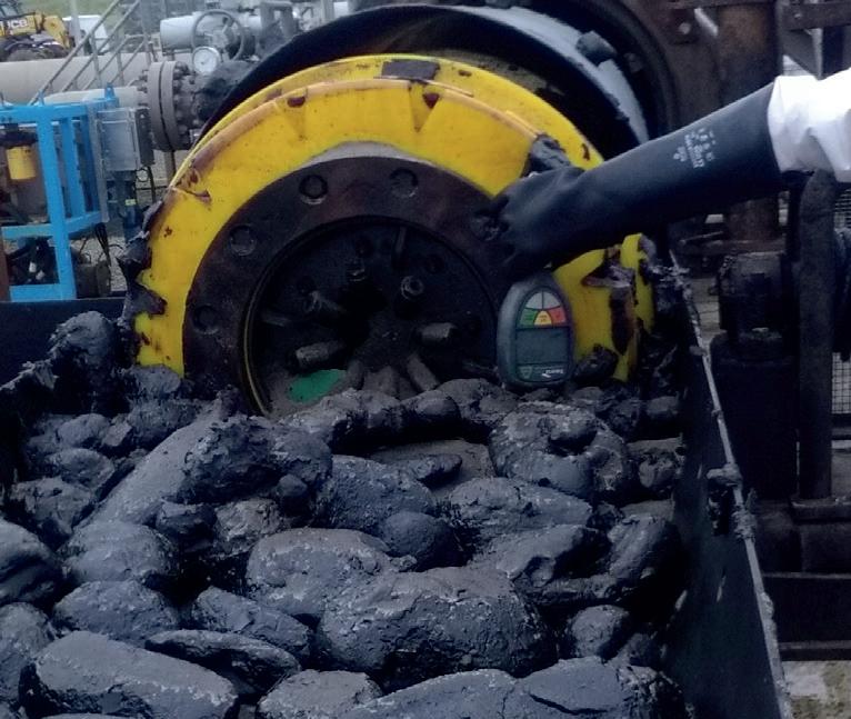
• Propipe pigs all designed pipelinespecific for best performance.
• Trident pig tracking and APEX AGM plus SMART Gauge and Datalogging for full data assessment.
pigs for operational maintenance or pre-inspection cleaning Propipe Limited Queens Meadow Business Park, Hartlepool, England TS25 5TE T: +44 (0)1429 872 927 E: groupsales@propipe.co.uk Propipe North America 302 Bluewater Road, Unit 2 Bedford, Nova Scotia B4B 1J6 T: (902) 417 5075 E: sales@propipenorthamerica.com propipe.co.uk LinkedIn
Custom
CLEANING
SMARTER PIPELINE
AGRULINE
PIPES
XXL
Kunststofftechnik Gesellschaft m.b.H. | Ing.-Pesendorfer-Strasse 31 | 4540 Bad Hall, Austria | www.agru.at | Bild:
agru
Stiplovsek Dietmar
valve position, pump status, and the detection of specific gases, such as methane.
For these parameters, HiberHilo offers a plug-in adapter that converts any analogue sensor output of 4-20 mA or 0-5 V into a LoRaWAN signal. This significantly expands the range of operating parameters that can be monitored remotely: flow, methane detection, variable speed drive (VSD) readings, torque, voltage (for example, to ensure cathodic protection is intact), and more. As for the satellite gateway, it collects signals from as many as 100 sensors within an 8 km radius. It runs on 24V DC or can be solar-powered, and can be installed anywhere within 90 minutes.
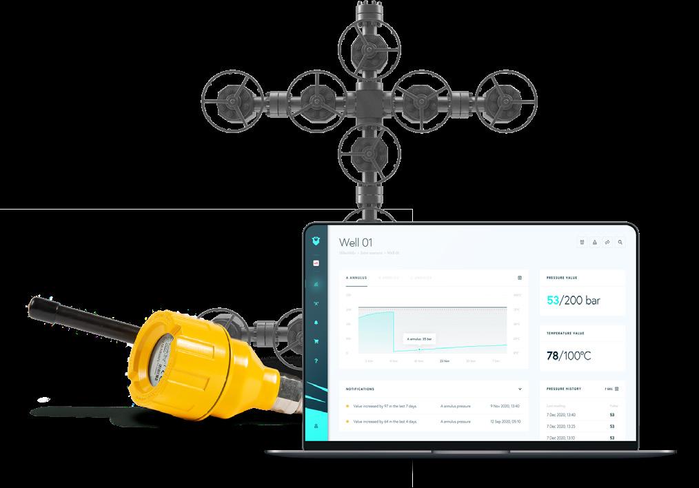
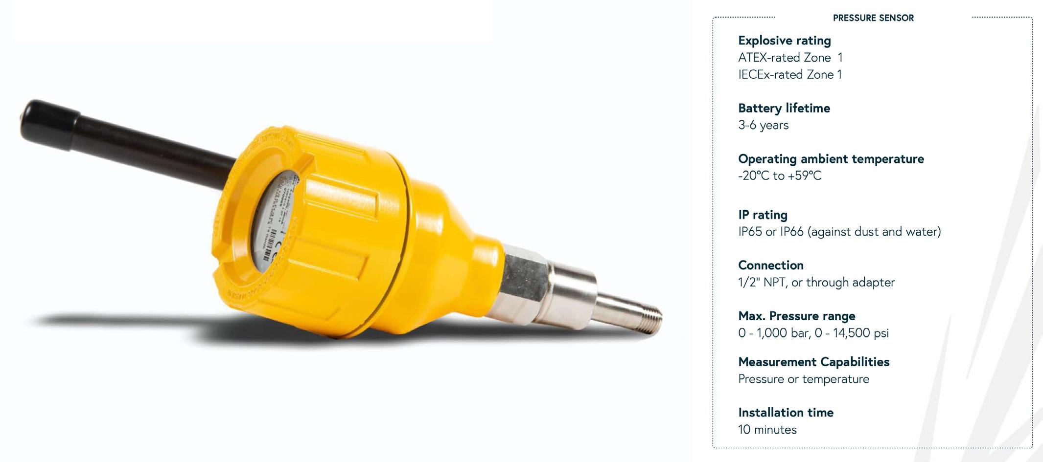
Data security is of course paramount these days. All HiberHilo internal protocols and practices have been audited by an independent third party and certified for SOC 2 TYPE II compliance.
Subscription model and rapid implementation
Contrary to many other IT solutions, the HiberHilo solution requires zero CAPEX. A HiberHilo subscription includes all the
hardware (the sensors, the connectors, the gateway) needed to monitor remote gathering pipelines. It also includes the data connectivity from the sensors to the gateway, the satellite connectivity, as well as the integration into your data systems. The HiberHilo SLA guarantees the delivery of 95% of all data to the operator’s system. Lastly, the implementation time is measured in weeks, not months – typically around seven weeks.
More data means better decisions
What can you do with more data? Most pipeline operators already have a process information management system (PIMS) system in place – from the very simple to the very complex – to optimise operations, prolong lifecycles, and prevent incidents. By adding more accurate and frequent data, specific alerts can be implemented to supplement and enhance a PIMS methodology.
For example, a drop in flow rate or pressure could indicate there’s a leak somewhere – and even where it is. Additionally, by tracking pressure over time, an operator can ensure they are not exceeding specified operating pressure envelopes on different pipelines. This type of ‘exception’ data provides a warning that something may be wrong and enables a wide range of operational alerts that can mitigate the risk of threats. Lastly, improved affordable pipeline monitoring isn’t just for operational pipelines. One important use case is that of pipelines that connect abandoned wells or soon-to-be abandoned wells. It can be hard to justify the significant expenses of dispatching crew to inspect them, but these pipelines represent a real threat.
Quantifying and assessing risks is crucial, and to make the right decisions, you need as much data as possible. With the right sensors installed, an operator can detect leakages and activate an appropriate field response. And now, thanks to the combination of satellite connectivity and IoT, operators can accurately monitor remote pipeline assets to gain a complete picture of their risk profile.
56 World Pipelines / APRIL 2023
Figure 3. HiberHilo dashboard.
Figure 2. HiberHilo pressure sensor.
NEED A DRIVING FORCE FOR YOUR PIPELINE PROJECTS?
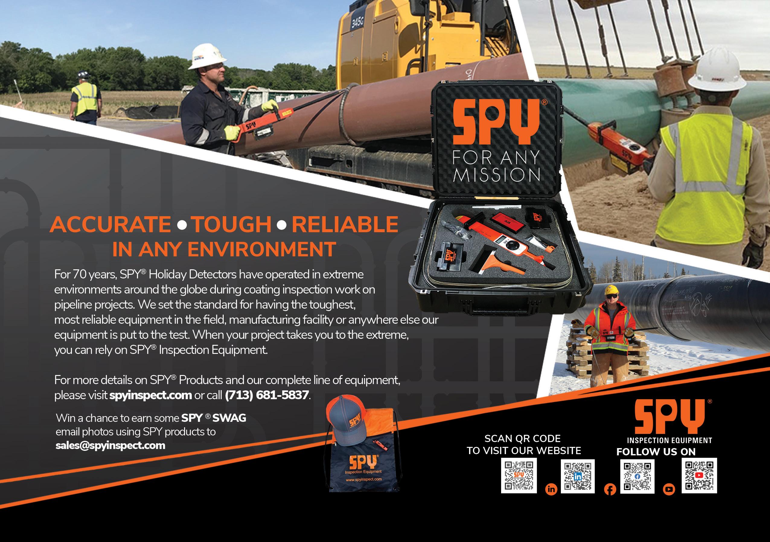

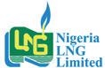


Be part of the largest global natural gas, LNG, hydrogen, low-carbon solutions, and climate technologies industries exhibition and conference to take place in Asia in 2023. Shaping the future of energy Held in Gold Sponsors Partner Sponsors Supported by Organised by Co-Host SCAN TO BOOK YOUR STAND gastechevent.com @gastechevent #Gastech 40,000+ Attendees 750+ Exhibitors 300+ Ministers, CEOs, and business leaders speaking 4,000+ Delegates 750+ 300+ 40,000+ 4,000+ Attendees Exhibitors Ministers, CEOs, and business leaders speaking Delegates Shaping the future of energy Co-Hosts Organised by Held in Supported by Partner Sponsors Gold Sponsors Gastech Energy Club Official Partner SCAN TO BOOK YOUR STAND Be part of the largest global natural gas, LNG, hydrogen, low-carbon solutions, and climate technology industries exhibiton and conference to take place in Asia in 2023. gastechevent.com @gastechevent #Gastech
ydrostatic testing of subsea pipelines is essential for the early detection of leaks. Failure to identify and rectify pipeline leaks can have obvious operational repercussions, but also incur financial penalties in recognition of the potential environmental damage that a leak could cause.
One approach to leak detection is to add dye to the water during hydrostatic testing. Any dye that escapes from the pipeline can be detected by ROV or diver. For larger leaks it is sufficient to illuminate the dye to stimulate it to fluoresce, then observe the result with the human eye. The OceanTools DyeLighter® range of leak detection lamps use high intensity LEDs to stimulate dyes in this way. The human observation process can be augmented using a dye detection camera such as the OceanTools C3-DDC, which contains filters tuned to the specific wavelength of the light emitted by the illuminated dye. This should allow leaks to be detected more easily, but still ultimately relies on human judgement and subjectivity.
Detecting smaller leaks is far more of a challenge as they may not be visible to the human eye even when fluoresced using a DyeLighter. OceanTools set out to develop a world-leading dye detection system with this in mind, combining their in-house skills with worldleaders in optical technology from Aberdeen University (UK). With an accelerated development programme, the OceanTools DyeTector® range of optical detection systems emerged just six months later and includes the D7 ROV mounted detector, D9 diver held detector with integral display, and the D10 which can detect all three widely used dyes. As the industry moves towards the greater use of AUVs, OceanTools have reacted by developing a DyeTector specifically for integration onto an AUV.
The DyeTector uses advanced optical techniques that shine an intense, focussed, light through a series of lenses, filters and diffusers onto a dye, causing it to fluoresce. The fluorescence is then detected by a sophisticated detector unit comprising filters

and an advanced photomultiplier with the ability to identify light down to single digit parts per billion of dye dissolved in water. The presence of dye is clearly and unambiguously represented digitally and displayed by surface software or diver held display. The performance of the DyeTector is greatly superior to that of any other optical leak detection system and typically one hundred times as sensitive as the human eye. Smaller dye dosing ratios are required as a result.
To date, there have been three main dye types in use for subsea leak detection, classed as rhodamine, fluorescein and ultraviolet. DyeTector systems are available to detect any of these classes of dye, including the latest D10 developed with three sets of optical components to detect the three primary dyes using a single compact device.
Fluorescein is progressively being phased out due to its significant environmental concerns, and environmental regulations continue to be strengthened in Europe and beyond. To address this, OceanTools are introducing a new dye to market named C-Dye ECO. It has been developed to comply with new substance in solvent (SIS) regulations, ensuring that all components including the dye substance have the required biodegradation characteristics. This is supported by the roll-out of a new D7 DyeTector system with optical components to suit the new dye.
Case study
OceanTools were approached by an Azerbaijani oil company, UBOC, to assist with the commissioning of a new pipeline. A successful leak test was undertaken at stable pressure and temperature and at a relatively shallow depth of 60 m.
Kevin Parker, Managing Director at OceanTools said “We worked closely with the customer to provide the best solution for their requirements with the client choosing to use the D8 DyeTector
59
Kevin Parker, Managing Director, OceanTools Ltd, UK, introduces an optical leak detection system that is typically one hundred times as sensitive as the human eye.
along with OceanTools C-Dye 370 UV dye. The DyeTector and C-Dye performed flawlessly together so another successful job and another happy customer!”
The customer, Ian McLeod, Commissioning Manager of UBOC said “The original intent was to dewater into a purpose-built lagoon and then transport the pipeline hydro test water away to be disposed of. The cost of the lagoon would be US$1 million. As we finalised the design and construction, we realised we didn’t need to add a chemical cocktail into our hydro test water but we did still need to add a sea dye. We looked into dewatering the marine pipeline into the Caspian at landfall but the Caspian Region Ministry of Ecology and Natural Resources (MENR) would not permit us to add a normal fluorescent sea dye which typically is a fluorescent green, so we had to find a clear sea dye, and that is where OceanTools came to our rescue in providing not only the colourless sea dye but the ROV mounted detection equipment. OceanTools kindly agreed to supply us with a sample of the dye that was tested in Baku, and found to comply fully with local rules and regulations as required by MENR. I cannot say anything but good about the advice in product selection, service, product, and detection equipment supplied by OceanTools”.
A video showing the D8 DyeTector in operation is available at to view online.1 The footage provided by our customer UBOC shows the discharging of the 20 in. pipeline hydro test water at a depth of 60 m. Shown in the video is the purge of the dye solution from the pipeline, carried out to check the correct functioning of the DyeTector. The excitation of the dye is clearly visible at the point where the purge water intersects with the ray of UV light.
Rentals
In 2022, Ashtead Technology, an international subsea rental equipment and solutions specialist, signed a rental agreement with OceanTools to be the exclusive rental partner for OceanTools’ DyeTector systems, including the latest D10 DyeTector®.

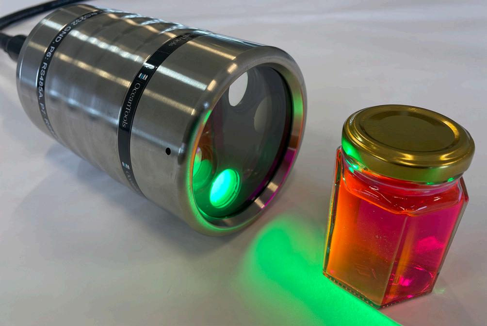
Dave Johnston, ROV Tooling Manager for Ashtead Technology, said: “The exclusive agreement with OceanTools builds on our inventory of leak detection equipment for underwater survey and inspection operations. It also demonstrates our ongoing commitment to the global offshore energy market by offering the latest and most technologically advanced technologies to support our customers’ projects worldwide.
“OceanTools systems have been performing well in the field and delivering excellent results for our customers.”
References www.youtube.com/watch?v=kJ9hAjLTr6U&feature=youtu.be
Figure 1. D10 Three dye DyeTector with a sample of C-Dye.
espite the immense progress in transitioning to explore green energy alternatives, the increasing demand for change in the global energy industry faces new obstacles associated with the construction, maintenance, regulation, and integrity of assets. Safety, reliability, and efficiency are essential to meeting the demands of the industry and must be at the forefront of operational decisions when faced with these challenges. Maintaining asset integrity without the risk of disruption to operation or safety and environmental incidents directly impacts these decisions, and is vital to ensuring the appropriate solution is selected so that assets can perform efficiently and sustainably.
With over 20 years of experience, Wellube is leading the way for reliable, efficient, and safe engineering solutions to manage asset integrity. As a global engineering specialist and pipeline maintenance expert, Wellube works with the top players in the oil and gas industry, and has supported all leading national oil companies across the UAE, Qatar and India. Part of global innovators in subsea technologies and engineering, Unique Group, Wellube offers specialist engineering products and services for flow management intervention and integrity, turnkey valve reliability management and onsite precision machining to the global oil and gas, renewables, power, petrochemical, and infrastructure industries. Its portfolio of services includes hot tapping, line stopping, online leak sealing, online safety relief valve testing, online valve flushing, lubrication and sealing, and onsite precision machining services. With over two decades of industry experience, the team’s technical expertise and engineering capability allows them to support complex projects and solve critical problems in minimal lead time.
Running heavily on pipelines, both onshore and offshore, operators in the oil and gas industry

have a responsibility to maintain the integrity of their assets to avoid any loss of containment due to ageing or corrosion that could have lasting impacts on the operation, and more importantly, the environment. As the industry transitions to incorporate sustainable operations, the demand for innovative solutions has highlighted that safety and efficiency are more vital than ever before.
Assess, seal, deliver
Wellube’s online leak sealing process can be applied to a range of pipelines, valves, and pressure vessels across the petrochemical, oil and gas, power generation, gas distribution, and nuclear industries. Featuring a custom-designed leak clamp, its leak sealing services are underpinned by stringent compliance with a range of procedures and practices to ensure safe and efficient solutions. Online leak sealing has a proven track record on steam, water, hydrocarbons, and a variety of other chemical systems, and can withstand pressures from vacuum to 8500 psi, and temperatures from -320°F to 1800°F.
A recent project for a leading national oil company in Qatar required the repair of a flare line with multiple sections indicating corrosion, utilising a 2.9 m 24 in. enclosure. After performing an inspection of their pipelines, the client found large, corroded sections of the flare line and, during operation, the leak from the piping system could have led to the escape of line medium into the atmosphere, potentially leading to an unplanned and costly shutdown. Criticality of this level could have catastrophic repercussions for both the operation and the environment if it had gone undetected.
The client then approached the team at Wellube to provide online leak sealing to repair the corroded area with no interruption to operation. After thorough assessment and
61
Garry Kidd, Managing Director, Wellube, UAE, shares an insight into a few of the company’s recent pipeline and wellhead projects in the Middle East.
discussions with the client, it was agreed that the installation of an enclosure was the preferred solution to repair the damage.
From the beginning of production to repair the pipeline, there were a series of challenges faced, one of which being multiple changes in the geometry of the pipe which needed to be encapsulated to contain the leak within the enclosure. Due to its size, fabrication of a clamp of this scale proved challenging, and being installed at a high elevation meant there was risk of damaging pipelines below and surrounding the damaged section during installation over a live plant.
Based on the specifications of the site requirements, Wellube’s team of experts engineered a large 2.9 m sectional 24 in. enclosure, weighing around 2 t, to be installed onto the flare line. Manufactured in line with ASME standards, the clamp was designed to withstand temperatures of 390°F (198˚C) and pressures of 0.7 MPA. With the requirement for a quick turnaround due to the risk of causing any delays to operation, the clamp was fabricated in a short priority lead time and successfully installed within schedule. Sealed in place with 100% seal on the enclosure, the client was able to continue operation of the line without a costly shutdown.
Mitigation of risk, improving safety, and reducing the potential cost of production delays is Wellube’s priority, and is a result of its compliance with HSEQ and stringent adherence to international design codes and standards (such as ASME, API, and ASTM) throughout the manufacturing and installation process. This was able to be achieved to the highest of standards.
In the industries ranging from oil and gas to infrastructure, the safety, productivity and cost of operation is directly proportional to asset integrity and continued operational performance. Wellube continues to be at the forefront of executing hot tap and line stop, under pressure leak sealing and pipe freezing across industries globally. We provide an integrated solution for flow management which includes scope and specification development through client interaction, engineering evaluation, design and manufacture, quality and safety testing, and project execution.
A turnkey solution to valve reliability
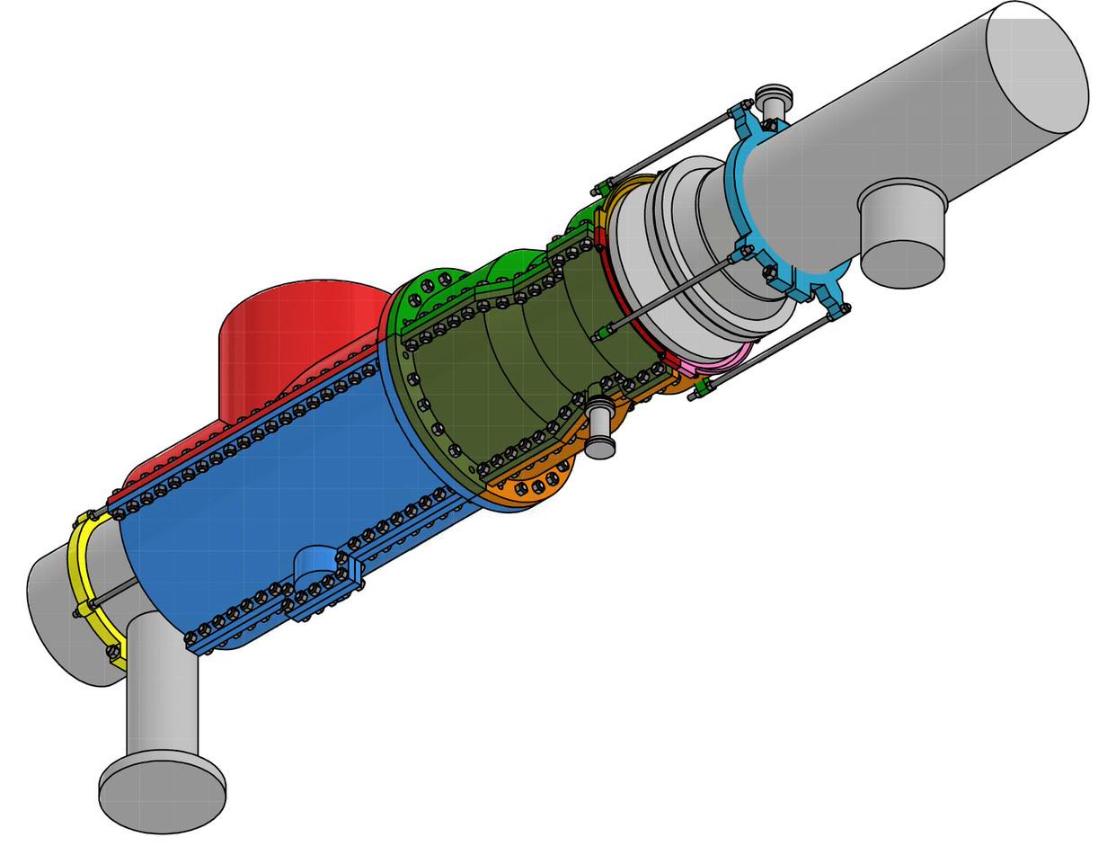
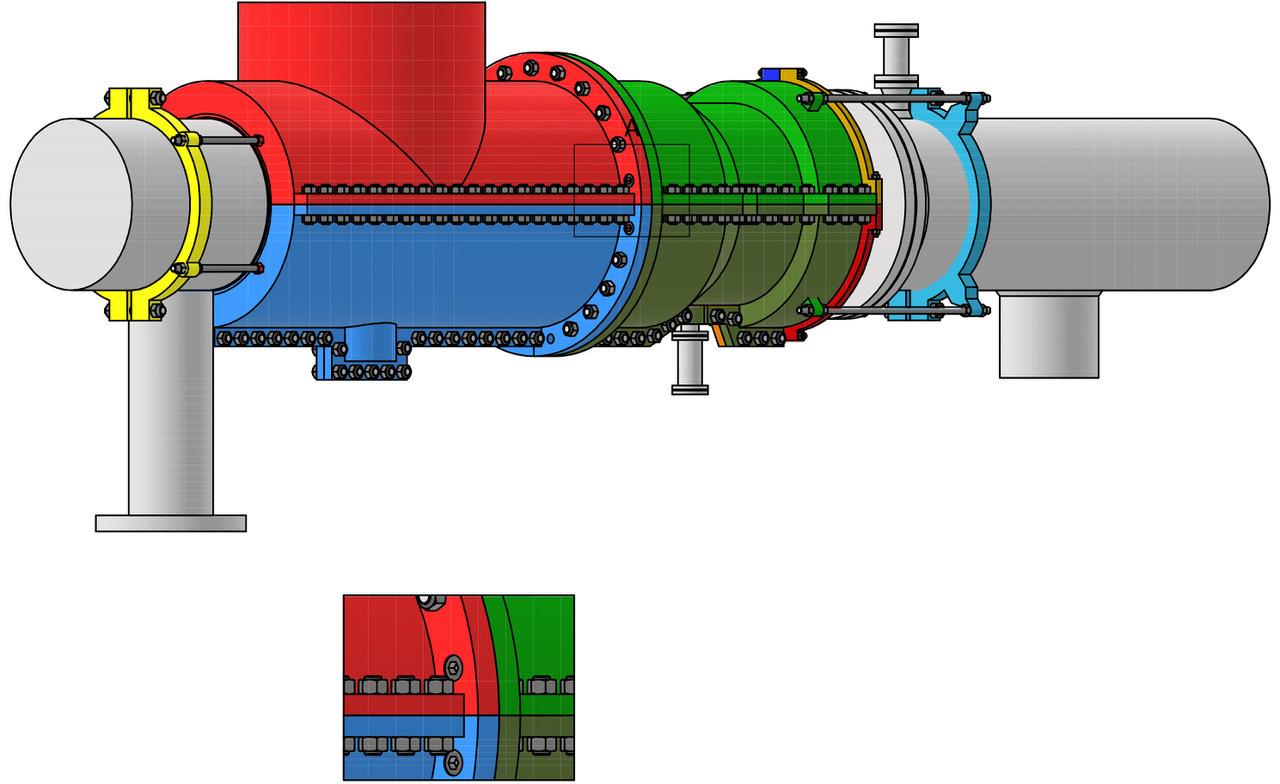
Valve reliability is critical in maintaining production. Having a strong reputation in supporting complex valve maintenance challenges for over two decades, Wellube’s full turnkey solutions can be performed remotely and onsite, creating flexibility for the operator and minimising downtime by avoiding operational delays. The result of stuck gates can leave a well completely inoperable, which can create substantial costs to the operator for the loss of production.
In a unique test of full turnkey gate valve milling capabilities, a recent project for a leading asset owner in the UAE saw Wellube perform high-pressure gate valve milling services to help a client regain full bore access to the wellheads, and restore operations with minimal downtime.
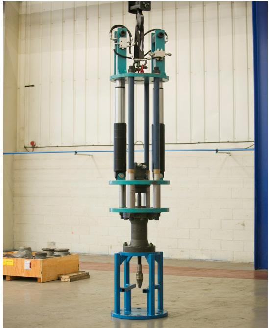
With multiple stuck gates of Xmas trees on its onshore wellheads, the client was faced with loss of production due to its inaccessible assets and approached Wellube for support with the issue. After an in-depth analysis of the challenges at bay, Wellube decided to perform milling on the stuck gate valves of the assets to support the client in restoring operations and oil production.
Throughout the project, there were several challenges associated with the timeline and operational accessibility of the
Figure 1. Wellube designed enclosure.
62 World Pipelines / APRIL 2023
Figure 2. The 2.9 m long 24 in. enclosure which was designed, manufactured and installed in Qatar by Wellube.
Figure 3. Wellube’s gate milling equipment.


D eve l o p e d by t h e i n d u s t r y fo r t h e i n d u s t r y
ADVERTISERS’ DIRECTORY
project. Having gone untouched for a long period of time, most of the wellheads were spread across rough and sandy terrain in a remote location with limited access to support facilities. Due to the nature of the project being turnkey, Wellube’s engineers were contracted to cover all aspects of site requirements including design, development, and supply the correct equipment and facilities. In order to avoid delays, Wellube containerised an office and workshop, and completed multiple milling jobs in a single mobilisation, allowing the work to be completed on time and without delays.
High-pressure gate milling was seen as the best solution for the client based on its ability to drill through the toughest and thickest gates available in the wellhead market. This allowed the client to regain access to the well annulus for stuck gates providing a full-bore access. A total of 32 valves for 23 Xmas trees were milled including the Upper Master and Lower Master valves, along with the delivery of a turnkey project management solution. The experienced technical team covered several wellheads with 2 - 4 in. gates with pressures ranging up to 5000 psi.
With a quick turnaround, the client was able to resume production in minimal lead time and the project was successfully completed with zero incidents due to it being fully HSE compliant.
In conclusion, the technical expertise and stringent adherence to compliance and industry standards allows for fast action to be made to maintain asset integrity without the loss of production and operational time. With safety and efficiency at the forefront of the industry’s agenda, Wellube is leading the way in providing expert solutions that can reduce downtime, prevent harm to the environment, mitigate the risk of safety hazards, extend asset life and maintain the integrity and sustainability of assets across the industry.
Wellube’s success in its reliable, safe, and efficient engineered solutions is a testament to its ongoing commitment to managing and ensuring asset integrity across the global oil and gas, renewables, power, petrochemical and infrastructure industries. Following the pandemic, the company has emerged strong with a commendable order backlog and revenue growth. With its focus set on geographical expansion and technological innovation, Wellube’s strategy for 2023 includes launching new integrated asset management solutions and venturing into new countries while also strengthening its presence in the UAE, Qatar and India.
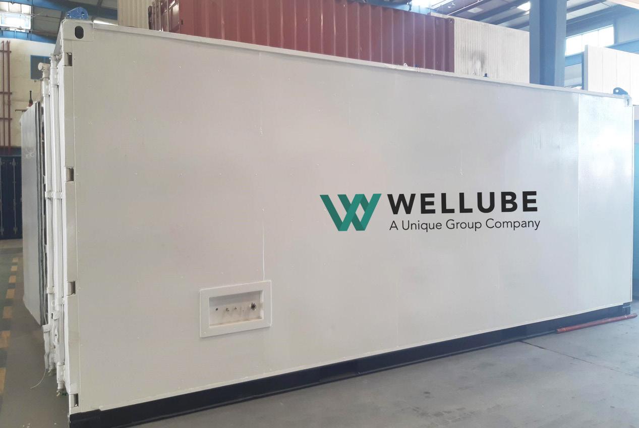
Advertiser Page 3X Engineering OFC, 24 AGRU 55 BAUMA 35 Boar Pipeline 51 CRC-Evans 4 Dairyland 46 Darby 27 DeFelsko 30 DENSO GmbH 33 Denso Inc. 7 E. H. Wachs Industrial Products OBC Electrochecmical Devices, Inc. 20 Gastech 58 Girard Industries 63 Global Energy Show 60 Herrenknecht AG 23 HiFi Engineering 37 Intero 41 LK2 Srl 49 Mokveld IBC OES 52 Pigs Unlimited International LLC 29 Pipeline & Gas Expo 2024 38 Pipeline Inspection Company 57 Propipe 55 Purplewave, Inc. 17 Qapqa 2 ROSEN IFC Skipper NDT 19 SPT 2023 63 Stark Solutions 13 STATS Group 11 Tracto Technik 57 Trenton 45
Figure 4. Wellube’s containerised office and workshop.
Mokveld’s ZERO emission valve.
World First! - No stem seal to atmosphere
Mokveld’s innovative Environmental Sound Technology realizes your net-zero goals:

• GHG Scope 1 reduction: ZERO emission over the full lifetime
• GHG Scope 2 reduction: Extremely low power consumption
• GHG Scope 3 reduction: Low weight and compact design
Reduce OPEX and CAPEX with accurate (servo) control, diagnostic data, reduced LDAR and potentially smaller explosionproof areas.
Step into the (Hydrogen) future with Mokveld, visit: mokveld.com/zeroemission
Achieve net-zero Scope 1 with Mokveld’s
ZERO emission
Mokveld Valves BV, experts in sustainable valve systems.
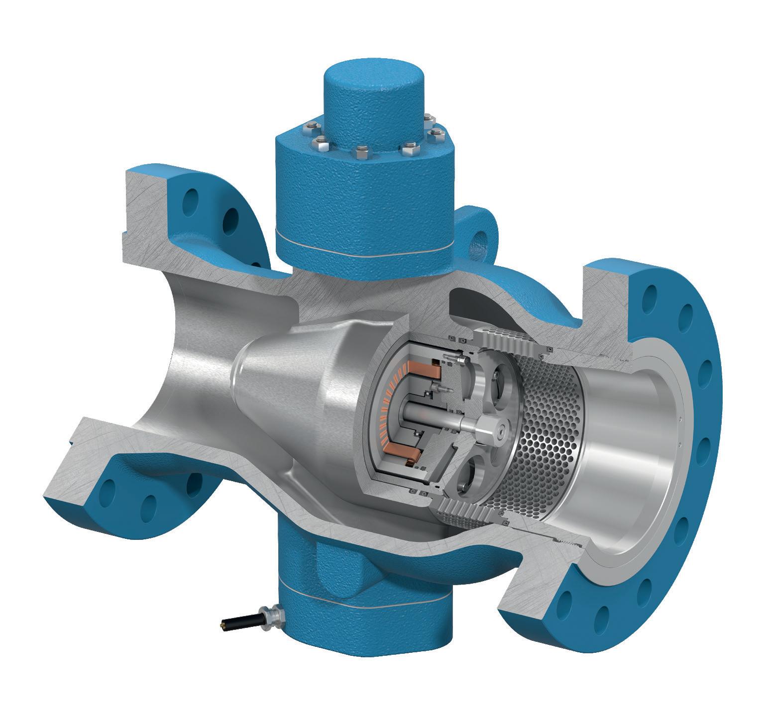
R ZEV
PIPE IS NOT ROUND
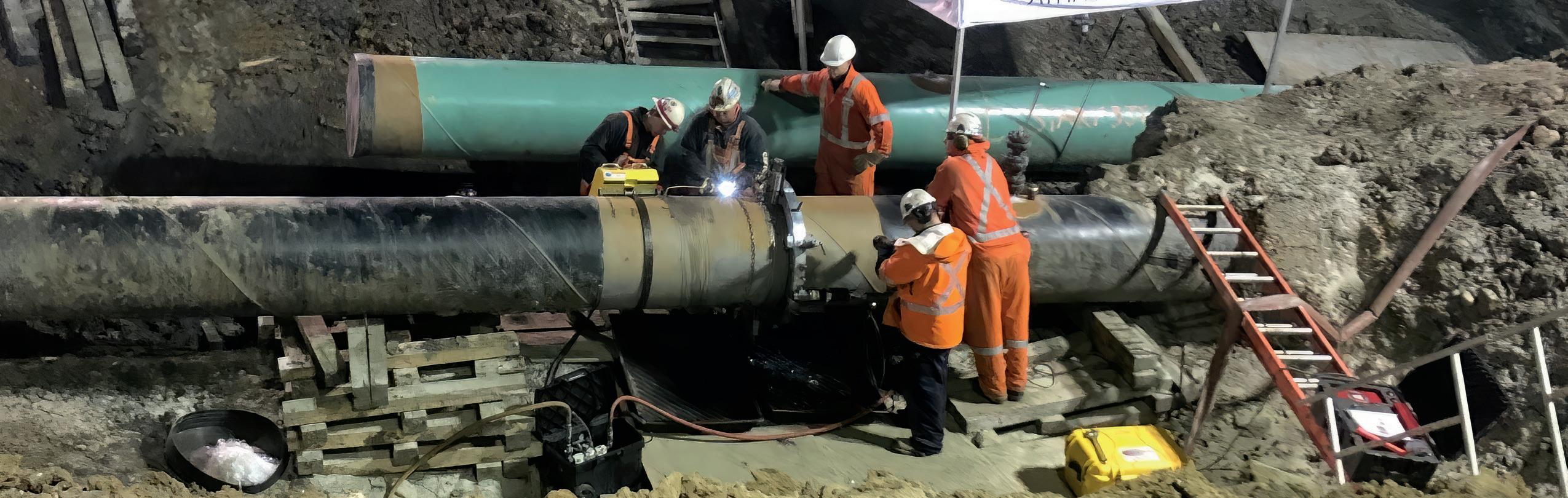
Kits from 6-120 inches (150mm-3m)
Fast Setup & Operation
As you likely know, thin-walled pipe is seldom round and this can make field machining challenging.
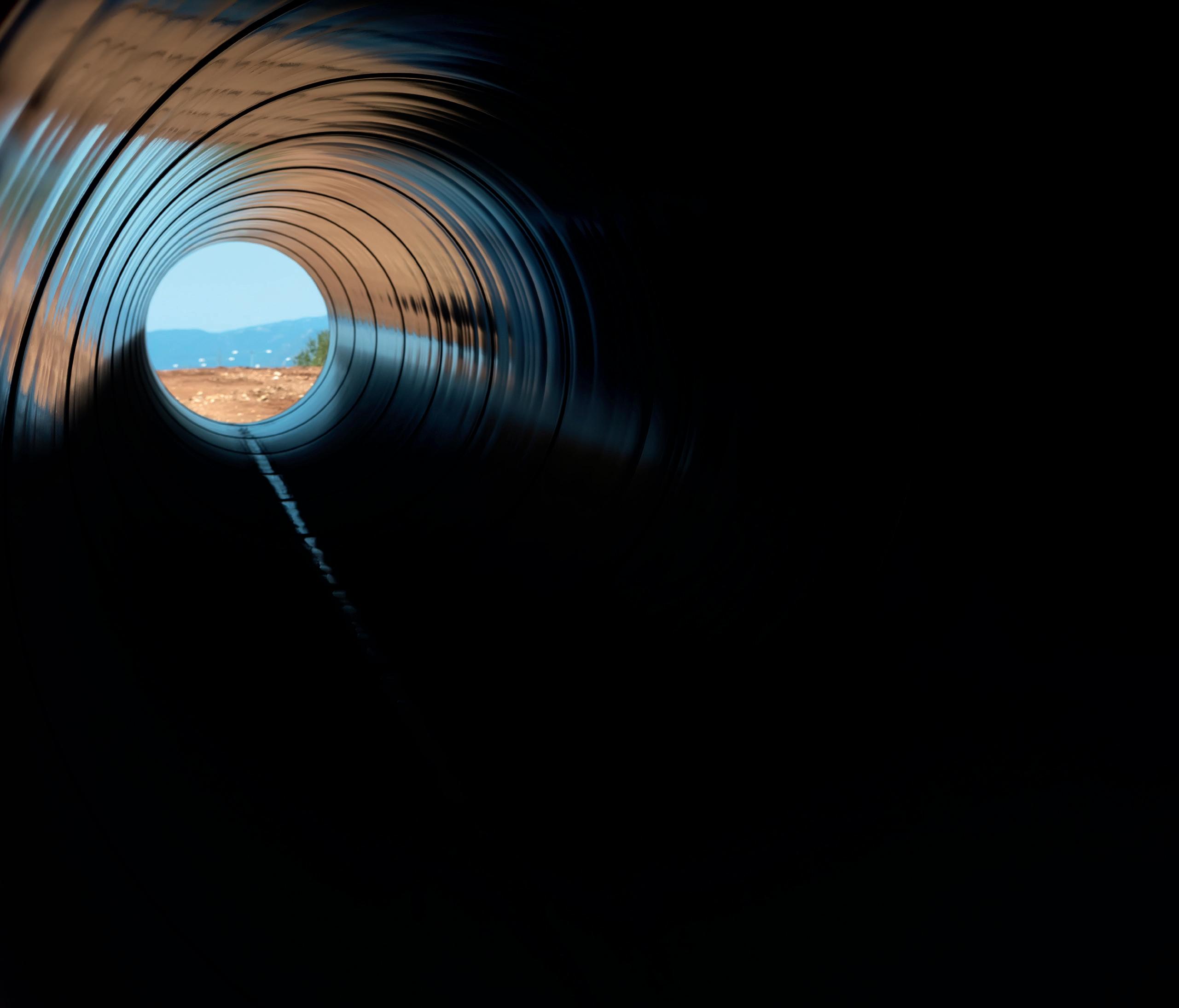
• Wachs DynaPrep split frame pipe cutters are designed for fast setup and operation.
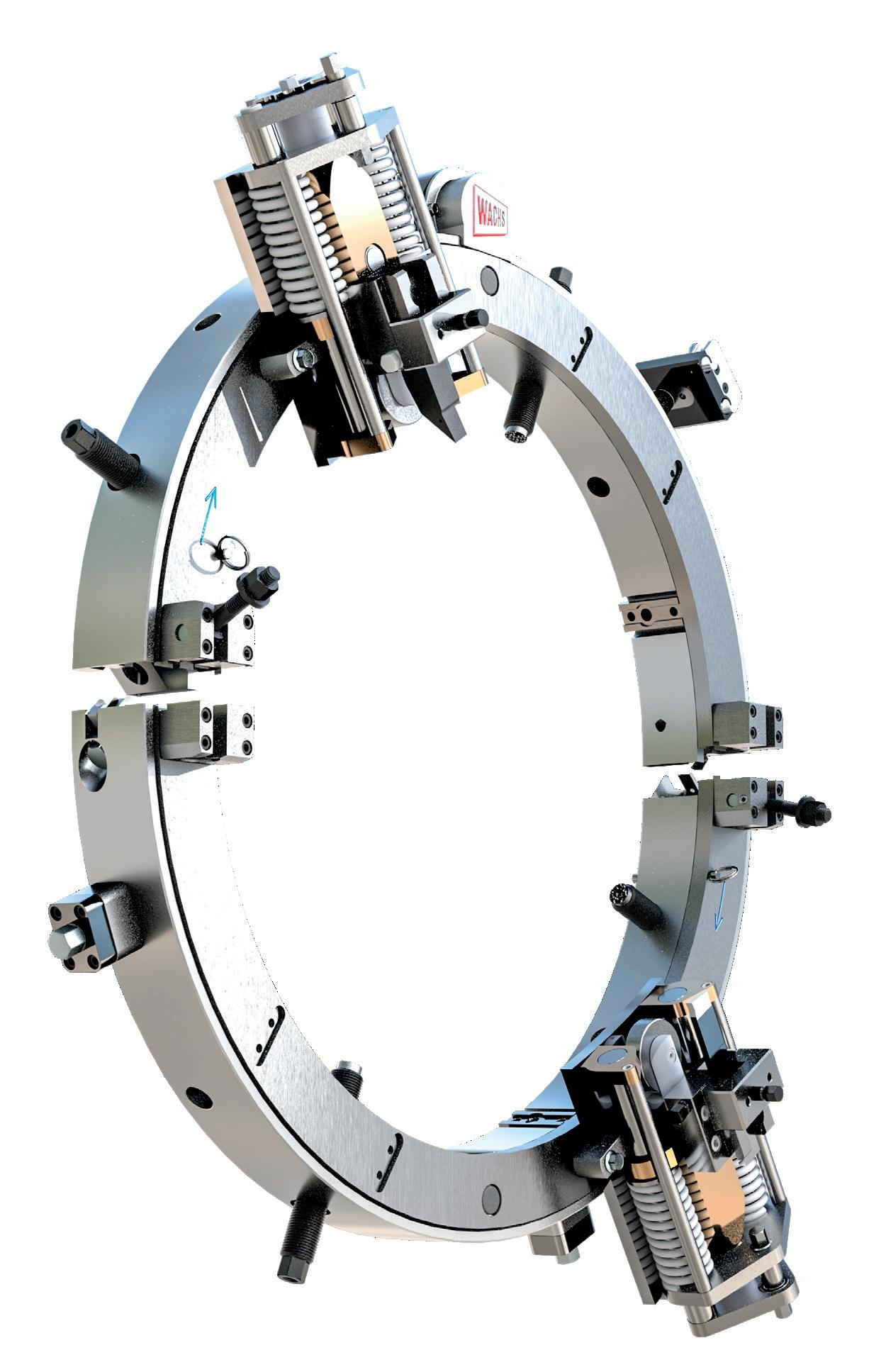
• Pipeline kits for machining out-ofround pipe are available for sizes from 6 to 120 inches.
• The guide wheel on the out-of-round tool slide follows the outside of the pipe while heavy-duty springs maintain tool bit contact and cutting depth making the necessary prep.
• With one machine, you can perform operations from simple cutting and beveling, compound beveling, J preps, deep counterbore and more.
For more information or to schedule a demo, contact your Wachs Representative. Visit
Us Online ehwachs.com/Pipeline
Need it faster? Call (847) 537-8800
SALES OR RENTALS
