7 minute read
Surface elements


Stephen Petit, on behalf of Zetec, details how the latest NDT technologies deliver more accurate pipeline inspections without requiring the removal of coatings.
Inspecting pipelines for material thickness, defects, and weld integrity is one of the most challenging – and common – types of non-destructive testing (NDT) applications in the oil and gas industry. NDT techniques range from simple manual and visual tests to sophisticated technologies that detect and measure surface and sub-surface flaws, porosity, variations in metallurgical structure, corrosion, and a range of other discontinuities in exposed pipelines without having to damage or destroy materials.
While NDT inspections can help pipeline owners ‘see’ what’s going on with their assets, coatings can complicate the process.
For instance, penetrant testing (PT) is a common way to detect surface-breaking flaws such as fatigue and stress-corrosion cracks in metal and other non-porous materials. It involves applying coloured liquid penetrant to the surface and allowing capillary action to draw it into open cracks. The liquid becomes visible under ultraviolet light or by the contrasting color of the dye being used, indicating the presence of defects to the technician.
In a localised area, PT can be affordable and simple to use. However, the process requires chemicals and extensive surface preparation, including the removal of coatings before the penetrant can be applied.
Magnetic particle testing (MT) has similar advantages and disadvantages. With MT, very fine ferromagnetic particles are applied to the material and are drawn into any surface-breaking defects using magnetic fields. MT is only effective on ferrous metals and determining crack depth is particularly challenging. One common practice is to successively buff or grind the cracks until they disappear and then measure the depth of the grind or the remaining wall thickness – at best, it’s a messy and imprecise technique.
Because PT and MT both require a clean, bare metal surface, the time and effort required to remove coatings and field-apply them after the test can erode the simplicity and cost-effectiveness of these techniques, especially when the work surface is large or complex.
Digital revolution In lieu of PT and MT, eddy current and ultrasonic testing instruments, software, and probes can capture and analyse cracks, corrosion, changes in thickness or metallurgical structure, and other defects while leaving protective coatings intact.
Eddy current testing is a widely used technology that can detect surface and subsurface defects in conductive materials. In simple terms, when the technician places a probe or coil to a metal surface, it applies an electromagnetic field which swirls through the material in loops, like eddies in a river. Any defects will alter the flow of electrons; these distortions are captured and analysed by an eddy current instrument and displayed for the technician to review.
Under comparable conditions and with a skilled technician, single-coil eddy current testing and PT will produce comparable pass/fail-type results. However, the newest generation of handheld eddy current instruments, such as the Zetec MIZ-21C, dramatically increase the test speed, accuracy, and repeatability, especially on long weld runs and large inspection areas. These instruments have the processing power, software, and battery life to perform inspections virtually anywhere.
An eddy current tool with a C-scan display can present a digital ‘big picture’ and help inspectors find more defects in less time, and the industry’s more advanced instruments can conduct dual-frequency testing, digital conductivity testing, and non-conductive coating thickness measurement.
Eddy current array (ECA) takes eddy current testing a step further. ECA probes like the Zetec Surf-X flexible array probe family have multiple coils in one assembly, positioned at longitudinal, transverse, or off-axis orientations and firing at coordinated times. Technicians can capture more information in a single pass than conventional, single-coil probes and significantly increase their inspection speeds.
Eddy current testing has the added benefit of generating electronic inspection records for advanced analysis and reporting, a significant advantage over penetrant testing, magnetic particle testing, and other manual techniques. Eddy current results can be saved, shared, stored, processed, and compared at any time.
Indeed, with the right surface array probe, software, and handheld eddy current instrument, an operator can set up an inspection quickly, conduct a test, see results instantly on a C-scan display, and dramatically increase the speed, accuracy, and repeatability of the inspection.
One practical consideration for eddy current testing is that the excitation coils need to be close to the material for accurate flaw detection and signal quality. Probe suppliers now offer flexible probes that allow the coils to stay nominally perpendicular to the material’s surface. In the case of a coated or painted non-ferromagnetic weld, for example, a flexible surface array probe can encapsulate the weld bead, transition zone, and heat-affected zones in a single pass without extensive surface preparation.
Understanding ultrasonics Ultrasonic testing (UT) uses high-frequency sound energy to indicate flaws both on and beneath a coated or non-coated metal surface. Ultrasonic waves enter the material at precise intervals and a set angle, and when a wave encounters a defect, some of that energy is reflected back and generates an echo. The time it takes for that energy to reflect back to the probe is calculated and analysed by a test instrument and presented instantaneously as a graphic on a screen for the technician to interpret.
A conventional or standard UT probe is capable of generating and receiving a single ultrasonic beam. Phasedarray UT systems use probes with multiple elements (typically from 16 - 64) that are excited by an instrument in a highly controlled manner, using a specific delay law and, after reception, the contribution of each element
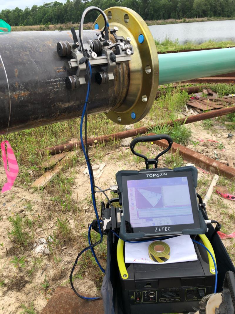
Figure 1. TOPAZ64 pipe weld.
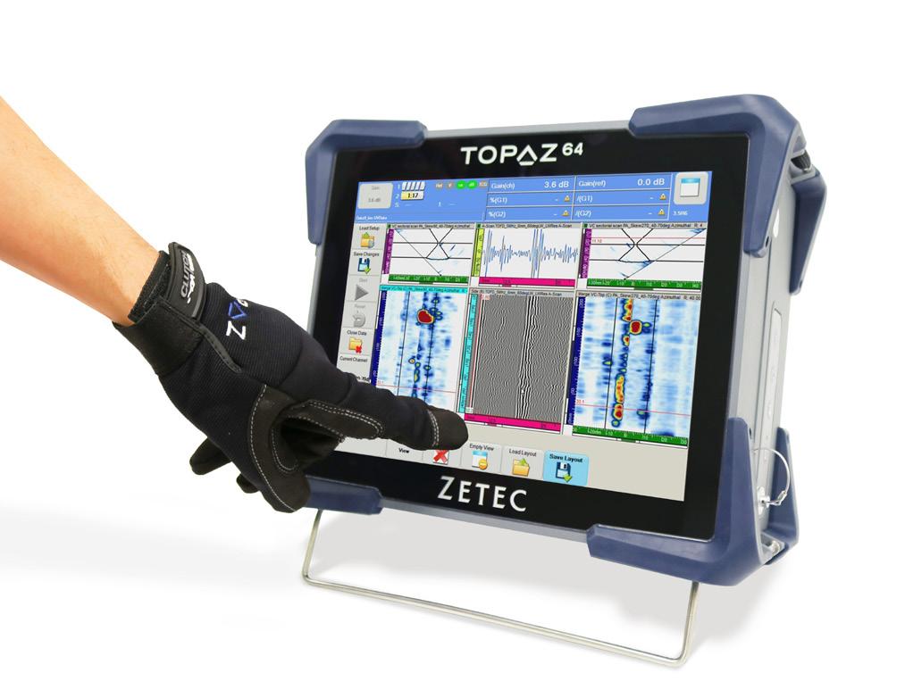
Figure 2. Zetec’s TOPAZ64 gives technicians access to multiple data analysis techniques.
is summed to produce one A-Scan. A phased-array UT instrument can produce a focused beam of ultrasound that can also have different steering angles. This can simplify and improve the inspection of complex geometries and dissimilar materials, which are challenging to test because of the varying acoustic properties the technician will encounter.
The computing power of the latest phased-array UT instruments, including Zetec’s TOPAZ64, gives technicians access to data analysis techniques – and inspection opportunities – that once seemed out of reach. One of these is full matrix capture (FMC), a data acquisition strategy that leverages phased array UT to capture every possible transmit-receive combination for a given ultrasonic phased array transducer. It can increase the reliability of inspections and reduce the need for costly and time-consuming re-scans.
The important thing to remember is that with phased array UT, a single pulse and single reception produce a single A-scan. With FMC, each array element in a probe is sequentially used as a single emitter while all array elements are used as receivers. By capturing and storing A-scan signals from every transmitter-receiver pair in the array, it’s possible to generate UT imaging for any given focal law/ beam (aperture, refracted/skew angles, focusing position) and to apply the latest post-processing algorithms today or as they improve in the future. The set of FMC data can be processed multiple times to produce different results, using different reconstruction parameters.
One example involves the total focusing method (TFM), an advanced processing algorithm that uses FMCcollected data to generate a frame of pixels where each pixel is computed using a dedicated focused focal law. This results in one focal point per pixel; in theory, every pixel is perfectly focused. With the right combination of hardware and software, like the TOPAZ64 with UltraVision, FMC and TFM together are a powerful tool for processing and reconstructing data for defect characterisation.
Array probes come in a variety of shapes, sizes, frequencies and the number of elements. A 1D linear array probe is the most common type of array for straight beam and angle beam inspections. Think of it as a long transducer that’s capable of generating and receiving a single ultrasonic beam. 2D matrix array probes have elements along two directions. This enables the rapid acquisition of data and the ability to perform a complete volumetric inspection which is ideal for weld inspections or mapping wall thickness to detect corrosion.
Probe alignment is critical to a proper UT inspection, and curved geometry, long seams, irregular surfaces, dissimilar metals, and crowded work environments add to the challenge. Handheld scanners like the Zetec NDT Sweeper with side-by-side encoded wheels and 2D array probes make it easy for technicians to monitor probe position and orientation as they inspect curved surfaces like pipelines.
Any gaps in coverage show up on the instrument’s colour display in near real-time, so technicians can feel confident they’re covering an area completely and with a high probability of detection. Advanced scanners and crawlers have magnetic wheels, motors, and can even map elbow aspects of a pipe using a flexible array probe.
Materials, welding techniques, and coatings may evolve but fatigue cracks and corrosion will continue to be threats to pipeline reliability. A better understanding of NDT testing techniques can provide next-level insight into the integrity of your assets, the quality of your inspections, and help you make informed decisions about maintenance and uptime.
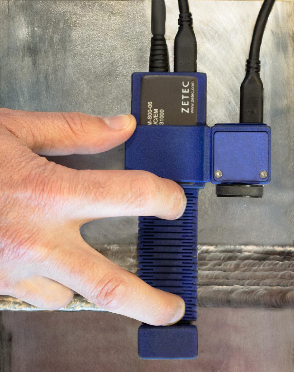
Figure 3. Surf-X probe on weld.
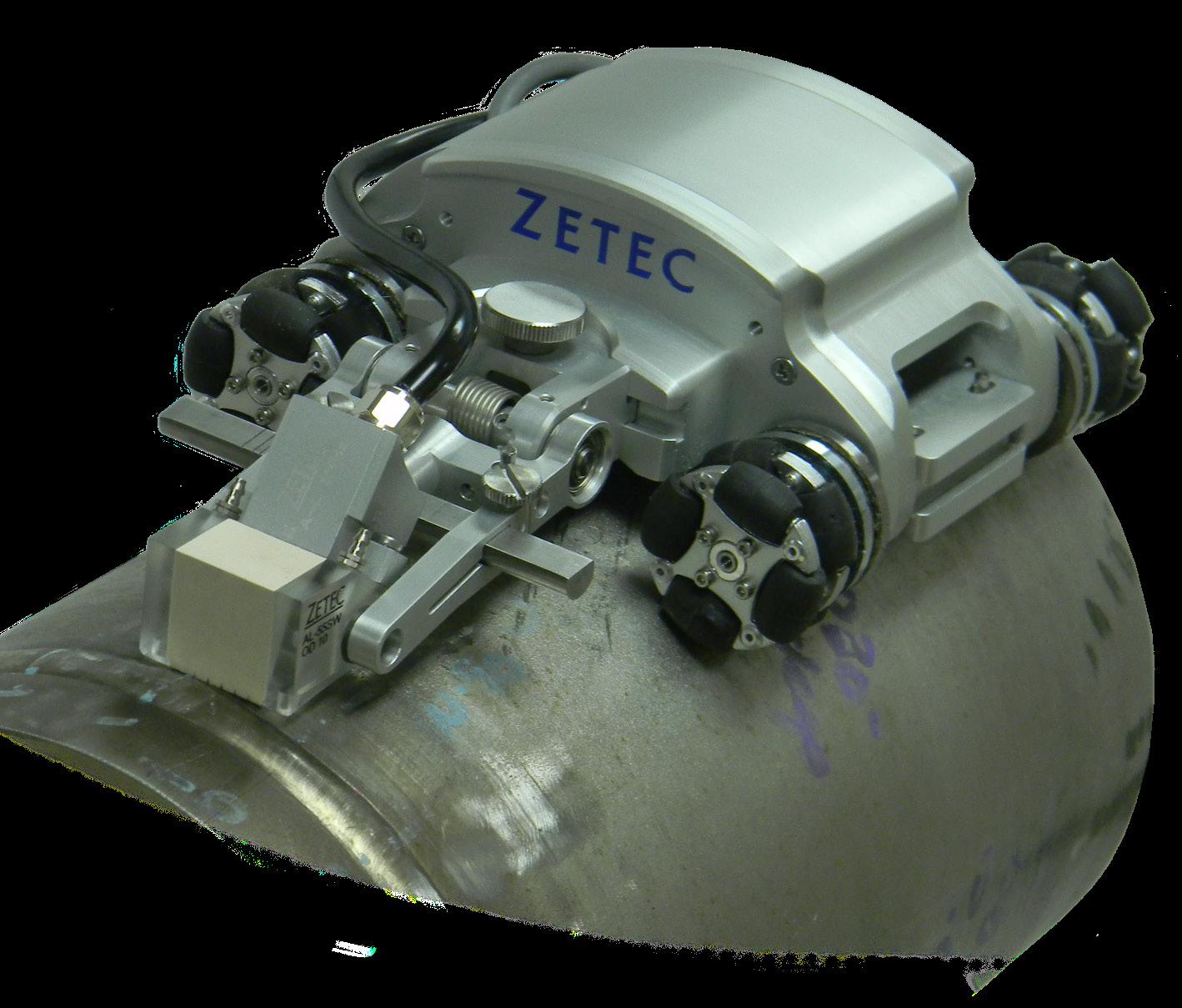
Figure 4. NDT sweeper pipe.