8 minute read
A view from the inside


end uses the percussive force to pull out the pipe segments, with additional equipment providing pulling force.
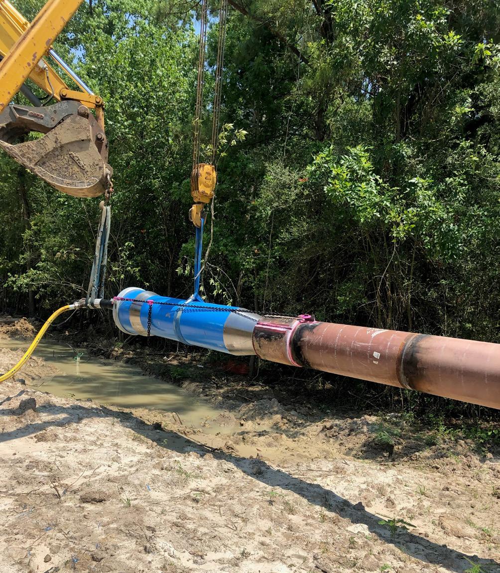
On the job: pipe extraction saves gas infrastructure project On an infrastructure expansion project near Houston, Texas in 2021, HDD contractor Directional Service South had to face an unexpected challenge caused by an unpleasant incident: a sizable section of recently installed gas transmission main had been damaged during the installation by underground obstacles, and now had to be removed and replaced. Jake Gautreaux, Founder and Co-owner of Directional Service South, explains: “For this project, we were tasked with installing several miles of 500 mm steel gas transmission main with installation lengths ranging from 150 to 920 m and ScarGuard®-coated pipe welds. The whole project covered 30 HDD crossings. After one particular 360 m long installation, crews noticed an issue with some damage to the pipe. It was going to need to be replaced.”
According to TT Technologies’ Rick Melvin, pipe extraction is an evolution of existing ramming techniques developed over time. “The extraction process is really an extension of several HDD Assist methods we developed over the years using the pneumatic pipe rammer”, he says. “The things we’ve learned from salvaging stuck bores and retrieving drill stems with the help of pipe rammers have enabled full scale pipe extraction to become a reality.” The project in Houston would put that knowledge to the test.
Melvin states that, for a full pipe extraction, it’s about using the right balance of force: “In this case you need pulling force, which can be an excavator or directional drill, combined with the percussive force of the pipe rammer. Now, these forces can be combined and applied in different ways depending on the specific jobsite situation. That’s where the complexity of the process lies. How to balance and apply the forces in a way to remove the pipe from the ground.”
The rammer’s percussive force gets the pipe moving Back to Houston; regarding the area in question, the whole installation turned out trickier than expected. “We installed the crossing without trouble but couldn’t tie it in right away”, tells Gautreaux. “We had to spin around and install the next crossing, drilling the other way. So, we were basically sitting on top of the one we just put in. Only after we had installed that next pipe section, we were able to access that first pipe.” That’s when they noticed the damage – a large scratch ran across the whole visible pipe length and breached the coating. “A quick decision regarding the future of that section had to be taken.”
The full extent of the damage could not be considered, as a section lay underground. In agreement with the project owner, it was therefore determined that the pipe was to be removed and replaced. The new pipe would furthermore be completely wrapped in ScarGuard® to help prevent any possible damage.
When the extraction works began, the pipe had already been in the ground for two months. “The wrapping on the welds is abrasive and creates friction, which made pulling the pipe out extremely difficult”, tells Gautreaux. Initial attempts to use static pull force to remove the pipe failed. “In addition, we wanted to pull in the 360 m replacement section of pipe at the same time. That’s when we brought in the GRUNDORAM Taurus rammer to complete the extraction configuration.”
The pipe ramming tool was added to the back of the pipe string, completing a rather well-constructed extraction set-up. Melvin: “What we have during extraction is pull force on the front end of the pipe and percussive force on its back end.” The crews used a 150 t, 6 part block system to channel the static pull force from a crawler track unit, doing the pulling, to the lead end of the pipe. The percussive force of the pipe rammer, in this case, was used to re-activate the drilling fluid already surrounding the pipe in the bore hole and get the pipe moving. So, the static force can be used to extract it. “You can’t pump any more bentonite”, he says. “So, you have to use what’s already down there.”
After 10 minutes of ramming and pulling, the pipe finally started moving. Overall, it took two 12 hr days to remove the pipe and pull in the replacement simultaneously. The crews were able to extract the 360 m pipe in two 180 m sections. “The hammer worked great in breaking the line free, allowing equipment to continue movement”, says Gautreaux. “That’s the reason we bought the rammer, to have it in our fleet and on the jobsite. Time is of the essence when problems arise.”
Figure 6. HDD Assist techniques with pneumatic pipe rammers have helped directional drilling projects with everything from assisting with difficult pullbacks and recovering drill stems to salvaging bore pipe and pipe extraction.
Andrew Wilde, Principal Engineer, ROSEN UK, talks monitoring subsea pipelines using internal inspection technologies.
s the number of subsea pipelines continues to increase and both the internal and external environments that they are subjected to become more severe – deeper waters, higher operating temperatures – the requirement to monitor them for unexpected movement is an increasingly critical aspect of subsea pipeline integrity management.
Subsea pipelines are often designed to withstand movement up to a certain magnitude caused by factors such as thermal expansion or challenging metocean conditions. However, excursions from intended operating limits, extreme environmental conditions, or accidental damage through external force can all result in pipeline movement that exceeds any design limits and therefore requires some form of intervention, be it further assessment, more frequent inspection, or repair.
It is a regulatory requirement in many countries to regularly monitor subsea pipelines for signs of external damage or movement so that any issues can be identified early and addressed before an ultimate limit state is reached and potentially catastrophic failure occurs.
This article will discuss the common causes of movement in subsea pipelines, how a pipeline operator may identify, measure and monitor outof-straightness and what actions may be required upon the discovery of movement outside of design limits.

Out-of-straightness in subsea pipelines Out-of-straightness in a subsea pipeline may be part of the original design and therefore does not pose a threat to pipeline integrity. The following are examples of out-of-straightness that have their origins in the design and installation stages: ) Directional changes due to pipeline routing and installation conditions.
) Seabed topography and features (e.g. potholes, boulders and coral outcrops).
) Gravity pull where a pipeline lacks support (e.g. freespans and catenary risers).
) Crossings of existing infrastructure (e.g. pipelines and cables).
) Crossings of buckle trigger structures.
) Tie-in to pipeline inline or end termination structures.
) Crookedness of the pipejoints as per fabrication.
Many of the above upfront expected out-of-straightness situations introduce static, and in some cases dynamic, loads to a pipeline that need to be compared to stress or strain-based limits, as well as other limit states such as fatigue. Providing the pipeline is operated within its design limits, these loads should not impact the integrity of a pipeline during its design life, but may require further consideration if the life of the pipeline needs to be extended.
However, other sources of out-of-straightness may be unexpected and associated with pipe movements due to operational or environmental loadings or external impact. Examples include: ) On-bottom instability in inclement metocean conditions (e.g. severe currents during storms).
) Soil movement (e.g. by soil transportation, scour, slope instabilities and seismic activities).
) Impact by trawl boards, anchors and icebergs.
) Lateral or upheaval buckles caused by thermal expansion.
) Pipe walking (also referred to as pipe ratcheting) due to cyclic pressure and temperature loading, and gravitational pull or axial tension from, for example, catenary risers.
As pipeline movement during operation is a known phenomenon, pipeline integrity management programmes should include measures for identifying, measuring and monitoring pipeline out-of-straightness where such a threat exists.
Methods for identifying, measuring and monitoring out-of-straightness Where the operating environment of a pipeline indicates that movement is a credible threat, the integrity management plan should set out a range of mitigation measures. Key to any effective movement monitoring plan is a baseline route profile that is established immediately following installation which can be used as a reference for future inspections. The accuracy and resolution of this baseline survey should be sufficient to allow subcritical levels of pipeline movement to be differentiated from measurement errors that result in apparent change in pipeline position indicated by future surveys.
After pipeline installation, the offshore pipeline trajectory is traditionally recorded through inspections by ROVs, towed sensors, and more recently also by AUVs. These inspections may involve a myriad of tools such as cameras, single beam, multi beam, and side scan sonar systems or sub-bottom profiling with high resolution multi-channel/multi-component seismic, magnetometers and gradiometers.
No single tool is perfect when it comes to measuring pipeline out-of-straightness, and increasingly operators are using a combination of methods in a complimentary manner. All methods have their particular advantages and limitations. The main challenges with ROVs are that they are time consuming inspections to perform, and costly because they require a sizable support vessel and skilled operators. Challenging environmental conditions can also limit their successful application and limit the quality of data that is gathered. A cost-effective alternative that overcomes these limitations, and has the prospect of providing superior measurements, involves the use of inertial measurement units (IMU) mounted to inline inspection (ILI) tools. Since the IMU will run internally within the pipeline, it is capable of recording the out-ofstraightness throughout the full length of the pipeline from launcher to receiver, and its accuracy is not affected by environmental conditions, e.g. poor visibility.
ILI is a fundamental aspect of most pipeline integrity management programmes and for subsea lines these systems are most commonly used to detect, size and monitor corrosion activity within the pipeline. IMUs can be mounted to those inspection tools, to cleaning pigs and, unless more frequent inspections are desired, do not require a dedicated inspection run.
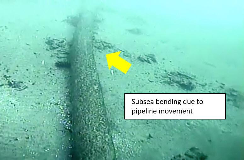
Figure 1. Pipeline out-of-straightness caused by external impact. (Photo courtesy of US Coast Guard)


