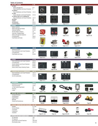
Table of Contents 360 PANEL SYSTEM
DC MAIN
4–23
Battery Management 5–8 Power Distribution and Circuit Protection 9 DC BRANCH
Power Distribution and Circuit Protection 10–13 AC MAIN
Source Selection and Circuit Protection
14–15
Pages 5–9
Pages 10–13
Pages 14–15
Pages 16–17
Page 18
Page 19
Pages 20–21
Pages 22–23
Pages 25–28
Pages 29–30
Pages 31–32
Page 33
Pages 34–36
Page 37
Pages 38–43
Pages 44–47
Pages 44–47
Pages 49–51
Pages 52–53
Page 54
Pages 55–56
Page 56
Pages 58–59
Pages 60–63
Pages 64–65
Pages 66–68
Pages 66–68
Pages 70–71
Pages 72–73
Pages 74–75
Pages 77–78
Pages 79–81
Page 80
Page 82
Pages 83–87
Page 89
Pages 90–91
Pages 92–93
Page 94
Page 95
Pages 97–100
Page 101
Pages 102–104
Page 105
Page 105
AC BRANCH AND AC/DC COMBINATION
Power Distribution and Circuit Protection 16–17 METERING 18 GAUGES 19 ACCESSORIES 20-21 CUSTOM PANELS 22-23 DC MAIN 24–47 Battery Switches 25–28 Battery Management Panels 29–30 Solenoid Switches 31–32 Remote Battery Switches 33 Automatic Charging Relays 34-36 Battery Management Solutions 37 Circuit Breakers 38-43 Fuse Blocks and Fuses 44-47
DC BRANCH Waterproof Panels Power Distribution and Circuit Protection Circuit Breakers Fuse Blocks and Fuses
48–56 49–51 52–53 54 55–56
AC MAIN Power Distribution and Circuit Protection Circuit Breakers Source Selection and Circuit Protection Rotary Switches Rotary Switch Source Selection Panels
57–68 58–59 60–63 64–65 66-68 66–68
AC BRANCH AND AC/DC COMBINATION Power Distribution and Circuit Protection Circuit Breakers AC/DC Combination
69–75 70–71 72–73 74–75
ACCESSORIES Waterproof Accessories Panel Accessories 12 Volt Socket-Plug System Dimmers Labels
76–87 77–78 79–81 80 82 83–87
METERING AND ACCESSORIES Analog DIN Meters Analog Meters Digital Meters Metering Shunts and Transformers
88–95 89 90–91 92–93 94 95
BUSBARS, CONNECTORS AND INSULATORS BusBars Terminal Blocks Connectors CableClams Insulators
96–105 97–100 101 102–104 105 105
APPENDIX AND PART NUMBER INDEX DC Appendix AC Appendix Quick Guide to Circuit Protection Part Number Index
106–112 106 107 108–109 110–112
1
How to Use This Catalog The following icons are shown throughout this catalog to indicate features that are specific to a model:
• Amperage Cranking Rating (10 Seconds) • Ampérage au lancement (10 secondes) • Amperaje de potencia de rotación (10 segundos) • Amperaggio alla rotazione del motorino di avviamento (10 secondi)
I 3
• Amperage Intermittent Rating (3 Seconds) • Ampérage intermittent (3 secondes) • Amperaje de potencia intermitente (3 segundos) • Amperaggio intermittente (3 secondi)
I 300
• Amperage Intermittent Rating (5 Minutes) • Ampérage intermittent (5 min.) • Amperaje de potencia intermitente (5 min.) • Amperaggio intermittente (5 min)
I ic
• Amperage Interrupting Capacity • Ampérage pouvoir de coupure • Amperaje potencia de interrupción • Amperaggio capacità di apertura
I mxo
• Amperage Maximum Operating • Ampérage maximum de fonctionnement • Amperaje máximo de funcionamiento • Amperaggio al funzionamento a pieno carico
I oc
• Amperage Operating Current • Courant de fonctionnement en ampères • Corriente operativa de amperaje • Amperaggio corrente operativ
I tr
• Amperage Trip Reference • Référence de déclenchement en ampères • Referencia de disparo de amperaje • Riferimento di attivazione amperaggio
C s
• Switching Cycles • Périodicité de démarrage • Ciclos de conmutación • Cicli di commutazione
• Analog Ammeter • Ampèremètre analogique • Amperímetro analógico • Amperometro analogico
• Analog Voltmeter • Voltmètre analogique • Voltímetro analógico • Amperometro analogico
• Analog DIN Voltmeter • Voltmètre DIN analogique • Voltímetro DIN analógico • Voltmetro analogico DIN
• Digital Multimeter • Multimètre numérique • Multímetro digital • Multimetro digitale
• IP66—withstands water from heavy seas • IP66—résiste à l’eau par grosse mer • IP66—es resistente al agua de la mar gruesa • IP66—resistente all’acqua del mare
• Meets ignition protection requirements • Répond aux exigences de protection contre l’inflammation • Cumple con los requisitos de protección del encendido • Conforme ai requisiti di protezione contro l’innesco
E • CE marked
• Marqué CE • Marcado CE • Marchi CE
• Tin-plated copper (250% more conductive than brass) • Cuivre étamé (250% plus conducteur que le laiton) • Cobre hojalatado (250% más conductivo que el latón) • Rame stagnato (250% più conduttivo dell’ottone)
I 10
• IP67—temporary immersion for 30 minutes • IP67—Immersion temporaire pendant 30 minutes • IP67—inmersión temporal de 30 minutos • IP67—resistente ad immersioni temporanee per 30 minuti
• Amperage Continuous Rating • Ampérage continu • Amperaje continuo • Amperaggio continuo
• 24-hour circuits • Circuits 24 heures • Circuitos de 24 horas • Circuiti 24 h
Regulatory icons are shown under the Regulatory heading:
The following Rating Symbols are shown throughout this catalog:
I c
The camera icon is shown in the tables to indicate the products that are pictured:
• Pictured products • Produits illustrés • Imágenes de los productos • Prodotti raffigurati
New and updated products are indicated by the following: New
• New products • Nouveaux produits • Productos nuevos • Nuovi prodotti
UPDATED • Updated products • Produits mis à jour • Productos actualizados • Prodotti aggiornati
Tmxo • Temperature Maximum Operating
• Température maximum de fonctionnement • Temperatura máxima en funcionamiento • Temperatura massima di esercizio
Tmno • Temperature Minimum Operating
• Température minimum de fonctionnement • Temperatura mínima en funcionamiento • Temperatura minima di esercizio
Vmxo • Voltage Maximum Operating
• Tension maximum de fonctionnement • Voltaje máximo en funcionamiento • Tensione massima di esercizio
Vmno • Voltage Minimum Operating
• Tension minimum de fonctionnement • Voltaje mínimo de funcionamiento • Tensione minima di esercizio
• 24-hour circuits are “ON” all of the time Circuits 24 heures allumés en permanence Los circuitos de 24 horas están siempre “ENCEDIDOS” I circuiti 24 h sono costantemente inseriti
• 24-hour circuits are connected directly to a battery bank Circuits 24 heures branchés directement à un groupe de batteries Los circuitos de 24 horas están directamente conectados a un conjunto de baterías I circuiti 24 h sono direttamente collegati ad un gruppo di batterie
• 24-hour circuits are centrally located and labeled Circuits 24 heures en position centrale et étiquetés Los circuitos de 24 horas se encuentran en una zona céntrica y están etiquetados I circuiti 24 h sono alloggiati centralmente ed etichettati
2
New Products Battery Management Panels
Remote Control Panels
Simultaneously switches two isolated battery banks
Provides switching of up to three ML-Series Remote Battery Switches or ML-Series Automatic Charging Relays
360 PANEL SYSTEM—page 5, 7
1141
—185-Series —Medium Duty Push Button Reset-Only
—with backlighting Provides circuit protection and switching in a compact and economical panel
Provides a method of mounting medium to high-amperage thermal circuit breakers 360 PANEL SYSTEM—page 9
1477
C-Series 240 Volt AC Circuit Breaker Panels
360 PANEL SYSTEM—pages 10–11
Provides a method of mounting DIN Rail circuit breakers
360 PANEL SYSTEM—page 15
1168
e -Series and HD-Series Battery Switches
360 PANEL SYSTEM—page 15
—with manual control
Switches battery banks to all loads (No Combine Function)
Automatically manages the charging of two large battery banks 11001
DC MAIN—page 36
ML-Series Remote Control Contura Switches
Push Button Reset-Only Circuit Breakers—with screw terminals
Provides remote management of multiple battery bank switching and ACR control from a convenient location
Provides economical circuit protection when switching is provided elsewhere
2145
DC MAIN—page 38
Medium Duty Push Button Reset-Only Circuit Breakers
Terminal Fuse Block (MRBF)
Provides medium duty circuit protection when switching is provided elsewhere
Easily and economically satisfies the ABYC 7" circuit protection rule for circuit protection up to 300 Amps 2142
2132
DC MAIN—page 44
2151
WeatherDeck™ Waterproof Circuit Breaker Panels—8 position
New, low cost design meets a wide range of fusing requirements for high-amperage loads
Provides push-to-reset circuit protection for open-cockpit and flybridge applications
5503
DC BRANCH—page 49
4378
Seamless Copper Lugs, Splices, and Crimp Tool
PowerBar Common BusBar Provides compact highampere busing with 3/8" terminal studs
CONNECTORS—page 100
7623
—double terminal
ANL and Class T Fuse Blocks
DC MAIN—page 46, 47
1174
ML-Series Heavy Duty Automatic Charging Relays (Magnetic Latching)
—Selector (3 Position)
DC MAIN—page 39
1151
RCBO Mounting Panels
Provides both source selection and circuit protection for boats with 240V AC systems
DC MAIN—page 37
1147
Push Button Reset-Only Circuit Breaker and Rocker Switch Panels
Thermal Circuit Breaker Mounting Panels
DC MAIN—page 27–28
360 PANEL SYSTEM—page 8
—Heavy Duty and Professional Duty Meets the demanding requirements of marine, industrial, and heavy-duty truck environments 2019
CONNECTORS—page 102
Specifications subject to change. See www.bluesea.com for current information.
2290
3
360 Panel System In response to customer requests for a more versatile panel, Blue Sea Systems has developed the 360 Panel System. This unique approach to panels offers significant advantages over traditional flat aluminum panels— flexibility, broadest range of functionality, and advanced design features. This panel system meets both the visual and functional demands of the most discerning boaters.
360 Panel System Table of Contents
4
DC MAIN
DC BRANCH
AC MAIN
• Battery Management (pages 5–8) • Power Distribution and Circuit Protection (page 9)
• Power Distribution and Circuit Protection (pages 10–13)
• Source Selection (pages 14–15) • Power Distribution and Circuit Protection (page 16)
AC BRANCH AND AC/DC
METERING, GAUGES, AND ACCESSORIES
CUSTOM
• Power Distribution and Circuit Protection (pages 16–17)
• Metering (page 18) • Gauges (page 19) • Accessories (pages 20–21)
• Custom Panels (pages 22–23)
Specifications subject to change. See www.bluesea.com for current information.
Battery Management Single Battery Bank Management Panels
360 Panel System | DC Main
ON–OFF Battery Switch combined with DC distribution provides control of key functions Component References • ON–OFF Battery Switch 6006200* (page 26) • A-Series Flat Rocker Circuit Breakers (page 54) • C-Series Flat Rocker Circuit Breakers (page 43) • Push Button Reset-Only Circuit Breakers (page 38) • ON–OFF (SPST) Rocker Switches (page 20) • Square Format Label Set 4218 included* (pages 84–85)
Model Specific Features (see table below) Backlit label positions “ON” indicating LEDs installed in all circuit positions 24-hour circuits
Panel Specifications
Vmxo Voltage Maximum Operating Itr Amperage Trip Reference
See table below See table below
Battery Switch Specifications
I10 I300 Ic
Cranking Rating: 10 sec. Intermittent Rating: 5 min. Continuous Rating
1,500 Amps 500 Amps 300 Amps
1400
1139
1140
1400
1401
PN
Specific Features
DC
Vmxo
1402
Flat Rocker Circuit Breakers C-Series
A-Series
MAIN 100A (Itr)
BRANCH 15A (Itr)
Push Button Reset-Only Circuit Breakers BRANCH 10A (Itr)
BRANCH 15A (Itr)
1403 ON-OFF (SPST) Rocker Switches
Width in (mm)
Height in (mm)
Depth in (mm)
Weight lb (kg)
1139
-
-
-
-
-
-
-
4.88 (123.83) 4.75 (120.65)
0.50 (0.23)
0.50 (0.23)
1140
-
48
-
-
-
-
-
4.88 (123.83) 4.75 (120.65) 2.50 (63.50)
1.15 (0.52)
1400
24
-
-
-
8
-
4.88 (123.83) 7.75 (196.85) 3.50 (88.90) 3.20 (81.28)
1401
12
-
-
4
-
4
4.88 (123.83) 7.75 (196.85) 3.50 (88.90) 3.20 (81.28)
1402
12
1
-
-
3
-
4.88 (123.83) 7.75 (196.85) 3.50 (88.90) 3.20 (81.28)
1403
12†
1
3
-
-
-
4.88 (123.83) 7.75 (196.85) 3.25 (82.55) 3.20 (81.28)
New * Not included with 1139 | † Owner upgradable to 24 Volts DC with 4113, 12 to 24 Volt Conversion Kit (page 20)
Specifications subject to change. See www.bluesea.com for current information.
5
Battery Management 360 Panel System | DC Main
Dual Battery Bank Management Panels ON–OFF Battery Switches offer complete control of two battery banks Features • Isolates the Engine circuit from the House circuit • Allows independent battery discharge • Allows emergency cross connect between isolated battery banks • Protects electronics from sags and spikes caused by engine cranking
Component References • ON–OFF Battery Switch 6006200 (page 26) • A-Series Flat Rocker Circuit Breakers (page 54) • C-Series Flat Rocker Circuit Breakers (page 43) • Square Format Label Set 4218 included (pages 84–85)
Model Specific Features See table below Backlit label positions “ON” indicating LEDs installed in all circuit positions
Panel Specifications
Vmxo Voltage Maximum Operating Itr Amperage Trip Reference
See table below See table below
Battery Switch Specifications Cranking Rating: 10 sec. Intermittent Rating: 5 min. Continuous Rating
I10 I300 Ic
1,500 Amps 500 Amps 300 Amps
1404
1405
1405
PN
6
Specific Features
DC
Vmxo
1407 C-Series Flat Rocker Circuit Breakers MAIN 100A (Itr)
1406 A-Series Flat Rocker Circuit Breakers BRANCH 15A (Itr)
Width in (mm)
Height in (mm)
Depth in (mm)
Weight lb (kg)
1404
12*
1
3
13.63 (346.08)
4.75 (120.65)
3.50 (88.90)
5.50 (2.50)
1405
12*
1
3
4.88 (123.83)
10.75 (273.05)
3.50 (88.90)
5.30 (2.40)
1406
-
48
-
-
13.63 (346.08)
4.75 (120.65)
2.50 (63.50)
5.50 (2.50)
1407
-
48
-
-
4.88 (123.83)
10.75 (273.05)
2.50 (63.50)
5.30 (2.40)
* Owner upgradable to 24 Volts DC with 4113 - 12 to 24 Volt Conversion Kit (page 20)
Specifications subject to change. See www.bluesea.com for current information.
Battery Management Dual Battery Bank Management Panels
360 Panel System | DC Main
Dual Circuit Plus™ Battery Switch combined with DC distribution simplifies switching of two battery banks and provides control of key functions Component References
• Dual Circuit Plus™ Battery Switch 6011200* (page 26) • A-Series Flat Rocker Circuit Breakers (page 54) • C-Series Flat Rocker Circuit Breakers (page 43) • Push Button Reset-Only Circuit Breakers (page 38) • ON–OFF (SPST) Rocker Switches (page 20) • Square Format Label Set 4218 included* (pages 84–85)
Model Specific Features (see table below) Backlit label positions “ON” indicating LEDs installed in all circuit positions 24-hour circuits
Panel Specifications
Vmxo Voltage Maximum Operating Itr Amperage Trip Reference
See table below See table below
Battery Switch Specifications
I10 I300 Ic
Cranking Rating: 10 sec. Intermittent Rating: 5 min. Continuous Rating:
1,000 Amps 450 Amps 300 Amps
1411
1139
1141
1408
1410
1409
DC
1411
Push Button A-Series C-Series ON-OFF Reset-Only Flat Rocker Flat Rocker (SPST) Circuit Breakers Circuit Breakers Circuit Breakers Rocker MAIN BRANCH BRANCH BRANCH Switches 100A (Itr) 15A (Itr) 10A (Itr) 15A (Itr)
Width in (mm)
Height in (mm)
Depth in (mm)
Specific Features
Vmxo
1139
-
12
-
-
-
-
-
4.88 (123.83) 4.75 (120.65) 0.50 (12.70) 0.50 (0.23)
1141
-
32
-
-
-
-
-
4.88 (123.83) 4.75 (120.65) 2.50 (63.50) 1.30 (0.59)
1408
12
1
-
-
3
-
4.88 (123.83) 7.75 (196.85) 3.50 (88.90) 3.20 (1.45)
1409
12†
1
3
-
-
-
4.88 (123.83) 7.75 (196.85) 3.25 (82.55) 3.20 (1.45)
1410
12
-
-
4
-
4
4.88 (123.83) 7.75 (196.85) 3.50 (88.90) 3.20 (1.45)
1411
24
-
-
-
8
-
4.88 (123.83) 7.75 (196.85) 3.50 (88.90) 3.20 (1.45)
PN
Weight lb (kg)
New *
Not included with 1139 | † Owner upgradable to 24 Volts DC with 4113 - 12 to 24 Volt Conversion Kit (page 20)
Specifications subject to change. See www.bluesea.com for current information.
7
Battery Management 360 Panel System | DC Main
Triple Battery Bank Management Panel Dual Circuit Plus™ Battery Switches simplify switching of three battery banks and combine DC functions into one compact panel Features • Allows independent battery discharge • Allows emergency cross connect between isolated battery banks • 24-hour circuits • Backlit label positions • “ON” indicating LEDs installed
Component References • Dual Circuit Plus™ Battery Switches 6011200 (page 26) • A-Series Flat Rocker Circuit Breakers (page 54) • Push Button Reset-Only Circuit Breakers (page 38) • Square Format Label Set 4218 included (pages 84–85)
Panel Specifications
Vmxo Voltage Maximum Operating Itr Amperage Trip Reference
See table below See table below
Battery Switch Specifications
I10 I300 Ic
Cranking Rating: 10 sec. Intermittent Rating: 5 min. Continuous Rating
1,000 Amps 450 Amps 300 Amps
1412
PN
DC
A-Series Flat Rocker Circuit Breakers
Push Button Reset-Only Circuit Breakers
BRANCH 15A (Itr)
BRANCH 15A (Itr)
4
8
Vmxo 12*
1412
Width in (mm)
Height in (mm)
Depth in (mm)
9.25 (234.95)
7.75 (196.85)
3.50 (88.90)
Remote Control Panels Provides switching of up to three ML-Series Remote Battery Switches or ML-Series Automatic Charging Relays • Lockout slides reduce the risk of accidental switching • 1147 for use with two ML-Series Switches (pages 32—33) and one ML-Series Automatic Charging Relay (page 36) • 1148 for use with ML-Series Switches (pages 32—33) • Includes labels illustrated only • Over 500 individual labels available (pages 86—87)
Component Reference • ML-Series Remote Control Contura Switches (page 37)
Specifications
Vmxo Voltage Maximum Operating
PN 1147 1148
Included Switch PN
Vmxo
2145/2146 2145
24 24
DC
1147
See table below Function
Battery Banks 2 3
ACR 1 -
Width in (mm)
Height in (mm)
4.88 (123.83) 4.75 (120.65) 4.88 (123.83) 4.75 (120.65)
Depth in (mm)
Weight lb (kg)
2.00 (50.80) 2.00 (50.80)
1.10 (0.50) 1.10 (0.50)
New
1148
8
* Owner upgradable to 24 Volts DC with 4113, 12 to 24 Volt Conversion Kit (page 20)
Specifications subject to change. See www.bluesea.com for current information.
Weight lb (kg) 6.12 (2.78)
Power Distribution and Circuit Protection Thermal Circuit Breaker Mounting Panels
360 Panel System | DC Main
Provides an easy method for mounting medium and high amperage thermal circuit breakers Component References • Medium Duty Push Button Reset-Only Circuit Breakers (page 39) • 185-Series Circuit Breakers (page 40)
1150 (circuit breakers not included)
PN
1477 (circuit breaker not included)
Accepts Medium Duty Push Button Reset-Only Circuit Breakers
Accepts Panel Mount 185-Series Circuit Breakers
Width in (mm)
Height in (mm)
Depth in (mm)
1 2 -
1
4.88 (123.83) 4.88 (123.83) 4.88 (123.83)
4.75 (120.65) 4.75 (120.65) 4.75 (120.65)
0.50 (12.70) 0.50 (12.70) 0.50 (12.70)
1149 1150 1477
Weight lb (kg) 0.60 (0.27) 0.60 (0.27) 0.50 (0.23)
New
High-Amp C-Series Circuit Breaker Panels Provides over current protection for loads up to 300 Amperes, such as bow thrusters and anchor windlasses Features • Can function as a Main power switch • Backlit label positions • “ON” indicating LEDs installed
Component References • C-Series Flat Rocker Circuit Breakers (page 43) • Square Format Label Set 4218 included (pages 84–85)
Specifications
Vmxo Voltage Maximum Operating Itr Amperage Trip Reference
PN 1490 1491 1492 1493
Poles 1 2 2 3
DC
Vmxo 12* 12* 12* 12*
See table below See table below
1490
1491
1492
1493
C-Series Flat Rocker Circuit Breakers MAIN 50A (Itr) 1 -
MAIN 150A (Itr) 1 -
MAIN 200A (Itr) 1 -
MAIN 300A (Itr) 1
* Owner upgradable to 24 Volts DC with 4113 - 12 to 24 Volt Conversion Kit (page 20)
Specifications subject to change. See www.bluesea.com for current information.
Width in (mm) 4.88 4.88 4.88 4.88
(123.83) (123.83) (123.83) (123.83)
Height in (mm) 4.75 4.75 4.75 4.75
(120.65) (120.65) (120.65) (120.65)
Depth in (mm) 3.00 3.00 3.00 3.00
(76.20) (76.20) (76.20) (76.20)
Weight lb (kg) 1.20 1.50 1.50 1.80
(0.54) (0.68) (0.68) (0.82)
9
Power Distribution and Circuit Protection 360 Panel System | DC Branch
Push Button Reset-Only Branch Circuit Breaker Panels Provides an economical solution for 24-hour circuit protection or circuits that are switched elsewhere Features
Component References
Specifications
• Backlit label positions • 24-hour circuits
• Push Button Reset-Only Circuit Breakers (page 38) • Square Format Label Set 4205 included (pages 84–85)
Vmxo Voltage Maximum Operating
Itr
Amperage Trip Reference
See table below See table below
1451
1450
1452
1454
PN
DC
Vmxo
1450 1451 1452 1453 1454
24 24 24 24 24
Push Button Reset-Only Circuit Breakers BRANCH 15A (Itr) 8 16 16 24 24
1453
Width in (mm)
Height in (mm)
Depth in (mm)
Weight lb (kg)
4.88 (123.83) 9.25 (234.95) 4.88 (123.83) 13.63 (346.08) 4.88 (123.83)
4.75 (120.65) 4.75 (120.65) 7.75 (196.85) 4.75 (120.65) 10.75 (273.05)
3.50 (88.90) 3.50 (88.90) 3.50 (88.90) 3.50 (88.90) 3.50 (88.90)
1.30 (0.60) 3.50 (1.60) 2.50 (1.13) 4.50 (2.04) 4.20 (1.91)
Push Button Reset-Only Branch Circuit Breaker and Rocker Switch Panels Provides circuit protection and switching in a compact and economical panel Features
Component References
Model Specific Features (see table to right)
• Panels with meters include a toggle switch to • ON–OFF (SPST) Rocker Switches (page 20) monitor voltage on up to three battery banks • Square Format Label Set 4205 included (pages 84–85) • Available with or without label backlighting • Push Button Reset-Only Circuit Breakers (page 38)
Specifications
Vmxo Voltage Maximum Operating Itr Amperage Trip Reference
1151*/1455
See table to right See table to right
1152*/1460
1153/1462*
1154*/1456
1155*/1459
10
1156*/1457
* Circuit label positions are backlit
Specifications subject to change. See www.bluesea.com for current information.
1157*/1468
Analog Voltmeter (page 90) Analog Ammeter (page 90) Backlit label positions—select models only Circuit labels are not backlit (page 20)
Power Distribution and Circuit Protection 360 Panel System | DC Branch
1158*/1458
1159*/1464
1161*/1469
1162*/1470
1165*/1461
1164*/1463 PN*
1160*/1466
PN
1166*/1471
Specific Features METERS DC Function/PN
1151* 1455
-
1158* 1458
8–16V/8003
1155* 1459
8–16V/8003
1163*/1465
DC
Vmxo
1167*/1467
Push Button Circuit Breakers BRANCH 10A (Itr)
ON-OFF (SPST) Rocker Switches
Width in (mm)
Height in (mm)
Depth in (mm)
Weight lb (kg)
12
4
4
4.88 (123.83)
4.75 (120.65)
3.50 (88.90)
1.20 (0.54)
12
4
4
9.25 (234.95)
4.75 (120.65)
3.50 (88.90)
2.90 (1.32)
12
4
4
4.88 (123.83)
7.75 (196.85)
3.50 (88.90)
2.40 (1.09)
1154* 1456
-
12
8
8
9.25 (234.95)
4.75 (120.65)
3.50 (88.90)
3.00 (1.36)
1156* 1457
-
12
8
8
4.88 (123.83)
7.75 (196.85)
3.50 (88.90)
2.40 (1.09)
13.63 (346.08)
4.75 (120.65)
3.50 (88.90)
3.60 (1.63)
4.88 (123.83) 10.75 (273.05)
3.50 (88.90)
3.30 (1.50)
4.75 (120.65)
3.50 (88.90)
3.90 (1.77) 3.50 (1.59)
1153* 1462
8–16V/8003
12
8
8
1164* 1463
8–16V/8003
12
8
8
-
12
12
12
-
12
12
12
4.88 (123.83) 10.75 (273.05)
3.50 (88.90)
12
12
12
9.25 (234.95)
7.75 (196.85)
3.50 (88.90)
4.40 (2.00)
12
16
16
9.25 (234.95)
7.75 (196.85)
3.50 (88.90)
4.50 (2.04)
13.63 (346.08)
7.75 (196.85)
3.50 (88.90)
5.70 (2.59)
9.25 (234.95) 10.75 (273.05)
3.50 (88.90)
5.30 (2.40)
7.75 (196.85)
3.50 (88.90)
5.80 (2.63)
9.25 (234.95) 10.75 (273.05)
3.50 (88.90)
5.70 (2.59)
7.75 (196.85)
3.50 (88.90)
6.00 (2.72)
9.25 (234.95) 10.75 (273.05)
3.50 (88.90)
5.70 (2.59)
1152* 1460 1165* 1461 1159* 1464
8–16V/8003
1163* 1465
-
1160* 1466
8–16V/8003
0–50A/8022
12
16
16
1167* 1467
8–16V/8003
0–50A/8022
12
16
16
1162* 1470
8–16V/8003
12
20
20
1166* 1471
8–16V/8003
12
20
20
1157* 1468
-
12
24
24
1161* 1469
-
12
24
24
13.63 (346.08)
13.63 (346.08) 13.63 (346.08)
New * Circuit label positions are backlit
Specifications subject to change. See www.bluesea.com for current information.
11
Power Distribution and Circuit Protection 360 Panel System | DC Branch
12 Volt Main and Branch Circuit Breaker Panels Toggle or rocker circuit breakers provide DC Branch circuit protection and switching Features
Component References
• “ON” indicating LEDs installed in all circuit positions • Backlit label positions • Panels with meters include toggle switch to monitor voltage on up to three battery banks • Available with Flat Rocker or Black Toggle Circuit Breakers • Owner upgradable to 24 Volts DC with 4113 - 12 to 24 Volt Conversion Kit (page 20)
• A-Series Flat Rocker and Black Toggle Circuit Breakers (page 54) • C-Series Flat Rocker Circuit Breakers (page 43) • Square Format Label Set 4205 included (pages 84–85) Analog Voltmeter and Analog Ammeter (pages 90–91) Digital Multimeter (pages 92–93)
Specifications
Vmxo Voltage Maximum Operating Itr Amperage Trip Reference
See table to right See table to right
1216/1116*
1200/1100*
12
Model Specific Features (see table to right)
1222/1122*
1220/1120*
1224/1124*
1201/1101*
1217/1117*
1221
* Toggle actuator model not shown
Specifications subject to change. See www.bluesea.com for current information.
1225/1125*
Power Distribution and Circuit Protection
1227/1127*
360 Panel System | DC Branch
1223/1123*
1226
1121
1126 Rocker Panel PN
Toggle Panel PN
DC
Vmxo
Specific Features
C-Series Circuit Breakers
A-Series Circuit Breakers
METERS DC Function/PN
MAIN 100A (Itr)
BRANCH 15A (Itr)
Width in (mm)
Height in (mm)
Weight lb (kg) |
Depth in (mm)
1216 1116
12
-
-
4
4.88 (123.83)
4.75 (120.65)
3.00 (76.20) 1.30 (0.59) | 1.30 (0.59)
1200 1100
12
-
-
8
4.88 (123.83)
7.75 (196.85)
3.00 (76.20) 2.70 (1.22) | 2.40 (1.09)
1225 1125
12
1224 1124
12†
8–16V/8003
-
1227 1127
12
Digital Multimeter/8248
1223 1123
12
1217 1117
12
Digital Multimeter/8248
-
8
9.25 (234.95)
4.75 (120.65)
3.00 (76.20) 3.76 (1.71) | 3.76 (1.71)
-
8
9.25 (234.95)
7.75 (196.85)
3.00 (76.20) 6.12 (2.78) | 5.70 (2.59)
-
8
4.88 (123.83) 10.75 (273.05) 4.00 (101.60) 4.94 (2.24) | 4.90 (2.22)
-
12
4.88 (123.83) 10.75 (273.05)
-
12
9.25 (234.95)
3.00 (76.20) 4.94 (2.24) | 5.30 (2.40)
7.75 (196.85) 4.00 (101.60) 6.12 (2.78) | 6.10 (2.77)
-
16
9.25 (234.95)
7.75 (196.85)
3.00 (76.20) 6.12 (2.78) | 6.20 (2.81)
-
16
13.63 (346.08)
7.75 (196.85)
3.00 (76.20) 7.80 (3.54) | 7.80 (3.54)
Digital Multimeter/8248
1
19
13.63 (346.08)
7.75 (196.85) 4.00 (101.60) 10.08 (4.57)|
Digital Multimeter/8248
-
20
13.63 (346.08)
7.75 (196.85) 4.00 (101.60) 7.75 (196.85)
1222 1122
12
1201 1101
12†
8–16V/8003
1221
-
12
1121
12
-
0–50A/8022
0–50A/8022
-
| 8.60 (3.90)
3.00 (76.20) 10.08 (4.57) | 8.80 (3.99)
1220 1120
12
-
24
13.63 (346.08)
1226
-
12
Digital Multimeter/8248
1
31
1126
12
Digital Multimeter/8248
-
32
13.63 (346.08) 10.75 (273.05) 4.00 (101.60) 13.62 (6.18) | | 12.00 (5.44) 13.63 (346.08) 10.75 (273.05) 4.00 (101.60) -
-
-
-
* Toggle actuator model not shown | † Owner upgradable to 24 Volts with 8240 - 18-32V DC Analog Voltmeter (page 90) in addition to 4113 - 12 to 24 Volt Conversion Kit (page 20)
Specifications subject to change. See www.bluesea.com for current information.
13
Source Selection and Circuit Protection 360 Panel System | AC Main
Rotary Switch Source Selection Panels Provides a compact and intuitive solution for safely managing multiple AC sources Features
Component Reference
• Backlit label positions • Red "Reverse Polarity" LEDs installed • Green "Power Available" LEDs installed
• Rotary Switch Source Selectors (pages 66–68)
1481/1484
Vmxo Voltage Maximum Operating Imxo Amperage Maximum Operating
1486/1483/1487
Included Rotary Switch PN
Sources
1481 1483 1482
9009 9011 9010
1484 1486 1485 1487 1489 1480 1488
Panel PN
Specifications
Function
See table below See table below
1489/1480 Maximum Minimum Wire Size Wire Size (AWG) (AWG)
1482/1485/1488
AC
AC
Poles
Vmxo
Imxo
2 2 3
2 2 2
120 120 120
30 65 30
10 6 10
14 12 14
4.88 (123.83) 4.75 (120.65) 4.88 (123.83) 4.75 (120.65) 4.88 (123.83) 4.75 (120.65)
1.91 (48.51) 2.41 (61.21) 2.41 (61.21)
1.20 (0.54) 3.50 (1.59) 1.20 (0.54)
9009 9011 9010
2 2 3
2 2 2
230† 230† 230†
30 65 30
10 6 10
14 12 14
4.88 (123.83) 4.75 (120.65) 4.88 (123.83) 4.75 (120.65) 4.88 (123.83) 4.75 (120.65)
1.91 (48.51) 2.41 (61.21) 2.41 (61.21)
1.20 (0.54) 3.50 (1.59) 1.20 (0.54)
9019 6337 9093 9077
2 2 2 3
3 4 4 3
240 240 240 240
65 30 65 65
6 10 6 6
12 14 12 12
4.88 4.88 4.88 4.88
Width in (mm)
(123.83) (123.83) (123.83) (123.83)
Height in (mm)
4.75 4.75 4.75 4.75
Depth in (mm)
Panel Weight lb (kg)
(120.65) 3.65 (92.71) (120.65) 2.98 (75.69) (120.65) 4.50 (114.30) (120.65) 5.50 (139.70)
3.50 1.20 3.50 3.50
(1.59) (0.54) (1.59) (1.59)
A-Series Circuit Breaker Source Selection Panels Provides both source selection and circuit protection for multiple AC sources Features
Component References
• Backlit label positions • Red "Reverse Polarity" LEDs installed • Green "Power Available" LEDs installed • Lockout slides prevent connecting multiple AC sources simultaneously
• A-Series Black Toggle Circuit Breakers (page 60) • A-Series Raised Rocker Circuit Breakers (page 61) • Square Format Label Set 4206 included (pages 84–85)
Specifications
Vmxo Voltage Maximum Operating Itr Amperage Trip Reference
1208/1231
14
1209†/1232†
1131/1108
Rocker Panel PN
Toggle Panel PN
1208 1231
1108 1131
1209 1232
1109 1132
A-Series Circuit Breakers
AC
See table below See table below
1132†/1109†
MAIN 30A (Itr) 2 -
MAIN 32A (Itr) -
MAIN 50A (Itr) 2
Width in (mm)
Height in (mm)
Depth in (mm)
120 120
MAIN 16A (Itr) -
4.88 (123.83) 4.88 (123.83)
4.75 (120.65) 4.75 (120.65)
3.00 (76.20) 3.00 (76.20)
230† 230†
2 -
-
2
-
4.88 (123.83) 4.88 (123.83)
4.75 (120.65) 4.75 (120.65)
3.00 (76.20) 3.00 (76.20)
Vmxo
† 230 Volt (typical of Europe)
Specifications subject to change. See www.bluesea.com for current information.
Weight lb (kg) | 1.30 (0.59) | 1.30 1.30 (0.59) | 1.30 1.30 (0.59) | 1.30 1.30 (0.59) | 1.30
(0.59) (0.59) (0.59) (0.59)
Source Selection and Circuit Protection C-Series 240 Volt AC Circuit Breaker Panels
360 Panel System | AC Main
Provides both source selection and circuit protection for boats with 240 Volt AC systems Features • Flexible 360 Panel System configuration provides spare rocker apertures which may be used for single-pole 120 Volt AC or double-pole 240 Volt AC Branch circuits • Source Selection Panels include lockout slides to prevent connecting two AC sources simultaneously
Component References • C-Series Raised Rocker Circuit Breakers—triple-pole (page 63) • C-Series Flat Rocker Circuit Breakers—triple-pole (page 43) • Square Format Label Set 4206 included (pages 84–85)
Model Specific Features (see table below) Analog DIN Voltmeter (page 89) Digital Multimeter (page 93)
Specifications
Vmxo Voltage Maximum Operating Itr Amperage Trip Reference
See table below See table below
1168 PN
Description
Specific Features
AC
Vmxo
1169
C-Series C-Series Flat Rocker Raised Rocker Circuit Breakers Circuit Breakers MAIN 50A (Itr) MAIN 50A (Itr)
METERS AC Function/PN
1172 Width in (mm)
Height in (mm)
Depth in (mm)
Weight lb (kg)
1168
Main
240
1
-
4.88 (123.83)
4.75 (120.65)
3.00 (76.20)
1.80 (0.82)
1169
Main
240
0–250V/1057
1
-
4.88 (123.83) 13.75 (349.25)
3.00 (76.20)
4.90 (2.22)
1170
Main
240
Digital Multimeter/8247
1
-
4.88 (123.83) 13.75 (349.25) 4.00 (101.60)
5.35 (2.43)
-
1171 Source Selection 240
0–250V/1057
2
4.88 (123.83) 13.75 (349.25)
3.00 (76.20)
7.20 (3.26)
1172 Source Selection 240
Digital Multimeter/8247
2
4.88 (123.83) 13.75 (349.25) 4.00 (101.60)
7.65 (3.47)
Residual Current Circuit Breaker (RCBO) Panels Reduces the risk of fire and shock hazards caused by defects in boat appliances and circuit wiring Features
• Backlit label positions* • “ON” indicating LED*
1173† (circuit breaker not included) DIN Rail Apertures
Poles
1173 1174
1 2
-
1500 1502
-
1 2
PN
Component References
Specifications
• Residual Current Circuit Breakers* (page 63)
Vmxo Voltage Maximum Operating Itr Amperage Trip Reference
1174† (circuit breaker not included) GFCI
ELCI
-
BRANCH 15A (Itr) -
MAIN 30A (Itr) -
120 120
1 -
1
AC
Vmxo
1500
See table below See table below
1502
Leakage Trip Amperage
Width in (mm)
Height in (mm)
Depth in (mm)
Weight lb (kg)
-
4.88 (123.83) 4.88 (123.83)
4.75 (120.65) 4.75 (120.65)
0.50 (12.70) 0.50 (12.70)
0.70 (0.32) 0.70 (0.32)
5mA 30mA
4.88 (123.83) 4.88 (123.83)
4.75 (120.65) 4.75 (120.65)
3.02 (76.71) 3.02 (76.71)
0.93 (0.42) 1.10 (0.50)
New * Not included with 1173 or 1174 | † DIN Rail mounting bracket included
Specifications subject to change. See www.bluesea.com for current information.
15
Power Distribution and Circuit Protection 360 Panel System | AC Branch
A-Series Main and Branch Circuit Breaker Panels Toggle or rocker circuit breakers provide AC Main or AC Branch circuit protection and switching Features
Component References
• Backlit label positions • “ON” indicating LEDs installed in all circuit positions • Panels with AC Main include “REVERSE POLARITY” LED
• A-Series Black Toggle Circuit Breakers (pages 60, 72) • A-Series Flat Rocker Circuit Breakers (pages 61, 73) • Square Format Label Set 4206 included (pages 84–85)
Model Specific Feature (see table below)
Specifications
1210/1211†
1214/1215†/1114/1115†
1230/1233†
1228/1229†
1202/1203†/1102/1103†
1206/1207†/1106/1107†
1110/1111†
1130/1133† Specific Feature METERS Function
Toggle Rocker Panel PN Panel PN
16
Vmxo Voltage Maximum Operating Itr Amperage Trip Reference
Analog Voltmeter (page 91)
A-Series Circuit Breakers
AC
Vmxo
MAIN BRANCH BRANCH MAIN 16A (Itr) 30A (Itr) 8A (Itr) 15A (Itr)
Width in (mm)
See table below See table below
1128/1129†
Height in (mm)
Depth in (mm)
Weight lb (kg) |
4.88 (123.83) 4.75 (120.65) 3.00 (76.20) 1.30 (0.59) | 1.30 (0.59) 4.88 (123.83) 7.75 (196.85) 3.00 (76.20) 3.20 (1.45) | 2.70 (1.22)
1210
1110
-
120
-
-
-
4
1228
1128
-
120
-
-
-
8
1214
1114
-
120
-
1
-
2
4.88 (123.83) 4.75 (120.65) 3.00 (76.20) 1.30 (0.59) | 1.30 (0.59)
1206
1106
0–150V/9353 120
-
1
-
2
4.88 (123.83) 7.75 (196.85) 3.00 (76.20) 1.80 (0.82) | 3.20 (1.45)
1230
1130
-
120
-
1
-
6
1202
1102
-
120
-
1
-
6
9.25 (234.95) 4.75 (120.65) 3.00 (76.20) 3.76 (1.71) | 3.76 (1.71) 4.88 (123.83) 7.75 (196.85) 3.00 (76.20) 2.70 (1.22) | 2.40 (1.09)
1211
1111
-
230†
-
-
4
-
1229
1129
-
230†
-
-
8
-
4.88 (123.83) 4.75 (120.65) 3.00 (76.20) 1.30 (0.59) | 1.30 (0.59) 4.88 (123.83) 7.75 (196.85) 3.00 (76.20) 3.20 (1.45) | 2.70 (1.22)
1215
1115
-
1207
1107
1233
1133
1203
1103
230†
1
-
2
-
4.88 (123.83) 4.75 (120.65) 3.00 (76.20) 1.30 (0.59) | 1.30 (0.59)
0–250V/9354 230†
1
-
2
-
4.88 (123.83) 7.75 (196.85) 3.00 (76.20) 1.80 (0.82) | 3.20 (1.45)
-
230†
1
-
6
-
-
230†
1
-
6
-
9.25 (234.95) 4.75 (120.65) 3.00 (76.20) 3.85 (1.75) | 3.85 (1.75) 4.88 (123.83) 7.75 (196.85) 3.00 (76.20) 2.70 (1.22) | 3.20 (1.45)
† 230 Volt (typical of Europe)
Specifications subject to change. See www.bluesea.com for current information.
Power Distribution and Circuit Protection Combination AC/DC Circuit Breaker Panels Combines all AC and DC switching, circuit protection, source selection and monitoring into a single power distribution panel Component References
• “ON” indicating LEDs installed in all circuit positions • Backlit label positions • Panels with meters include toggle switch to monitor voltage on up to three battery banks • Available with Flat Rocker or Black Toggle Circuit Breakers • Panels with sources include lockout slides to prevent connecting multiple AC sources simultaneously • Owner upgradable to 24 Volts DC with 4113 - 12 to 24 Volt Conversion Kit (page 20)
• A-Series Black Toggle Circuit Breakers (page 60, 72) • A-Series (page 61, 63) and C-Series (page 43) Flat Rocker Circuit Breakers • Insulating Rear Covers (page 20)
360 Panel System | AC/DC
Features
Model Specific Features Analog Voltmeter and Analog Ammeter (pages 90–91) Digital Multimeter (pages 92–93)
Specifications
Vmxo Voltage Maximum Operating Itr Amperage Trip Reference
1204/1205*/1104/1105*
See table below See table below
1218/1219*/1118/1119* Specific Features / METERS Group A B C
D
E
DC Function/PN 8–16V/8003 0–100A/8017
AC Function/PN 0–150A/9353
Multimeter/8248
Multimeter/8247
8–16V/8003
0–150V/9353
0–100A/8017
0–50A/9630
8–16V/8003 0–100A/8017
0–250V/9354
8–16V/8003
0–250V/9354
0–100A/8017
0–50A/9630
1212/1213*/1112/1113* Rocker Toggle Panel Panel Meter PN PN Group
DC
AC
Vmxo Vmxo
AC Sources
AC Circuit Breakers MAIN (Itr)
DC Circuit Breakers
BRANCH (Itr) MAIN (Itr) BRANCH (Itr)
16A 30A 32A 50A 8A
Width in (mm)
Height in (mm)
Depth in (mm)
Weight lb (kg)
15A
100A
15A
1204
-
A
12 † 120
-
-
1
-
-
-
6
1
15
13.63 (346.08) 10.75 (273.05) 4.00 (101.60) 11.90 (5.40)
-
1104
A
12 † 120
-
-
1
-
-
-
6
-
16
13.63 (346.08) 10.75 (273.05) 4.00 (101.60) 11.90 (5.40)
1218
-
B
12
120
-
-
1
-
-
-
6
1
19
13.63 (346.08) 10.75 (273.05) 4.00 (101.60) 13.62 (6.18)
-
1118
B
12
120
-
-
1
-
-
-
6
-
20
13.63 (346.08) 10.75 (273.05) 4.00 (101.60) 12.20 (5.53)
1212
-
C
12 † 120
3
-
2
-
2
-
8
1
15
18.00 (457.20) 10.75 (273.05) 4.00 (101.60) 17.80 (8.07)
-
1112
C
12 † 120
3
-
2
-
2
-
8
-
16
18.00 (457.20) 10.75 (273.05) 4.00 (101.60) 17.80 (8.07)
1205
-
D
12 † 230*
-
1
-
-
-
6
-
1
15
13.63 (346.08) 10.75 (273.05) 4.00 (101.60) 11.90 (5.40)
12 † 230*
-
1105
D
-
1
-
-
-
6
-
-
16
13.63 (346.08) 10.75 (273.05) 4.00 (101.60) 11.90 (5.40)
1219
-
B
12
230*
-
1
-
-
-
6
-
1
19
13.63 (346.08) 10.75 (273.05) 4.00 (101.60) 13.62 (6.18)
-
1119
B
12
230*
-
1
-
-
-
6
-
-
20
13.63 (346.08) 10.75 (273.05) 4.00 (101.60) 12.20 (5.53)
1213
-
12 † 230*
3
2
-
2
-
8
-
1
15
18.00 (457.20) 10.75 (273.05) 4.00 (101.60) 17.80 (8.07)
-
1113
E E
12 † 230*
3
2
-
2
-
8
-
-
16
18.00 (457.20) 10.75 (273.05) 4.00 (101.60) 18.00 (8.16)
* 230 Volt (typical of Europe) | † Owner upgradable to 24 Volts DC with 8240 - 18-32V Analog Voltmeter (page 90) in addition to 4113 - 12 to 24 Volt Conversion Kit (page 20)
Specifications subject to change. See www.bluesea.com for current information.
17
Metering 360 Panel System | Metering
DC Analog Voltmeter Panel Provides monitoring of multiple battery banks • Standard 2-3 ∕4" Voltmeter (page 90) • 3 position switch to monitor voltage on up to three battery banks
Specifications
Vmxo
Voltage Maximum Operating
PN 1473
16 Volts DC
Meter Function/PN
Width in (mm)
Height in (mm)
Depth in (mm)
Weight lb (kg)
8–16V DC/8003
4.88 (123.83)
4.75 (120.65)
2.00 (50.80)
1.30 (0.59) 1473
DC Digital Voltmeter Panel Provides monitoring of multiple battery banks • Standard 2-3 ∕4" Digital Voltmeter (page 92) • 3 position switch to monitor voltage on up to three battery banks
Specifications
Vmxo
Voltage Maximum Operating
PN 1474
60 Volts DC
Meter Function/PN
Width in (mm)
Height in (mm)
Depth in (mm)
Weight lb (kg)
0–60V DC/8235
4.88 (123.83)
4.75 (120.65)
4.00 (101.60)
1.30 (0.59) 1474
Meter Mounting Panels Provides an easy method of mounting meters For a full selection of meters see pages 89–93
PN
Function
Width in (mm)
Height in (mm)
Weight lb (kg)
1475 Accepts 2-3 ∕4" Analog or Digital Meter
4.88 (123.83)
4.75 (120.65)
0.60 (15.24)
1476 Accepts two 2-3 ∕4" Analog or Digital Meters
4.88 (123.83)
7.75 (196.85)
1.05 (26.67)
1516 Accepts Analog DIN Meter
4.88 (123.83)
4.75 (120.65)
0.50 (12.70)
1517 Accepts two Analog DIN Meters
4.88 (123.83)
7.75 (196.85)
0.80 (20.32) 1475 (meter not included)
1516 (meter not included)
18
Specifications subject to change. See www.bluesea.com for current information.
1517 (meters not included)
1476 (meters not included)
Gauges 2 Inch Round Gauges NOT AVAILABLE IN RETAIL PACKAGING • Water-tight, fog-resistant, anti-scratch glass face • Edge-lit • Will fit panels up to 0.8" thickness
Specifications
Vmxo Voltage Maximum Operating Tmxo Temperature Maximum Operating Tmno Temperature Minimum Operating Ioc (with edgelight) Amperage Operating Current Ioc (without edgelight) Amperage Operating Current Gauge diameter Mounting hole diameter Back clamp nuts torque
See table below 158°F (70°C) -4°F (-20°C) 180mA <100mA 2.00" (50.80mm) 2.06" (52.40mm) 5–7 in-lb
Regulatory • E Marked
PN 1020B 1021B 1022B 1023B 1024B 1025B 1026B* 1027B 1028B 1029B 1030B
DC
Function Fuel Level E–1 ∕2–F Potable Water Level E–1 ∕2–F Engine Temp 100–250°F Oil Pressure 0–80 PSI/Bar Water Pressure 0–30 PSI/kPa Voltmeter 10–16 Volts Hour Meter—10,000 hrs Battery Condition Indicator DC Ammeter 60–0–60 Amps Clock—Quartz Analog Tank Level
Vmxo
Required Sender
Depth in (mm)
Weight lb (kg)
16 16 16 16 16 16 32 16 16 16 16
1042B 1043B Internal shunt -
1.75 (44.45) 1.75 (44.45) 1.75 (44.45) 1.75 (44.45) 2.10 (53.54) 1.75 (44.45) 2.40 (60.96) 3.00 (76.20) 1.75 (44.45) 2.70 (68.58) 1.75 (44.45)
0.33 (0.15) 0.33 (0.15) 0.33 (0.15) 0.33 (0.15) 0.69 (0.31) 0.33 (0.15) 0.37 (0.17) 0.37 (0.17) 0.33 (0.15) 0.37 (0.17) 0.33 (0.15)
1022B
1023B
1024B
1026B*
1027B
1028B†
1029B
1030B
360 Panel System | Gauges
Provides monitoring of key functions required for boat operation
Gauge Senders - For use with engine temperature and oil pressure gauges PN 1042B 1043B
Function
For Use With
Engine Temperature 1 ∕8" Oil Pressure 1 ∕8" 80 PSI
1022B 1023B
Gauge Panels Provides an easy method of mounting 2 Inch Round Gauges Features
Specifications
• Tank gauges include ON–OFF–ON (SPST) Rocker Switch to monitor two tanks (page 20)
Vmxo
1510 Panel PN 1510 1511 1512 1513 1514
1511 Included Gauge PN
Function
1021B 1020B 1030B 1025B
Potable Water Level E–1/2–F Fuel Level E–1/2–F Tank Level E–1/2–F Voltmeter 10–16 Volts
Voltage Maximum Operating
1512
See table below
1514
Vmxo
Width in (mm)
Height in (mm)
Depth in (mm)
Weight lb (kg)
16 16 16 16
4.88 (123.83) 4.88 (123.83) 4.88 (123.83) 4.88 (123.83) 4.88 (123.83)
4.75 (120.65) 4.75 (120.65) 4.75 (120.65) 4.75 (120.65) 4.75 (120.65)
0.50 (12.70) 1.75 (44.45) 1.75 (44.45) 1.75 (44.45) 1.75 (44.45)
0.50 (0.23) 0.75 (0.34) 0.75 (0.34) 0.75 (0.34) 0.75 (0.34)
DC
* Gauge is not edge-lit | † Internal shunt
Specifications subject to change. See www.bluesea.com for current information.
19
360 Panel System | Accessories
Accessories 360 Panel 12 to 24 Volt Conversion Kit Converts indicator LEDs from 12 Volt systems to 24 Volt systems • Requires one kit per 12 Volt DC circuit breaker module • Includes wire harness and panel identification label PN 4113
Function
Weight lb (kg)
Converts 12 to 24 Volt DC
0.05 (0.02)
4113
Push Button Reset-Only Circuit Breaker with Rocker Switch Panel Backlight Board Provides label position backlighting Specifications
Vmxo Voltage Maximum Operating PN 4121
24 Volts DC
Function
Weight lb (kg)
Enables Backlighting
0.07 (0.03)
4121
360 Panel Insulating Rear Covers Provides electrical insulation for exposed panel backs • Isolation of 360 panel AC components and circuits from DC system elements • Meets ABYC safety requirements for panels with combined AC and DC loads • Provides mechanical protection for panel backs protruding into lockers • Modular design consists of FIVE interlocking pieces—SIDES, TOP, and ENDS • Interlocking companion pieces can be stacked to accommodate large components • Cover breakouts allow wire access in any direction
Specifications Material Hardware
UL94-VO (Flame Retardant) Polycarbonate 2 qty. #6 Phillips-drive machine screws 4 qty. #8-32 x 0.5" Phillips-drive machine screws with lock washers
PN
Description
1331 1341 1342 1343
1 2 3 4
1331
Weight lb (kg)
module module module module
0.56 0.79 0.90 1.10
(0.25) (0.36) (0.41) (0.50)
360 Panel Rocker Switches Provides switching options for applications requiring specific pole and throw configurations Specifications
Single Pole
Double Pole
Amperage Maximum Operating Terminal Type Terminal Size
See table below Quick Connect Tab 0.187" (4.80mm)
See table below 6.00" (152.00mm) Wire Leads
Imxo
PN 7480 7481 7482 7483 7484 7485 7490 7491 7493 7492 7494 7495
20
Pole/Throw
Illustration
SPST SPST SPDT SPDT SPDT SPDT DPST DPDT DPDT DPDT DPDT DPDT
1 1 2 2 2 4 1 3 3 2 2 2
Imxo Amperage Maximum Operating
Action
( ) = Momentary
ON–OFF (ON)–OFF ON–OFF–ON ON–OFF–(ON) (ON)–OFF–(ON) (ON)–OFF–(ON) ON–OFF ON–ON ON–(ON) ON–OFF–ON ON–OFF–(ON) (ON)–OFF–(ON)
1
n/a
12 Volts DC 10 Amps 10 Amps 10 Amps 10 Amps 10 Amps 10 Amps 5 Amps 5 Amps 5 Amps 5 Amps 5 Amps 5 Amps
Specifications subject to change. See www.bluesea.com for current information.
24 Volts DC 10 Amps 10 Amps 8 Amps 8 Amps 8 Amps 8 Amps 5 Amps 5 Amps 5 Amps 5 Amps 5 Amps 5 Amps
125 Volts AC 10 Amps 12 Amps 8 Amps 8 Amps 8 Amps 8 Amps 8 Amps 8 Amps 8 Amps 8 Amps 8 Amps 8 Amps
250 Volts AC 10 Amps 6 Amps 8 Amps 8 Amps 8 Amps 8 Amps 4 Amps 4 Amps 4 Amps 4 Amps 4 Amps 4 Amps
2
3
4
Accessories Covers flat rocker circuit breaker and rocker switch apertures for future use
PN
Function
Weight lb (kg)
4116 Plugs empty Flat Rocker Circuit Breaker aperture 4117 Plugs empty Rocker Switch aperture
0.03 (0.01) 0.03 (0.01) 4116
4117
4112
4119
360 Panel Adapters Provides a method of mounting alternative switch and circuit breakers in the flat rocker aperture
PN
Function
Weight lb (kg)
4111 Adapts Push Button Reset-Only Circuit Breaker (page 38)
0.03 (0.01)
4112 Adapts A-Series Toggle Circuit Breaker (page 54) and Panel Switch (page 79)
0.03 (0.01)
4119 Adapts Rocker Switch (page 20)
0.03 (0.01) 4111
360 Panel System | Accessories
360 Panel Plugs
12 Volt DC Socket Panel Integrates 12 Volt DC Sockets with 360 Panel System Component Reference â&#x20AC;˘ 12 Volt DC Sockets (page 80)
Specifications
Vmxo Voltage Maximum Operating Imxo Amperage Maximum Operating
15 Volts DC 15 Amps
PN
Width in (mm)
Height in (mm)
Depth in (mm)
Weight lb (kg)
1472
4.88 (123.83)
4.75 (120.65)
1.50 (38.10)
0.70 (0.32)
1472
Blank 360 Panel Provides a 360 Panel System platform for mounting equipment, switching, and monitoring functions â&#x20AC;˘ Suitable for mounting accessories and for pad printing PN
Width in (mm)
Height in (mm)
Depth in (mm)
Weight lb (kg)
1518
4.88 (123.83)
4.75 (120.65)
0.50 (12.7)
0.5 (0.23)
Pad Printed Boat
Push Button Starter
Phone Jack
1518
Examples of user-customized blank panels
Specifications subject to change. See www.bluesea.com for current information.
21
Custom Panels 360 Panel System | Custom
Custom panels are available for OEMs and through authorized distributors To modify a stock panel, or to create a fully custom panel, contact your custom 360 Panel System authorized distributor. A complete list of authorized distributors can be found at www.bluesea.com.
3 x 3 Panel shown
Configure and order your customized panel in three easy steps Step 1â&#x20AC;&#x201D;Select a panel frame from the icons and the Panel Frame Dimensions Table below. 1x1
1 x 2 Panel
1 x 3 Panel
1 x 4 Panel
1 x 5 Panel
2x1
2 x 2 Panel
2 x 3 Panel
2 x 4 Panel
2 x 5 Panel
3x1
5 x 2 Panel 3
3 x 3 Panel
3 x 4 Panel
3 x 5 Panel
4x1
4 x 2 Panel
4 x 3 Panel
4 x 4 Panel
4 x 5 Panel
5 x 2 Panel
Panel Frame Dimensions Table
22
Panel Height in (mm)
Panel Width in (mm)
Cutout Height in (mm)
Cutout Width in (mm)
Rows
Columns
1 1 1 1 1
1 2 3 4 5
4.75 (120.65) 4.75 (120.65) 4.75 (120.65) 4.75 (120.65) 4.75 (120.65)
4.88 (123.83) 9.25 (234.95) 13.63 (346.08) 18.00 (457.20) 22.38 (568.33)
3.31 (84.07) 3.31 (84.07) 3.31 (84.07) 3.31 (84.07) 3.31 (84.07)
4.38 (111.13) 8.75 (222.25) 13.13 (333.38) 17.50 (444.50) 21.88 (555.63)
2 2 2 2 2
1 2 3 4 5
7.75 (196.85) 7.75 (196.85) 7.75 (196.85) 7.75 (196.85) 7.75 (196.85)
4.88 (123.83) 9.25 (234.95) 13.63 (346.08) 18.00 (457.20) 22.38 (568.33)
6.31 (160.27) 6.31 (160.27) 6.31 (160.27) 6.31 (160.27) 6.31 (160.27)
4.38 (111.13) 8.75 (222.25) 13.13 (333.38) 17.50 (444.50) 21.88 (555.63)
3 3 3 3 3
1 2 3 4 5
10.75 (273.05) 10.75 (273.05) 10.75 (273.05) 10.75 (273.05) 10.75 (273.05)
4.88 (123.83) 9.25 (234.95) 13.63 (346.08) 18.00 (457.20) 22.38 (568.33)
9.31 (236.47) 9.31 (236.47) 9.31 (236.47) 9.31 (236.47) 9.31 (236.47)
4.38 (111.13) 8.75 (222.25) 13.13 (333.38) 17.50 (444.50) 21.88 (555.63)
4 4 4 4 4 5
1 2 3 4 5 2
13.75 (349.25) 13.75 (349.25) 13.75 (349.25) 13.75 (349.25) 13.75 (349.25) 16.75 (425.45)
4.88 (123.83) 9.25 (234.95) 13.63 (346.08) 18.00 (457.20) 22.38 (568.33) 9.25 (234.95)
12.31 (312.67) 12.31 (312.67) 12.31 (312.67) 12.31 (312.67) 12.31 (312.67) 15.31 (388.87)
4.38 (111.13) 8.75 (222.25) 13.13 (333.38) 17.50 (444.50) 21.88 (555.63) 8.75 (222.25)
Specifications subject to change. See www.bluesea.com for current information.
Custom Panels Step 2—Select the panel function from the list of modules below.
DIN Meters (page 89)
Vessel Systems Monitor Available Q1 2009
2 Inch Gauges (page 19)
m-Series Battery Switches (page 26)
Push Button Circuit Breakers (page 38)
Push Button Circuit Breakers with Rocker Switches (page 20, 38)
Battery Management (page 37)
Flat Rocker Circuit Breakers (pages 43, 54, 61, 63)
Toggle Circuit Breakers (pages 54, 60)
Circuit Breaker Source Selection Raised Rocker Style (pages 61, 63)
Circuit Breaker Source Selection Toggle Style (page 60)
Medium Duty Push Button Reset-Only Circuit Breakers (page 39)
185-Series Thermal Circuit Breakers (page 40)
120/240 Volt Circuit Breaker (page 63)
Residual Current Circuit Breaker (page 63)
Rotary Switch Source Selection (pages 66–68)
12 Volt DC Sockets (page 80)
Blank Panel (page 21)
Pad Printed Panel (page 21)
360 Panel System | Custom
Digital and Analog Meters (pages 90–93)
Step 3—Complete the Custom 360 Panel Worksheet located at www.bluesea.com and submit it to an authorized distributor.
For a complete list of authorized 360 Panel System distributors, please go to www.bluesea.com
Panel Layout Grid Worksheet Example
Analog Meter
2
DC Voltmeter 8-16V
DC Circuit Breakers + Rocker Switches
7
10A
0532 Access Lights
10A
0328
Night Lights
10A
0185
10A
0266
Fire Alarm Holding Tank Alarm
Specifications subject to change. See www.bluesea.com for current information.
23
DC Main Battery switches conduct current from battery banks to DC Main circuit protection. They also isolate the potentially destructive energy when the boat is not in use or during emergencies. Blue Sea Systems solenoid and remote battery switches enable the user to exercise remote electrical control over battery banks instead of relying on proximal mechanical operation. DC Main circuit protection devices have high ampere interrupt capacity (AIC). Automatic charging relays (ACR) distribute charging source energy to the battery banks.
DC Main Table of Contents
24
BATTERY SWITCHES pages 25–28
BATTERY MANAGEMENT PANELS pages 29–30
SOLENOID SWITCHES pages 31–32
REMOTE BATTERY SWITCHES page 33
AUTOMATIC CHARGING RELAYS pages 34–36
BATTERY MANAGEMENT SOLUTIONS page 37
CIRCUIT BREAKERS pages 38–43
FUSE BLOCKS AND FUSES pages 44–47
Introduction—Battery Switches Battery Switches
Battery Switch Testing - additional Blue Sea Systems test UL 1107 Standard
Purpose Battery switches isolate the potentially destructive energy in the battery banks when the boat is not in use or during emergencies. ABYC 11.7.1.2.1. A battery switch shall be installed in the positive conductor(s) from each battery or battery bank with a CCA rating greater than 800 Amperes.
Battery Switch Ratings. The UL standard for marine battery switches is UL 1107. This
DC Main
standard rates switches for 5 minute and 1 hour time periods. These ratings are not useful for the boater using a switch in the engine starting circuit where current durations may be 10 seconds or less. For this reason, Blue Sea Systems has created an additional test, consisting of a high amperage load during a cranking period of 10 seconds. This is representative of the load imposed on a battery switch in the starting circuit under very difficult starting conditions. Blue Sea Systems battery switches, in addition to being tested to UL 1107, are also tested to this cranking amperage. When determining the proper size battery switch, consult your engine manufacturer for the amperage requirements of your engine starting motor.
e -Series
m - Series
HD-Series
Outboards and small inboards Inboards and diesel engines Large diesel engines
Battery Switch Operation Diagrams
300 Amps
350 Amps
500–600 Amps
SINGLE CIRCUIT—switches a single battery to a single load group
Switch Set to “ON”
6006
6005
9003
3000
9001
3002
11001
11003
SELECTOR 4 Position—switches or combines battery banks to all loads
Switch Set to “1”
Switch Set to “2”
6007
Switch Set to “1+2”
SELECTOR 3 Position—switches battery banks to all loads
Switch Set to “1”
Switch Set to “2”
DUAL CIRCUIT ™—simultaneously switches two isolated battery banks (No Combine Function)
Switch Set to “ON”
6010
5510
6011
5511
DUAL CIRCUIT PLUS ™—simultaneously switches two isolated battery banks
Switch Set to “ON”
Switch Set to “COMBINE BATTERIES”
Blue Sea Systems One-Piece Terminal Stud Design
Specifications subject to change. See www.bluesea.com for current information.
BLANK
BATTERY 1 BATTERY 2 BATTERY 3
ENGINE
ENGINE 1
ENGINE 2 GENERATOR
BOW THRUSTER
CHASSIS
ENGINE MID
ENGINE PORT
ENGINE STARBOARD
HOUSE
PARALLEL
INVERTER
GROUND
WINDLASS
7902 ICON Circuit Identification Label Kit (Sold Separately) page 83
25
Battery Switches m-Series Battery Switches (mini) 300 Ampere Continuous Rating for outboards and small gasoline or diesel engines
DC Main
Common Features • Tin-plated copper studs for maximum conductivity and corrosion resistance • Studs accept 3 ∕ 8" (M10) ring terminals • Blue Sea Systems one-piece terminal stud design never loosens over time • 7∕ 8" (22.22mm) stud length accepts multiple cable terminals • Isolating cover with three snap-in side pieces protects rear contacts and allows wire access in any direction • Case design allows surface, rear, or front panel mounting options • Label with international legends—6 ICON label set included for circuit identification*
Key to Specific Features Removable key remains positively retained Removable knob remains positively retained and tactile indicator conveys position by feel Make-before-break contact design allows switching between battery banks without power interruption
Specifications
6005–6007 6005200–6007200
6010–6011 6010200–6011200
I10 Cranking Rating: 10 sec. I300 Intermittent Rating: 5 min. Ic Continuous Rating Vmxo Voltage Maximum Operating
1,500 Amps 500 Amps 300 Amps 48 Volts DC 3∕8"-16 (M10) 140 in-lb (15.82 N•m) max. Accept #10 Screw 4/0 AWG (95mm²) 1.12" (28.4mm)
1,000 Amps† 450 Amps† 300 Amps† 32 Volts DC 3∕8"-16 (M10) 140 in-lb (15.82 N•m) max. Accept #10 Screw 4/0 AWG (95mm²) 1.12" (28.4mm)
Terminal Stud Size Terminal Stud Torque Mounting Holes: Cable Size to Meet Ratings‡ Cable Clearance For 4/0 Cables
6011
6006200
Regulatory • E marked, ISO 8846 • UL Listed - UL 1107 electric power switches • Meets American Boat and Yacht Council (ABYC) requirements Meets UL 1500 and SAE J1171 external ignition protection requirements
Available with or without removable cover pieces
6005*
6006
Switch PN Red
Black
6007
Specific Features
Name
6010
6011
Switch Battery Battery Positions Inputs Combine
Weight lb (kg)
6005 6005200
SINGLE CIRCUIT
2
1
-
0.62 (0.28)
6006 6006200
SINGLE CIRCUIT
2
1
-
0.65 (0.29)
6007 6007200
SELECTOR—4 Position
4
2
Yes
0.77 (0.35)
6010 6010200
DUAL CIRCUIT™
2
2
-
0.80 (0.36)
6011 6011200
DUAL CIRCUIT PLUS™
3
2
Yes
0.80 (0.36)
7901 7901200
Spare Knob
-
-
-
0.10 (0.05)
7900 7900200
Spare Key
-
-
-
0.10 (0.05)
Paralleling Link Bus
-
-
-
0.14 (0.06)
9159
-
9159
Additional ICON Circuit Identification Label Kit 7902 available (page 83)
See pages 5–8 for a full selection of related products located in the 360 Panel System section of this catalog.
26
ENGINE
ENGINE 1
ENGINE 2 GENERATOR
PARALLEL
Included ICON Circuit Identification Labels
* 6005 includes illustrated ON–OFF label only | † Per Circuit | ‡ Reducing cable size will reduce current rating
Specifications subject to change. See www.bluesea.com for current information.
HOUSE
Battery Switches e -Series Battery Switches 350 Ampere Continuous Rating for inboard gasoline and diesel engines Common Features
DC Main
• Tin-plated copper studs for maximum conductivity and corrosion resistance • Studs accept 3/8" (M10) ring terminals • 7/8" (22.22mm) stud length accepts multiple cable terminals • Blue Sea Systems one-piece terminal stud design never loosens over time • Case design allows surface or rear panel mounting options • Fits most Perko and Guest low amperage battery switch hole patterns • Label with international legends • Tactile indicator conveys knob position by feel
Key to Specific Features Alternator Field Disconnect (AFD) Make-before-break contact design allows switching between battery banks without power interruption
Specifications
9001 –9004 9001 200–9004 200 11001
5510 –5511 5510 200–5511 200
I10 Cranking Rating: 10 sec. I300 Intermittent Rating: 5 min. Ic Continuous Rating Vmxo Voltage Maximum Operating
2,000 Amps 600 Amps 350 Amps 48 Volts DC 3∕8"-16 (M10) 140 in-lb (15.82 N•m) max. Accept 1 ∕4" (M6) Screw 4/0 AWG (95mm²) 1.10" (27.9mm)
1,000 Amps* 525 Amps* 350 Amps* 32 Volts DC 3∕8"-16 (M10) 140 in-lb (15.82 N•m) max. Accept 1 ∕4" (M6) Screw 4/0 AWG (95mm²) 1.10" (27.9mm)
Terminal Stud Size Terminal Stud Torque Mounting Holes Cable Size to Meet Ratings† Cable Clearance For 4/0 Cables
5511
Regulatory • E marked, ISO 8846 • UL Listed - UL 1107 electric power switches • Meets American Boat and Yacht Council (ABYC) requirements Meets UL 1500 and SAE J1171 external ignition protection requirements
5511 200
9003
9001 Switch PN
Red
Black
Specific Features -
11001
Name
5510
Switch Battery Battery Positions Inputs Combine
Weight lb (kg)
9003
9003 200
SINGLE CIRCUIT
2
1
-
0.95 (0.43)
9004
9004 200
SINGLE CIRCUIT
2
1
-
0.95 (0.43)
9001
9001 200
SELECTOR—4 Position
4
2
Yes
1.15 (0.52)
9002
9002 200
SELECTOR—4 Position
4
2
Yes
1.15 (0.52)
11001
-
SELECTOR—3 Position
3
2
-
1.15 (0.53)
5510
5510 200
DUAL CIRCUIT™
2
2
-
1.16 (0.53)
5511
5511 200
DUAL CIRCUIT PLUS™
3
2
Yes
1.16 (0.53)
New
5511
ICON Circuit Identification Label Kit 7902 available (page 83)
Alternator Field Disconnect (AFD) protects the diodes in the alternator in the event of the switch being switched to the OFF position while the engine is running. If the AFD is not used to protect the alternator, an LED can be connected to the AFD terminals to indicate when the battery switch is in any position but “OFF”: • “ON” for the Single Circuit • “1”,“2”, or “1+2” for the Selector—4 Position • “1” or “2” for the Selector—3 Position * Per Circuit | † Reducing cable size will reduce current rating
Specifications subject to change. See www.bluesea.com for current information.
27
Battery Switches HD-Series Battery Switches (Heavy Duty) Up to 600 Ampere Continuous Rating for large diesel engines
DC Main
Features • Label with international legends • Tactile indicator conveys knob position by feel • Accepts up to 4/0 AWG (95mm²) battery cables • Case design allows surface or rear panel mounting • 7∕ 8" (22.22mm) stud length accepts multiple cable terminals • Blue Sea Systems one-piece terminal stud design never loosens over time • M12 tin-plated copper studs for maximum conductivity and corrosion resistance, accepts 1 ∕ 2" (M12) ring terminals
Key to Specific Features Alternator Field Disconnect (AFD) Make-before-break contact design allow switching between battery banks without power interruption Two studs for load connections permit up to four load cables to be connected
Specifications
3000–3001
3002–3003, 11003
I10 Cranking Rating: 10 sec. I300 Intermittent Rating: 5 min. Ic Continuous Rating Vmxo Voltage Maximum Operating
2,750 Amps 900 Amps 600 Amps 48 Volts DC 1 ∕ 2" (M12) 220 in-lb (24.86 N•m) max. Accept 1/4" (6M) Screw 4/0 AWG (95mm²) Two Cables† 1.10" (27.9mm)
2,750 Amps 700 Amps 500 Amps 48 Volts DC 1 ∕ 2" (M12) 220 in-lb (24.86 N•m) max. Accept 1/4" (6M) Screw 4/0 AWG (95mm²) Two Cables/Terminal 1.10" (27.9mm)
Terminal Stud Size Terminal Stud Torque Mounting Holes Cable Size to Meet Ratings* Cable Quantity to Meet Ratings* Cable Clearance For 4/0 Cables
Regulatory • E marked, ISO 8846 • UL Listed - UL 1107 electric power switches • Meets American Boat and Yacht Council (ABYC) requirements Meets UL 1500 and SAE J1171 external ignition protection requirements 3000–3001 Two studs for load connections
3000
PN
3002
Specific Features
Name
11003
Switch Battery Positions Inputs
Battery Combine
Weight lb (kg)
3000
SINGLE CIRCUIT
2
1
-
1.30 (0.59)
3001
SINGLE CIRCUIT
2
1
-
1.30 (0.59)
3002
SELECTOR—4 Position
4
2
Yes
1.25 (0.57)
3003
SELECTOR—4 Position
4
2
Yes
1.25 (0.57)
11003
SELECTOR—3 Position
3
2
-
1.25 (0.57)
New
ICON Circuit Identification Label Kit 7902 available (page 83)
Alternator Field Disconnect (AFD) protects the diodes in the alternator in the event of the switch being switched to the OFF position while the engine is running. If the AFD is not used to protect the alternator, an LED can be connected to the AFD terminals to indicate when the battery switch is in any position but “OFF”: • “ON” for the Single Circuit • “1”,“2”, or “1+2” for the Selector—4 Position • “1” or “2” for the Selector—3 Position
28
* Reducing specifications will reduce current ratings | † Two cables on battery terminal, one cable on each common terminal
Specifications subject to change. See www.bluesea.com for current information.
Battery Management Dual Battery Bank Management Panels Offers full switching options that can easily cover the mounting hole left by a medium case battery switch Features
DC Main
• Enables a failed Start battery to be isolated from the electrical system and both House and Start loads to be operated from the remaining battery bank • Isolates Engine circuit from House circuit • Allows independent battery discharge • Allows emergency cross connect between isolated battery banks • Protects electronics from sags and spikes caused by engine cranking • The addition of an Automatic Charging Relay (ACR) automates charging two battery banks (pages 34–36)
Component References • m-Series ON–OFF Battery Switches 6006 (page 26) • C-Series Flat Rocker Circuit Breakers (page 43) 8280
Panel Specifications
Vmxo Voltage Maximum Operating Itr Amperage Trip Reference
See table below See table below
Battery Switch Specifications
I10 I300 Ic
Cranking Rating: 10 sec. Intermittent Rating: 5 min. Continuous Rating
1,500 Amps 500 Amps 300 Amps
Regulatory Meets UL 1500 and SAE J1171 external ignition protection requirements Panel PN
DC
Vmxo
C-Series Flat Rocker Circuit Breaker
Width in (mm)
MAIN 100A (Itr)
Height in (mm)
Depth in (mm)
Weight lb (kg)
8280
48
-
6.25 (158.75)
7.50 (190.50)
2.25 (57.15)
3.20 (1.45)
8080
32
1
5.25 (133.35)
6.50 (165.10)
3.00 (76.20)
2.20 (1.00)
8080
Dual Battery Bank Main Distribution Panels Single Dual Circuit Plus™ battery switch offers simplified switching combined with main and 24-hour circuit protection Features • Provides DC Main circuit protection in addition to high ampere load protection • Isolates the Engine circuit from the House circuit • Allows independent battery discharge • Provides 24 hour circuit protection • Allows emergency cross connect between isolated battery banks • Protects electronics from sags and spikes caused by engine cranking • Addition of an Automatic Charging Relay (ACR) automates charging both battery banks (pages 34–36)
Component References • Square Format Label Set 4218 and 24-Hour Round Label Set 4140 (pages 83–85) • C-Series Flat Rocker Circuit Breakers (page 43) • Push Button Reset-Only Circuit Breakers (page 38) • "ON" indicating LED installed in all circuit positions (page 80)
Panel Specifications
Vmxo Voltage Maximum Operating Itr Amperage Trip Reference Battery Switch Specifications
I10 I300 Ic
Cranking Rating: 10 sec. Intermittent Rating: 5 min. Continuous Rating
See table below See table below
See table below See table below
8686
8690
1,000 Amps 450 Amps 300 Amps
1,000 Amps 525 Amps 350 Amps
8686
8690
Regulatory Meets UL 1500 and SAE J1171 external ignition protection requirements PN 8686 8690
DC
Vmxo 24 24
Battery Switch
m-Series, 6011 -Series, 5511
C-Series Flat Rocker Circuit Breakers
Push Button ResetOnly Circuit Breakers
MAIN 100A (Itr) 1 1
BRANCH 15A (Itr) 2 2
† up to 48 Volts DC | ‡ up to 32 Volts DC
Specifications subject to change. See www.bluesea.com for current information.
Width in (mm)
Height in (mm)
Depth in (mm)
4.50 (114.30) 5.25 (133.35)
7.50 (190.50) 8.00 (203.20)
3.25 (82.55) 3.50 (88.90)
Weight lb (kg) 1.85 (0.84) 2.64 (1.20)
29
Battery Management Triple Battery Bank Main Distribution Panels Two Dual Circuit Plus™ Battery Switches offer simplified switching combined with main and 24-hour circuit protection
DC Main
Features • Provides DC Main circuit protection in addition to high ampere load protection • Isolates the Engine circuit from the House circuit reducing the chance of fully discharging both battery banks • Allows independent battery discharge • Provides 24-hour circuit protection • Allows emergency cross connect between isolated battery banks • Protects electronics from sags and spikes caused by engine cranking • The addition of two Automatic Charging Relays (ACR) automates charging three battery banks (pages 34–36)
Model Specific Features
• m-Series DUAL CIRCUIT PLUS™ Battery Switches 6011 (page 26) • -Series DUAL CIRCUIT PLUS™ Battery Switches 5511 (page 27)
Component References • Square Format Label Set 4218 and 24-Hour Round Label Set 4140 (pages 83–85) • C-Series Flat Rocker Circuit Breakers (page 43) • Push Button Reset-Only Circuit Breakers (page 38) • "ON" indicating LED installed in all circuit positions (page 80)
Panel Specifications
Vmxo Voltage Maximum Operating Itr Amperage Trip Reference Battery Switch Specifications
I10 I300 Ic
Cranking Rating: 10 sec. Intermittent Rating: 5 min. Continuous Rating
See table below See table below
See table below See table below
8689
8693
1,000 Amps 450 Amps 300 Amps
1,000 Amps 525 Amps 350 Amps
Regulatory Meets UL 1500 and SAE J1171 external ignition protection requirements
8689
PN 8689 8693
30
8693
Specific Features
m-Series -Series
DC
Vmxo 24 24
C-Series Flat Rocker Circuit Breaker
Push Button ResetOnly Circuit Breakers
100A (Itr) 1 1
15A (Itr) 3 4
Specifications subject to change. See www.bluesea.com for current information.
Width in (mm) 7.25 (184.15) 10.50 (266.70)
Height in (mm) 8.00 (203.20) 8.00 (203.20)
Depth in (mm) 3.25 (82.55) 3.50 (88.90)
Weight lb (kg) 3.46 (1.57) 4.42 (2.00)
Solenoid Switches L-Series Solenoid Switch with Coil Economizer 450 Ampere compact solenoid offers remote switching for applications with limited space and no requirement for manual control Features
DC Main
• Hermetically sealed contacts/vaporproof • Can function as a remote battery switch • Activated by an ON–OFF switch mounted anywhere • Integrated coil control minimizes heating and amperage draw • Mount in a dry location
Specifications Main Power Contacts Cranking Rating: 10 sec. Intermittent Rating: 5 min. Continuous Rating Voltage Maximum Operating Switching Cycles Terminal Stud Size Contact Form
I10 I300 Ic Vmxo C s
1,500 Amps* See table below See table below 60 Volts DC 1,000,000 Cycles 5∕16" (M8) SPST-NO
9012
Coil Circuit Input Voltage Ioc (inrush, 130ms) Amperage Operating Current Ioc (holding) Amperage Operating Current
9–36 Volts DC 3.80 Amps 0.13 Amps (12V), 0.07 Amps (24V)
Regulatory • E marked, UL Recognized—UL 508 industrial control equipment Meets SAE J1171 external ignition protection requirements See page 77–79 for ON–OFF Switches 4150 Wire Size
I300 Intermittent Rating
Ic Continuous Rating
1/0 2/0 2x (2/0)
275 Amps 400 Amps 600 Amps
250 Amps 300 Amps 450 Amps
PN 9012
5 min.
8230
8204
See Selection of ON–OFF switches
(UL 1107)
pages 77–79
Description
Volts
Weight lb (kg)
Solenoid Switch
12/24
1.00 (0.45)
Specifications subject to change. See www.bluesea.com for current information.
31
Solenoid Switches ML-Series Heavy Duty Solenoid Switch (Magnetic Latching) 500 Ampere Magnetic Latching Solenoid allows high-amp switching under load where manual control is not required
DC Main
Features • 500 Ampere continuous rating—solenoid switch for engine, inverter, house loads, and emergency battery combine • Magnetic latching draws no current in “ON” or “OFF” state, only draws current when changing state of switch • Retail packaging includes ML-Series Remote Control Contura Switch 2145 (page 37) • Silver alloy contacts provide high reliability for switching live loads • LED output to remotely indicate switch state (requires optional LED, page 80) • 3 ∕ 8"-16 tin-plated copper studs for maximum conductivity and corrosion resistance • 7∕ 8" (22mm) stud length accepts multiple cable terminals • Label recesses for circuit identification
Specifications Cranking Rating: 10 sec. Intermittent Rating: 5 min. Continuous Rating Voltage Maximum Operating Switching Cycles Amperage Operating Current Live Current Switching Control Circuit Voltage Terminal Stud Size Terminal Stud Torque Ring Terminal Size Terminal Ring Diameter Clearance
I10 I300 Ic Vmxo C s Ioc (control circuit—momentary)
2,500 Amps See table below See table below 32 Volts DC 100,000 Cycles 100mA when changing state 300A@12V DC—10,000 Cycles 10.1 to 16.5V (12V models), 20.2 to 32.9V (24V models) 3 ∕ 8"-16 (M10) 140 in-lb (15.5 N•m) 3 ∕ 8" (M10) 1.12" (28.4mm)
7701
Regulatory Meets ISO 8846 ignition protection, and SAE J1171 external ignition protection requirements IP66—withstands water from heavy seas Wire Size
I300 Intermittent Rating
Ic Continuous Rating
2/0 4/0 2x (4/0)
400 Amps 400 Amps 700 Amps
225 Amps 300 Amps 500 Amps
PN 7701 7701100B 7703 7703100B
5 min.
Coil Volts
Cable End
Package
Weight lb (kg)
12 12
Stripped Wire Deutsch DTM
Retail Bulk/Not for retail
1.69 (0.77) 1.69 (0.77)
24 24
Stripped Wire Deutsch DTM
Retail Bulk/Not for retail
1.69 (0.77) 1.69 (0.77)
Stripped Wires — provided on retail units
Deutsch DTM Connectors — provided on bulk units Other connector plugs are available for high volume OEM applications.
New
Please contact Blue Sea Systems for details.
See ML-Series Remote Control Contura Switch on page 37
3.750" 95.25mm 3.000" 76.20mm
2.030" 51.56mm
5.470" 138.94mm
2145
4.500" 114.30mm
1.900" 48.26mm
32
Specifications subject to change. See www.bluesea.com for current information.
1.030" 26.16mm
Remote Battery Switches ML-Series Heavy Duty Remote Battery Switch (Magnetic Latching) 500 Ampere Magnetic Latching Remote Battery Switch allows high-amp switching under load manually or from remote locations Features
DC Main
• 500 Ampere continuous rating—remote battery switch for engine, inverter, house loads, and emergency battery combine • Manual override knob provides an added level of safety allowing control with or without power, and offering “LOCKED OFF” capability for servicing • Magnetic latching draws no current in “ON” or “OFF” state, only draws current when changing state of switch • Retail packaging includes ML-Series Remote Control Contura Switch 2145 (page 37) • Silver alloy contacts provide high reliability for switching live loads • LED output to remotely indicate switch state (requires optional LED, page 80) • 3 ∕ 8"-16 tin-plated copper studs for maximum conductivity and corrosion resistance • 7∕ 8" (22mm) stud length accepts multiple cable terminals • Label recesses for circuit identification
Specifications Cranking Rating: 10 sec. Intermittent Rating: 5 min. Continuous Rating Voltage Maximum Operating Switching Cycles Amperage Operating Current Live Current Switching Control Circuit Voltage Terminal Stud Size Terminal Stud Torque Ring Terminal Size Terminal Ring Diameter Clearance
I10 I300 Ic Vmxo C s Ioc (control circuit—momentary)
2,500 Amps See table below See table below 32 Volts DC 100,000 Cycles 100mA when changing state 300A@12V DC—10,000 Cycles 10.1 to 16.5V (12V models), 20.2 to 32.9V (24V models) 3 ∕ 8"-16 (M10) 140 in-lb (15.5 N•m) 3 ∕ 8" (M10) 1.12" (28.4mm)
7700
Regulatory
Stripped Wires — provided on retail units
Meets ISO 8846 ignition protection, and SAE J1171 external ignition protection requirements IP66—withstands water from heavy seas Wire Size
I300 Intermittent Rating
Ic Continuous Rating
2/0 4/0 2x (4/0)
400 Amps 400 Amps 700 Amps
225 Amps 300 Amps 500 Amps
PN 7700 7700100B 7702 7702100B
5 min.
Coil Volts
Cable End
Package
Weight lb (kg)
12 12
Stripped Wire Deutsch DTM
Retail Bulk/Not for retail
1.75 (0.79) 1.75 (0.79)
24 24
Stripped Wire Deutsch DTM
Retail Bulk/Not for retail
1.75 (0.79) 1.75 (0.79)
Deutsch DTM Connectors — provided on bulk units Other connector plugs are available for high volume OEM applications.
New
Please contact Blue Sea Systems for details.
See ML-Series Remote Control Contura Switch on page 37
3.750" 95.25mm 3.000" 76.20mm
2.030" 51.56mm
5.470" 138.94mm 4.500" 114.30mm
2145
1.900" 48.26mm
Specifications subject to change. See www.bluesea.com for current information.
1.030" 26.16mm
33
Automatic Charging Relays Charge Management Purpose
In multiple battery bank systems, Charge Management Devices (CMDs) connect two battery banks when charging, while keeping the battery banks isolated from each other when not charging. Thus, if one battery bank is depleted, there will be a charged battery bank for engine starting. Battery Isolators and Automatic Charging Relays (ACRs) are the two main charge management devices used on boats.
DC Main
Considerations Battery Isolators. These devices are electrical one-way check valves that allow current flow to, but not from, the battery. Their disadvantage is that the diodes used to achieve this cause a voltage drop that consumes charging energy, creates heat, and causes batteries to be undercharged. Alternators with external voltage sensing can correct for the undercharging problem, but voltage drop and the heat generated remain a problem.
Automatic Charging Relays. The more popular method for achieving the same goal as isolators. ACRs use a relay combined with a circuit that senses when a charging source is being applied to either battery. When a charge is being applied, the ACR closes. When the circuit senses that a charge is not being applied, the ACR disconnects the two batteries from each other.
Battery Isolator vs. Automatic Charging Relay (ACR) Battery Isolator
ALTERNATOR
BATTERY 1
BATTERY 2
Automatic Charging Relay (ACR)
ALTERNATOR
BATTERY 1
BATTERY 2
Automatic Charging Relay (ACR) Operation Battery Terminal Voltage
ACR OPEN - batteries isolated. ACR COMBINED - batteries connected and BOTH charging.
15.0
3
14.0 2
13.0 12.0
4
1
DISCHARGE
2. When voltage rises to “COMBINE” voltage set on ACR (13.5 volts in this example), ACR relay closes, connecting and charging both batteries. 3. When engine stops or battery charger is turned off, voltage rapidly begins falling. 4. When voltage falls to 6% less than “COMBINE” voltage (13.5 volts - 6% = 12.7 volts in this example), ACR relay opens, isolating batteries, after 1 minute.
11.0 10.0
1. ACR relay is open and batteries are isolated. Voltage begins to rise slowly after engine starts or battery charger is turned on.
CHARGE
DISCHARGE
Time
Considerations when Selecting an Automatic Charging Relay Current Management. Automatic Charging Relays (ACRs) can potentially be exposed to very high currents if the engine is cranked while the ACR is closed, paralleling the battery banks. This can occur when an alternate charge source causes the ACR to close. Blue Sea Systems uses two methods to overcome this. The L-Series and ML-Series ACRs have high amperage contacts rated for engine starting and SI-Series ACRs momentarily open the relay, isolating the two batteries during a starting event.
Manual Override. This allows the ACR to be manually opened, set to automatic, or manually combined from a remote location. Start Isolation. Temporary isolation of house loads from the engine circuit during engine cranking to protect sensitive electronics.
34
Specifications subject to change. See www.bluesea.com for current information.
Automatic Charging Relays SI-Series Automatic Charging Relay (Start Isolation) Automatically manages the charging of two battery banks and isolates batteries during starting to protect sensitive electronics Features
Specifications
12 Volts DC
24 Volts DC
Intermittent Rating: 5 min. Continuous Rating Amperage Operating Current Amperage Operating Current Maximum Cable Size Terminal Stud Size Maximum Torque Relay Contact Position Combine (30 sec.) (2 min.) Open (10 sec.) (30 sec.) Open High
210 Amps 120 Amps 175mA 15mA 1/0 AWG 3 ∕ 8"-16 (M10) 140 in-lbs
210 Amps 120 Amps 115mA 15mA 1/0 AWG 3 ∕ 8"-16 (M10) 140 in-lbs
13.6 Volts 13.0 Volts 12.35 Volts 12.75 Volts 16.0 Volts
27.2 26.0 24.7 25.5 30.0
I300 Ic Ioc (Combine) I oc (Open)
DC Main
• 120 Ampere continuous rating—supports high-output alternators • LED light indicates when batteries are combined and blinks when the undervoltage or starting isolation feature is engaged • Side and bottom knockouts for power cable connections • Clip-on cover protects terminal connections • 1 ∕4" × .031" male quick connect terminals for ground, optional remote LED (page 80), and starting isolation • 7∕8" (22.22mm) stud length to accept multiple cable terminals • Start Isolation (SI)—Can be configured for temporary isolation of House loads from Engine circuit during engine cranking to protect sensitive electronics • 12/24 volt auto ranging voltage input • Hermetically sealed contacts/vaporproof • Remote LED output indicates relay state away from ACR (requires optional LED, page 80) • Senses charging on two battery banks
7610
Volts Volts Volts Volts Volts
Regulatory • E Marked Meets ISO 8846, UL 1500, and SAE J1171 external ignition protection requirements IP67—temporary immersion for 30 minutes PN 7610
Volts
Weight lb (kg)
12/24
1.26 (0.57)
Specifications subject to change. See www.bluesea.com for current information.
35
Automatic Charging Relays ML-Series Heavy Duty Automatic Charging Relays (Magnetic Latching) Automatically manages the charging of two large battery banks and offers optional manual override for emergency battery paralleling
DC Main
Features • 500 Ampere continuous rating • Magnetic Latch (ML)—ACR draws very low current (<10 mA to monitor terminal voltage) in the “ON” or “OFF” states, and draws moderate current for very short time when changing state • Start Isolation (SI)—Can be configured for temporary isolation of House loads from Engine circuit during engine cranking to protect sensitive electronics • Engine Isolation (EI)—Can be configured for isolation of two engines while both are running to protect engine electronics and maximize alternator output • Senses charging on two battery banks • Supports high-output alternators up to 500 Amps • LED output to remotely indicate when batteries are combined, isolated, in voltage lockout, in Start or Engine isolation (requires optional LED, page 80) • 3 ∕ 8"-16 tin-plated copper studs for maximum conductivity and corrosion resistance • 7∕ 8" (22mm) stud length accepts multiple cable terminals • Label recesses for circuit identification • Silver alloy contacts provide high reliability for switching live loads • Retail packaging includes ML-Series Remote Control Contura Switch 2146 (page 37)
Specifications
7623
I10 Cranking Rating: 10 sec. I300 Intermittent Rating: 5 min. Ic Continuous Rating Cs Switching Cycles Ioc (control circuit—momentary) Amperage Operating Current
2,500 Amps See table below See table below 100,000 Cycles <40 mA when changing state
Relay Contact Position -Combine (30 sec.) -Combine (90 sec.) -Open (10 sec.) -Open (30 sec.) -Open High Live Current Switching Terminal Stud Size Terminal Stud Torque Ring Terminal Size Terminal Ring Diameter Clearance
13.5V DC@12 Volts | 27.0V DC@24 Volts 13.0V DC@12 Volts | 26.0V DC@24 Volts 12.35V DC@12 Volts | 24.7V DC@24 Volts 12.75V DC@12 Volts | 25.5V DC@24 Volts 16.2V DC@12 Volts | 32.4V DC@24 Volts 300A@12V DC—10,000 Cycles 3 ∕ 8"-16 (M10) 140 in-lb (15.5 N•m) 3 ∕ 8" (M10) 1.18" (28.4mm)
Stripped Wires — provided on retail units
Regulatory Meets ISO 8846 ignition protection, and SAE J1171 external ignition protection requirements IP66—withstands water from heavy seas
Wire Size 2/0 4/0 2x (4/0)
I300 Intermittent Rating Ic Continuous Rating
See ML-Series Remote Control Contura Switch on page 37
5 min.
400 Amps 400 Amps 700 Amps
225 Amps 300 Amps 500 Amps
Deutsch DTM Connectors — provided on bulk units Other connector plugs are available for high volume OEM applications. Please contact Blue Sea Systems for details. 3.750" 95.25mm 3.000" 76.20mm
2146 PN 7620 7620100B 7622 7622100B 7621 7621100B 7623 7623100B
Volts
Cable End
Manual Control
Package
12 12 12 12
Stripped Wire Deutsch DTM Stripped Wire Deutsch DTM
No No Yes Yes
Retail Bulk/Not for retail Retail Bulk/Not for retail
1.69 1.69 1.75 1.75
(0.77) (0.77) (0.79) (0.79)
24 24 24 24
Stripped Wire Deutsch DTM Stripped Wire Deutsch DTM
No No Yes Yes
Retail Bulk/Not for retail Retail Bulk/Not for retail
1.69 1.69 1.75 1.75
(0.77) (0.77) (0.79) (0.79)
New
36
Specifications subject to change. See www.bluesea.com for current information.
2.030" 51.56mm
Weight lb (kg) 5.470" 138.94mm 4.500" 114.30mm
1.900" 48.26mm
1.030" 26.16mm
Battery Management Solutions ML-Series Remote Control Contura Switches Provides remote management of ML-Series Remote Battery Switches, ML-Series Solenoid Switches, or ML-Series Automatic Charging Relays • Vibration, shock, thermoshock, moisture and salt spray resistant
Specifications 85°C -40°C 20 Amps@12 Volts DC 15 Amps@24 Volts DC 18mA LED rated 100,000 hours half-life Internal and external gasket panel seal 1.45" x 0.83" (36.83mm x 21.08mm)
2145
Model Specific Feature
DC Main
Temperature Maximum Operating Temperature Minimum Operating Amperage Maximum Operating Amperage Maximum Operating Amperage Operating Current Lighting Seals Mounting Hole
Tmxo Tmno Imxo Imxo Ioc (LED)
Lockout slide reduces the risk of accidental switching
Regulatory Meets UL 1500 and ISO 8846 external ignition protection requirements IP67—temporary immersion for 30 minutes PN
Specific Feature Pole/Throw
2145 2146
-
Action
SPDT
(ON) OFF (ON)
SPDT
ON-OFF-ON
Weight lb (kg) 0.10 (0.05) 0.10 (0.05)
2146
( ) = Momentary
New
See page 78 for a full selection of Contura Switches
See page 8 for a full selection of related products located in the 360 Panel System section of this catalog.
Add A Battery (Dual Circuit System) Simplifies switching and automates charging for a complete two battery bank solution 5511 , Dual Circuit Plus™ Battery Switch (page 27) · Simplifies battery switching · Isolates engine and house circuits · Combines battery banks for emergency starting
7610, 120 Amp SI* Automatic Charging Relay (page 35) · Automatically combines battery banks during charging · Isolates battery banks when discharging and when starting engines
Regulatory • E Marked Meets UL 1500 and SAE J1171 external ignition protection requirements IP67—temporary immersion for 30 minutes (7610 ONLY) PN 7650
Weight lb (kg) 2.36 (1.07)
HOUSE
ENGINE
HOUSE
ENGINE
Switch Set to "ON" Batteries Isolated
HOUSE
HOUSE
ENGINE
ENGINE
7650
Switch Set to "COMBINE BATTERIES" Batteries Combined
* Starting Isolation
Specifications subject to change. See www.bluesea.com for current information.
37
Circuit Breakers Push Button Reset-Only Circuit Breakers Provides economical circuit protection for 3 to 40 Ampere loads when switching is provided elsewhere
DC Main
Features • Branch circuit breakers (can also be used for 24-hour circuit protection) • Quick connect terminal style circuit breakers are incorporated into Blue Sea Systems WeatherDeck™ Waterproof Circuit Breaker Panels (pages 49, 51), Battery Bank Main Distribution Panels (pages 29–30), and 360 Distribution Panels (pages 5, 7–8, 10–11) • Compact design enables high density circuit protection configurations • Push-to-reset operation • “Trip Free” design cannot be held “ON” during fault current condition • Optional Push Button Waterproof Boot protects circuit breaker in wet environments, replaces dress nut mounting on circuit breakers, and resists discoloration and cracking
7054
Specifications
Iic Interrupting Capacity Vmxo Voltage Maximum Operating Itr Amperage Trip Reference Tmno Temperature Minimum Operating Tmxo Temperature Maximum Operating Type Terminals Screw Terminal Torque Trip Time Delay Mounting Weight
3,000 Amps@14.7 Volts DC | 2,500 Amps@28 Volts DC 32 Volts DC | 250 Volts AC See table below -10°C 60°C Thermal trip, manual push button reset-only #8 Screw Terminals or 1∕4" Male Quick Connect Terminals 15 in-lb max. See www.bluesea.com 3 ∕ 8"-27 UNS 0.06lb (0.03kg)
2132
Regulatory • E marked • UL Recognized—UL 1077–UL/cUL (USA and Canada), TUV certified Meets UL 1500 and ISO 8846 external ignition protection requirements See page 106 for ABYC Interrupting Capacity Requirements. Screw Terminals PN 2129 2130 2131 2132 2133 2134 2135 2136 2137
Quick Connect Terminals PN 7050 7052 7053 7054 7056 7057 7058 7059 7061
DC
Itr 3 5 7 10 15 20 25 30 40
1/4" Male Quick Connect Terminals
Cut Out Dimensions
New
See pages 5, 7–8, 10–11 for a full selection of related products located in the 360 Panel System section of this catalog.
#8 Screw Terminals
Push Button Reset-Only Circuit Breaker Waterproof Boots Protects push button circuit breakers in wet environments Features • Incorporated into Blue Sea Systems waterproof circuit breaker panels (pages 49, 51) • Protects circuit breaker in wet environments, and resists discoloration and cracking • Replaces dress nut mounting on circuit breakers 4135
Specifications Weight (pkg. of 5) Thread Material Thread
0.04lb (0.02kg) Nickel-Plated Brass 3/8"-27
Regulatory IP67—temporary immersion for 30 minutes
38
Specifications subject to change. See www.bluesea.com for current information.
PN 4135 4136 4137
Color Clear White Black
4136
4137
Circuit Breakers Medium Duty Push Button Reset-Only Circuit Breakers Provides medium duty circuit protection for 15 to 60 Ampere loads when switching is provided elsewhere Features
DC Main
• Weatherproof • Can be used as Main, Branch or 24-hour circuit protection • Compact design enables high density circuit protection configurations • Push to reset operation • “Trip Free” design cannot be held “ON” during fault current condition • Captive star lock washers meet requirements for anti-rotation and eliminate handling of small, easily dropped parts
Specifications Interrupting Capacity Vmxo Voltage Maximum Operating Itr Amperage Trip Reference Tmno Temperature Minimum Operating Tmxo Temperature Maximum Operating Type Terminal Stud Terminal Stud Torque Trip Time Delay Mounting Weight
Iic
5,000 Amps@32 Volts DC 3,000 Amps@120 Volts AC 32 Volts DC | 120 Volts AC See table below -54°C 74°C Thermal trip, manual push button reset-only #10-32 Stainless Steel 30 in-lb max. See www.bluesea.com Accepts #10 Screws 0.15lb (0.68kg)
2142
Regulatory • SAE J1428 • SAE J553 • UL 1077 Meets UL 1500 external ignition protection requirements See page 106 for ABYC Interrupting Capacity Requirements.
Circuit Breaker PN 2138 2139 2140 2141 2142 2143
DC
Itr 15 20 30 40 50 60
New
Cut Out Dimensions
Specifications subject to change. See www.bluesea.com for current information.
39
Circuit Breakers 185 - Series Circuit Breakers Provides medium duty circuit protection for 25 to 150 Ampere loads when switching and circuit protection are both required
DC Main
Specifications
Iic Interrupting Capacity Vmxo Voltage Maximum Operating Itr Amperage Trip Reference Tmno Temperature Minimum Operating Tmxo Temperature Maximum Operating Type Class Terminal Stud Terminal Stud Torque Trip Time Delay Mounting Hole Weight Panel Mount Surface Mount
3,000 Amps@42 Volts DC 42 Volts DC See table below -25°C 82°C Thermally Responsive Bi-Metal Blade Type III—Switchable/Manual Reset—Trip Free 1 ⁄4"-28 50 in-lb See www.bluesea.com Accepts 1 ⁄4" Screw 0.25 lb (0.11 kg) 0.30 lb (0.14 kg)
7002
Regulatory • E marked Meets SAE J1171 external ignition protection requirements IP67—temporary immersion for 30 minutes See page 106 for ABYC Interrupting Capacity Requirements. Panel Mount PN
Surface Mount PN
DC
7008 7009 7010 7005 7000 7011 7012 7014 7006 7002 7007 7013 7015 7004
7108 7109 7110 7105 7100 7111 7112 7114 7106 7102 7107 7113 7115 7104
25 30 35 40 50 60 70 80 90 100 110 120 135 150
Itr
7102
Surface Mount Dimensions
Panel Mount Dimensions
185-Series Circuit Breaker Mounting System Provides gasket for mounting 185-Series Thermal Circuit Breakers (panel mount) Features • Self trimming molded rubber bezel
PN
Function
Height in (mm)
7198
Trim Bezel
3.34 (84.71)
Width in (mm)
Weight lb (kg)
2.44 (61.90)
0.04 (0.02) Circuit Breaker not included
7198
40
Specifications subject to change. See www.bluesea.com for current information.
Circuit Breakers 187- Series Circuit Breakers Provides heavy duty circuit protection for 25 to 150 Ampere loads when switching and circuit protection are both required Features
DC Main
• Single lever operation—clearly visible • Self-trimming case eliminates need for mounting panels or trim bezels • Round case for easy installation with standard sized hole saw (panel mount models) • Large clearance around terminal studs accepts up to 1/0 AWG lugs • Recessed mounting holes for clean appearance • Robust 5∕16"-18 terminals provide high torque connections
Specifications Interrupting Capacity Vmxo Voltage Maximum Operating Itr Amperage Maximum Operating Tmno Temperature Minimum Operating Tmxo Temperature Maximum Operating Type Class Terminal Stud Terminal Stud Torque Trip Time Delay Mounting Hole Weight Panel Mount Surface Mount
Iic
5,000 Amps@12 Volts DC 3,000 Amps@24 Volts DC 1,500 Amps@42 Volts DC 48 Volts DC See table below -40°C 85°C Thermally Responsive Bi-Metal Blade Type III—Switchable/Manual Reset—Trip Free 5⁄16"-18 75 in-lb max. See www.bluesea.com Accepts #10 (M5) Screw 0.50 lb (0.23 kg) 0.58 lb (0.26 kg)
7044
Regulatory • E marked Meets SAE J1171 external ignition protection requirements IP66—withstands water from heavy seas See page 106 for ABYC Interrupting Capacity Requirements.
Panel Mount PN
Surface Mount PN
DC
7035 7036 7037 7038 7039 7040 7041 7042 7043 7044 7045 7046 7047 7048
7135 7136 7137 7138 7139 7140 7141 7142 7143 7144 7145 7146 7147 7148
25 30 35 40 50 60 70 80 90 100 110 120 135 150
Itr
Panel Mount Dimensions
Specifications subject to change. See www.bluesea.com for current information.
7140
Surface Mount Dimensions
41
Circuit Breakers C-Series Toggle Circuit Breakers Combines switching and circuit protection into a single device Features
DC Main
• Large frame provides stud termination for 5–300 Ampere loads • Provides over current protection for inverters, bow thrusters, and windlasses • Offers high interrupt capacity—suitable for main circuit protection • “Trip Free”—cannot be held closed after trip
Specifications
Iic Interrupting Capacity Vmxo Voltage Maximum Operating Itr Amperage Trip Reference Tmno Temperature Minimum Operating Tmxo Temperature Maximum Operating Cs Switching Cycles Type Terminal Stud Terminal Stud Torque Trip Time Delay Mounting Screw Mounting Screw Torque
See Interrupt Capacity table below See Interrupt Capacity table below See tables below -40°C 85°C 10,000 @ rated amperage and voltage Magnetic Hydraulic—Trip free 1 ∕4"-20 Tin-Plated Brass 35 in-lb max. See www.bluesea.com #6-32 Stainless Steel 6–8 in-lb Recommended
7250
7267
Regulatory
Meets SAE J1171, UL 1500, and ISO 8846 external ignition protection requirements—7250I only
Cutout Dimensions
Interrupting Capacity (see ABYC Requirements page 106)
7270
C-Series Toggle Circuit Breakers
Poles 1 1 PN 7250I 2 and 3
UL 1077 - UL/CSA (US/Canada)
EN60934 - TUV (Europe)
Vmxo
Itr
Iic
Iic
80V DC 125V AC 250V AC 48V DC 125V AC 65V DC
5–100A 5–100A 5–100A 100A 100A 150–300A
10,000A 5,000A 5,000A 5,000A 1,500A 5,000A‡
5,000A
**
PN
Color
Poles
7350
-
White
1*
5
0.28 (0.13)
7351
-
White
1*
10
0.28 (0.13)
7352
-
White
1*
15
0.28 (0.13)
7353
-
White
1*
20
0.28 (0.13)
7354
-
White
1*
25
0.28 (0.13)
7355
-
White
1*
30
0.28 (0.13)
7244
-
White
1*
50
0.36 (0.17)
7246
-
White
1*
60
0.36 (0.17)
7248
-
White
1*
80
0.36 (0.17)
7250
-
White
1*
100
0.36 (0.17)
Red
1*
100
0.36 (0.17)
7267
-
White
2†
150
0.64 (0.31)
7268
-
White
2†
175
0.64 (0.31)
7269
-
White
2†
200
0.64 (0.31)
7270 7271
-
White White
3† 3†
250 300
0.93 (0.46) 0.93 (0.46)
7250I
C-Series Toggle Circuit Breaker Mounting Panels Accepts C-Series Toggle circuit breakers • Accepts Blue Sea Systems Large Format Labels (pages 84–87) • Accepts Blue Sea Systems “ON” indicating LEDs (page 80) • Panel plugs can be inserted to fill blank positions • Panel Plug Kit 8089 included—Circuit Breaker Mounting Screws, panel plug, LED plug, and blank label PN 8088 8087 2147 8089
42
Position
Width in (mm)
3 5.25 (133.35) 8 5.25 (133.35) 3 3.75 (95.25) Panel Plug Kit
Height in (mm) 3.75 (95.25) 7.50 (190.50) 5.25 (133.35)
Weight lb (kg) 0.24 (0.11) 0.40 (0.18) 0.24 (0.11) 8088
* Single pole circuit breakers are AC/DC rated | † Paralleled poles have 5/16" stud on bus | ‡ No agency approvals
Specifications subject to change. See www.bluesea.com for current information.
DC
Regulatory
8087
Itr
Weight lb (kg)
Circuit Breakers C-Series Flat Rocker Circuit Breakers Combines switching and circuit protection into a single device Features • Large frame provides stud termination for 5–300 Ampere loads • Rocker actuator is flush in the “ON” position, reducing the risk of accidental switching • Color actuator indicates “OFF” position • Provides over current protection for inverters, bow thrusters, and windlasses • “Trip Free”—cannot be held closed after trip
7540
DC Main
Specifications
Iic Interrupting Capacity Vmxo Voltage Maximum Operating Itr Amperage Trip Reference Tmno Temperature Minimum Operating Tmxo Temperature Maximum Operating Cs Switching Cycles
See Interrupt Capacity table below See Interrupt Capacity table below See tables below -40°C 85°C 10,000 @ rated amperage and voltage Magnetic Hydraulic—Trip free 1 ∕4"-20 Tin-Plated Brass 35 in-lb max. See www.bluesea.com #6-32 Stainless Steel 6–8 in-lb Recommended
Type Terminal Stud Terminal Stud Torque Trip Time Delay Mounting Screw Mounting Screw Torque
7551
Regulatory
Single-pole breakers meet SAE J1171, UL 1500 and ISO 8846 external ignition protection requirements
7554
Interrupting Capacity (see ABYC Requirements page 106) C-Series Flat Rocker Circuit Breakers
Poles 1 2 and 3
PN
UL 1077 - UL/CSA (US/Canada)
EN60934 - TUV (Europe)
Poles
Regulatory
DC
Itr
Weight lb (kg)
7540
1*
5
0.28 (0.13)
Vmxo
Itr
Iic
Iic
7541
1*
10
0.28 (0.13)
32V DC 125V AC 240V AC 48V DC 48V DC
5–100A 5–100A 5–50A 150–300A 150–200A
5,000A 3,000A 3,500A 5,000A
-
7542
1*
15
0.28 (0.13)
7543
1*
20
0.28 (0.13)
7544
1*
25
0.28 (0.13)
7545
1*
30
0.28 (0.13)
7546
1*
50
0.28 (0.13)
7547
1*
60
0.36 (0.17)
7548
1*
80
0.36 (0.17)
7549
1*
100
0.36 (0.17)
5,000A
7475
2†
-
150
0.64 (0.31)
7551
2†
-
175
0.64 (0.31)
7476
2†
-
200
0.64 (0.31)
7477
3†
-
250
0.93 (0.46)
7554
3†
-
300
0.93 (0.46)
OVERALL DEPTH 2.84" (72.14mm)
Single Pole
Double and Triple Pole
* Single pole circuit breakers are AC/DC rated | † Paralleled poles have 5/16" stud on bus
Specifications subject to change. See www.bluesea.com for current information.
Cutout Dimensions
43
Fuse Blocks and Fuses Terminal Fuse Blocks (MRBF—Marine Rated Battery Fuse)
DC Main
Easily and economically satisfies ABYC 7" circuit protection rule by mounting on a 3 ∕ 8" battery post, battery switch or busbar • New isolated stud design uses standard 1 ∕4" hardware and permits stacking of terminals • Compact, high-amp fuse—Appropriate for DC Main, inverter, windlass, and bow thruster circuit protection • Provides high current protection in tight space constraints • Weatherproof—suitable for small open-cockpit boats and other harsh environments • Insulating cap prevents accidental shorts • Accepts 1 ∕4" ring terminals
5191 (fuse not included)
Specifications
Vmxo Voltage Maximum Operating Imxo Amperage Maximum Operating
58 Volts DC 300 Amps DC 75 in-lbs 1 ∕4"-20 30–300 Amps
Maximum Torque Terminal Stud Size Terminal Fuses Available PN
Terminal Stud
Mounting Hole
Weight lb (kg)
3 ∕ 8" 3 ∕ 8"
0.16 (0.07) 0.29 (7.37)
5191 1 Terminal Stud 2151 2 Terminal Studs UPDATED
2151 (fuses not included)
New 0.79" 20.0mm
0.79" 20.0mm
TO HOUSE LOADS
0.531" 13.5mm
TO ENGINE SWITCH
1.75" 44.5mm
0.47" 2.0mm
0.531" 13.5mm
0.43" 11.0mm
.10" 2.5mm
1.75" 44.5mm
0.43" 11.0mm
.10" 2.5mm
BATTERY
1.14" 29.0mm 2.40" 60.9mm
2.22" 56.5mm 3.48" 88.5mm
Example
0.57" 4.5mm
2151
5191
Terminal Fuses (MRBF—Marine Rated Battery Fuse)* Use with Terminal Fuse Block for many applications with 30 to 300 Ampere loads • High Interrupt Rating satisfies ABYC requirements for DC Main circuit protection on large battery banks • Clear window—visual indication of blown condition • Color coded for each amperage
Specifications Interrupting Capacity Vmxo Voltage Maximum Operating Itr Amperage Trip Reference Trip Time Delay
Iic
10,000 Amps@14 Volts DC 5,000 Amps@32 Volts DC 2,000 Amps@58 Volts DC 58 Volts DC See table below See www.bluesea.com
AMPERAGE VOLTAGE DATE CODE 0.64" 16.3mm
Regulatory Meets SAE J1171 external ignition protection requirements IP66—withstands water from heavy seas
0.906" 23.00mm
ABYC E-11.12.1.1.1. Each ungrounded conductor connected to a battery charger, alternator, or other charging source, shall be provided with over current protection within a distance of seven inches (175mm) of the point of connection to the DC electrical system or to the battery. PN 5175 5176 5177 5178 5180 5181 5182 5183
44
DC
Itr 30 40 50 60 75 80 90 100
Color LT Blue LT Green Red Gold Brown Lime Purple Yellow
Weight lb (kg) 0.06 (0.03) 0.06 (0.03) 0.06 (0.03) 0.06 (0.03) 0.06 (0.03) 0.06 (0.03) 0.06 (0.03) 0.06 (0.03)
PN 5184 5185 5186 5187 5188 5189 5190
* For use only with Terminal Fuse Block
Specifications subject to change. See www.bluesea.com for current information.
DC
Itr 125 150 175 200 225 250 300
Color Green Orange White Blue Tan Pink Gray
1.09" 27.8mm
Weight lb (kg) 0.06 (0.03) 0.06 (0.03) 0.06 (0.03) 0.06 (0.03) 0.06 (0.03) 0.06 (0.03) 0.06 (0.03)
AMPERAGE COLOR CODE
Fuse Blocks and Fuses SEA Fuse Blocks Provides an economical system for 100 to 300 Ampere fusing
DC Main
• Accepts 5/16" (M8) ring terminals • Insulating cover satisfies ABYC/USCG insulation requirements • Cover breakouts allow wire access in any direction • Insert molded studs ensure secure fuse mounting • Stainless steel studs provide resistance to corrosion and allow high torque for excellent electrical contact • UL 94-V0 base resists high heat
Specifications
Vmxo Voltage Maximum Operating Imxo Amperage Maximum Operating Maximum Torque Terminal Stud Size Mounting holes Cable Size SEA Fuses available
PN 5000 5001
Cover
Weight lb (kg)
Yes
0.17 (0.1) 0.35 (0.2)
32 Volts DC 300 Amps 110 in-lb (12.40 N-m) 5∕ 16"-18 (M8) Accept #10 (M5) Screws 14 AWG to 2/0 AWG 100–300 Amps
5001 (fuse not included)
SEA Fuses Use with SEA Fuse Blocks to create an economical system for 100 to 300 Ampere circuit protection Specifications
Iic Interrupting Capacity Vmxo Voltage Maximum Operating Itr Amperage Trip Reference Trip Time Delay
PN 5101 5102 5103 5104 5105 5106 5107 5108
DC
Itr 100 125 150 175 200 225 250 300
2,000 Amps 32 Volts DC See table below See www.bluesea.com
5106
Weight lb (kg) 0.06 0.06 0.06 0.06 0.06 0.06 0.06 0.06
(0.03) (0.03) (0.03) (0.03) (0.03) (0.03) (0.03) (0.03)
Specifications subject to change. See www.bluesea.com for current information.
45
Fuse Blocks and Fuses ANL Fuse Blocks
DC Main
Accepts a wide range of ANL fuse amperages for a versatile fusing system • Accepts 5 ∕ 16" (M8) ring terminals • Insulating cover satisfies ABYC/USCG insulation requirements • Cover breakouts allow wire access in any direction • Insert molded studs ensure secure fuse mounting • Stainless steel studs provide resistance to corrosion and high torque for excellent electrical contact • UL 94-V0 base resists high heat • Swing out design allows replacement of the fuse without removing fasteners
Specifications
5503
5004/5005
Vmxo Voltage Maximum Operating Imxo Amperage Maximum Operating
32 Volts DC 750 Amps 107 in-lb (12.09 N-m) 5 ∕ 16"-18 (M8) Accept 1⁄4" Screw Up to 4⁄0 AWG Tin-Plated Copper 35–750 Amps
32 Volts DC 300 Amps 110 in-lb (12.40 N-m) 5 ∕ 16"-18 (M8) Accept #10 (M5) Screw Up to 2/0 AWG Tin-Plated Copper 35–300 Amps
Maximum Torque Terminal Stud Size Mounting holes Cable Size Fuse Mounting Blocks ANL Fuses Available PN
Cover
Weight lb (kg)
Yes No Yes
1.45 (0.66) 0.18 (0.08) 0.35 (0.16)
5503 5004 5005
5503 (fuse not included)
New Note: 5503 replaces 5003 (New design reduces cost, maintains performance and improves insulating cover) 5005 (fuse not included)
5005
5503
ANL Fuses Use with ANL Fuse Blocks for many applications with 35–750 Ampere loads Common Features • 6,000 Ampere Interrupt Rating satisfies ABYC requirements for main DC circuit protection on large battery banks • Silver-plated connector blades for corrosion resistance • Visible indication of blown fuse condition
Regulatory Meets ISO 8846 and SAE J1171 external ignition protection requirements (35–500 Amps only)
Specifications
Iic Interrupting Capacity Vmxo Voltage Maximum Operating Itr Amperage Trip Reference Trip Time Delay PN
46
Regulatory
DC
Itr
5,000 Amps 32 Volts DC See table below See www.bluesea.com Weight lb (kg)
PN
Regulatory
DC
Itr
Weight lb (kg)
5164
35
0.05 (0.02)
5131
250
0.07 (0.04)
5165
40
0.05 (0.02)
5132
275
0.07 (0.04)
5122
50
0.05 (0.02)
5133
300
0.07 (0.04)
5123
60
0.05 (0.02)
5134
325
0.07 (0.04)
5124
80
0.05 (0.02)
5135
350
0.07 (0.04)
5125
100
0.05 (0.02)
5136
400
0.08 (0.04)
5126
130
0.05 (0.02)
5137
500
0.08 (0.04)
5127
150
0.06 (0.03)
5161
-
600
0.08 (0.04)
5128
175
0.06 (0.03)
5162
-
675
0.08 (0.04)
5129
200
0.06 (0.03)
5163
-
750
0.08 (0.04)
5130
225
0.06 (0.03)
Specifications subject to change. See www.bluesea.com for current information.
Fuse Blocks and Fuses Class T Fuse Block Allows use of Class T fuses for high speed circuit protection of electronic equipment
Specifications Voltage Maximum Operating Amperage Maximum Operating Maximum Torque Terminal Stud Size Mounting holes Cable Size Fuse Mounting Blocks Class T Fuses available
Vmxo Imxo
PN 5502
160 Volts DC 400 Amps 190 in-lb (21.47 N-m) 3∕ 8"-16 (M10) Accept 1⁄4" Screws Up to 4/0 AWG Tin-Plated Copper 225–400 Amps
5502 (fuse not included)
DC Main
• Accepts 3∕ 8" (M10) ring terminals • Insulating cover satisfies ABYC/USCG insulation requirements • Cover breakouts allow wire access in any direction • Insert molded studs ensure secure fuse mounting • Stainless steel studs provide resistance to corrosion and high torque for excellent electrical contact • UL 94-V0 base resists high heat
Weight lb (kg) 1.55 (0.70)
New Note: 5502 replaces 5002 (New design reduces cost, maintains performance and improves insulating cover)
Class T Fuses Use with Class T Fuse Blocks for circuit protection of devices including inverters • 20,000 Ampere Interrupt Rating • Extremely fast short-circuit response • Recommended by most inverter manufacturers
Specifications
Iic Interrupting Capacity Vmxo Voltage Maximum Operating Itr Amperage Trip Reference Trip Time Delay
20,000 Amps 160 Volts DC See table below See www.bluesea.com
5118
Regulatory • UL listed to standard 248-15 • DC tested to UL standard 198L PN 5117 5118 5119 5120 5121
DC
Itr
Weight lb (kg)
225 250 300 350 400
0.30 0.30 0.30 0.30 0.30
(0.14) (0.14) (0.14) (0.14) (0.14)
ANL Fuses vs. Class T Fuses What is the difference between an ANL and a Class T fuse? These two fuses are the most common high amperage fuses used in marine applications and there are significant differences between the two:
ANL Fuse Advantages: • Lower cost than Class T fuses • Available in a wider amperage range than Class T Fuses • Single mounting hole dimension allows all ANL Fuses to be used with the same fuse block • Fusible link window gives visual indication of fuse being blown • Ignition protected—safe for installation aboard gasoline powered boats
Class T Fuse Advantages: • The only UL 248-15 listed fuse commonly available in the marine industry • Very fast response to short circuits protects high amperage electronic equipment such as inverters
Specifications subject to change. See www.bluesea.com for current information.
47
DC Branch The DC Branch circuit distributes current from a single-cable high-amperage DC Main circuit to multiple circuits which carry lower amperages through smaller wires. DC Branch circuits typically carry currents below 50 Amperes to the load devices.
DC Branch Table of Contents
WATERPROOF PANELS
DISTRIBUTION PANELS
CIRCUIT BREAKERS
pages 49–51
pages 52–53
page 54
FUSE BLOCKS pages 55–56
48
FUSES page 56
Waterproof Panels WeatherDeckTM Waterproof Circuit Breaker Panels Provides push-to-reset circuit protection for open-cockpit and flybridge applications Features
DC Branch
• Designed for 12 or 24 Volt systems • Switch guards reduce the risk of accidental switching • Independent label backlighting allows switching and dimming • Backlighting is compatible with Digital Dimmers (page 82) • Panels can be mounted in four different orientations • UV stabilized weather-resistant faceplate snaps on and off providing access to components and concealing mounting screws
Component References • ON–OFF Toggle Switch (page 77) • Push Button, Thermal Trip, Manual Reset-Only (page 38) • Square Format Label Set 4215 included (pages 84–85) • Rugged UV stabilized waterproof boots (page 77)
Specifications Voltage Maximum Operating Amperage Maximum Operating Ioc (Backlight) Amperage Operating Current Panel Cumulative Rating Switch Rating Backlighting Voltage Backlighting Amperage Draw Circuit Breaker Rating
Vmxo Imxo
4376 24 Volts DC 15 Amps@12 Volts DC (per circuit) 9 Amps@24 Volts DC (per circuit) 10mA/Illuminated Circuit 45 Amps 15 Amps Maximum 12 Volts DC Nominal 10mA/Illuminated Circuit 15 Amps
Regulatory IP67—temporary immersion for 30 minutes
Cover OFF
4 6 8
Width in (mm) 4.25 (107.95) 4.25 (107.95) 4.25 (107.95)
Height in (mm) 4.30 (109.22) 6.00 (152.40) 7.70 (195.58)
Depth in (mm) 3.50 (88.90) 3.50 (88.90) 3.50 (88.90)
4 6 8
4.25 (107.95) 4.25 (107.95) 4.25 (107.95)
4.30 (109.22) 6.00 (152.40) 7.70 (195.58)
3.50 (88.90) 3.50 (88.90) 3.50 (88.90)
PN
Color
Circuits
4374 4376 4378
Gray Gray Gray
4384 4386 4388
White White White
Width Mounting Centers Height Mounting Centers in (mm) in (mm) 3.69 (93.73) 3.74 (95.00) 3.69 (93.73) 5.44 (138.18) 3.69 (93.73) 7.14 (181.36) 3.69 (93.73) 3.69 (93.73) 3.69 (93.73)
3.74 (95.00) 5.44 (138.18) 7.14 (181.36)
Weight lb (kg) 0.97 (0.44) 1.36 (0.62) 1.83 (0.83) 0.97 (0.44) 1.36 (0.62) 1.83 (0.83)
New
4384
4386 4374
4388 4376
4378
Specifications subject to change. See www.bluesea.com for current information.
49
Waterproof Panels WeatherDeckTM Waterproof Fuse Panels Employs contemporary design and uses automotive-style ATO/ATC fuses for open-cockpit and flybridge applications
DC Branch
Features • Designed for 12 Volt systems • Bi-colored LEDs illuminate circuit labels to quickly identify "OFF" (Red), "ON" (Green), or "Blown" (No color) circuits • Independent label backlighting circuit for remote switching and dimming • Backlighting is compatible with all Digital Dimmers (page 82) • UV stabilized, weather resistant faceplate snaps on and off providing access to components and concealing mounting screws • Switch guards reduce the risk of accidental switching
Component References • ON–OFF Toggle (page 77) • ATO/ATC Blade-Type (page 56) • UV stabilized waterproof boots (page 77) • LEDs (page 80) • Square Format Label Set 4215 included (pages 84–85)
4306
Specifications Voltage Maximum Operating Amperage Maximum Operating Amperage Operating Current Panel Cumulative Rating Switch Rating Backlighting Voltage Fuses Available
12 Volts DC 15 Amps (per circuit) 10mA/Illuminated Circuit 2 Position—30 Amps 4 Position—60 Amps 6 Position—90 Amps 8 Position—100 Amps 15 Amperes maximum 12 Volts DC Nominal 1–40 Amps
Vmxo Imxo Ioc (Backlight)
Cover OFF
Regulatory IP67—temporary immersion for 30 minutes PN
Gray Gray Gray Gray
Width in (mm) 3.88 (98.55) 3.88 (98.55) 3.88 (98.55) 3.88 (98.55)
Height in (mm) 2.60 (66.04) 4.30 (109.22) 6.00 (152.40) 7.70 (195.58)
Depth in (mm) 2.50 (63.50) 2.50 (63.50) 2.50 (63.50) 2.50 (63.50)
White White White White
3.88 3.88 3.88 3.88
2.60 (66.04) 4.30 (109.22) 6.00 (152.40) 7.70 (195.58)
2.50 2.50 2.50 2.50
Circuits
Color
4302 4304 4306 4308
2 4 6 8
4312 4314 4316 4318
2 4 6 8
(98.55) (98.55) (98.55) (98.55)
Width Mounting Centers in (mm) 3.31 (84.07) 3.31 (84.07) 3.31 (84.07) 3.31 (84.07)
(63.50) (63.50) (63.50) (63.50)
3.31 3.31 3.31 3.31
(84.07) (84.07) (84.07) (84.07)
Height Mounting Centers in (mm) 2.04 (51.82) 3.74 (95.00) 5.44 (138.18) 7.14 (181.36) 2.04 (51.82) 3.74 (95.00) 5.44 (138.18) 7.14 (181.36)
4312
4302
4314
4304
4316
4306
4318
4308
50
Specifications subject to change. See www.bluesea.com for current information.
Weight lb (kg) 0.52 (0.24) 0.90 (0.41) 1.15 (0.52) 1.55 (0.70) 0.52 0.90 1.15 1.55
(0.24) (0.41) (0.52) (0.70)
Waterproof Panels Contura Switch Waterproof Panels Designed for open-cockpit and flybridge applications using switches to compliment existing controls commonly used on many boats Specifications
• Designed for 12 or 24 Volt systems • Watertight mounting gasket • “ON” indicating LEDs embedded in all switches NOTE: Labels are not backlit
Vmxo Ioc (Switch LED)
Voltage Maximum Operating Amperage Operating Current Switch Rating Circuit Breaker Rating Fuse Holder Rating Panel Cumulative Rating
Component References • ON-OFF Contura switches† (page 78) • Small Format Label Set included* (page 83) • Push Button Reset-Only Circuit Breakers (page 38) • AGC/MDL Fuse Holders (page 77)
24 Volts DC 18 Milliamperes each 20 Amps@12 Volts DC 15 Amps@24 Volts DC 15 Amps 20 Amps maximum (15A fuses included) 45 Amps
Regulatory Rated IP66—withstands water from heavy seas Meets UL 1500 and ISO 8846 ignition protection requirements (See table below)
DC Branch
Features
8374 8272
8271
8373
8054*
8262
8053*
8261
PN
Regulatory
AGC/MDL Fuse Holders
8263†
Push Button Circuit Breakers
Color
Width in (mm)
Height in (mm)
Depth in (mm)
Weight lb (kg)
8274
-
3
White
4.50 (114.30)
3.75 (95.25)
3.25 (82.55)
0.75 (0.34)
8272
-
4
White
5.25 (133.35)
4.25 (107.95)
3.25 (82.55)
0.90 (0.41)
8273
-
6
White
4.50 (114.30)
7.50 (190.50)
3.25 (82.55)
1.35 (0.61)
8271
-
8
White
9.37 (238.00)
4.25 (107.95)
3.25 (82.55)
1.75 (0.79)
8374
-
3
Black
4.50 (114.30)
3.75 (95.25)
3.25 (82.55)
0.75 (0.34)
8372
-
4
Black
5.25 (133.35)
4.25 (107.95)
3.25 (82.55)
0.90 (0.41)
8373
-
6
Black
4.50 (114.30)
7.50 (190.50)
3.25 (82.55)
1.35 (0.61)
8371
-
8
Black
9.37 (238.00)
4.25 (107.95)
3.25 (82.55)
1.75 (0.79)
8054*
-
3
-
Gray
5.25 (133.35)
3.75 (95.25)
3.00 (76.20)
0.70 (0.32)
8053*
-
6
-
Gray
5.25 (133.35)
7.50 (190.50)
3.00 (76.20)
1.20 (0.54)
8262
-
4
-
Gray
5.25 (133.35)
3.75 (95.25)
3.00 (76.20)
0.75 (0.34)
8261
-
8
-
Gray
9.37 (238.00)
3.75 (95.25)
3.00 (76.20)
1.40 (0.64)
8263†
-
1
-
Gray
2.25 (57.15)
3.75 (95.25)
3.00 (76.20)
0.25 (0.11)
* 8054 and 8053 include Large Format Label Set 8030 (pages 84–85) | † 8263 Bilge Pump Control Panel—(ON)-OFF-ON Contura Switch (page 78)
Specifications subject to change. See www.bluesea.com for current information.
51
Power Distribution and Circuit Protection A-Series Circuit Breaker Panels
DC Branch
Traditional metal panels provide main and branch switching and circuit protection Features
Component References
• All positive, negative, and grounding buses installed • Backlit label positions • All 12V DC panels are owner upgradable to 24V DC using 8240 or 8243 meters • Panels with meters include a toggle switch to monitor voltage on up to three battery banks • Countersunk mounting holes throughout
• “ON” indicating LEDs installed in all circuit positions (page 80) • A-Series Toggle Circuit Breakers (page 54) • C-Series Toggle Circuit Breakers (page 42) • Large Format Label Set 8030 included (pages 84–85) • Over 500 individual labels available (pages 86–87)
Model Specific Features (see table to right) Analog Voltmeters and Analog Ammeters (page 90) Digital Multimeter (page 92)
8025
8023
8403
8378
52
Vmxo Voltage Maximum Operating Imxo Amperage Maximum Operating Itr Amperage Trip Reference
See pages 10–13 for a full selection of related products located in the 360 Panel System section of this catalog.
8096
8385
Specifications
8375
8401
8081
8068
8377
8264
8379
Specifications subject to change. See www.bluesea.com for current information.
See table to right See table to right See table to right
Power Distribution and Circuit Protection
8082
8376
8381
DC Branch
8402
8380
8382
Specific Features PN METERS Function/PN 8025
-
DC
DC
Vmxo Imxo
C-Series A-Series Circuit Breakers Circuit Breakers MAIN 100A (Itr)
BRANCH 15A (Itr)
Width in (mm)
Height in (mm)
Depth in (mm)
Weight lb (kg)
24
100
-
3
5.25 (133.35)
3.75 (95.25) 2.50 (63.50)
1.15 (0.52)
8401
Digital Multimeter/8248
24
100
-
5
5.25 (133.35)
7.50 (190.50) 4.00 (101.6)
3.45 (1.56)
8081
8–16V/8028,
12*
50
-
5
5.25 (133.35)
7.50 (190.50) 2.50 (63.50)
2.25 (1.02)
8096
-
24
100
-
6
10.50 (266.70)
3.75 (95.25) 2.50 (63.50)
2.25 (1.02)
8023
-
24
100
-
5
5.25 (133.35)
7.50 (190.50) 2.50 (63.50)
1.95 (0.88)
8385
-
24
100
-
6
10.50 (266.70)
4.50 (114.30) 2.50 (63.50)
2.70 (1.22)
100
-
7
5.25 (133.35) 11.25 (285.75) 4.00 (101.6)
4.21 (1.91)
5.25 (133.35) 11.25 (285.75) 2.50 (63.50)
3.35 (1.52)
0–50A/8041
8402
Digital Multimeter/8248
24
8082
8–16V/8028,
12*
50
-
7
8375
-
24
100
-
10
8376
-
24
100
-
10
0–100A/8250
14.75 (374.65)
4.50 (114.30) 2.50 (63.50)
5.84 (2.65)
5.25 (133.35) 11.25 (285.75) 2.50 (63.50)
2.76 (1.25)
8403
Digital Multimeter/8248
24
100
-
10
10.50 (266.70)
7.50 (190.50) 4.00 (101.6)
5.15 (2.34)
8068
8–16V/8028,
12*
50
-
10
10.50 (266.70)
7.50 (190.50) 3.00 (76.20)
4.20 (1.91)
24
100
-
10
10.50 (266.70)
7.50 (190.50) 2.50 (63.50)
3.68 (1.67)
12*
100
-
15
14.75 (374.65)
7.50 (190.50) 2.50 (63.50)
7.80 (3.54)
24
100
-
15
14.75 (374.65)
7.50 (190.50) 2.50 (63.50)
7.45 (3.38)
8377 8378
0–50A/8041 -
8–16V/8003,
8264
0–100A/8017 -
8379
Digital Multimeter/8248
24
100
1
14
14.75 (374.65)
7.50 (190.50) 4.00 (101.6)
8.40 (3.81)
8380
8–16V/8028,
0–100A/8250
12*
100
1
16
10.50 (266.70) 11.25 (285.75) 3.00 (76.20)
8.25 (3.74)
8381
8–16V/8003,
0–100A/8017
12*
100
1
23
14.75 (374.65) 11.25 (285.75) 3.00 (76.20)
8.60 (3.89)
8382
Digital Multimeter/8248
24
100
1
26
14.75 (374.65) 11.25 (285.75) 4.00 (101.6) 10.80 (4.92)
* Owner upgradable to 24 Volts DC with 8240 or 8243 - 18-32V DC Analog Voltmeters (page 90)
Specifications subject to change. See www.bluesea.com for current information.
53
Circuit Breakers
DC Branch
A-Series Toggle Circuit Breakers (Single Pole) PN
• For use with A-Series Toggle Circuit Breaker Mounting Panel (page 72)
7200
Black
Specifications
7201
Red
5
7202
White
5
7347
Black
8
7299
White
8
7204
Black
10
Iic Interrupting Capacity Vmxo Voltage Maximum Operating Itr Amperage Trip Reference Tmno Temperature Minimum Operating Tmxo Temperature Maximum Operating Cs Switching Cycles
See Interrupt Capacity table below See Interrupt Capacity table below See tables -40°C 85°C 10,000@rated amps and volts Magnetic Hydraulic—Trip free #10-32 Stainless Steel 14–15 in-lb Recommended See www.bluesea.com #6-32 Stainless Steel 6–8 in-lb Recommended 0.17lb (0.08kg)
Color
DC
Combines switching and circuit protection into a single device
Itr 5
7205
Red
10
7206
White
10
7208
Black
15
7209
Red
15
7210
White
15
7212
Black
20
7213
Red
20
7214
White
20
Regulatory • E marked, TUV certified, CSA certified
7216
Black
25
7217
Red
25
• UL 1077 recognized
7218
White
25
See page 60 for double pole A-Series Toggle Circuit Breakers
7220
Black
30
7221
Red
30
7222
White
30
7224
Black
40
7225
Red
40
7226
White
40
7228
Black
50
7229
Red
50
7230
White
50
Type Terminal Screw Terminal Screw Torque Trip Time Delay Mounting Screw Mounting Screw Torque Weight
Interrupting Capacity (see ABYC Requirements page 106) A-Series Toggle Circuit Breakers UL 1077 - UL/CSA (US/Canada)
EN60934 - TUV (Europe)
Vmxo
Itr
Iic
Iic
65V DC 120V AC 250V AC
5–50A 5–50A 5–50A
7,500A 3,000A 3,000A
1,500A
7200
7202
Cutout Dimensions
A-Series Flat and Restricted Off Rocker Circuit Breakers (Single Pole) Combines switching and circuit protection into a single device • Color actuator indicates “OFF” position • 2 different actuator styles reduce the risk of accidentally switching 24-hour circuits • International ON/OFF symbols support vertical or horizontal mounting
Specifications
Iic Interrupting Capacity Vmxo Voltage Maximum Operating Itr Amperage Trip Reference Tmno Temperature Minimum Operating Tmxo Temperature Maximum Operating Cs Switching Cycles Type Terminal Screw Terminal Screw Torque Trip Time Delay Mounting Screw Mounting Screw Torque Weight
See Interrupt Capacity table below See Interrupt Capacity table below See tables -40°C 7425 85°C 10,000@rated amps and volts Magnetic Hydraulic—Trip free #10-32 Stainless Steel PN 14–15 in-lb Recommended (load terminal is 30° angled) 7400 7425 See www.bluesea.com #6-32 Stainless Steel 7401 7426 6–8 in-lb Recommended 0.16lb (0.07kg) 7402
Regulatory • E marked, TUV certified, CSA certified • UL 1077 recognized See page 61 for double pole A-Series Rocker Circuit Breakers Interrupting Capacity (see ABYC Requirements page 106) A-Series Flat and Restricted Off Rocker Circuit Breakers
54
7403
Actuator
DC
Itr
Flat Restricted Off
5 5
Flat Restricted Off
8 8
7427
Flat Restricted Off
10 10
7403 7428
Flat Restricted Off
15 15
7404 7429
Flat Restricted Off
20 20
7405 7430
Flat Restricted Off
25 25
UL 1077 - UL/CSA (US/Canada)
EN60934 - TUV (Europe)
7406 7431
Flat Restricted Off
30 30
7407 7432
Flat Restricted Off
40 40
7408 7433
Flat Restricted Off
50 50
Vmxo
Itr
Iic
Iic
32V DC 120V AC 250V AC
5–50A 5–50A 5–50A
5,000A 3,000A 1,500A
1,500A
Specifications subject to change. See www.bluesea.com for current information.
Cutout Dimensions
Fuse Blocks ST Blade Fuse Blocks (Screw Terminal) Compact ATO/ATC fuse block consolidates branch circuits and eliminates the tangle of inline fuses for electronics and other appliances
DC Branch
• Can be used for 24-hour circuits • Clear insulating cover with label recesses accepts Small Format Labels (page 83) • Cover satisfies ABYC/USCG insulation requirements • Cover provides storage for two spare fuses • Accepts ring terminals • Easy to open, push button latch provides easy access to fuses • Tin-plated copper buses and fuse clips • Positive distribution bus with #10–32 stud • Fuse Blocks with covers include 20 write-on circuit labels
Component References • ATO/ATC Fuses (page 56)
Specifications
Vmxo Voltage Maximum Operating Imxo Amperage Maximum Operating Imxo Amperage Maximum Operating Screw Terminal Mounting Screw ATO/ATC Fuses available
PN 5025 5026 5028 5029
32 Volts DC 30 Amps DC (per circuit) 100 Amps DC (per block) #8-32 Screws with Captive Star Lock washer #8 (M4) 1—30 Amps (page 56)
Cover
Circuits
Negative Bus
Yes Yes Yes Yes
6 12 6 12
#10-32 stud #10-32 stud No No
Weight lb (kg) 0.55 0.75 0.42 0.68
(0.25) (0.34) (0.19) (0.31)
5026
PN 5030 5031 5033 5034
Cover
Circuits
Negative Bus
No No No No
6 12 6 12
#10-32 stud #10-32 stud No No
Weight lb (kg) 0.47 0.65 0.42 0.59
(0.21) (0.29) (0.19) (0.27)
5033
5030
5034 5031
5028
5025 5029
5026
PN
[A] Width in (mm)
5028/5033 5025/5030 5029/5034 5026/5031
3.32 (84.20) 3.32 (84.20) 3.32 (84.20) 3.32 (84.20)
Specifications subject to change. See www.bluesea.com for current information.
[B] Mounting Centers in (mm) 2.50 (63.50) 2.50 (63.50) 2.50 (63.50) 2.50 (63.50)
[C] Height in (mm) 3.65 (92.76) 4.89 (124.31) 5.23 (132.84) 6.47 (164.39)
[D] Mounting Centers in (mm) 2.64 (67.03) 3.88 (95.58) 4.22 (107.11) 5.46 (138.66)
55
Fuse Blocks and Fuses ST Glass Fuse Blocks (Screw Terminal)
DC Branch
Innovative design allows for labeling, spare fuse storage and easy fuse removal • Can be used for 24-hour circuits • Clear insulating cover with label recesses accepts Large Format Labels (pages 84–87) • Cover satisfies ABYC/USCG insulation requirements • Tin-plated phosphor bronze fuse clips are encapsulated, cannot be sprung, and will not injure hands • Integrated fuse ejector lever • Store spare fuses behind labels • Tin-plated copper negative busbar on model 5015
Specifications Voltage Maximum Operating Amperage Maximum Operating Amperage Maximum Operating Fuse Type Screw Terminal Mounting Holes
32 Volts DC 30 Amps (per circuit) 100 Amps (per block) AGC/MDL Fuses #8-32 with Captive Star Lock washer #8 Screws
Vmxo Imxo Imxo
PN
Circuits
Negative Bus
Weight lb (kg)
6 6
#10-32 stud No
0.55 (0.25) 0.48 (0.22)
5015 5018
5015
ATO/ATC Fuses DC
Delivers fast-acting protection ideal for electronic devices
PN
• Tin-plated connector blades for corrosion resistance • Visible indication of blown condition • Sold in packages of 2
5235 5236 5237 5238 5239 5240 5241 5242 5243 5244 5245
Specifications
Iic Interrupting Capacity Vmxo Voltage Maximum Operating Itr Amperage Trip Reference Blow Time Delay Weight per package
1,000 Amps 32 Volts DC See table to right See www.bluesea.com 0.03lb (0.01kg)
See page 55 for ST Blade Fuse Blocks See page 50 for WeatherDeck™ Waterproof Fuse Panels
Itr 1 2 3 4 5 7.5 10 15 20 25 30
5242
MAXI™ Fuse Block Screw termination accepts a variety of wire sizes from 18 to 4 AWG • Snap-on terminal cover insulates all conductive parts, satisfying ABYC/USCG requirements • Accepts wire sizes 18–4 AWG from sides or bottom • Terminal screws compress fuse blades within blocks for low resistance connections
Specifications
Vmxo Voltage Maximum Operating Imxo Amperage Maximum Operating Fuse Type MAXI™ Fuses available Weight per package Mounting Holes
32 Volts DC 80 Amps MAXI™ Fuses 30–80 Amps 0.25lb (0.11kg) #10 Screws
PN
Imxo
5006
80
5006
MAXI™ Fuses Provides economical circuit protection for 30 to 80 Ampere circuits • Silver-plated connector blades for corrosion resistance • Visible indication of blown condition • Sold individually
PN
Specifications
Iic Interrupting Capacity Vmxo Voltage Maximum Operating Itr Amperage Trip Reference Blow Time Delay Weight per package
1,000 Amps DC 32 Volts DC See table to right See www.bluesea.com 0.04lb (0.02kg)
See MAXI™ Fuse Block above
56
Specifications subject to change. See www.bluesea.com for current information.
5138 5139 5140 5141 5142 5143
DC
Itr 30 40 50 60 70 80
5138
AC Main The AC Main power system provides a path for delivering power from the ship’s source of AC power to the AC branch distribution system. It begins at the AC power sources (shore power, genset, or inverter), and ends at the AC Branch circuit. Sources of AC power always have an AC Main circuit breaker near the power source.
AC Main Table of Contents
A-Series Circuit Breaker Panels pages 58–59
240 Volt C-Series Toggle Circuit Breaker Panel
A-Series Toggle Circuit Breakers page 60
page 58
A-Series Raised and Flat Rocker Circuit Breakers
C-Series Toggle Circuit Breakers page 62
page 61
C-Series Raised and Flat Rocker Circuit Breakers page 63
Residual Current Circuit Breakers (ELCI/RCBO)
A-Series Source Selection Circuit Breaker Panels
page 63
pages 64–65
Rotary Switches and Panels pages 66–68
57
Power Distribution and Circuit Protection A-Series Circuit Breaker Panels
AC Main
Traditional metal panels provide main and branch switching and circuit protection Features
Component References
• All hot, neutral, and safety ground buses installed, fully pre-wired • Countersunk mounting holes throughout • Maximum panel amperage—50 Amperes • Backlit label positions
• Red reverse polarity indication LED (page 80) • “ON” indicating LEDs installed in all circuit positions (page 80) • A-Series Toggle Circuit Breakers (pages 60, 72) • Large Format Label Set 8031 included† (pages 84–85) • Over 500 individual labels available (pages 86–87)
Model Specific Features (See table to right)
Specifications
Analog Voltmeters and Analog Ammeters (page 91) Digital Multimeter (page 93)
8077†/8177*†
8079†/8179*†
8029‡/8129*‡
Vmxo Itr
Voltage Maximum Operating Amperage Trip Reference
7372
8027/8127*
8099/8199*
58
See table to right See table to right
8485/8585*
8412/8512*
8464/8564*
8409/8509*
8076/8176*
8465/8565*
8488/8588*
8074/8174*
8406/8506*
8486/8586*
* 230 Volt (typical of Europe) | † Include a set of ten source selection labels | ‡ Include labels illustrated only
Specifications subject to change. See www.bluesea.com for current information.
8043/8143*
Power Distribution and Circuit Protection
8407/8507*
8471/8571* A-Series Circuit Breakers
Specific Features
AC
Vmxo
7372‡
METERS Function/PN -
8077
-
120
-
8079
-
120
8029
-
120
PN
8043
0–150V/9353
8409
0–150V/8244,
8405
Digital Multimeter/8247
0–50A/8246
240
Width MAIN (Itr) BRANCH (Itr) in (mm) 16A 30A 32A 50A 8A 15A 1‡ 5.25 (133.35)
Height in (mm)
Depth in (mm)
Weight lb (kg)
3.75 (95.25)
3.00 (76.20)
2.63 (66.80)
3.75 (95.25)
2.50 (63.50) 3.75 (95.25)
-
2.63 (66.80)
3.75 (95.25)
2.50 (63.50) 3.75 (95.25)
-
5.25 (133.35)
3.75 (95.25)
2.50 (63.50)
1.05 (0.48)
-
3
5.25 (133.35)
7.50 (190.50)
2.50 (63.50)
2.00 (0.91)
-
-
3
5.25 (133.35)
7.50 (190.50)
3.00 (76.20)
4.06 (1.84)
-
-
-
3
5.25 (133.35)
7.50 (190.50) 4.00 (101.60)
10.50 (266.70)
3.75 (95.25)
2.50 (63.50)
2.22 (1.00)
1
-
-
-
-
-
-
-
1
-
-
1
-
-
-
120
-
1
-
-
120
-
1
-
120
-
1
1.38 (0.63)
2.94 (1.33)
8099
-
120
-
1
-
-
-
4
8027
-
120
-
1
-
-
-
3
5.25 (133.35)
7.50 (190.50)
2.50 (63.50)
2.00 (0.91)
8412
-
120
-
1
-
-
-
4
10.50 (266.70)
4.50 (114.30)
2.50 (63.50)
1.90 (0.86)
120
-
1
-
-
-
5
5.25 (133.35) 11.25 (285.75)
2.50 (63.50)
3.00 (1.36)
120
-
1
-
-
-
5
5.25 (133.35) 11.25 (285.75)
3.00 (76.20)
3.28 (1.49)
5.25 (133.35) 11.25 (285.75) 4.00 (101.60)
3.18 (1.44)
8488
0–150V/9353
8074
0–150V/8244,
8406
Digital Multimeter/8247
120
-
1
-
-
-
5
8076
0–150V/8244,
120
-
1
-
-
-
8
10.50 (266.70)
7.50 (190.50)
3.00 (76.20)
4.24 (1.92)
8407
Digital Multimeter/8247
120
-
1
-
-
-
8
10.50 (266.70)
7.50 (190.50) 4.00 (101.60)
4.78 (2.17)
0–50A/8246 0–50A/8246
8485
-
120
-
1
-
-
-
8
8464
-
120
-
1
-
-
-
8
10.50 (266.70)
8471
0–150V/9353,
120
-
1
-
-
-
13
8465
-
120
-
1
-
-
-
8486
0–150V/9353,
120
-
1
-
-
8177
-
230*
1
-
-
-
8179
-
230*
-
-
1
-
-
8129
-
230*
1
-
-
-
-
230*
1
-
-
-
230*
1
-
-
230*
1
-
0–50A/9630 0–50A/9630
8143
0–250V/9354
8509
0–250V/8245,
8505
Digital Multimeter/8247
0–50A/8246
5.25 (133.35) 11.25 (285.75)
2.50 (63.50)
2.81 (1.27)
7.50 (190.50)
2.50 (63.50)
3.74 (1.70)
14.75 (374.65)
7.50 (190.50)
3.00 (76.20)
5.96 (2.70)
13
14.75 (374.65)
7.50 (190.50)
2.50 (63.50)
5.25 (2.38)
-
22
14.75 (374.65) 11.25 (285.75)
3.00 (76.20)
8.94 (4.05)
-
-
2.63 (66.80)
3.75 (95.25)
2.50 (63.50) 3.75 (95.25)
-
2.63 (66.80)
3.75 (95.25)
2.50 (63.50) 3.75 (95.25)
-
5.25 (133.35)
3.75 (95.25)
2.50 (63.50)
1.05 (0.48)
3
-
5.25 (133.35)
7.50 (190.50)
2.50 (63.50)
2.00 (0.91)
-
3
-
5.25 (133.35)
7.50 (190.50)
3.00 (76.20)
4.06 (1.84)
-
-
3
-
5.25 (133.35)
7.50 (190.50)
3.00 (76.20)
2.94 (1.33)
8199
-
230*
1
-
-
-
4
-
10.50 (266.70)
3.75 (95.25)
2.50 (63.50)
2.22 (1.00)
8127
-
230*
1
-
-
-
3
-
5.25 (133.35)
7.50 (190.50)
2.50 (63.50)
2.00 (0.91)
-
230*
1
-
-
-
4
-
10.50 (266.70)
4.50 (114.30)
2.50 (63.50)
1.90 (0.86)
230*
1
-
-
-
5
-
5.25 (133.35) 11.25 (285.75)
2.50 (63.50)
3.00 (1.36)
230*
1
-
-
-
5
-
5.25 (133.35) 11.25 (285.75)
3.00 (76.20)
3.28 (1.49)
5.25 (133.35) 11.25 (285.75)
3.00 (76.20)
3.18 (1.44)
8512 8588
0–250V/9354
8174
0–250V/8245,
8506
Digital Multimeter/8247
230*
1
-
-
-
5
-
8176
0–250V/8245,
230*
1
-
-
-
8
-
10.50 (266.70)
7.50 (190.50)
3.00 (76.20)
4.24 (1.92)
8507
Digital Multimeter/8247
230*
1
-
-
-
8
-
10.50 (266.70)
7.50 (190.50) 4.00 (101.60)
4.78 (2.17)
0–50A/8246 0–50A/8246
8585
-
230*
1
-
-
-
8
-
8564
-
230*
1
-
-
-
8
-
10.50 (266.70)
8571
0–250V/9354,
230*
1
-
-
-
13
-
8565
-
230*
1
-
-
-
13
8586
0–250V/9354,
230*
1
-
-
-
22
0–50A/9630 0–50A/9630
5.25 (133.35) 11.25 (285.75)
AC Main
8405/8505*
2.50 (63.50)
2.81 (1.27)
7.50 (190.50)
2.50 (63.50)
3.74 (1.70)
14.75 (374.65)
7.50 (190.50)
3.00 (76.20)
5.96 (2.70)
-
14.75 (374.65)
7.50 (190.50)
2.50 (63.50)
5.25 (2.38)
-
14.75 (374.65) 11.25 (285.75)
3.00 (76.20)
8.94 (4.05)
See page 16 for a full selection of related products located in the 360 Panel System section of this catalog.
* 230 Volt (typical of Europe) | ‡ C-Series Toggle Circuit Breaker (page 62)
Specifications subject to change. See www.bluesea.com for current information.
59
Circuit Breakers A-Series Toggle Circuit Breakers (Double Pole) Combines switching and circuit protection into a single device • Frequently used for 120 Volt AC Main circuit protection • The industry standard circuit breaker for Blue Sea Systems electrical panels • “Trip Free” design cannot be held “ON” during fault current condition • For circuit breaker mounting panel 8173 (see below)
AC Main
Specifications
Iic Interrupting Capacity Vmxo Voltage Maximum Operating Itr Amperage Trip Reference Tmno Temperature Minimum Operating Tmxo Temperature Maximum Operating Cs Switching Cycles
See Interrupting Capacity table below See Interrupting Capacity table below See tables below -40°C 85°C 10,000@rated amps and volts Magnetic Hydraulic—Trip free #10-32 Stainless Steel 14–15 in-lb Recommended See www.bluesea.com #6-32 Stainless Steel 6–8 in-lb Recommended
Type Terminal Screw Terminal Screw Torque Trip Time Delay Mounting Screw Mounting Screw Torque Weight 0.30lb (0.14kg)
7233
Regulatory • E marked, TUV certified, CSA certified • UL 1077 recognized See page 72 for single pole A-Series Toggle Circuit Breakers
Interrupting Capacity (see ABYC Requirements page 107) A-Series Toggle Circuit Breakers
Vmxo
Itr
65V DC 120V AC 240V AC 250V AC
10–50 Amps 10–50 Amps 10–50 Amps 10–50 Amps
PN
Color
Poles
7232 7233 7234 7235 7348 7294 7236 7260
Black White Black White Black White Black White
2 2 2 2 2 2 2 2
UL 1077 - UL/CSA (US/Canada)
EN60934 - TUV (Europe)
Iic
Iic
7,500 3,000 3,000 3,000
Amps Amps Amps Amps
AC
Itr 10 10 15 15 16 16 20 20
1,500 Amps
PN
Color
Poles
7237 7238 7349 7295 7239 7240 7241 7242
Black White Black White Black White Black White
2 2 2 2 2 2 2 2
AC
Itr 30 30 32 32 40 40 50 50
Panel Cutout
A-Series Toggle Circuit Breaker Mounting Panel (Double Pole) Simplifies mounting of A-Series Double Pole Circuit Breakers • Slate gray matches standard panel color
Specifications Dimensions
PN
2.63" (66.80mm) x 3.75" (95.25mm)
Description
8173 Mounting Panel—Double Pole
Weight lb (kg) 0.08 (0.04)
8173
60
Specifications subject to change. See www.bluesea.com for current information.
Circuit Breakers A-Series Raised and Flat Rocker Circuit Breakers (Double Pole) Combines switching and circuit protection into a single device • Frequently used for 120 Volt AC Main circuit protection • White actuator indicates “OFF” position • Two different styles available • Flat rocker actuator is flush in the “ON” position • International "ON" and "OFF" symbols support vertical or horizontal mounting
Iic Interrupting Capacity Vmxo Voltage Maximum Operating Itr Amperage Trip Reference Tmno Temperature Minimum Operating Tmxo Temperature Maximum Operating Cs Switching Cycles: Type Terminal Screw Terminal Screw Torque Trip Time Delay Mounting Screw Mounting Screw Torque Weight
See Interrupting Capacity Table below See Interrupting Capacity Table below See tables below -40°C 85°C 10,000@rated amps and volts Magnetic Hydraulic—Trip free #10-32 Stainless Steel 14–15 in-lb Recommended See www.bluesea.com #6-32 Stainless Steel 6–8 in-lb Recommended 0.38lb (0.17kg)
AC Main
Specifications
7574
Regulatory • E marked, TUV certified, CSA certified • UL 1077 recognized See page 73 for single pole Flat and Restricted Off Rocker Circuit Breakers
Interrupting Capacity (see ABYC Requirements page 107) A-Series Raised and Flat Rocker Circuit Breakers UL 1077 - UL/CSA (US/Canada)
EN60934 - TUV (Europe)
Vmxo
Itr
Iic
Iic
32V DC 240V AC 240V AC
10–50 Amps 10–50 Amps 10–50 Amps
5,000 Amps 3,000 Amps 3,000 Amps
1,500 Amps
PN 7570 7410 7571 7411 7572 7412 7573 7413 7574 7414 7575 7415 7576 7416 7577 7417
Actuator
Poles
Raised Flat Raised Flat Raised Flat Raised Flat Raised Flat Raised Flat Raised Flat Raised Flat
2 2 2 2 2 2 2 2 2 2 2 2 2 2 2 2
7411
AC
Itr 10 10 15 15 16 16 20 20 30 30 32 32 40 40 50 50
Specifications subject to change. See www.bluesea.com for current information.
Cutout Dimensions
61
Circuit Breakers C-Series Toggle Circuit Breakers (Double Pole and Triple Pole) Combines switching and circuit protection into a single device
AC Main
• Frequently used for 120/240 Volt AC circuit protection • Double pole can be used as 120 Volt AC main circuit breaker to switch hot and neutral • Triple pole can be used as 240 Volt AC main circuit breaker to switch both lines (hots) and neutral • Double and triple pole circuit breakers will trip all poles if any one pole trips
Specifications
Iic Interrupting Capacity Vmxo Voltage Maximum Operating Itr Amperage Trip Reference Tmno Temperature Minimum Operating Tmxo Temperature Maximum Operating Cs Switching Cycles Type Terminal Studs Terminal Screw Torque Trip Time Delay Mounting Screw Mounting Screw Torque
See Interrupting Capacity table below See Interrupting Capacity table below See tables below -40°C 85°C 10,000@rated amps and volts Magnetic Hydraulic—Trip free 1 ∕4"-20 Tin-Plated Brass 35 in-lb max. See www.bluesea.com #6-32 Stainless Steel 6–8 in-lb Recommended
7251
Regulatory • VDE certified, CSA certified • UL 1077 recognized See page 42 for single pole C-Series Toggle Circuit Breakers
Interrupting Capacity (see ABYC Requirements page 107)
7287
C-Series Toggle Circuit Breakers UL 1077 - UL/CSA (US/Canada)
Vmxo
Itr
125/250V AC 30–100A 250V AC 30–100A PN
Color
Poles
7365 7251 7254 7256 7258
White White White White White
2 2 2 2 2
EN60934 - TUV (Europe)
Iic
Iic
5,000A 5,000A
5,000A 5,000A
AC
Itr 30 50 60 80 100
Weight lb (kg) 0.60 0.60 0.60 0.60 0.60
(0.27) (0.27) (0.27) (0.27) (0.27)
PN
Color
Poles
7287 7288 7289 7290
White White White White
3 3 3 3
AC
Itr 50 60 80 100
Weight lb (kg) 0.90 0.90 0.90 0.90
(0.41) (0.41) (0.41) (0.41)
Cutout Dimensions
C-Series Toggle Circuit Breaker Mounting Panels Simplifies mounting C-Series Toggle Circuit Breakers • See page 42 for a complete listing of C-Series Toggle Circuit Breaker Mounting Panels
PN 8088
Position
Width in (mm)
Height in (mm)
Weight lb (kg)
3
5.25 (133.35)
3.75 (95.25)
0.24 (0.11)
8088
62
Specifications subject to change. See www.bluesea.com for current information.
Circuit Breakers C-Series Raised and Flat Rocker Circuit Breakers (Double Pole and Triple Pole) Combines switching and circuit protection into a single device • Frequently used for 120/240 Volt AC circuit protection • Double pole can be used as 120 Volt AC main circuit breaker to switch hot and neutral • Triple pole can be used as 240 Volt AC main circuit breaker to switch both lines (hots) and neutral • Double and triple pole circuit breakers will trip all poles if any one pole trips
Iic Interrupting Capacity Vmxo Voltage Maximum Operating Itr Amperage Trip Reference Tmno Temperature Minimum Operating Tmxo Temperature Maximum Operating Cs Switching Cycles: Type Terminal Studs Terminal Stud Torque Trip Time Delay Mounting Screw Mounting Screw Torque
See Interrupting Capacity table below See Interrupting Capacity table below See tables below -40°C 85°C 10,000@rated amps and volts Magnetic Hydraulic—Trip free 1 ∕4"-20 Tin-Plated Brass 35 in-lb max. See www.bluesea.com #6-32 Stainless Steel 6–8 in-lb Recommended
7580
AC Main
Specifications 7568
Cutout Dimensions
Regulatory • TUV certified, CSA certified • UL 1077 recognized
PN
See page 43 for single pole C-Series Rocker Circuit Breakers Interrupting Capacity (see ABYC Requirements page 107) C-Series Raised and Flat Rocker Circuit Breakers UL 1077 - UL/CSA (US/Canada)
EN60934 - TUV (Europe)
Vmxo
Itr
Iic
Iic
240V AC
30–100A
5,000A
5,000A
AC
Actuator
Poles
7580 7581 7582 7583 7584
Raised Raised Raised Raised Raised
2 2 2 2 2
30 50 60 80 100
7585 7586 7587 7588
Raised Raised Raised Raised
3 3 3 3
50 60 80 100
PN
Itr
AC
Actuator
Poles
7560 7561 7562 7563 7564
Flat Flat Flat Flat Flat
2 2 2 2 2
30 50 60 80 100
7565 7566 7567 7568
Flat Flat Flat Flat
3 3 3 3
50 60 80 100
Itr
Residual Current Circuit Breakers (ELCI/RCBO) Residual Current Devices (RCDs) respond to leakage of electrical current outside of the intended circuit path. When the RCD function is combined with overload and short circuit protection, the device is often referred to as an RCBO. In the USA, a device that trips on leakages of nominally 5mA and meets certain standards is called a Ground Fault Circuit Interrupter (GFCI). A device meeting the same standards but with a trip level of 30mA is called an Electrical Leakage Circuit Interrupter (ELCI). The devices below provide GFCI or ELCI functions and circuit protection in panel mounted breakers. Features • Trips on short circuit, overload, or leakage to ground • Front panel mount—installed in a power distribution panel
Specifications
Iic Interrupting Capacity Vmxo Voltage Maximum Operating Itr Amperage Trip Reference Tmno Temperature Minimum Operating Tmxo Temperature Maximum Operating Cs Switching Cycles: Type Terminal Screw Terminal Screw Torque Trip Time Delay Mounting Screw Mounting Screw Torque
5,000 Amps AC 240 Volts AC See table below -35°C 66°C 10,000@rated amps and volts Magnetic Hydraulic—Trip free #10-32 x 5/16 Stainless Steel 14–15 in-lb Recommended See www.bluesea.com #6-32 Stainless Steel 6–8 in-lb Recommended
3100
3102
Regulatory • 3100 GFCI—UL 489, UL 943 Class A, and CSA certified • 3102 ELCI—UL 489, UL 943 Class B, and CSA certified PN
Description
Poles
3100 3102
GFCI/RCBO ELCI/RCBO
1 2
AC (Itr) MAIN
BRANCH
Leakage Trip Amperage
Weight lb (kg)
30A
15A -
5mA 30mA
0.38 (0.17) 0.45 (0.20)
Specifications subject to change. See www.bluesea.com for current information.
Cutout Dimensions
63
Source Selection and Circuit Protection A-Series Source Selection Circuit Breaker Panels
AC Main
Traditional metal panels economically provide circuit protection, switching and control of multiple AC sources Features
Component References
• All hot, neutral, and safety ground buses installed, fully pre-wired • Industry standard height and width • Countersunk mounting holes throughout • Maximum panel amperage—50 Amperes • Lockout slides prevent connecting multiple AC sources simultaneously • Backlit label positions
• Red reverse polarity indication LED (page 80) • “ON” indicating LEDs installed in all circuit positions (page 80) • A-Series Toggle Circuit Breakers (page 60, 72) • Large Format Label Set 8031 included† (pages 84–85) • Over 500 individual labels available (pages 86–87)
Model Specific Features (See table to right)
Vmxo Itr
Analog Voltmeters and Analog Ammeters (page 91) Digital Multimeter (page 93)
8032†/8132†*
Specifications Voltage Maximum Operating Amperage Trip Reference
8061†/8161†*
8467/8567*
8499/8599*
8458
8498†/8598†*
8459/8559*
8468/8568*
8473/8573*
8462/8562*
8475/8575*
8466/8566*
8489/8589* * 230 Volt (typical of Europe)
64
| † Panels with only AC Main circuit breakers include a set of 10 source selection labels
Specifications subject to change. See www.bluesea.com for current information.
See table to right See table to right
Source Selection and Circuit Protection
AC Main
8496/8596*
8494/8594*
A-Series Circuit Breakers
Specific Features
AC
METERS Function/PN
Vmxo
8032†
-
120
2
-
2
-
-
-
-
5.25 (133.35)
3.75 (95.25)
3.00 (76.20)
1.35 (0.61)
8061†
-
120
2
-
-
-
2
-
-
5.25 (133.35)
3.75 (95.25)
3.00 (76.20)
1.84 (0.83)
8498†
-
120
3
-
3
-
1
-
-
10.50 (266.70)
4.50 (114.30)
3.00 (76.20)
1.90 (0.86)
8467
-
120
2
-
2
-
-
-
2
5.25 (133.35)
7.50 (190.50)
3.00 (76.20)
2.15 (0.98)
10.50 (266.70)
4.50 (114.30)
3.00 (76.20)
1.90 (0.86)
5.25 (133.35) 11.25 (285.75)
3.00 (76.20)
3.00 (1.36)
4.50 (114.30)
3.00 (76.20)
3.15 (1.43)
5.25 (133.35) 11.25 (285.75)
3.00 (76.20)
2.81 (1.27)
3.00 (76.20)
3.80 (1.72)
PN
8499 8489
0–150V/9353
Sources 16A
MAIN (Itr) 30A 32A
50A
BRANCH (Itr) 8A 15A
120
2
-
2
-
-
-
2
120
2
-
2
-
-
-
3
8459
-
120
2
-
2
-
-
-
6
8466
-
120
2
-
2
-
-
-
6
120
2
-
2
-
-
-
6
8462
0–150V/9353
8468
-
8473
0–150V/9353,
0–50A/9630
Width in (mm)
14.75 (374.65) 10.50 (266.70)
Height in (mm)
7.50 (190.50)
Depth in (mm)
Weight lb (kg)
120
2
-
2
-
-
-
8
10.50 (266.70)
7.50 (190.50)
3.00 (76.20)
3.75 (1.70)
120
2
-
2
-
-
-
11
14.75 (374.65)
7.50 (190.50)
3.00 (76.20)
6.00 (2.72)
8475
Digital Multimeter/8247
120
2
-
2
-
-
-
11
14.75 (374.65)
7.50 (190.50)
4.00 (101.60)
5.30 (2.40)
8458
0–150V/9353,
0–50A/9630
120
3
-
3
-
1
-
12
10.50 (266.70) 13.75 (349.25)
3.00 (76.20)
9.10 (4.12)
8494
0–150V/9353,
0–50A/9630
8496
Digital Multimeter/8247
120
3
-
3
-
1
-
16
14.75 (374.65) 11.25 (285.75)
3.00 (76.20)
9.00 (4.08)
120
3
-
3
-
1
-
19
14.75 (374.65) 11.25 (285.75)
4.00 (101.60)
10.10 (4.58) 1.35 (0.61)
8132†
-
230*
2
2
-
-
-
-
-
5.25 (133.35)
3.75 (95.25)
3.00 (76.20)
8161†
-
230*
2
-
-
2
-
-
-
5.25 (133.35)
3.75 (95.25)
3.00 (76.20)
1.84 (0.83)
8598†
-
230*
3
3
-
1
-
-
-
10.50 (266.70)
4.50 (114.30)
3.00 (76.20)
1.90 (0.86)
8567
-
230*
2
2
-
-
-
2
-
5.25 (133.35)
7.50 (190.50)
3.00 (76.20)
2.15 (0.98)
8599
-
230*
2
2
-
-
-
2
-
10.50 (266.70)
4.50 (114.30)
3.00 (76.20)
1.90 (0.86)
230*
2
2
-
-
-
3
-
5.25 (133.35) 11.25 (285.75)
3.00 (76.20)
3.00 (1.36)
8589
0–250V/9354
8559
-
230*
2
2
-
-
-
6
-
8566
-
230*
2
2
-
-
-
6
-
14.75 (374.65)
4.50 (114.30)
3.00 (76.20)
3.15 (1.43)
5.25 (133.35) 11.25 (285.75)
3.00 (76.20)
2.81 (1.27)
230*
2
2
-
-
-
6
-
10.50 (266.70)
7.50 (190.50)
2.50 (63.50)
3.80 (1.72)
8568
-
230*
2
2
-
-
-
8
-
10.50 (266.70)
7.50 (190.50)
3.00 (76.20)
3.75 (1.70)
8573
0–250V/9354,
0–50A/9630 230*
2
2
-
-
-
11
-
14.75 (374.65)
7.50 (190.50)
3.00 (76.20)
6.00 (2.72)
8575
Digital Multimeter/8247
230*
2
2
-
-
-
11
-
14.75 (374.65)
7.50 (190.50)
4.00 (101.60)
5.30 (2.40)
8594
0–250V/9354,
0–50A/9630 230*
3
3
-
1
-
16
-
14.75 (374.65) 11.25 (285.75)
3.00 (76.20)
9.00 (4.08)
8596
Digital Multimeter/8247
230*
3
3
-
1
-
19
-
14.75 (374.65) 11.25 (285.75)
4.00 (101.60)
10.10 (4.58)
8562
0–250V/9354
See pages 14–15 for a full selection of related products located in the 360 Panel System section of this catalog.
* 230 Volt (typical of Europe)
| † Includes set of 10 source selection labels only
Specifications subject to change. See www.bluesea.com for current information.
65
Rotary Switch Source Selection Rotary Switches and Panels
AC Main
Compact and intuitive solution for safely managing AC sources when circuit protection is provided elsewhere Features (switches)
Features (panels)
• Mounts in panels up to 0.16" (4.00mm) thick • Heavy duty industrial rated switch • Intuitive function—one hand operation
• Red “Reverse Polarity” LED indicators • Green “Power Available” LED indicators
Regulatory • E marked, UL listed
Vmxo Voltage Maximum Operating Imxo Amperage Maximum Operating
See page 14 for a full selection of related products located in the 360 Panel System section of this catalog.
Specifications See table below See table below
Rotary Switches Rotary Switch PN
Function
AC
AC
Imxo
Maximum Wire Size (AWG)
Minimum Wire Size (AWG)
Width in (mm)
Height in (mm)
Depth in (mm)
30 65 65 30 65 30 65
10 6 6 10 6 10 6
14 12 12 14 12 14 12
1.89 (48.00) 2.52 (64.00) 2.52 (64.00) 1.89 (48.00) 2.52 (64.00) 1.89 (48.00) 2.52 (64.00)
1.89 (48.00) 2.52 (64.00) 2.52 (64.00) 1.89 (48.00) 2.52 (64.00) 1.89 (48.00) 2.52 (64.00)
1.91 (48.51) 2.41 (61.21) 3.65 (92.71) 2.98 (75.69) 4.50 (114.30) 2.41 (61.21) 5.50 (139.70)
Sources
Poles
Vmxo
2 2 2 3 3 3 3
2 2 3 4 4 2 3
600 600 600 600 600 600 600
9009 9011 9019 6337 9093 9010 9077
Rotary Switch Panels Panel PN
Included Function Rotary Switch PN Sources Poles
AC
AC
Vmxo
Imxo
Maximum Wire Size (AWG)
Minimum Wire Size (AWG)
Width in (mm)
Height in (mm)
Depth in (mm)
8367 8365 8366
9009 9011 9010
2 2 3
2 2 2
120 120 120
30 65 30
10 6 10
14 12 14
5.25 (133.35) 5.25 (133.35) 5.25 (133.35)
3.75 (95.25) 3.75 (95.25) 3.75 (95.25)
1.91 (48.51) 2.41 (61.21) 2.41 (61.21)
8359 8357 8358
9009 9011 9010
2 2 3
2 2 2
230* 230* 230*
30 65 30
10 6 10
14 12 14
5.25 (133.35) 5.25 (133.35) 5.25 (133.35)
3.75 (95.25) 3.75 (95.25) 3.75 (95.25)
1.91 (48.51) 2.41 (61.21) 2.41 (61.21)
8363 8386 8369 8361
9019 6337 9093 9077
2 2 2 3
3 4 4 3
240 240 240 240
65 30 65 65
6 6 6 6
12 12 12 12
5.25 5.25 5.25 5.25
3.75 3.75 3.75 3.75
(133.35) (133.35) (133.35) (133.35)
30 Ampere 2 Positions + OFF, 2 Pole Rotary Switch • Switches 2—120 or 230* Volt AC sources • Allows connecting one of two different AC sources to one circuit
9009
Source 1 (ex. SHORE) 120V or 230V (typical of Europe)
Neutral Line (Hot)
Line (Hot)
Neutral 3
1
7
5
2
4
6
Source 2 (ex. GEN)
120V or 230V (typical of Europe)
8 Neutral Line (Hot)
* 230 Volt (typical of Europe)
66
8367
Specifications subject to change. See www.bluesea.com for current information.
Load
8359
(95.25) (95.25) (95.25) (95.25)
3.65 (92.71) 2.98 (75.69) 4.50 (114.30) 5.50 (139.70)
Rotary Switch Source Selection 65 Ampere 2 Positions + OFF, 2 Pole Rotary Switch • Switches 2—120 or 230* Volt AC sources • Allows connecting one of two different AC sources to one circuit
120V or 230V (typical of Europe)
9011 Neutral
Source 2 (ex. GEN)
Line (Hot)
Line (Hot)
120V or 230V (typical of Europe)
Neutral 3
1
7
5
2
4
6
8365
AC Main
Source 1 (ex. SHORE)
8 Neutral
Load
Line (Hot)
8357
30 Ampere 3 Positions + OFF, 2 Pole Rotary Switch • Switches 3—120 or 230* Volt AC sources • Allows connecting one of three different AC sources to one circuit
9010
Source 2 (ex. SHORE 2) 120V or 230V (typical of Europe)
Line (Hot)
Line (Hot) Neutral
Source 1 (ex. SHORE 1) 120V or 230V (typical of Europe)
8366
Neutral
Source 3 (ex. GEN)
120V or 230V (typical of Europe)
Neutral Line (Hot) 1
5
3
2
4
9
6
7
11
8
10
12 Neutral Line (Hot)
Load
8358
65 Ampere 2 Positions + OFF, 3 Pole Rotary Switch • Switches 2—120/240 Volt AC sources • Switches both lines (hots) and neutral • Allows connecting one of two different AC sources to one circuit
Source 1 (ex. SHORE)
120/240V
Line 2 (Hot) Neutral
Line 1 (Hot)
Line 1 (Hot)
Neutral Line 2 (Hot) 3
1
2
7
4
5
6
11
8
9019
Source 2 (ex. GEN) 120/240V
9
10
12
Line 2 (Hot) Neutral Line 1 (Hot)
Load
120/240V
8363
* 230 Volt (typical of Europe) Specifications subject to change. See www.bluesea.com for current information.
67
Rotary Switch Source Selection 30 Ampere 2 Positions + OFF, 4 Pole Rotary Switch • Switches between 2—120 Volt AC shore power sources and 1—240 Volt AC source to 2—120 Volt AC load groups • Switches both lines (hots) and neutral • Allows connecting one of three different AC sources to one circuit
Source 1 (ex. SHORE 1)
AC Main
120V
Neutral Line (Hot) Line 2 (Hot)
Source 2 (ex. SHORE 2) 120V
Neutral
Neutral
Line (Hot)
Line 1 (Hot) 3
1
7
2
4
5
6
11
9
15
13
8
10
12
14
16 Neutral Line (Hot) Neutral Line (Hot)
Source 3 (ex. GEN)
6337
120/240V
Load 1 120V
Load 2 120V
8386
65 Ampere 2 Positions + OFF, 4 Pole Rotary Switch • Switches between 2—120 Volt AC shore power sources and 1—240 Volt AC source to 2—120 Volt AC load groups • Switches both lines (hots) and neutral • Allows connecting one of three different AC sources to one circuit
Source 1 (ex. SHORE 1) 120V
Neutral Line (Hot) Line 2 (Hot)
Source 2 (ex. SHORE 2) 120V
Neutral
Neutral
Line (Hot)
Line 1 (Hot) 3
1
7
2
4
5
6
11
9
15
13
8
10
12
14
16 Neutral Line (Hot) Neutral Line (Hot)
Source 3 (ex. GEN)
9093
120/240V
Load 1 120V
Load 2 120V
8369
65 Ampere 3 Positions + OFF, 3 Pole Rotary Switch • Switches 3—120/240 Volt AC sources • Switches both lines (hot) and neutral • Allows connecting one of three different AC sources to one circuit
Source 2 (ex. SHORE 2) 120/240V
Line 2 (Hot) Neutral Line 1 (Hot)
Line 1 (Hot)
Neutral
Source 1 (ex. SHORE 1) 120/240V
Line 2 (Hot)
Line 2 (Hot)
Source 3 (ex. GEN) 120/240V
9077
Neutral Line 1 (Hot) 1 5
2
9
3 7 11
6
10
4
13 17 15
8
12
14
16
18
Line 2 (Hot) Neutral Line 1 (Hot)
Load
120/240V
8361
68
Specifications subject to change. See www.bluesea.com for current information.
AC Branch and AC/DC Combination The AC Branch power system distributes high amperage current from a single cable into lower amperages in multiple wires, and provides circuit protection and switching. It begins at the AC Main circuit, and ends at the AC load or outlet.
AC Branch Table of Contents
A-Series Circuit Breaker Panels
A-Series Toggle Circuit Breakers
pages 70â&#x20AC;&#x201C;71
page 72
C-Series Toggle Circuit Breakers
Combination AC/DC Circuit Breaker Panels
page 73
A-Series Flat and Restricted Off Rocker Circuit Breakers page 73
pages 74â&#x20AC;&#x201C;75
69
Power Distribution and Circuit Protection A-Series Circuit Breaker Panels
AC Branch
Traditional metal panels provide branch switching and circuit protection while complimenting the look of many factory installed panels Features
Component References
• All hot, neutral, and safety ground buses installed, fully pre-wired • Countersunk mounting holes throughout • Maximum amperage—100 Amperes per bus • Backlit label positions
• “ON” indicating LEDs installed in all circuit positions (page 80) • A-Series Toggle Circuit Breakers (page 72) • Large Format Label Set 8031 included (pages 84–85) • Over 500 individual labels available (pages 86–87)
Model Specific Features (See table to right)
Specifications
Vmxo Itr
Analog Voltmeters (page 91) Digital Multimeter (page 93)
8058/8158*
See table to right See table to right
8097/8197*
8460/8560*
8059/8159*
Voltage Maximum Operating Amperage Trip Reference
8411/8511*
8461/8561*
8479/8579*
See page 16 for a full selection of related products located in the 360 Panel System section of this catalog. 8265/8165* * 230 Volt (typical of Europe)
70
Specifications subject to change. See www.bluesea.com for current information.
Power Distribution and Circuit Protection
AC Branch
8480/8580*
8478/8578*
8484/8584*
Use the table below to select AC Distribution Panels with AC Branch Circuit Breakers where a single AC electrical source is brought to the panel and AC Main Circuit Protection has been provided elsewhere. PN
AC
Specific Features
Vmxo
METERS AC Function/PN
Total Circuit Breaker Positions
Installed A-Series Circuit Breakers BRANCH (Itr) 8A 15A
Width in (mm)
Height in (mm)
Depth in (mm)
Weight lb (kg)
8058
120
-
3
-
3
5.25 (133.35)
3.75 (95.25)
2.50 (63.50)
1.20 (0.54)
8097
120
-
6
-
6
10.50 (266.70)
3.75 (95.25)
2.50 (63.50)
2.22 (1.00)
8059
120
-
8
-
5
5.25 (133.35)
7.50 (190.50)
2.50 (63.50)
2.00 (0.91)
8411
120
-
8
-
6
10.50 (266.70)
4.50 (114.30)
2.50 (63.50)
1.90 (0.86)
8478
120
8460
120
8479
120
8480
120
0–150V/9353 0–150V/9353 -
10
-
7
5.25 (133.35)
11.25 (285.75)
2.50 (63.50)
3.00 (1.36)
12
-
10
14.75 (374.64)
4.50 (114.30)
2.50 (63.50)
3.15 (1.43)
13
-
10
10.50 (266.70)
7.50 (190.50)
2.50 (63.50)
4.05 (1.84)
13
-
10
5.25 (133.35)
11.25 (285.75)
2.50 (63.50)
2.81 (1.27)
8461
120
-
16
-
10
10.50 (266.70)
7.50 (190.50)
2.50 (63.50)
3.74 (1.70)
8265
120
-
24
-
15
14.75 (374.64)
7.50 (190.50)
2.50 (63.50)
5.12 (3.32) 10.00 (4.54)
8484
120
36
-
27
14.75 (374.64)
11.25 (285.75)
4.00 (101.60)
8158
230*
-
3
3
-
5.25 (133.35)
3.75 (95.25)
2.50 (63.50)
1.20 (0.54)
8197
230*
-
6
6
-
10.50 (266.70)
3.75 (95.25)
2.50 (63.50)
2.22 (1.00)
Digital Multimeter/8247
8159
230*
-
8
5
-
5.25 (133.35)
7.50 (190.50)
2.50 (63.50)
2.00 (0.91)
8511
230*
-
8
6
-
10.50 (266.70)
4.50 (114.30)
2.50 (63.50)
1.90 (0.86)
8578
230*
8560
230*
8579
230*
8580
230*
0–250V/9354 0–250V/9354 -
10
7
-
5.25 (133.35)
11.25 (285.75)
2.50 (63.50)
3.00 (1.36)
12
10
-
14.75 (374.64)
4.50 (114.30)
3.00 (76.20)
3.15 (1.43)
13
10
-
10.50 (266.70)
7.50 (190.50)
2.50 (63.50)
4.05 (1.84)
13
10
-
5.25 (133.35)
11.25 (285.75)
2.50 (63.50)
2.81 (1.27)
8561
230*
-
16
10
-
10.50 (266.70)
7.50 (190.50)
2.50 (63.50)
3.74 (1.70)
8165
230*
-
24
15
-
14.75 (374.64)
7.50 (190.50)
2.50 (63.50)
5.12 (3.32)
8584
230*
36
27
-
14.75 (374.64)
11.25 (285.75)
4.00 (101.60)
10.00 (4.54)
Digital Multimeter/8247
* 230 Volt (typical of Europe)
Specifications subject to change. See www.bluesea.com for current information.
71
Circuit Breakers A-Series Toggle Circuit Breakers (Single Pole)
AC Branch
Combines switching and circuit protection into a single device AC
• Used with A-Series Toggle Circuit Breaker Mounting Panel (see below)
PN
Color
Specifications
7200 7201 7202
Black Red White
5 5 5
7347 7299
Black White
8 8
7204 7205 7206
Black Red White
10 10 10
7208 7209 7210
Black Red White
15 15 15
7212 7213 7214
Black Red White
20 20 20
7216 7217 7218
Black Red White
25 25 25
7220 7221 7222
Black Red White
30 30 30
7224 7225 7226
Black Red White
40 40 40
7228 7229 7230
Black Red White
50 50 50
Iic Interrupting Capacity Vmxo Voltage Maximum Operating Itr Amperage Trip Reference Tmno Temperature Minimum Operating Tmxo Temperature Maximum Operating Cs Switching Cycles Type Terminal Screw Terminal Screw Torque Trip Time Delay Mounting Screw Mounting Screw Torque Weight
See Interrupting Capacity table below See Interrupting Capacity table below See tables -40°C 85°C 10,000@rated amps and volts Magnetic Hydraulic—Trip free #10-32 Stainless Steel 14–15 in-lb Recommended See www.bluesea.com #6-32 Stainless Steel 6–8 in-lb Recommended 0.17lb (0.08kg)
Regulatory • E marked, TUV certified, CSA certified • UL 1077 recognized See page 60 for double pole A-Series Toggle Circuit Breakers Interrupting Capacity (see ABYC Requirements page 107) A-Series Toggle Circuit Breakers UL 1077 - UL/CSA (US/Canada)
EN60934 - TUV (Europe)
Vmxo
Itr
Iic
Iic
65V DC 120V AC 250V AC
5–50A 5–50A 5–50A
7,500A 3,000A 3,000A
1,500A
Itr
7200
7202
OVERALL DEPTH 2.00" (50.80mm)
Cutout Dimensions
A-Series Toggle Circuit Breaker Mounting Panel
(Single Pole)
Simplifies mounting a single pole A-Series Toggle Circuit Breaker • Mounts A-Series Toggle Circuit Breaker single pole (see above) or Panel Switch (page 79)
PN 8072
Width in (mm)
Height in (mm)
Weight lb (kg)
2.63 (66.80)
3.75 (95.25)
0.08 (0.04)
8072
72
Specifications subject to change. See www.bluesea.com for current information.
Circuit Breakers A-Series Flat and Restricted Off Rocker Circuit Breakers (Single Pole) Combines switching and circuit protection into a single device • • • •
Color actuator indicates “OFF” position Two different actuator styles available Flat rocker actuator is flush in the “ON” position International "ON" and "OFF" symbols support vertical or horizontal mounting 7403
Specifications
Type Terminal Screw Terminal Screw Torque Trip Time Delay Mounting Screw Mounting Screw Torque Weight
See Interrupting Capacity table below See Interrupting Capacity table below See tables -40°C 85°C 10,000@rated amps and volts Magnetic Hydraulic—Trip free #10-32 Stainless Steel 14–15 in-lb Recommended (load terminal is 30° angled) See www.bluesea.com #6-32 Stainless Steel 6–8 in-lb Recommended 0.16lb (0.07kg)
7425 PN
AC
Actuator
Itr
7400 7425
Flat Restricted Off
5 5
7401 7426
Flat Restricted Off
8 8
Regulatory • E marked, TUV certified, CSA certified
7402 7427
Flat Restricted Off
10 10
• UL 1077 recognized
7403 7428
Flat Restricted Off
15 15
7404 7429
Flat Restricted Off
20 20
7405 7430
Flat Restricted Off
25 25
7406 7431
Flat Restricted Off
30 30
7407 7432
Flat Restricted Off
40 40
7408 7433
Flat Restricted Off
50 50
See page 61 for double pole A-Series Flat and Raised Rocker Circuit Breakers Interrupting Capacity (see ABYC Requirements page 107) A-Series Flat and Restricted Off Rocker Circuit Breakers UL 1077 - UL/CSA EN60934 - TUV (US/Canada) (Europe)
Vmxo
Itr
Iic
Iic
32V DC 125V AC 250V AC
5–50A 5–50A 5–50A
5,000A 3,000A 1,500A
1,500A
AC Branch
Iic Interrupting Capacity Vmxo Voltage Maximum Operating Itr Amperage Trip Reference Tmno Temperature Minimum Operating Tmxo Temperature Maximum Operating Cs Switching Cycles
Cutout Dimensions
C-Series Toggle Circuit Breakers (Single Pole) Combines switching and circuit protection into a single device Specifications
Iic Interrupting Capacity Vmxo Voltage Maximum Operating Itr Amperage Trip Reference Tmno Temperature Minimum Operating Tmxo Temperature Maximum Operating Cs Switching Cycles Type Terminal Stud Terminal Stud Torque Trip Time Delay Mounting Screw Mounting Screw Torque
See Interrupting Capacity table below See Interrupting Capacity table below See tables -40°C 85°C 10,000@rated amps and volts Magnetic Hydraulic—Trip free 1 ∕4"-20 Tin-Plated Brass 35 in-lb max. See www.bluesea.com #6-32 Stainless Steel 6–8 in-lb Recommended
7250
Regulatory • UL 1077 recognized, TUV certified
PN
See page 62 for double and triple pole C-Series Toggle Circuit Breakers Interrupting Capacity (see ABYC Requirements page 107) C-Series Circuit Breakers Single Pole
Vmxo 80V DC 125V AC 250V AC
UL 1077 - UL/CSA (US/Canada)
EN60934 - TUV (Europe)
Itr
Iic
Iic
5–100A 5–100A 5–100A
10,000A 5,000A 5,000A
5,000A
Specifications subject to change. See www.bluesea.com for current information.
7350 7351 7352 7353 7354 7355 7244 7246 7248 7250
AC
Itr 5 10 15 20 25 30 50 60 80 100
Weight lb (kg) 0.28 (0.13) 0.28 (0.13) 0.28 (0.13) 0.28 (0.13) 0.28 (0.13) 0.28 (0.13) 0.36 (0.17) 0.36 (0.17) 0.36 (0.17) 0.36 (0.17)
Cutout Dimensions
73
Power Distribution and Circuit Protection AC/DC Combination Circuit Breaker Panels
AC/DC Combination
Traditional metal panels incorporate AC and DC switching, circuit protection, source selection and monitoring into a single distribution panel Features
Component References
• All AC and DC buses installed, fully pre-wired • Countersunk mounting holes throughout • Maximum panel amperage—100 Amperes DC/50 Amperes AC • Backlit label positions
• Ready for installation of optional AC Isolation Cover (page 81) • “ON” indicating LEDs installed in all circuit positions (page 80) • Owner upgradable to 24 Volt DC with 8240, 18–32 Volt DC Voltmeter (page 90) • A-Series Toggle Circuit Breakers (pages 60, 72) • C-Series Toggle Circuit Breakers (page 42) • Large Format Label Sets 8030 and 8031 included (pages 84–85) • Over 500 individual labels available (pages 86–87)
Model Specific Features (See table to right) Analog Ammeters (pages 90–91) Analog Voltmeters and Digital Multimeter (pages 92–93)
Specifications
Vmxo Itr
Voltage Maximum Operating Amperage Trip Reference
See table to right See table to right
See page 17 for a full selection of AC/DC Combination Panels located in the 360 Panel System section of this catalog 8095/8195*
PN 4031 Circuit Breaker Isolating Cover (page 81) Installed on PN 8086 AC/DC Toggle Style Circuit Breaker Panel 8086/8186*
Combined AC/DC panels require an AC Insulating Cover (page 81) to meet ABYC Standards. ABYC E11.11.1.1. In the case of systems with a combined AC and DC panel, the panel shall be designed so that when the panel is open there is no access to energized AC parts without the use of tools.
* 230 Volt (typical of Europe)
74
Specifications subject to change. See www.bluesea.com for current information.
Power Distribution and Circuit Protection AC/DC Combination
8084/8184*
8085/8185*
Specific Features METER Group
DC Function/PN
A
8–16V/8003
B C D
E
F 8408/8508* G
PN
8085 8084 8408 8086 8095 8185 8184 8508 8186 8195
Description AC 2 Sources + 12 Pos. DC Main + 7 Positions AC Main + 6 Positions DC Main + 15 Positions AC Main + 6 Positions DC Main + 18 positions AC 3 Sources + 12 Pos. DC Main + 19 Positions AC Main + 8 Positions DC Main + 29 Positions AC 2 Sources + 12 Pos. DC Main + 7 Positions AC Main + 6 Positions DC Main + 15 Positions AC Main + 6 Positions DC Main + 18 positions AC 3 Sources + 12 Pos. DC Main + 19 Positions AC Main + 8 Positions DC Main + 29 Positions
AC
DC
Vmxo
Vmxo
METER Group
120
12†
A
120
12†
B
120
24
C
120
12†
D
120
12†
D
230*
12†
E
230*
12†
F
230*
24
C
230*
12†
G
230*
12†
G
Installed AC Circuit Breakers
AC Function/PN 0–150A/9353 0–50A/9630
8–16V/8003
0–150A/9353
0–100A/8017 Multimeter/8248
Multimeter/8247
8–16V/8003
0–150V/9353
0–100A/8017
0–50A/9630
8–16V/8003 8–16V/8003 0–100A/8017
0–250A/9354 0–50A/9630 0–250A/9354
8–16V/8003
0–250V/9354
0–100A/8017
0–50A/9630
Installed DC Circuit Breakers
Width
MAIN (Itr) BRANCH (Itr) MAIN (Itr) BRANCH (Itr) MAIN (Itr) BRANCH (Itr) in (mm) 16A 32A 8A 30A 50A 15A 100A 15A 14.75 2 9 1 4 (374.65) 14.75 1 3 1 9 (374.65) 15.75 1 3 1 12 (400.05) 19.50 3 1 6 1 13 (495.30) 19.50 1 5 1 20 (495.30) 14.75 2 9 1 4 (374.65) 14.75 1 3 1 9 (374.65) 15.75 1 3 1 12 (400.05) 19.50 3 1 6 1 13 (495.30) 19.50 1 5 1 20 (495.30)
Height Depth Weight in (mm) in (mm) lb (kg) 10.00 (254.00) 10.00 (254.00) 10.00 (254.00) 11.50 (292.10) 11.50 (292.10) 10.00 (254.0) 10.00 (254.00) 10.00 (254.00) 11.50 (292.10) 11.50 (292.10)
3.00 (76.20) 3.00 (76.20) 4.00 (101.60) 3.00 (76.20) 3.00 (76.20) 3.00 (76.20) 3.00 (76.20) 4.00 (101.60) 3.00 (76.20) 3.00 (76.20)
8.75 (3.97) 8.75 (3.97) 8.73 (3.96) 12.45 (5.65) 12.45 (5.65) 8.75 (3.97) 8.75 (3.97) 8.73 (3.96) 12.45 (5.65) 12.45 (5.65)
* 230 Volt (typical of Europe) | † Owner upgradable to 24 Volts DC with 8240 - 18-32V DC Analog Voltmeters (page 90)
Specifications subject to change. See www.bluesea.com for current information.
75
Accessories Accessories are available for all above-deck waterproof panels and below-deck panels.
Accessories Table of Contents
76
WeatherDeck™ Waterproof Panel Accessories
Contura Waterproof Circuit Breaker Panel Accessories
page 77
page 78
12 Volt DC Socket–Plug System
digital dimmers
Labels
page 80
page 82
pages 83–87
Panel Accessories pages 79–81
Waterproof Accessories WeatherDeck™ Toggle Switches (Single Pole) Available in a variety of switch and pole configurations to meet specific circuit requirements • Specifically manufactured for use in WeatherDeck™ Waterproof Panels (pages 49–50) • Nickel-plated brass and phenolic non-corrosive construction
Specifications Amperage Maximum Operating 10 Amps @ 250 Volts AC 15 Amps @ 125 Volts AC 15 Amps @ 12 Volts DC Terminal Size 0.25" (6.35mm) Terminal Type Quick Connect Tab
Imxo
Pole/Throw
Action
SPST SPST SPDT SPDT SPDT
OFF–ON OFF–(ON) ON–OFF–ON (ON)–OFF–ON (ON)–OFF–(ON)
4150 4151 4152 4153 4154
Accessories
PN
4150
Weight lb (kg) 0.10 0.10 0.10 0.10 0.10
(0.05) (0.05) (0.05) (0.05) (0.05)
Cutout Dimensions
( ) = Momentary
WeatherDeck™ Toggle Switch (Double Pole) Often used for combining navigation lights and anchor lights with shared switch • For use in WeatherDeck™ Waterproof Panels (pages 49–50) • Nickel-plated brass and phenolic non-corrosive construction
Specifications Voltage Maximum Operating Amperage Maximum Operating Terminal Size Terminal Type
Vmxo Imxo
PN
30 Volts DC 5A 0.25" (6.35mm) Quick Connect Tab
Pole/Throw
Action
Weight lb (kg)
DPDT
ON–OFF–ON
0.10 (0.05)
4155
4155
Cutout Dimensions
WeatherDeck™ Toggle Switch Boots Replaces boots found on all WeatherDeck™ panels • For mounting on WeatherDeck™ Waterproof Panel Switches • UV resistant material resists discoloration and cracking Rated IP67—temporary immersion for 30 minutes
Specifications Case Material Thread Material Thread PN 4138
UV Resistant Silicone Rubber Nickel Plated Brass 15/32"-32UNS-2A Description
Weight lb (kg)
Black Toggle Switch Waterproof Boot
0.04 (0.02)
4138
Water Resistant Fuse Holder Replaces fuse holder found on Contura Waterproof Fuse Panels • Easy to open Rated IP66 on front—withstands water from heavy seas
Specifications Voltage Maximum Operating 32 Volts DC Amperage Maximum Operating 20 Amps Mounting Hole 0.50" (12.70mm)
Vmxo Imxo
PN 5021
Description
Weight lb (kg)
Water Resistant Fuse Holder
0.02 (0.01)
Specifications subject to change. See www.bluesea.com for current information.
5021
77
Waterproof Accessories Water Resistant Contura Switches Specifically manufactured for use in Blue Sea Systems Contura Waterproof Panels* • Vibration, shock, thermoshock, moisture and salt spray resistant
Regulatory
Accessories
Meets UL 1500 and ISO 8846 external ignition protection requirements
Specifications Amperage Maximum Operating Ioc (LED) Amperage Operating Current Lighted Seals Temperature Rating Mounting Hole
Imxo
20 Amps @ 12 Volts DC 15 Amps @ 24 Volts DC 18 Milliamperes LED rated 100,000 hours 1 ∕ 2 life Internal and external gasket panel seal -40°C to 85°C 1.45" x 0.83" (36.83mm x 21.08mm) Embedded LEDs 1 0
PN Gray
PN Black
Pole/Throw
Action
8230 8231
8282 8292
SPST SPST
OFF–ON 0FF–(ON)
8232 8233 8234
8283 8284 8285
SPDT SPDT SPDT
ON–OFF–ON (ON)–OFF–ON (0N)–OFF–(ON)
2 1 0
0.09 (0.04) 0.09 (0.04) 0.09 (0.04)
8218 8219
8287 8288
DPST DPST
OFF–ON OFF–(ON)
1 0
0.09 (0.04) 0.09 (0.04)
8220 8221 8222 8275
8286 8289 8290 -
DPDT DPDT DPDT DPDT
ON–OFF–ON (ON)–OFF–ON (ON)–OFF–(ON) ON–ON
2 1 0 2
0.09 (0.04) 0.09 (0.04) 0.09 (0.04) 0.25 (0.11)
Weight lb (kg)
SPST
SPDT
DPST
SPST - Single Pole/Single Throw SPDT - Single Pole/Double Throw DPST - Double Pole/Single Throw DPDT - Double Pole/Double Throw
DPDT
Center terminal switch lever Terminal Off Position
See page 37 for ML-Series Remote Battery and ACR (SPDT) Switches See page 51 for Contura Waterproof Panels
0.09 (0.04) 0.09 (0.04)
( ) = Momentary
Contura Switch Actuators Directly replaces actuators found on all Blue Sea Systems Contura Waterproof Panels • Mounts on any Blue Sea Systems Water Resistant Contura Switch PN Gray PN Black
Number of Lenses
Embedded LEDs
Weight lb (kg)
1 2
0.03 (0.01) 0.03 (0.01) 0.03 (0.01) 0.04 (0.02)
8299 8296 8297 8294 1 8298 8295 2 8293 Actuator Removal Tool
8297
8294
Contura Switch Mounting Panels Modular design permits easy assembly in groups of varying sizes and numbers • Mounting panels available in 1, 3, and 6 fixed position models • Designed for mounting in 6 different panel thicknesses: 0.06" (1.57mm) 0.09" (2.36mm) 0.13" (3.17mm) 0.19" (4.75mm) 0.25" (6.35mm) 0.38" (9.52mm) PN
Description
Width in (mm)
Height in (mm)
1.19 (30.23) 1.03 (26.16)
2.30 (58.42) 2.30 (58.42)
1.34 (34.04) 3.40 (86.36) 6.49 (164.85)
2.30 (58.42) 2.30 (58.42) 2.30 (58.42)
8267 End Mounting Panel 8266 Center Mounting Panel 8268 1 Position Mounting Panel 8259 3 Position Mounting Panel 8260 6 Position Mounting Panel
8267
8266
Cutout Dimensions
Contura Switch Mounting Panel Plug Covers Contura Switch mounting hole for future switch installation • For use with Contura Switch Mounting Panels (see above) PN 8278
78
Description
Weight lb (kg)
Mounting Panel Plug
0.06 (0.03)
8278
* Use of standard Contura Switches will not maintain the integrity of the Contura Waterproof Panels. Specifications subject to change. See www.bluesea.com for current information.
8268
Panel Accessories Panel Switches Mounts in an A-Series toggle circuit breaker aperture to provide multiple throw and switch configurations when circuit protection is provided elsewhere
Specifications
Toggle Switches
Push Button Switch
8200
Accessories
• Perfect for generator starters, bilge pumps, horns, wipers, engine controls and any other application that requires switching action other than ON–OFF or different pole configuration separate from circuit protection • Panel switches mount in Blue Sea Systems A-Series Toggle Circuit Breaker Panels • For use with A-Series Toggle Circuit Breaker Mounting Panel (page 72) • Supplied with mounting adapter for standard 5 ∕8" circuit breaker mounting hole • Nickel-plated brass and phenolic non-corrosive construction 8204
Amperage Maximum Operating 10A @ 250V AC 3A @ 250V AC 15A @ 125V AC 6A @ 125V AC 15A @ 32V DC 6A @ 32V DC Terminal Size 0.25" (6.35mm) 0.25" (6.35mm) Terminal Type Quick Connect Tab Quick Connect Tab Actuator Color White White
Imxo
PN
Type
Pole/Throw
Action
Weight lb (kg)
8200 8204 8205 8206 8207 8208
Push Button Toggle Toggle Toggle Toggle Toggle
SPST SPST SPST SPDT SPDT SPDT
0.07 (0.03) 0.08 (0.04) 0.08 (0.04) 0.08 (0.04) 0.08 (0.04) 0.08 (0.04)
8209
Toggle
DPST*
8210 8211 8212
Toggle Toggle Toggle
DPST DPDT DPDT
OFF–(ON) OFF–ON OFF–(ON) ON–OFF–ON (ON)–OFF–ON (ON)–OFF–(ON) OFF–ON–(ON) OFF–OFF–(ON) OFF–ON ON–OFF–ON (ON)–OFF–ON
Cutout Dimensions Without Adapter
Cutout Dimensions With Adapter
0.08 (0.04) 0.08 (0.04) 0.08 (0.04) 0.08 (0.04)
Panel Switch Mounting Diagram
( ) = momentary
Circuit Breaker Mounting Screws Fits all A-Series and C-Series circuit breakers
PN
• Sold in packages of 6
8035
Description
Weight lb (kg)
6-32 x 1 ∕4" Flat Head
0.03 (0.01) 8035
Toggle Circuit Breaker Panel Plug Black plug fits standard A-Series toggle circuit breaker apertures
PN 8037
Description
Weight lb (kg)
Toggle Circuit Breaker Plug
0.03 (0.01) 8037
Rocker Circuit Breaker Panel Plug Black plug fits Rocker circuit breaker aperture • Includes plug mounting hardware, circuit breaker panel plug, LED plug and blank label
OFF
PN 4110
Description
Weight lb (kg)
Rocker Circuit Breaker Plug
0.03 (0.01)
ON
4110
Push Button Reset-Only Circuit Breaker Adapter Provides a method of mounting Push Button Reset-Only Circuit Breakers into the magnetic circuit breaker aperture • Adapts Push Button Reset-Only Circuit Breaker (page 38) PN 4111
Description
Weight lb (kg)
Circuit Breaker Panel Adapter
0.03 (0.01)
4111 * Progressive Two Circuit Switch - maintains circuit one while momentarily switching circuit two
Specifications subject to change. See www.bluesea.com for current information.
79
Panel Accessories Label Backlight System Adds label backlighting to Blue Sea Systems traditional metal circuit breaker panels
Accessories
• Designed for 12 or 24 Volt systems • Connects to sources via two 20 AWG wire leads • Reverse polarity protection built-in • 8065 snaps apart for 5 or 3 positions
PN
Specifications
Vmxo Voltage Maximum Operating Ioc Amperage Operating Current
Description
8065 8384 8069 8383
Weight lb (kg)
8/5/3 Positions 4 Positions 10 Positions 13 Positions
0.08 (0.04) 0.05 (0.02) 0.09 (0.04) 0.11 (0.05)
24 Volts DC <7 mA per label
8065
LED Indicator Lights Directly replaces all LEDs used in Blue Sea Systems traditional metal circuit breaker panels • Simple push-in installation mounts in any thickness material • Useful as general indicator and alarm lights
Specifications
Vmxo Voltage Maximum Operating Ioc Amperage Operating Current Mounting Hole Size Power Consumption
See table to right See table to right 11 ∕ 64" (4.36mm) 5 mW
PN
Color
Vmxo
8033 8171 8172
Amber Red Green
24V DC 24V DC 24V DC
5 mA DC 5 mA DC 5 mA DC
0.03 (0.01) 0.03 (0.01) 0.03 (0.01)
8169 8066 8034
Amber Red Green
120V AC 120V AC 120V AC
0.5 mA AC 0.5 mA AC 0.5 mA AC
0.03 (0.01) 0.03 (0.01) 0.03 (0.01)
8167 8166 8134
Amber Red Green
230V AC 230V AC 230V AC
0.25 mA AC 0.25 mA AC 0.25 mA AC
0.03 (0.01) 0.03 (0.01) 0.03 (0.01)
Ioc
Weight lb (kg)
12 Volt Socket-Plug System Corrosion resistant materials to ensure solid contact and low voltage drop • Designed to withstand the rigors of wet environments and constant vibration • Large contact surfaces for good electrical connection • Twist lock system—plug locks securely into socket • Internal strain relief and cord seal 1010 • Nickel plated copper alloy used for all current carrying components • Plug has a sealing ring around the shaft to keep out spray and make it seat firmly in the outlet • Plug features an LED ON-indicating light, moisture proof sealing ring, strain relief and built-in 10A fuse • Front panel, rear panel, or surface mount • Socket features a watertight cap, easy installation and interlocks with plug • 1012 and 1013 Heavy duty 18 gauge wire • 1012 Cord reaches up to 6 feet
1011
Specifications
Vmxo Voltage Maximum Operating Imxo Amperage Maximum Operating Imxo Amperage Maximum Operating PN 1010 1011 1012 1013 1014 1015
15 Volts DC 15 Amps DC (socket) 10 Amps DC (plug)
Description Plug Socket Single Plug with Single Socket Extension Single Plug with Dual Socket Extensions Mounting Bracket for Socket (1011)* Plug and Socket Set - Includes 1010 and 1011
1012
WeIght lb (kg) 0.08 0.10 0.54 0.50 0.07 0.20
(0.04) (0.05) (0.24) (0.23) (0.03) (0.09)
1014
See pages 20–21 for a full selection of related products located in the 360 Panel System section of this catalog.
80
* Socket not included
Specifications subject to change. See www.bluesea.com for current information.
1013
Panel Accessories Toggle Guard Protects toggle circuit breakers from accidental switching
Specifications Mounting Hole Size
Accessories
• Fits all A-Series single pole toggle circuit breakers (page 72) • Fits all panel switches (page 79) • Can be used on any brand of circuit breaker panel (not including 360 Panel System) using standard toggle type circuit breakers • Uses circuit breaker mounting screw holes • Includes 2 mounting screws 4100 (2 shown)
#6 Flat Head Screw
PN
Description
Weight lb (kg)
4100
Toggle Guard
0.05 (0.02)
AC A-Series Circuit Breaker Lockout Slide Enables safe management of multiple AC sources which use double pole circuit breakers • Allows only 1 double pole AC circuit breaker to be activated at a time • Guarantees that AC power from 2 or 3 sources (shore power, genset, or inverter) will not be mixed • Fits all double pole A-Series Toggle Circuit Breakers (page 60) • Uses circuit breaker mounting screw holes • Includes mounting screws
Specifications Mounting Screw Size PN
4125
#6 Flat Head Screw
Poles
AC Sources
Weight lb (kg)
2 2
2 3
0.04 (0.02) 0.06 (0.03)
4125 4126
4126
AC C-Series Toggle Circuit Breaker Lockout Slide Enables safe management of multiple AC sources which use double or triple pole circuit breakers • Allows only 1 of a pair of double pole or triple pole AC circuit breakers to be activated at a time • Guarantees that AC power from 2 sources (shore power, genset, or inverter) will not be mixed • Fits all double or triple pole C-Series Toggle Circuit Breakers (page 62) • Uses circuit breaker mounting screw holes • Requires no special panel modification • Includes mounting screws
4130
Specifications Mounting Screw Size PN 4130 4131
#6 Flat Head Screw
4131
Poles
Positions
Weight lb (kg)
2 3
2 2
0.06 (0.03) 0.17 (0.08)
AC Insulating Covers Provides electrical insulation for many of Blue Sea Systems traditional metal circuit breaker panels • Provides electrical insulation for exposed panel backs • Provides mechanical protection for panel backs protruding into lockers • Lightweight material is easily drilled for wire entrance and exit • Meet ABYC safety requirements for panels with combined AC and DC loads • PN 4029 and 4031–Used only for Blue Sea Systems toggle circuit breaker panels PN 4026 4027 4028 4029 4031
Description Cover for 5-1 ∕4" x 3-3 ∕4" Cover for 5-1 ∕4" x 7-1 ∕ 2" Cover for 10-1 ∕ 2" x 7-1 ∕ 2" Cover for 1 Column x 8 Position + Meter Cover for 2 Column x 10 Position + Meter
Weight lb (kg) 0.12 (0.05) 0.20 (0.09) 0.50 (0.23) 0.24 (0.11) 0.38 (0.17)
Specifications subject to change. See www.bluesea.com for current information.
4031 installed on 8086 AC/DC Circuit Breaker Panel (pages 74–75)
81
Dimmers Digital Dimmers Provides continuous voltage control from 0 to 100% of input voltage
Accessories
• Last setting memory–Power returns to previous setting with optional ON/OFF switch • Supports multiple switch locations • Water resistant, sealed housings • Requires SPDT momentary (ON)–OFF–(ON) switch such as PN 8216, 8291 (see below) or 8208 (page 79)
Specifications
7501
7502
Vmxo Voltage Maximum Operating 32V DC 32V DC Ic Amperage Continuous 2 Amps 5 Amps Tmno Temperature Minimum Operating -20°C -20°C Tmxo Temperature Maximum Operating +85°C +85°C Ioc (0% output) Amperage Operating Current 5mA (0.005A) 5mA (0.005A) Surge Rating: 10 sec Internal Overcurrent Protection
5 Amps 10 Amps
10 Amps 20 Amps
7503
7505
32V DC 10 Amps -20°C +85°C 5mA (0.005A) 25 Amps 50 Amps
32V DC 20 Amps -20°C +85°C 5mA (0.005A) 50 Amps 70 Amps
7501
See page 79 for Momentary (ON)–OFF–(ON) Panel Switch 8208
PN 7501 7502 7503 7505
Width in (mm)
Height in (mm)
Depth in (mm)
Weight lb (kg)
1.67 (42.42) 2.16 (54.86) 2.16 (54.86) 2.16 (54.86)
2.05 (52.07) 3.06 (77.72) 3.06 (77.72) 3.06 (77.72)
1.50 (38.10) 1.60 (40.64) 1.60 (40.64) 1.60 (40.64)
0.28 (0.13) 0.40 (0.18) 0.58 (0.26) 0.56 (0.25)
7502
7505
7503
Water Resistant Contura Dimmer Switches Pre-labeled momentary switches are an ideal control switch for Blue Sea Systems dimmers • Mounts in Blue Sea Systems Contura waterproof panels (page 51) • Legend–BRIGHT and DIM • Contura Switch Mounting Panels (page 78) • For use with Digital Dimmers (see above) • Ignition Protected - safe for installation aboard gasoline powered boats
Specifications
Vmxo Voltage Maximum Operating Terminal Size Terminal Type Seals Temperature Rating Mounting Hole
20 Amps @ 12 Volts DC 15 Amps @ 24 Volts DC 0.25" (6.35mm) Quick Connect Tab Internal and External Gasket Panel Seal -40°C to 85°C 1.45" (36.83mm) x 0.83" (21.08mm)
PN
Color
Pole/Throw
Action
8216 8291
Gray Black
Single/Double Single/Double
(ON)-OFF-(ON) (ON)-OFF-(ON)
8216
8291
82
Specifications subject to change. See www.bluesea.com for current information.
Labels ICON Circuit Identification Label Kit Used on any m-Series, e-Series and HD-Series battery switches (pages 26–28)
• Reinforced, weatherproof material
BLANK
Color
Description
Quantity
7902
White
ICON Circuit Identification Labels
18 Labels ENGINE
ENGINE 1
ENGINE 2
BATTERY 3
BOW THRUSTER
GENERATOR HOUSE
CHASSIS
ENGINE MID
PARALLEL
INVERTER
ENGINE ENGINE PORT STARBOARD
GROUND
24-Hour Round Label
WINDLASS
Accessories
PN
BATTERY 1 BATTERY 2
Fits around any Blue Sea Systems panel LED • Reinforced, weatherproof material • Sold in packages of 12 • Can be used on any standard panel • Included with Battery Main Distribution Panels (pages 29–30) PN
Color
Description
4140
Black
24 Hour Round Label
4140
Small Format Labels Used with most Blue Sea Systems Contura Waterproof Panels (page 51) or ST Blade Fuse Block (page 55) • Reinforced, weatherproof material PN
Color
Description
Quantity
8214 8217
Black Gray
Small Format Labels Small Format Labels
60 Labels 60 Labels
Small Format Label Sets (8214 and 8217) (BLANK) 12 VOLT DC 24 VOLT DC ACCESSORY AERATOR ANCHOR LIGHT AUTO PILOT BAIT PUMP BAITWELL BATTERY
BATTERY CHARGER BILGE BILGE PUMP BLOWER BOW LIGHT CABIN CABIN LIGHTS CB RADIO CELLULAR PHONE CHARGER INVERTER
CHART PLOTTER DECK LIGHTS DEPTH SOUNDER DOWN RIGGER ELECTRONICS FAN FISH FINDER FISHING LIGHT FLOOD LIGHTS FUEL PUMP
GAS ALARM GPS HORN IGNITION INSTR. LIGHTS INVERTER KNOT METER LIGHTS LIVEWELL NAV LIGHTS
Specifications subject to change. See www.bluesea.com for current information.
OUTLETS RADIO RADAR REFRIGERATION RUNNING LIGHTS SEARCH LIGHT SPARE SPREADER LIGHTS STEAMING LIGHT STEREO
STROBE LIGHT TRICOLOR LIGHT TRIM TABS VHF WASH DOWN WATER PRESSURE WATER PUMP WINCHES WINDLASS WIPERS
8214 8217
83
Labels Square Format Labels Used with 360 Panel Systems (pages 4–23), Battery Management Panels (pages 29–30) and WeatherDeck™ Panels (pages 49–50)
Accessories
• Reinforced, weatherproof material • Available for purchase in sets or individually (pages 86–87) • For a list of labels included, see page 85 To purchase individual labels online go to www.bluesea.com. PN
Color
4215 4218 4216 4217 4205 4206 4207 4208 6522 6523 6524 6525
Black Black Black Black Black Black Black Black Black Black Black Black
Description DC Labels DC Labels DC Labels DC Labels DC Panel Basic AC Panel Basic DC Panel Extended AC Panel Extended AC Panel Extended (French) DC Panel Extended (French) AC Panel Extended (Italian) DC Panel Extended (Italian)
Quantity 30 Labels 30 Labels 60 Labels 120 Labels 30 Labels 30 Labels 120 Labels 120 Labels 120 Labels 120 Labels 120 Labels 120 Labels
4216
4215 4217
4218
Note: 6522/6524 are based on 4208 and 6523/6525 are based on 4207
Large Format Labels Used on Traditional Metal Panels, ST Glass Fuse Block and selected Contura Waterproof Panels • Reinforced, weatherproof material • Used on Contura Waterproof Fuse Panels 8053, 8054 (page 51) • Available for purchase in sets or individually (page 86–87) • For a list of labels included, see page 85 To purchase individual labels online go to www.bluesea.com. 8031 PN
Color
8031 8067 8030 8039 6398 6399
Black Black Black Black Black Black
Description AC Panel Basic AC Panel Extended DC Panel Basic DC Panel Extended AC Panel Extended (French) DC Panel Extended (French)
Quantity 30 Labels 120 Labels 30 Labels 120 Labels 120 Labels 120 Labels
Note: 6398 is based on 8067 and 6399 is based on 8039
84
Specifications subject to change. See www.bluesea.com for current information.
Labels Square and Large Format Panel Label Sets DC Label Set (4215)
DC Label Set (4218)
RADAR REFRIGERATOR RUNNING LIGHTS SEARCH LIGHT SPARE SPREADER LIGHTS STEAMING LIGHT STEREO TRIM TABS VHF WASH DOWN WATER PRESSURE WATER PUMP WINDLASS WIPERS
12 VOLT DC 24 VOLT DC ALARM BILGE PUMP BILGE PUMP 2 BILGE PUMP 3 BILGE PUMP 4 BOW THRUSTER CLOCK DC MAIN DC SUB PANEL ELECTRONICS ENGINE ENGINES ENG 1/ENG 2
DC Panel Basic (4205 and 8030) ACCESSORY ANCHOR LIGHT AUTOPILOT BILGE PUMP BLOWER COMPASS LIGHT DEPTH SOUNDER ELECTRONICS ENGINE INSTRUMENTS FAN FOREDECK LIGHT FWD CABIN LIGHTS GPS HORN KNOTMETER
GENERATOR HOUSE HOUSE/ENG HOUSE/GEN INVERTER LIGHTS MEMORY PORT/STBD ENG RADAR RADIO SOLAR PANEL VHF WINCH WINDLASS Blank (Write On)
LIGHTS MACERATOR PUMP MAIN CABIN LIGHTS RADAR REFRIGERATOR RUNNING LIGHTS SAILING INSTRUMENTS SPARE SPREADER LIGHTS STEAMING LIGHT STEREO STROBE LIGHT TRICOLOR LIGHT VHF WATER PRESSURE
AC Panel Basic (4206 and 8031) (BLANK) ACCESSORY AFT CABIN LIGHTS AFT CABIN OUTLETS AIR CONDITIONER AIR CONDITIONER 2 APPLIANCES BATTERY CHARGER CABIN OUTLETS COMPUTER ENTERTAINMENT CENTER FWD CABIN LIGHTS FWD CABIN OUTLETS GALLEY GALLEY OUTLETS
HEATER INVERTER LIGHTS MACERATOR PUMP MAIN CABIN LIGHTS MAIN CABIN OUTLETS MICROWAVE OUTLETS REFRIGERATOR SPARE STOVE TV/STEREO VCR WASHER/DRYER WATER HEATER
DC Label Set (4216) (BLANK) 12 VOLT DC 12 VOLT DC OUTLETS ANCHOR WASH DOWN BAITWELL BATTERY BATTERY PARALLEL BILGE BILGE PUMP 2
BILGE PUMP ON-OFF-AUTO BOW LIGHT CABIN CB RADIO CELLULAR PHONE CHART LIGHT CHART PLOTTER COCKPIT LIGHTS COMPASS LIGHT
COURTESY LIGHTS DAVIT DC OUTLETS DC SUB PANEL DECK LIGHTS DOCKING LIGHTS DOWN RIGGER ELECTRIC HATCH ENGINE ROOM BLOWER
ENGINE ROOM LIGHTS FAN FISH FINDER FISHING LIGHT FISHWELL PUMP FLOOD LIGHTS FRESH WATER PUMP FUEL PUMP GALLEY OUTLETS
GAS ALARM GPS/PLOTTER HEAD IGNITION INSTRUMENT LIGHTS LIGHTS LIVEWELL MACERATOR PUMP NAV LIGHT ANCHOR-OFF-NAV
OUTLETS PUMPOUT RADIO SEAWATER WASH DOWN SHOWER SUMP PUMP SSB STERN LIGHT STROBE LIGHT TRICOLOR LIGHT
FISHWELL PUMP FLOOD LIGHTS FLYBRIDGE FLYBRIDGE ELECTRONICS FLYBRIDGE LIGHTS FOG LIGHTS FOREDECK LIGHT FRESH WATER PUMP FRESH WATER WASH DOWN FUEL PUMP FUEL TRANSFER FURLER JIB FURLER MAINSAIL GALLEY GAS ALARM GPS/PLOTTER HAILER HAM RADIO
HEAD HEATER IGNITION INSTRUMENT LIGHTS INTERCOM HAILER LAZARETTE LIGHTS LIGHTER LIGHTS LIVEWELL LOCKER LIGHTS LPG CONTROL MAIN MAST LIGHTS MASTHEAD LIGHT MIZZEN FLOOD NAVIGATION ELECTRONICS NAVIGATION INSTRUMENTS NAV LIGHT ANCHOR OFF NAV
ON-OFF OUTLETS PUMP PUMPOUT RADIO ROD LOCKER RUDDER ANGLE INDICATOR SAILING CONTROLS SAILING INSTRUMENTS SALT WATER PUMP SEAWATER WASH DOWN SHOWER SUMP PUMP SOLAR PANEL SSB START-STOP STERN LIGHT STROBE LIGHT SUMP PUMP
TROLLING MOTOR WASHDOWN WATER MAKER WINCHES WIPER PORT WIPER STBD
Accessories
ACCESSORY AERATOR ANCHOR LIGHT AUTOPILOT BAIT PUMP BILGE PUMP BLOWER CABIN LIGHTS DEPTH SOUNDER ELECTRONICS GPS HORN INSTRUMENTS KNOTMETER NAV LIGHTS
DC Label Set (4217) (BLANK) 12 VOLT DC 12 VOLT DC OUTLETS 24 VOLT DC AIR HORN ANCHOR LIGHT MAIN ANCHOR LIGHT MIZZEN ANCHOR WASH DOWN APPLIANCES ARCH LIGHTS AUTO/MAN BAITWELL BATTERY BATTERY PARALLEL BILGE ALARM BILGE PUMP 2 BILGE PUMP ON-OFF-AUTO BOW LIGHT
BOW THRUSTER BRIDGE INSTRUMENTS BRIDGE LIGHTS CABIN CB RADIO CD PLAYER CHART LIGHT CHART PLOTTER COCKPIT LIGHTS COMPASS LIGHT COURTESY LIGHTS DAVIT DC OUTLETS DC SUB PANEL DECK LIGHTS DEFROSTER DEPTH/SPEED DIMMER
DISCHARGE PUMP DOCKING LIGHT PORT DOCKING LIGHT STBD DOCKING LIGHTS DOWN RIGGER ELECTRIC HATCH ENGINE HATCH ENGINE INSTRUMENTS ENGINE ROOM BLOWER ENGINE ROOM LIGHTS ENGINE SHUTDOWN ENTRY STEP FAN FAN 2 FIRE ALARM FIRE EXT FISH FINDER FISHING LIGHT
TRANSFER TRICOLOR LIGHT TROLLING MOTOR WASHDOWN PUMP WASHDOWN WINCHES WIND GENERATOR WIND INSTRUMENTS WINDSHIELD WASHER WIPER CENTER WIPER PORT WIPER STBD
DC Panel Extended Label Sets (4207 and 8039) (BLANK) 12 VOLT DC 12 VOLT DC OUTLETS AFT CABIN AFT HEAD ALARM SYSTEM ANCHOR WASH DOWN BAIT PUMP BILGE ALARM BILGE PUMP 2 BRIDGE INSTRUMENTS CABIN 2 LIGHTS CABIN 3 LIGHTS CABIN 4 LIGHTS CABIN FANS CABIN LIGHTS CB RADIO CELLULAR PHONE
CHART LIGHT CHART PLOTTER COCKPIT LIGHTS COLOR SOUNDER COMM ELECTRONICS DC LIGHTS DC MAIN DC OUTLETS DC REFRIGERATOR DC SUB PANEL DECK LIGHTS DECK LIGHTS AFT DECK LIGHTS FWD DEPTH RECORDER DEPTH/SPEED DESALINATOR DIMMER DINING AREA LIGHTS
DOCKING LIGHTS EMERGENCY LIGHTS ENGINE ROOM BILGE ALARM ENGINE ROOM LIGHTS ENGINE ROOM PANEL MAIN ENGINE ALARM EXTERIOR LIGHTS FAN 2 FIRE ALARM FISHING LIGHT FLOOD LIGHTS FLYBRIDGE ELECTRONICS FLYBRIDGE LIGHTS FRESH WATER PUMP FRESH WATER WASH DOWN GALLEY LIGHTS GPS/PLOTTER HAILER
HAM RADIO HEAD HEAD LIGHTS HEAD LIGHTS 2 HEATER 2 HELM ELECTRONICS HELM GAUGES HELM INSTRUMENTS HIGH WATER ALARM HOLDING TANK HOLDING TANK ALARM HOLDING TANK PUMP INSTRUMENT LIGHTS INSTRUMENTS INTERCOM INTERIOR LIGHTS LIGHTS 2 LIVEWELL
LOG LORAN MAIN CABIN MAP LIGHT MAST LIGHTS NAV STATION ELECTRONICS NAV STATION GAUGES NAV STATION INSTRUMENTS NAV STATION LIGHTS NAVIGATION ELECTRONICS NAVIGATION INSTRUMENTS NAVIGATION LIGHTS RACK LIGHTS RADIO SALOON SALOON LIGHTS SAT/COM SAT/NAV
SATELLITE DISH SEARCHLIGHT SEAWATER TEMP SEAWATER WASH DOWN SECURITY SYSTEM SHOWER SUMP PUMP SONAR SPEED/LOG SSB SUB PANEL SUMP PUMP TELEPHONE SYSTEM TRACK LIGHTS TRANSFER PUMP TRIM TABS TV TV/VCR UTILITY
VIDEO PLOTTER WATER ALARM WATER MAKER WATER PUMP WEATHER FAX WEATHER INSTRUMENT WINCHES WIND INSTRUMENTS WINDEX LIGHT WIPER PORT WIPER STBD WIPERS
FLOOD LIGHTS FREEZER FURNACE GALLEY APPLIANCES GALLEY LIGHTS GARBAGE DISPOSAL GENERATOR 1 GFI OUTLET HALLWAY LIGHTS HEAD 2 OUTLETS HEAD 3 OUTLETS HEAD 4 OUTLETS HEAD LIGHTS HEAD LIGHTS 2 HEAD LIGHTS 3 HEAD LIGHTS 4 HEAD OUTLETS HEADLIGHTS
HEATER 2 HEATER 3 HEATER 4 HOOD FAN ICEMAKER INTERIOR LIGHTS INVERTER OUTLET ISOLATION TRANSFORMER LAZARETTE LIGHTS LECTRASAN LIGHTS 2 LIGHTS 3 LIGHTS 4 LIGHTS AFT LIGHTS FWD MAIN MAIN BREAKER MAIN CABIN
NAV STATION LIGHTS OUTLETS 2 OUTLETS 3 OUTLETS 4 OUTLETS DECK OUTLETS EXTERIOR OUTLETS INTERIOR RACK OUTLETS RANGE REFRIGERATOR/FREEZER REVERSE POLARITY SALOON SALOON HEATER SALOON LIGHTS SALOON OUTLETS SATELLITE DISH SHIP SHORE
SHORE POWER STEREO STOVE/MICROWAVE SUB PANEL TELEPHONE SYSTEM TRACK LIGHTS TRASH COMPACTOR TV UPS SYSTEM VACUUM VIDEO SYSTEM WASHER WATER MAKER
AC Panel Extended Label Sets (4208 and 8067) (BLANK) 120 VOLT AC OUTLETS 120 VOLTS AC / 60 HZ AC COMPRESSOR AC FAN AC MAIN AC PANEL AC POWER AC REFRIGERATOR AC SUB PANEL AFT CABIN AFT HEAD AIR CONDITIONER 3 AIR CONDITIONER 4 ALARM SYSTEM AMPLIFIER AUDIO/VIDEO SYSTEM BATTERY CHARGER 2
BRIDGE LIGHTS BRIDGE OUTLETS CABIN CABIN 2 CABIN 2 LIGHTS CABIN 2 OUTLETS CABIN 3 CABIN 3 LIGHTS CABIN 3 OUTLETS CABIN 4 CABIN 4 LIGHTS CABIN 4 OUTLETS CABIN HEATER CABIN LIGHTS CCTV CHARGER/INVERTER COCKPIT LIGHTS COCKPIT REFRIGERATOR
COMPARTMENT LIGHT COOKTOP DECK LIGHTS DIMMER DINING AREA LIGHTS DINING AREA OUTLETS DISHWASHER DISPOSAL DRYER EMERGENCY LIGHTS ENGINE ROOM LIGHTS ENGINE ROOM OUTLETS EXHAUST FAN EXTERIOR LIGHTS FAN FAN 2 FAN 3 FAN 4
Specifications subject to change. See www.bluesea.com for current information.
85
Labels Individual Square and Large Format Panel Labels
Accessories
To order individual labels, please indicate the Part No. (6520 or 8063) and the Label No.
86
Example: Square Format 6520-0044
Large Format 8063-0356
Label Label Text No.
Label Label Text No.
Label Label Text No.
Label Label Text No.
0001 0002 0003 0005 0004 0499 0500 0502 0007 0006 0516 0517 0526 0010 0009 0008 0460 0515 0468 0462 0011 0012 0013 0014 0015 0016 0017 0532 0018 0019 0020 0021 0022 0023 0536 0530 0024 0025 0026 0027 0028 0029 0030 0031 0573 0544 0032 0461 0033 0034 0035 0036 0037 0038 0039 0040 0041 0525 0042 0555 0524 0043 0044 0045 0046 0047 0048 0481 0049 0473 0474 0050 0051 0052 0053 0560 0054 0480
0485 0055 0056 0057 0058 0059 0060 0061 0062 0063 0064 0453 0559 0065 0066 0067 0068 0069 0070 0071 0072 0073 0074 0075 0501 0076 0077 0078 0079 0080 0081 0082 0083 0084 0085 0086 0087 0088 0089 0090 0091 0092 0093 0537 0094 0095 0096 0097 0098 0508 0099 0575 0100 0101 0102 0103 0104 0105 0106 0107 0514 0108 0109 0110 0111 0112 0113 0114 0115 0116 0117 0118 0119 0120 0121 0122 0123 0124
0125 0126 0127 0128 0129 0130 0131 0132 0133 0134 0135 0136 0137 0567 0568 0138 0139 0140 0141 0142 0143 0144 0145 0146 0566 0147 0469 0148 0149 0150 0151 0547 0545 0158 0159 0160 0161 0162 0163 0164 0165 0166 0167 0168 0169 0152 0153 0154 0155 0156 0157 0170 0171 0546 0172 0173 0174 0175 0176 0177 0178 0179 0180 0181 0182 0183 0184 0185 0186 0187 0459 0538 0188 0520 0521 0189 0487 0488
0576 0190 0191 0192 0193 0194 0195 0196 0197 0539 0198 0199 0200 0201 0202 0203 0204 0482 0561 0205 0206 0207 0208 0209 0210 0211 0507 0212 0213 0214 0215 0216 0217 0218 0529 0528 0219 0220 0221 0222 0223 0224 0490 0225 0226 0227 0523 0228 0229 0454 0230 0466 0455 0578 0231 0232 0233 0234 0510 0235 0236 0237 0238 0239 0240 0241 0242 0243 0244 0245 0246 0247 0248 0249 0250 0251 0252 0253
Label #1 Label #2 (Blank) 12 Volt DC 12 Volt DC Outlets 12 Volt Outlets Inside 12 Volt Outlets Outside 120 Volt / 60 Hz Shore Power 120 Volt AC / 60 HZ 120 Volt AC Outlets 120/240V 60 Hz 120/240V 60 Hz Shore Power 230 Volts AC 50 Hz 24 Volt DC 24 Volt DC Outlet 240 Volts AC 240 Volts AC / 60 Hz 250 Volt 50Hz Shore Power 250 Volts AC / 50 Hz AC Bus 1 AC Compressor AC Fan AC MAIN AC Panel AC Power AC Refrigerator AC Sub Panel Accent Light Accessory ADF Aerator Aft Cabin Aft Cabin Lights Aft Cabin Outlets Aft Cabin Sump AFT Discharge Pump Aft Head Air Compressor Air Conditioner Air Conditioner 2 Air Conditioner 3 Air Conditioner 4 Air Conditioner Pump Air Horn AIS Alarm Alarm System Alternator Alternator Disconnect Amplifier Anchor Light Anchor Light Main Anchor Light Mizzen Anchor Wash Down Appliances Arch Lights Audio/Video System Auto Fill Auto/Man Auto/Man Automatic Charging Relay Autopilot Bait Pump Baitwell Ballast Controls Ballast Pump Bar Bathroom Battery Battery 1 Battery 2 Battery Charger Battery Charger 2 Battery Compartment Battery Parallel Battery Switch Beacon Bedroom
Bedroom Slideout Bilge Bilge Alarm Bilge Alarm 2 Bilge Alarm 3 Bilge Alarm 4 Bilge Lights Bilge Pump Bilge Pump 2 Bilge Pump 3 Bilge Pump 4 Bilge Pump ON-OFF-AUTO Blank White Writable Blower Boat Davit Boom Light Bow Light Bow Thruster Bridge Bridge Instruments Bridge Lights Bridge Outlets Cabin Cabin 2 Cabin 2 Fan Cabin 2 Lights Cabin 2 Outlets Cabin 3 Cabin 3 Lights Cabin 3 Outlets Cabin 4 Cabin 4 Lights Cabin 4 Outlets Cabin Fan Cabin Heater Cabin Lights Cabin Outlets Cablemaster Cassette Player CB Radio CCTV CD Player Cellular Phone Center Livewell Charger/Inverter Chart Light Chart Plotter Choke Circulator Pump Clock Closet Light CO Detector Cockpit Lights Cockpit Refrig Color Sounder Comm Electronics Compartment Heater Compartment Light Compass Light Computer Computer Display Condenser Pump Console Light Converter Cooking Grill Cooktop Cooling Pump Courtesy Lights Crew Lights Crew Quarters Davit DC Lights DC Main DC Outlets DC Refrigerator DC Sub Panel Deck Deck Lights
Specifications subject to change. See www.bluesea.com for current information.
Deck Lights Aft Deck Lights Fwd Deck Lights Port Deck Lights Stbd Defroster Depth Recorder Depth Sounder Depth/Speed Desalinator Dimmer Dining Area Lights Dining Area Outlets Discharge Pump Discharge Pump 2 Discharge Pump 3 Dishwasher Disposal Dive Compressor Docking Light Port Docking Light STBD Docking Lights Down Rigger Dryer Dump Valves ECU Electric Hatch Electronic Control Unit Electronics Emergency Backup Sys Emergency Lights Emergency Pumps Eng 1/Eng 2 Engine Engine Alarm Engine Block Heater Engine Control Port Engine Control STBD Engine Controls Engine Driven Refrig Engine Exhaust Fan Engine Hatch Engine Heater Port Engine Heater STBD Engine Instruments Engine Oil Pan Pump Engine Room Bilge Alarm Engine Room Blower Engine Room Heater Engine Room Lights Engine Room Outlets Engine Room Panel Main Engine Shutdown Engine Temp Engines Entertainment Center Entrance Door Entry Step Exhaust Fan Exhaust Temp Exterior Exterior Lights Fan Fan 2 Fan 3 Fan 4 Fax Filling Pump Fire Alarm Fire Ext Fire Horn Fish Finder Fishbox Drain Fishbox Icemaker Fishbox Pump Fishbox Refrigerator Fishing Light Fishwell Pump Fishwell Pump 2
Float Switch Flood Lights Floscan Flybridge Flybridge Electronics Flybridge Lights Flybridge Outlets Fog Lights Foredeck Light Forward Bilge Freezer Fresh Water Fresh Water Pump Fresh Water Pump 2 Fresh Water Pump 3 Fresh Water Pump 4 Fresh Water Wash Down Front Slideout Fuel Gauge Fuel Primer Pump Fuel Pump Fuel Pump 2 Fuel Pump 3 Fuel Pump 4 Fuel Tank Heater Fuel Transfer Fume Detector Furler Jib Furler Mainsail Furler Spinnaker Furnace FWD Cabin Fwd Cabin Lights Fwd Cabin Outlets FWD Discharge Pump FWD Head Galley Galley Appliances Galley Drain Galley Fan Galley Lights Galley Outlets Galvanic Isolator Garbage Disposal Gas Alarm General Purpose Generator Generator 1 Generator 2 Generator OFF ON START Generator Room Blower Generator Running Generator Stop GFCI GFI Outlet GPS GPS/Loran GPS/Plotter Gun Locks Gyro Compass Hailer Hallway Lights Halon Fire System Ham Radio Head Head 2 Head 2 Fan Head 2 Outlets Head 3 Head 3 Fan Head 3 Outlets Head 4 Head 4 Fan Head 4 Outlets Head Fan Head Lights Head Lights 2 Head Lights 3
Labels Individual Square and Large Format Panel Labels, Continued Label Label Text No.
Label Label Text No.
Label Label Text No.
0254 0255 0256 0257 0519 0258 0259 0260 0261 0262 0263 0264 0265 0266 0267 0268 0269 0270 0475 0271 0548 0549 0550 0272 0273 0274 0570 0275 0276 0277 0278 0279 0280 0281 0282 0283 0284 0556 0285 0467 0476 0471 0470 0286 0287 0479 0484 0288 0289 0290 0291 0292 0293 0294 0295 0296 0494 0297 0493 0495 0492 0298 0491 0299 0300 0301 0302 0303 0304 0305 0306 0307 0308 0309 0310 0311 0312 0313
0314 0315 0572 0316 0317 0551 0574 0318 0319 0320 0456 0321 0322 0323 0324 0325 0326 0327 0565 0328 0329 0331 0563 0332 0330 0333 0334 0335 0336 0505 0337 0506 0338 0503 0339 0504 0458 0496 0340 0540 0534 0341 0552 0342 0343 0457 0344 0345 0346 0497 0498 0554 0347 0348 0349 0350 0351 0352 0579 0353 0483 0354 0355 0356 0357 0358 0359 0360 0361 0489 0362 0363 0364 0365 0366 0367 0368 0369
0370 0371 0372 0373 0374 0375 0376 0377 0378 0379 0380 0381 0463 0464 0382 0383 0384 0385 0386 0486 0387 0388 0542 0389 0390 0391 0392 0393 0394 0558 0395 0396 0398 0399 0397 0541 0533 0400 0401 0569 0402 0403 0577 0404 0509 0405 0406 0407 0408 0409 0410 0411 0412 0564 0413 0414 0415 0416 0417 0465 0418 0419 0518 0420 0478 0421 0422 0527 0423 0424 0425 0426 0535 0427 0428 0429 0430 0431
0432 0511 0512 0433 0434 0543 0513 0435 0436 0437 0562 0438 0439 0440 0441 0442 0443 0444 0571 0553 0445 0477 0446 0522 0447 0448 0449 0472 0450 0451 0452 0557
Head Lights 4 Head Outlets Headlights Heater Heater & Air Conditioner Heater 2 Heater 3 Heater 4 Helm Electronics Helm Gauges Helm Instruments High Water Alarm Holding Tank Holding Tank Alarm Holding Tank Pump Hood Fan Hood Light Horn Hot Tub Hot Water Pump House House/Eng House/Gen Hydraulic Alarm Hydraulic System Hydraulic Tank Alarm Hydraulic Valve Ice Maker Ignition Ignition Port Ignition STBD Instrument Lights Instruments Intercom Intercom Hailer Intercom/Telephone Interior Lights Internet Inverter Inverter 2 Inverter AC Bus Inverter AC Supply Inverter DC Supply Inverter Outlet Isolation Transformer Kitchen Kitchen Slideout Knotmeter Lazarette Lights Lectrasan Lighter Lights Lights 2 Lights 3 Lights 4 Lights Aft Lights Aft Cabin Lights Fwd Lights Master Cabin Lights Pantry Lights Pilothouse Lights Port Lights Settee Lights STBD Livewell Livewell Input Livewell Output Locker Lights Log Loran LPG Control Lube Oil Pump Macerator Pump Main Main Breaker Main Cabin Main Cabin Lights Main Cabin Outlets
Main Sail Furling Map Light Marine Sanitation Device Mast Lights Masthead Light Memory Mercathode Microwave Mini Disc Player Mizzen Flood Nav Light Anchor OFF Nav Nav Station Electronics Nav Station Gauges Nav Station Instruments Nav Station Lights Navigation Electronics Navigation Instruments Navigation Lights Network Night Lights Off Oil Change Pump Oil Gauge On On-Off Outlets Outlets 2 Outlets 3 Outlets 4 Outlets Aft Outlets Deck Outlets Engine Room Outlets Exterior Outlets Forward Outlets Interior Outlets Pilot House Panel Lights Pilot House Fan Port Port Fishbox PORT Livewell Port Thruster Port/Stbd Eng Power Power Washer Pre-heat Primary Winches Printer Pump Pump Black Water Pump Gray Water Pumpout Rack Lights Rack Outlets Radar Radar Arch Lights Radio Range RCBO RDF Rear Slideout Receiver Receptacle Refrigerator Refrigerator Pump Refrigerator/Freezer Regulator Reverse Polarity Rod Locker Rudder Angle Indicator Running Lights Sailing Controls Sailing Instruments Saloon Saloon Heater Saloon Lights Saloon Outlets Salt Water Pump
Specifications subject to change. See www.bluesea.com for current information.
Sat/Com Sat/Nav Satellite Dish Scrubber Searchlight Searchlight Hand Held Searchlight Remote Seawater Temp Seawater Wash Down Security System Ship Shore Shore 1 Shore 2 Shore Cord Reel Shore Power Shore Power Cord Shower Sump Pump Sink Drain Slideout Solar Panel Sonar Sonar/ACC Spare Speed/Log Spreader Lights Spreader LT Mizzen SSB Stabilizer Stair Light Starboard Start Start Port Start STBD Start-Stop Stbd Fishbox STBD Livewell Stbd Thruster Steaming Light Steering Valve Step Light Stereo Stereo Memory Stern Light Stern Thruster Stop Stove Stove/Microwave Strobe Light Sub Panel Sump Pump Sump Pump 2 Synchro Tank Gauge Tape Deck Telephone System Test Towing Lights Track Lights Transfer Transfer Pump Transformer Transformer Secondary Trash Compactor Travel Locks Tricolor Light Trim Tabs Trolling Motor TV TV Antenna TV/Stereo TV/VCR Underwater Light UPS System Utility Vacuum Vacuum Pump VCR
VHF VHF 1 VHF 2 Video Plotter Video System Washdown Washdown Pump Washer Washer/Dryer Water Alarm Water Gauge Water Heater Water Level Water Maker Water Pressure Water Pump Weather Fax Weather Instrument WiFi Winch Winches Wind Generator Wind Instruments Wind Shield Vent Windex Light Windlass Windshield Washer Wiper Center Wiper Port Wiper Stbd Wipers Wireless
Accessories
Label Label Text No.
87
Metering and Accessories Meters are used to monitor a boat's DC and AC electrical systems. Meters help the boater avoid overloads of shore cords, determine the proper time to charge battery banks, and know when alternators and chargers are not functioning properly. Analog meters are highly readable, DIN meters follow European style, and Blue Sea Systems digital multimeters combine various meter functions into one convenient and splash-proof package.
Metering and Accessories Table of Contents
DIN Meters page 89
88
Analog Meters pages 90â&#x20AC;&#x201C;91
Digital Meters pages 92â&#x20AC;&#x201C;93
Meter Panels
MINI Clamp MULTIMETER
Shunts and transformers
page 94
page 94
page 95
Analog DIN Meters DC DIN Meters Easy to read European style analog DC meters • Standard European 72mm design • White matte dial with black printed scale and knife-edge pointer • Back-lit meter face (separate 12 or 24V DC backlight connections) • Terminal cover included to prevent accidental short circuit • Includes appropriate external DC shunt (page 95), when required
Specifications Amperage Operating Current Amperage Operating Current PN
Function
Shunt Type
1050 1051
Voltmeter 8–16V Voltmeter 18–32V
-
1052
Ammeter 0–25A
Internal
1053
Ammeter 0–50A
External—50 mV at full scale
1054
Ammeter 0–100A
External—50 mV at full scale
1055
Ammeter 0–150A
External—50 mV at full scale
1051
1050
1 mA at full scale 16 mA @ 12V DC 20 mA @ 24V DC
Ioc (Meter) Ioc (Backlight)
Weight lb (kg)
Connection
2 wire to DC positive (+) and negative (-) 2 wire to DC positive (+) and negative (-)
0.33 (0.15) 0.33 (0.15)
2 wire - no other power required 2 wire from shunt - no other power required 2 wire from shunt - no other power required 2 wire from shunt - no other power required
0.33 (0.15) 0.53 (0.24) 0.53 (0.24) 0.53 (0.24)
Metering and Accessories
Common Features
1052
1053
1055
1054
AC DIN Meters Easy to read European style analog AC meters Common Features • Standard European 72mm design • White matte dial with black printed scale and knife-edge pointer • Back-lit meter face (separate 12 or 24V DC backlight connections) • Terminal cover included to prevent accidental short circuit • Includes appropriate external AC Current Transformer (page 95), when required
Specifications Amperage Operating Current Amperage Operating Current
Ioc (Meter) Ioc (Backlight) PN
50 mA AC at full scale (Ammeter only) 16 mA @ 12V DC 1056 20 mA @ 24V DC
Function
1056 1057
Voltmeter 0–150V Voltmeter 0–250V
1058
Ammeter 0–50A
Connection
2 wire to AC hot and neutral 2 wire to AC hot and neutral 2 wire from coil slipped over wire to be measured 1.456" 37.00mm
2.835" 72.00mm 2.835" 72.00mm
0.236" 6.00mm
2.598" 66.00mm
1057
Weight lb (kg) 0.33 (0.15) 0.33 (0.15) 0.43 (0.19)
0.551" 14.00mm 0.787" 20.00mm
TERMINAL COVER
Specifications subject to change. See www.bluesea.com for current information.
See page 18 for a full selection of related products located in the 360 Panel System section of this catalog.
1058
89
Analog Meters Metering and Accessories
DC Analog Meters Standard and Micro size meters with backlighting for low light conditions • Includes appropriate external DC shunt (page 95), when required • Back-lit meter face (separate 12 or 24V DC backlight connections)
Specifications Amperage Operating Current Amperage Operating Current
Ioc (Meter) Ioc (Backlight)
1 mA at full scale 16 mA @ 12V DC 20 mA @ 24V DC
See page 18 for a full selection of related products located in the 360 Panel System section of this catalog.
Standard - 2-3 ∕4" 8003 Micro - 2" 8028
PN
Function
8003
Voltmeter 8–16V DC
-
8240
Voltmeter 18–32V DC
-
8028
Micro Voltmeter 8–16V DC
-
8243
Micro Voltmeter 18–32V DC
-
8005
Ammeter 0–25A DC
Internal
8022
Ammeter 0–50A DC
External—50 mV at meter full scale
8016
Ammeter 0–75A DC
External—50 mV at meter full scale
8017
Ammeter 0–100A DC
External—50 mV at meter full scale
8018
Ammeter 0–150A DC
External—50 mV at meter full scale
8019
Ammeter 0–200A DC
External—50 mV at meter full scale
8038
Micro Ammeter 0–15A DC
Internal
8041
Micro Ammeter 0–50A DC
External—50 mV at meter full scale
8250
Micro Ammeter 0–100A DC
External—50 mV at meter full scale
8252*
Zero Center Ammeter 50–0–50A DC
External—50 mV at meter full scale
8253*
Zero Center Ammeter 100–0–100A DC
External—50 mV at meter full scale
8254*
Zero Center Micro Ammeter 50–0–50A DC
External—50 mV at meter full scale
Weight lb (kg)
2 wire to DC positive (+) and negative (-) 2 wire to DC positive (+) and negative (-) 2 wire to DC positive (+) and negative (-) 2 wire to DC positive (+) and negative (-)
2-3∕4"
0.25 (0.11)
2-3∕4"
0.25 (0.11)
2"
0.19 (0.09)
2"
0.19 (0.09)
2 wire - no other power required 2 wire from shunt - no other power required 2 wire from shunt - no other power required 2 wire from shunt - no other power required 2 wire from shunt - no other power required 2 wire from shunt - no other power required 2 wire - no other power required 2 wire from shunt - no other power required 2 wire from shunt - no other power required
2-3∕4"
0.25 (0.11)
2-3∕4"
0.60 (0.27)
2-3∕4"
0.60 (0.27)
2-3∕4"
0.60 (0.27)
2-3∕4"
0.60 (0.27)
2-3∕4"
0.60 (0.27)
2"
0.20 (0.09)
2"
0.40 (0.18)
2"
0.40 (0.18)
2 wire from shunt - no other power required 2 wire from shunt - no other power required 2 wire from shunt - no other power required
2-3∕4"
0.58 (0.26)
2-3∕4"
0.58 (0.26)
2"
0.40 (0.18)
Connection
8240
8243
8253
8254
8005
8038
8022
8041
* Meters read both discharge and charge current
90
Meter Face Size
Shunt Type
Specifications subject to change. See www.bluesea.com for current information.
Analog Meters AC Analog Meters • Includes appropriate external AC Current Transformer (page 95), when required • Back-lit meter face (separate 12 or 24V DC backlight connections)
Specifications Amperage Operating Current Amperage Operating Current
50 mA AC at full scale (Ammeter only) 16 mA @ 12V DC 20 mA @ 24V DC
Ioc (Meter) Ioc (Backlight)
See page 18 for a full selection of related products located in the 360 Panel System section of this catalog.
Standard - 2-3 ∕4" 9630 Micro - 2" 8246
PN
Meter Face Size
Weight lb (kg)
2 wire to AC hot and neutral 2 wire to AC hot and neutral 2 wire to AC hot and neutral 2 wire to AC hot and neutral
2-3∕4"
0.25 (0.11)
2-3∕4"
0.26 (0.12)
2"
0.19 (0.09)
2"
0.19 (0.09)
2 wire from coil slipped over wire to be measured 2 wire from coil slipped over wire to be measured 2 wire from coil slipped over wire to be measured
2-3∕4"
0.30 (0.14)
2-3∕4"
0.32 (0.15)
2"
0.26 (0.12)
Function
9353
Voltmeter 0–150V AC
9354
Voltmeter 0–250V AC
8244
Micro Voltmeter 0–150V AC
8245
Micro Voltmeter 0–250V AC
9630
Ammeter 0–50A AC
8258
Ammeter 0–100A AC
8246
Micro Ammeter 0–50A AC
9353
Connection
8244
9354
Metering and Accessories
Standard and Micro size meters with backlighting for low light conditions
8245
8258
Standard Meter
Micro Meter
Specifications subject to change. See www.bluesea.com for current information.
Surface Mount
Panel Mount
91
Digital Meters DC Digital Meters
Metering and Accessories
Allows easy monitoring of key DC functions • • • •
Large, bright LED characters Three levels of brightness Splash-proof case Easy to surface mount in a 2" round hole
Specifications
Input Voltage Supply Input Voltage Measurement Minimum Power Consumption Maximum Power Consumption Display Character Size Dimensions Width Height Depth
8–32V DC 0–60V DC* 0.010 Watt† 0.027 Watt† 9∕16" (14.29mm) 2.90" (73.66mm) 2.43" (61.72mm) 3.40" (86.36mm)
8251
8248
8235
8236
Amperage Display
Voltage Display
Sleep Mode
8248 DC Multimeter with Alarm
–500 to +500
0–60
Programmable
8251 DC Voltmeter with Alarm
-
0–60
Programmable
8235 DC Voltmeter
-
0–60
8236 DC Ammeter
–500 to +500
-
PN
Description
Current Measurement Shunt: Range: Resolution (0.0–99.9): Resolution (100–500): Accuracy (% of Reading):
Audio/Visual Alarms High and low voltage High and low voltage
Included Shunt 500A Shunt 8255 (page 95)
Weight lb (kg)
-
0.45 (0.20)
Manual
-
-
0.45 (0.20)
Manual
-
500A Shunt 8255 (page 95)
1.11 (0.50)
1.12 (0.51)
Voltage Measurement 500A/50mV ±500A DC 0.1A DC 1.0A DC ±0.5%‡
Range: Resolution: Accuracy (% of Reading)
0–60V DC 0.01V DC ±0.5%‡
See page 18 for a full selection of related products located in the new 360 Panel System section of this catalog. * Applicable for 12, 24, 32, 36, and 42 Volt DC systems | † Variable with voltage, display intensity, segments illuminated and sleep mode | ‡ ±1 least digit of resolution
92
Specifications subject to change. See www.bluesea.com for current information.
Digital Meters AC Digital Meters Allows easy monitoring of key AC functions
Metering and Accessories
• • • •
Large, bright LED characters Three levels of brightness Splash-proof case Easy to surface mount in a 2" round hole
Specifications
80–249V AC* 0.010 Watt† 0.027 Watt† 9 ∕16" (14.29mm) 2.90" (73.66mm) 2.43" (61.72mm) 3.40" (86.36mm)
Input Voltage Minimum Power Consumption Maximum Power Consumption Display Character Size Dimensions Width Height Depth
8239
8247
8237
8238
Included Current Weight lb (kg) Transformer
Amperage Display
Voltage Display
Power Display
Frequency Display
Sleep Mode
0–150
80–249
0–35 kW
40–90 Hz
Programmable
8239 AC Frequency Meter
-
-
-
40–90 Hz
Manual
-
-
0.72 (0.35)
8237 AC Voltmeter
-
80–249
-
-
Manual
-
-
0.72 (0.35)
8238 AC Ammeter
0–150
-
-
-
Manual
-
-
0.78 (0.35)
PN
Description
8247 AC Multimeter with Alarm
Audio/Visual Alarms
High and low voltage, 8256 (page 95) high current
Current Measurement
Frequency Measurement
Current Transformer: 150A/50mA Range 1 (Resolution 0.01A): 0.00–9.99A AC (RMS) Range 2 (Resolution 0.10A): 10–150A AC (RMS) Accuracy (% of Reading): ±1.0%‡
Range: Resolution: Accuracy (% of Reading):
Voltage Measurement
Power Measurement
Range: Resolution: Accuracy (% of Reading) 90–249V AC (RMS): 80–90V AC (RMS):
80–249V AC 0.1V AC
(Calibrated with sine wave input)
0.78 (0.35)
40–90Hz 0.1Hz ±1.0%‡
Range 1 (Resolution 10W): 0.00–9990W Range 2 (Resolution 0.01kW): 10–35kW Accuracy (% of Reading): ±5.0%‡
±1.0%‡ ±5.0%‡
See page 18 for a full selection of related products located in the new 360 Panel System section of this catalog. * Applicable for 120–240 Volt AC single phase systems | † Variable with voltage, display intensity, segments illuminated and sleep mode | ‡ ±1 least digit of resolution
Specifications subject to change. See www.bluesea.com for current information.
93
Metering Metering and Accessories
120/240V AC Digital Meter Panel Intended for use with AC Digital Multimeter PN 8247 (page 93) for monitoring 120/240V AC Systems • Monitor Line 1 or Line 2 to Neutral and Line 1 to Line 2 voltages • Includes two additional Current Transformers 8256 (page 95) and mounting screws PN 8410
Description 120/240V AC Digital Meter Panel
Width in (mm)
Height in (mm)
Weight lb (kg)
5.25 (133.35)
3.75 (95.25)
0.85 (0.39)
8410
DC Analog Voltmeter Panel Enables voltage monitoring on up to 3 battery banks with one analog meter • Includes standard 2-3 ∕4" 8003 DC Analog Voltmeter (page 90) • Displays voltage from 8–16 Volts DC • 3 position switch for multiple battery banks
Specifications
Vmxo Voltage Maximum Operating PN 8015
16 Volts DC Maximum
Description
Width in (mm)
Height in (mm)
Weight lb (kg)
DC Analog Voltmeter Panel
5.25 (133.35)
3.75 (95.25)
0.49 (0.22)
8015
DC Digital Voltmeter Panel Enables voltage monitoring on up to 3 battery banks with one digital meter • Includes 8235 DC Digital Voltmeter (page 92) • 4 digit LED display—Displays voltage from 0–60 Volts DC • 3 position switch for multiple battery banks
Specifications
Vmxo Voltage Maximum Operating PN 8051
60 Volts DC Maximum
Description
Width in (mm)
Height in (mm)
Weight lb (kg)
DC Digital Voltmeter Panel
5.25 (133.35)
3.75 (95.25)
0.64 (0.29)
8051
Meter Mounting Panels Provides easy mounting of standard analog and digital meters • Panel mounts standard 2-3/4" Analog or Digital Meters (pages 90–93) • Includes mounting screws and center adjustment hole plug PN 8013 8014
Description
Width in (mm)
Height in (mm)
Weight lb (kg)
Meter Mounting Panel For (1) 2-3 ∕4" Meter Mounting Panel For (2) 2-3 ∕4"
5.25 (133.35) 5.25 (133.35)
3.75 (95.25) 7.50 (190.50)
0.25 (0.11) 0.36 (0.16)
8013
Mini Clamp Multimeter Compact and feature-rich AC/DC Multimeter eases diagnosis of marine electrical problems • Clamp allows measurement of AC and DC current in wires without disturbing the circuits or contacting live terminals • Compact size allows comfortable one hand operation, portability, and access to confined areas • Auto range simplifies operation by automatically selecting the range that best fits the data • Additional functions include: Data Hold, Overload Display, and Auto Power-Off • True RMS AC measurement is accurate for normal sine wave and modified sine wave inverter output
Specifications AC Amperes (Current) AC Voltage DC Amperes (Current) DC Voltage Resistance/Continuity Alarm Measurement Resolution
94
0.01–400 Amps 0.001–600 Volts 0.01–400 Amps 0.001–600 Volts 0.1–40MΩ 4300 counts
Regulatory • E Marked
PN
• CAT II, 600 Volts
8110
Description Mini Clamp Multimeter
Specifications subject to change. See www.bluesea.com for current information.
Weight lb (kg) 0.47 (0.21)
8110 (Includes test leads and carrying case)
Shunts and Transformers DC Shunts For use with DC Ammeters (pages 89, 90, 92)
Specifications Shunt Type Full Scale Imxo Amperage Maximum Operating I300 Amperage Intermittent Rating (5 min.) I3 Amperage Intermittent Rating (3 seconds) PN
Description
9228
Resistive 50 mV 66% of Rated Current 100%—Full scale rating 300%—Full scale rating
Ratio
Weight lb (kg)
9228
Analog Ammeter Shunt
50A DC/50mV DC
0.20 (0.09)
9229
Analog Ammeter Shunt
75A DC/50mV DC
0.20 (0.09)
9230
Analog Ammeter Shunt
100A DC/50mV DC
0.20 (0.09)
9231
Analog Ammeter Shunt
150A DC/50mV DC
0.20 (0.09)
9233
Analog Ammeter Shunt
200A DC/50mV DC
0.71 (0.32)
8255
Digital Ammeter Shunt
500A DC/50mV DC
0.71 (0.32)
9233
Metering and Accessories
• For continuous operation, it is recommended that shunts not be run at more than two-thirds (66%) the rated current under normal conditions
8255
9228 – 9231
9233 and 8255
AC Current Transformers For use with AC Ammeters (pages 89, 91, 93) Specifications Dimensions
PN
0.60" (15.24mm) Inside Diameter 1.38" (35.05mm) Outside Diameter
Description
Ratio
Weight lb (kg)
8073
Analog Ammeter Transformer
50A AC/50mA AC
0.10 (0.05)
8257
Analog Ammeter Transformer
100A AC/50mA AC
0.20 (0.09)
8256
Digital Ammeter Transformer
150A AC/50mA AC
0.20 (0.09)
Specifications subject to change. See www.bluesea.com for current information.
8073
95
BusBars, Connectors, and Insulators BusBars and PowerPosts provide a safe and convenient way to insulate circuit wires and connect them together. Feed Through Connectors and CableClams enable the boater to safely pass wires through a bulkhead or deck. Insulated continuously-energized non-grounded conductors protect against accidental short circuits and shock hazards.
BusBars, Connectors, and Insulators Table of Contents
96
BusBars
Terminal Blocks
connectors
pages 97â&#x20AC;&#x201C;100
page 101
page 102â&#x20AC;&#x201C;103
PowerPosts
CableClams
CableCaps
page 104
page 105
page 105
BusBars The Industry Standard for Electrical BusBars Snap on insulating cover attaches to studs and allows unobstructed wire access
Stainless steel studs allow high torquing for excellent electrical contact Raised bus provides easy access to multiple wires on a single screw
Tin-plated copper bus for maximum conductivity and corrosion resistance
Connectors
Pressed on busbar eliminates need for securing nut
Recessed mounting holes eliminate accidental shorts to aluminum and steel mounting surfaces
2314 UL 94-V0 rated base material resists high heat
Captive star type lock washers meet E requirements for anti-rotation and eliminate handling of small, easily dropped parts
Stainless steel Phillips screws for easier installation and resistance to stripping E Conformance verified for AC circuits up to 250 volts
MiniBus 100 Ampere Common BusBars Provides convenient busing for limited space applications Specifications Continuous Rating Voltage Maximum Operating Mounting Holes Bus Material
Ic Vmxo
2713
100 Amperes AC/DC 300 Volts AC/48 Volts DC Accepts #10 (M5) Screws* Tin-Plated Copper CDA 110/UNS11000
Regulatory •E certified (2304 and 2305 Only) 2304
PN 2304 2314 2305 2315 2306 2713
Cover
Terminal Screw
5 × #8-32 Yes 5 × #8-32 Yes 6 × #8-32 Cover For MiniBus 2304 and 2305
Terminal Stud 2 2 4 4
× × × ×
#10-32 #10-32 #10-32 #10-32 -
Weight lb (kg) 0.15 0.17 0.15 0.17 0.10 0.05
(0.07) (0.08) (0.07) (0.08) (0.05) (0.02)
2305
2306
2304 and 2314
2305 and 2315
* 2306 Mounting Holes Accept #8 Screws
Specifications subject to change. See www.bluesea.com for current information.
2306
97
BusBars DualBus 100 Ampere Common BusBars Combines negative and positive buses on one block Specifications Continuous Rating Voltage Maximum Operating Mounting Holes Bus Material
Connectors
Ic Vmxo
100 Amperes AC/DC 300 Volts AC/48 Volts DC Accept #10 (M5) Screws Tin-Plated Copper CDA 110/UNS11000
2709
Regulatory • E Certified PN
Screw Terminal
Weight lb (kg)
2701 2702
5 × #8-32 10 × #8-32
0.20 (0.09) 0.30 (0.14)
2709 2710
Cover For DualBus 2701 Cover For DualBus 2702
0.05 (0.02) 0.05 (0.02)
2701
2710
2701
2702 2702
DualBus Plus 150 Ampere Common BusBars Secure, clear polycarbonate cover snaps on easily to meet USCG and ABYC insulation requirements • Combines negative and positive buses on one block • Cover release button
Specifications
Ic Continuous Rating Vmxo Voltage Maximum Operating Mounting Holes Bus Material PN 2722 2723
130 Amperes AC/150 Amperes DC 300 Volts AC/48 Volts DC Accept #10 (M5) Screws Tin-Plated Copper CDA 110/UNS11000
Terminal Screw
Terminal Stud
Weight lb (kg)
5 × #10-32 5 × #10-32
1 ∕4"-20 Stud 5 ∕ 16" Stud
0.66 (0.30) 0.61 (0.28)
2722 and 2723
98
Specifications subject to change. See www.bluesea.com for current information.
2722
BusBars 150 Ampere Common BusBars Insert molded stainless steel stud eliminates need for securing nut and allows high torquing for excellent electrical contact • The industry standard busbar for positive distribution • The industry standard busbar for the collection of negative or AC ground circuits
2301
Continuous Rating Voltage Maximum Operating Mounting Holes Bus Material
Ic Vmxo
130 Amperes AC/150 Amperes DC 300 Volts AC/48 Volts DC Accepts #10 (M5) Screws Tin-Plated Copper CDA 110/UNS11000
Regulatory • E certified 2300 PN
Cover
Terminal Screw 10 10 20 20
× × × ×
Terminal Stud
2301 2300 2302 2312 2303 2307
Yes Yes Yes
#8-32 #8-32 #8-32 #8-32 -
2 2 2 2 4 4
× × × × × ×
1 ∕4"-20 1 ∕4"-20 1 ∕4"-20 1 ∕4"-20 1 ∕4"-20 1 ∕4"-20
2715 2716
Cover For BusBar 2301 and 2303 Cover For BusBar 2302
Weight lb (kg) 0.34 0.37 0.53 0.58 0.35 0.38
Connectors
Specifications
(0.15) (0.16) (0.24) (0.26) (0.16) (0.17)
0.07 (0.03) 0.13 (0.06)
2302
Note: 2715 replaces 2706 / 2716 replaces 2707
2312 2300 and 2301
2303
2302 and 2312 2307
2715
2716 2303 and 2307
Specifications subject to change. See www.bluesea.com for current information.
99
BusBars MaxiBus 250 Ampere Common BusBars Designed for heavy duty positive or negative busing Specifications Continuous Rating Voltage Maximum Operating Mounting Holes Bus Material
250 Amps AC/250 Amps DC 300 Volts AC/48 Volts DC Accepts #10 (M5) Screws Tin-Plated Copper CDA 110/UNS11000
Connectors
Ic Vmxo
2105
Regulatory • E certified PN 2105 2106 2711
Terminal Studs
Terminal Screws
2 x 5 ∕ 16"-18 12 × #10-32 4 × 5 ∕ 16"-18 Cover For 2105 and 2106
Weight lb (kg) 0.80 (0.36) 0.90 (0.41) 0.06 (0.03)
2106
2711
2105
2106
PowerBar 600 Ampere Common BusBars Highest ampere rated busbar with 3/8" terminal studs Specifications Continuous Rating Voltage Maximum Operating Mounting Holes Bus Material
Ic Vmxo
545 Amps AC/600 Amps DC 300 Volts AC/48 Volts DC 2104—Accepts 1 ∕ 4" Screws 2107—Accepts #10 (M5) Screws Tin-Plated Copper CDA 110/ UNS11000
Regulatory • E certified PN 2104 2107 2708
2104
2107
Terminal Studs
Terminal Screws
Weight lb (kg)
4 × 3 ∕ 8" -16 8 × 3 ∕ 8" -16
4 x #8-32 4 x #8-32
1.75 (0.79) 2.75 (1.25) 0.25 (0.11)
Cover For 2104
2708
2104
2107
PowerBar Common BusBar Provides compact high-ampere busing with 3 ∕ 8" terminal studs Specifications Continuous Rating Vmxo Voltage Maximum Operating Mounting Holes Bus Material
Ic
Amperage rating is determined by wire amperage capacity connected to the PowerBar up to 600 Amps 48 Volts DC Accepts #10 (M5) Screws Tin-Plated Copper CDA 110/UNS11000
Regulatory • E certified PN 2019
Terminal Studs
Weight lb (kg)
2 × 3 ∕ 8" -16
0.36 (0.16)
New
100
Specifications subject to change. See www.bluesea.com for current information.
2019
Terminal Blocks 20/30/65 Ampere Terminal Blocks Employs fully insulated independent terminal blocks for applications where circuits must be isolated • Closed back design completely insulates power from the mounting surface • Each screw pair is one isolated circuit • Jumpers allow creation of common circuits (9216, 9217, and 9218—see below)
2404
2504
Connectors
Specifications
Ic Continuous Rating See table below Vmxo Voltage Maximum Operating See table below Bus Material Mounting Holes
Nickel-Plated Brass See drawings below
Regulatory • E Certified
AC/DC
2608
Terminal Screw #6 #6 #6 #6 #6
Drawing Number 1 1 1 1 1
[A] Length in (mm) 1.41 (35.81) 2.16 (54.86) 2.91 (73.91) 3.66 (92.96) 4.41 (112.01)
[B] Mounting Centers in (mm) 1.13 (28.70) 1.88 (47.75) 2.63 (66.80) 3.38 (85.85) 4.13 (104.90)
Weight lb (kg) 0.05 (0.02) 0.06 (0.03) 0.08 (0.04) 0.10 (0.05) 0.11 (0.05)
2402 2404 2406 2408 2410
2 4 6 8 10
AC/DC Ic 20 20 20 20 20
2502 2504 2506 2508 2510 2512
2 4 6 8 10 12
30 30 30 30 30 30
600 600 600 600 600 600
#8 #8 #8 #8 #8 #8
2 2 2 2 2 2
2.10 (53.34) 3.22 (87.79) 4.34 (110.24) 5.46 (138.68) 6.58 (167.13) 7.70 (195.58)
1.69 (42.93) 2.81 (71.37) 3.93 (99.82) 5.05 (128.27) 6.17 (156.72) 7.29 (185.17)
0.11 0.15 0.21 0.27 0.33 0.35
(0.05) (0.07) (0.10) (0.12) (0.15) (0.16)
2602 2604 2606 2608 2610
2 4 6 8 10
65 65 65 65 65
600 600 600 600 600
#10 #10 #10 #10 #10
3 3 3 3 3
2.50 (63.49) 3.88 (98.55) 5.26 (133.61) 6.64 (168.67) 8.02 (203.73)
2.06 (52.32) 3.44 (87.38) 4.82 (122.43) 6.20 (157.48) 7.58 (192.53)
0.15 0.25 0.34 0.43 0.52
(0.07) (0.11) (0.16) (0.20) (0.24)
PN
Circuits
Vmxo 300 300 300 300 300
B
B A
A
Drawing 1 (2402–2410)
B A
Drawing 2 (2502–2512)
Drawing 3 (2602–2610)
Terminal Block Jumpers Combines independent circuits on a terminal block • Jumpers allow creation of common circuits on independent connectors • 9218—Fits 20 Ampere terminal blocks (2400 Series—see above) • 9217—Fits 30 Ampere terminal blocks (2500 Series—see above) • 9216—Fits 65 Ampere terminal blocks (2600 Series—see above)
Specifications Bus Material Continuous Amperage PN 9218 9217 9216
Nickel-Plated Brass Equivalent to matching block
9218
Description
Weight lb (kg)
Terminal Block Jumpers for 2400 Series Terminal Block Jumpers for 2500 Series Terminal Block Jumpers for 2600 Series
0.03 (0.01) 0.04 (0.02) 0.05 (0.03)
Specifications subject to change. See www.bluesea.com for current information.
9217 9216
101
Lugs and Splices Seamless Copper Lugs and Splices Designed for the demanding environment of the heavy truck, industrial and marine applications. The tin-plated copper lugs and splices are significantly heavier than those currently found in the marine industry. Products are offered in Heavy Duty for small projects and Professional Duty for OEMs, yards, and marine professionals.
Connectors
Common Features: • Flared Wire Barrel—for easy cable insertion • Seamless Pad and Barrel—to provide ultimate performance in strength and conductivity • Tin Plated Pure Copper—for maximum conductivity and corrosion resistance • Lugs have closed end—to keep the cable clean, dry, and corrosion free
Regulatory UL 486 listed/CSA certified
Lugs PN Heavy Duty* (2 PK)
PN Heavy Duty* (10 PK)
PN Professional** (10 PK)
Cable Size
Terminal Size
2210 2211 2212 2213 2214 2215 2216 2217 2218 2219 2220 2221 2222 2223 2224 2225 2226 2227 2228 2229 2230 2231 2232 2233 2234 2235 2236 2237 2238 2239 2240 2241 2242 2243
2244 2245 2246 2247 2248 2249 2250 2251 2252 2253 2254 2255 2256 2257 2258 2259 2260 2261 2262 2263 2264 2265 2266 2267 2268 2269 2270 2271 2272 2273 2274 2275 2276 2277
-
8 8 8 8 8
#10 1 ∕4 5 ∕ 16 3∕8 1∕2
-
6 6 6 6 6
#10 1 ∕4 5 ∕ 16 3∕8 1∕2
-
4 4 4 4 4
#10 1 ∕4 5 ∕ 16 3∕8 1∕2
2278 2279 2280 2281 2282 2283 2284 2285 2286 2287 2288 2289 2290 2291 2292 2293 2294 2295 2296
2 2 2 2
1 ∕4 5 ∕ 16 3∕8 1∕2
1 1 1 1
1 ∕4 5 ∕ 16 3∕8 1∕2
1/0 1/0 1/0 1/0
1 ∕4 5 ∕ 16 3∕8 1∕2
2/0 2/0 2/0 2/0
1 ∕4 5 ∕ 16 3∕8 1∕2
4/0 4/0 4/0
5 ∕ 16 3∕8 1∕2
Heavy Duty Lug requires a single crimp
Professional Duty Lug requires a double crimp
Splices PN Heavy Duty* (2 PK)
PN Heavy Duty* (10 PK)
Cable Size
2320 2321 2322 2323 2324 2325 2326 2327
2330 2331 2332 2333 2334 2335 2336 2337
8 6 4 2 1 1/0 2/0 4/0
Heavy Duty Splice requires a single crimp
Crimp Tool PN
Length in (mm)
Weight lb (kg)
2338B
25.00 (635.00)
5.90 (2.68)
2338B
New
102
* Heavy
duty lugs and splices require a single crimp | ** Professional duty lugs require a double crimp
Specifications subject to change. See www.bluesea.com for current information.
Terminal Feed Through Connectors Terminal Feed Through Connectors Eliminates chafe and provides strain relief when passing high current through hulls, decks and bulkheads • Protects large cables that are subject to chafing when passed through holes • The large terminals have a mounting face that can be gasketed or bedded to provide a water tight installation Voltage Maximum Operating Amperage Maximum Operating Stud Material Mounting Holes
Vmxo Imxo
48 Volts DC See table below Tin-Plated Copper Alloy Accepts #10 (M5) Screws
2201
Regulatory Rated IP66—withstands water from heavy seas
2202
2201 2202 2203 2204
Small Small Small Small
5 ∕ 16"-18 Stud 5 ∕ 16"-18 Stud 3 ∕ 8"-16 Stud 3 ∕ 8"-16 Stud
250 250 250 250
Black Red Black Red
Weight lb (kg) 0.30 (0.14) 0.30 (0.14) 0.30 (0.14) 0.30 (0.14)
2205 2206 2207 2208
Large Large Large Large
3 ∕ 8"-16 Stud 3 ∕ 8"-16 Stud 1 ∕ 2"-13 Stud 1 ∕ 2"-13 Stud
400 400 400 400
Black Red Black Red
0.62 0.62 0.62 0.62
PN
Size
Description
Imxo
Color
(0.28) (0.28) (0.28) (0.28)
Connectors
Specifications
2207
2208
Mounting Diagram
2201–2204
Specifications subject to change. See www.bluesea.com for current information.
2205–2208
103
PowerPost Connectors PowerPost Cable Connectors Insulated single stainless steel stud terminates multiple large conductors • Connects high amperage cables securely • Includes insulator
Specifications Continuous Rating: Vmxo Voltage Maximum Operating: Mounting Holes
Connectors
Ic
Not rated—amperage flows between terminals stacked on post and is determined by wire and terminals used. 48 Volts DC Accepts #8 Screws (2010/2011) Accepts 1 ∕ 4" Screws (2001/2002/2003)
2010
Regulatory • E Certified PN
2003 Terminal Stud
Weight lb (kg)
2010 2011
#10-32 × 5 ∕ 8" 1 ∕4" × 3 ∕4"
0.06 (0.03) 0.10 (0.05)
2001 2002 2003
1 ∕4" × 1-1 ∕ 16" 5 ∕16" × 7∕ 8" 3 ∕ 8" × 7∕ 8"
0.20 (0.09) 0.25 (0.11) 0.27 (0.12)
2010 and 2011
2001, 2002, and 2003
PowerPost Plus Cable Connectors Enables connection of multiple smaller wires in spaces where a traditional busbar may not fit • 150 Ampere bus allows small wire connections at high amperage cable connections • Includes insulator
Specifications Continuous Rating: Voltage Maximum Operating: Mounting Holes Bus Material
Ic Vmxo
150 Amps AC/DC 48 Volts DC Accepts 1 ∕ 4" Screws Tin-Plated Copper
Regulatory • E Certified PN 2101 2102 2103
Terminal Stud 1 ∕4" × 1" 5 ∕16" × 3 ∕4" 3 ∕ 8" × 3 ∕4"
Terminal Screws
Weight lb (kg)
8 × #8-32 8 × #8-32 8 × #8-32
0.29 (0.13) 0.30 (0.14) 0.34 (0.15)
2103
Dual PowerPost Cable Connectors Provides a termination point for extending the length of outboard harnesses or other conductors • 2016/2017 are designed for connecting high amp conductors • 2018 is designed for outboard engine installation when factory cables need to be extended • Includes insulators
Specifications Continuous Rating: Vmxo Voltage Maximum Operating: Mounting Holes
Not rated—amperage flows between terminals stacked on post and is determined by wire and terminals used. 48 Volts DC Accepts #10 (M5) Screws
Ic
PN 2016 2017 2018
Stud Height A Stud Height B in (mm) in (mm) 2 × 5 ∕ 16" Studs with Insulators 1.50 (38.1) 1.50 (38.1) 2 × 3 ∕ 8" Studs with Insulators 1.63 (41.3) 1.63 (41.3) 1 × 5 ∕ 16" Stud, 1 × 3 ∕ 8" Stud with Insulators 1.50 (38.1) 1.63 (41.3) Description
Weight lb (kg) 0.27 (0.12) 0.27 (0.12) 0.27 (0.12)
UPDATED
[A]
104
[B]
Specifications subject to change. See www.bluesea.com for current information.
2017
CableClams and Insulators CableClams Provides a waterproof pass-through for antenna cables without requiring removal of the factory installed connector • Perfect for antenna installation • Save the expense of removing and replacing connectors • Avoid poor connections from removing factory connectors • Use 1001 for GPS antenna cables, 1002 for VHF antenna cables, 1003 for Radar antenna cables Ring Material Seal Material Screws PN
UV-Stabilized Thermoplastic UV-Stabilized Buna-N Rubber Stainless Steel
Connector Opening in (mm)
Weight lb (kg)
0.68 (17.27) 0.83 (20.95) 1.39 (35.18)
0.15 (0.07) 0.20 (0.09) 0.30 (0.14)
1001 1002 1003
CableClam Drawing 1001
Insulators
Specifications
Rotating CableCap Insulators Insulates battery terminals which have integral wing nut posts • Top rotates 360 degrees to allow cable entry from any angle PN 4001 9030B 9031B
Cable Size All All All
Color
Weight lb (kg) 0.25 (0.11) 0.10 (0.45) 0.10 (0.45)
Package
Red/Black Black Red
Pair/Retail Bulk/Not for retail Bulk/Not for retail
4001
Standard CableCap Insulators Insulates battery terminals which have added adapter terminals PN 4005 4006 9038B 9039B 9040B 9041B
Cable Size 4, 2, 1 1/0, 2/0 4, 2, 1 4, 2, 1 1/0, 2/0 1/0, 2/0
Color Red/Black Red/Black Black Red Black Red
Package Pair/Retail Pair/Retail Bulk/Not for Bulk/Not for Bulk/Not for Bulk/Not for
retail retail retail retail
Weight lb (kg) 0.22 (0.10) 0.22 (0.10) 0.07 (0.03) 0.07 (0.03) 0.07 (0.03) 0.07 (0.03)
4005
Automotive CableCap Insulators Insulates battery terminals which have standard automotive posts PN 4016 4017 9176B 9177B
Cable Size 4, 2, 1 1/0, 2/0 1/0, 2/0 1/0, 2/0
Color
Package
Red/Black Red/Black Red Black
Pair/Retail Pair/Retail Bulk/Not for retail Bulk/Not for retail
Weight lb (kg) 0.18 (0.08) 0.18 (0.08) 0.07 (0.03) 0.07 (0.03)
4016
Stud CableCap Insulators Insulates single stud on alternators, starters, windlasses and high amperage termination points PN 4008 4009 4010 4011 4012 4013 4014 4015
Cable Size 18–10 18–10 8–4 8–4 2–2/0 2–2/0 3/0–4/0 3/0–4/0
Color
Package
Red Black Red Black Red Black Red Black
Retail/3 Retail/3 Retail/2 Retail/2 Retail/1 Retail/1 Retail/1 Retail/1
Weight lb (kg) 0.05 (0.02) 0.05 (0.02) 0.05 (0.02) 0.05 (0.02) 0.07 (0.03) 0.07 (0.03) 0.07 (0.03) 0.07 (0.03)
Specifications subject to change. See www.bluesea.com for current information.
4008 4009
105
DC Appendix DC Main Circuit Protection and Branch Circuit Protection Purpose Fuses and circuit breakers are used to protect wire insulation from melting and starting fires in the event of over currents or short circuits which cause more amperage to flow in a wire than that wire is rated to carry. It is important to note that, except for those wires that are intended to carry starting currents, every positive wire in the DC Main Power Distribution System must be protected by a fuse or circuit breaker.
Appendix
Considerations for DC Main Circuit Protection Mounting Placement—distance from power source. The DC Main circuit protection system uses circuit breakers or fuses to protect the wires of the DC Main distribution system. The American Boat and Yacht Council (ABYC) publishes voluntary standards for the type and placement of the fuse or circuit breaker to be used as a DC Main circuit protection device. Note: Wire intended to carry engine starting currents between the batteries, the switch, and the starter is not required to have main circuit protection devices installed. Maximum mounting placement dimensions for a fuse or circuit breaker are 7" if the conductor is not housed in a sheath or enclosure in addition to the wire insulation, 40" if the conductor is housed in a sheath or enclosure in addition to the wire insulation, and 72" if the conductor is connected directly to the battery and housed in a sheath or enclosure in addition to the wire insulation. Selecting DC Main Circuit Protection. The principal attribute of a DC Main circuit protection device is its Ampere Interrupt Capacity (AIC) rating. Specifications listed in the ABYC standards determine the AIC a DC Main circuit protection device must have. The required AIC rating is determined by the total CCA of the batteries connected to the circuit. See the tables below for the required AIC ratings.
ABYC Interrupt Rating Table Total Connected Battery Cold Cranking Amperes (CCA) * 12 VOLTS AND 24 VOLTS The white boxes identify two batteries, of the same size, placed in parallel configuration. G24
G24
G24
GOLF CART
OR
OR
8D
OR
G27
G27
OR
G27
4D
OR
4D
4D
Ampere Interrupt Capacity DC MAIN
DC BRANCH
650 CCA or Less
1,500 AIC
750 AIC
651–1,100 CCA
3,000 AIC
1,500 AIC
Over 1,100 CCA
5,000 AIC
2,500 AIC
1,250 CCA or Less
3,000 AIC
1,500 AIC
Over 1,250 CCA
5,000 AIC
2,500 AIC
32 VOLTS
* Battery cold cranking
performance rating at -17.8°C (0°F): The discharge load in amperes that a battery at -17.8°C (0°F) can deliver for 30 seconds, and maintain a voltage of 1.2 Volts per cell or higher, (e.g. 7.2 Volts for a 12 Volt battery). The CCA for the battery icons in this chart is an approximation and could be slightly higher or lower. Consult the battery manufacturer’s specifications for precise CCA ratings.
ABYC standard E-11 requires the use of circuit breakers that can be reused and reset and that they be applied as per the table above. The standard does not strictly require that fuses be applied in the same way, but it is an issue to consider, especially with high amperage fuses used to protect panel feeders or inverters. Fuses under 10 Ampere rating generally have such a high internal resistance they prevent fault currents from reaching 1000 Amperes in 12 Volt circuits. The apparent contradiction when using these fuses for bilge pumps and other circuits directly off the battery is less of an issue than it might seem. If a fuse blows, and the case appears to be cracked or metal has been ejected, the fuse holder should be replaced.
ABYC Ampacity† Rating Table Allowable amperage for conductors under 50 Volts Temperature Rating of Conductor Insulation AWG Wire 75°C (167°F) 90°C (194°F) 105°C (221°F) Size Outside Inside Outside Inside Outside Inside 18 16 14 12 10 8 6 4 2 1 0 2/0 3/0 4/0
10 15 20 25 40 65 95 125 170 195 230 265 310 380
7.5 11.3 15 18.8 30 48.8 71.3 93.8 127 146 172 198 232 270
20 25 30 40 55 70 100 135 180 210 245 285 330 385
16.4 20.5 24.6 32.8 45.1 57.4 82 110 147 172 200 233 270 315
20 25 35 45 60 80 120 160 210 245 285 330 385 445
17 21.3 29.8 38.3 51 68 102 136 178 208 242 280 327 378
Reference Data Metric (Sq mm)
AWG CM Area
SAE CM Area
Ohms /1000ft
0.8 1 2 3 5 8 13 19 32 40 50 62 81 103
1,600 2,600 4,100 6,500 10,500 16,800 26,600 42,000 66,500 83,690 105,600 133,100 167,800 211,600
1,537 2,336 3,702 5,833 9,343 14,810 24,538 37,360 62,450 77,790 98,980 125,100 158,600 205,500
6.385 4.016 2.525 1.588 0.9989 0.6282 0.3951 0.2485 0.1563 0.1239 0.09827 0.07793 0.06180 0.04901
Wire selection for DC applications on boats is usually based on voltage drop requirements. However, there is a maximum continuous current that the wire can withstand without overheating. Higher grade marine wires are rated for service up to 105°C (221°F)—the ABYC wire capacity table for 105°C is most frequently quoted. The 105°C table accurately reflects the capacity of single conductors exposed to freely circulating cooling air. However, other factors, such as covering bundles of wire in outer jackets to form a cable, or use of conduits or structural voids to protect wires, can reduce the cooling and reduce the safe capacity of the wire. A more conservative strategy is to use the 105°C wire, but treat it according to the 75°C table above when selecting circuit protection unless the wire is openly exposed for cooling. See the Blue Sea Systems Circuit Wizard on our website at www.bluesea.com for more assistance with wire and circuit protection. † Thermally limited amperage capacity
106
Specifications subject to change. See www.bluesea.com for current information.
AC Appendix AC Main Power Distribution and Circuit Protection Purpose • • • • • •
Provide Provide Provide Provide Provide Provide
a path for delivering power from the ship’s sources of AC power to the AC branch distribution system a path for returning fault currents to ground via the green safety ground wire a means for disconnecting AC power when the boat is not in use or in emergencies electrical separation to insure that two sources of AC power are never connected circuit protection for neutral and line wires in the AC main system ground fault protection
Due to the nature of alternating current, the devices used to distribute AC power are frequently the same as the devices that perform AC circuit protection. Before selecting components for an AC system, several important distinctions about AC power must be considered. Direct Current (DC) vs. Alternating Current (AC). In DC systems, current flow is in one direction - from the point of higher voltage (electrical pressure) to lower voltage. In AC systems, the voltage reverses 60 times each second (50 times each second in Europe and other parts of the world), called “cycles” or “Hertz” (Hz). This voltage reversal also reverses the current flow and gives this type of power its name - Alternating Current (AC). Because of this alternating current and the higher voltages it uses, (120V AC and 240V AC at 60 Hz or 230V AC at 50 Hz vs. 12 or 24 Volts DC) the wiring configurations and components for AC current are different than DC.
Appendix
Considerations for AC Main Circuit Protection
AC Wire Systems. The three most common AC systems used on boats are shown below. In all cases the ground, sometimes called safety ground to clarify its purpose and differentiate it from the DC ground or negative, is said to be a “normally non-current carrying wire.” Its purpose is to provide the lowest resistance path for AC currents that have strayed from their proper containment in the 120 Volt–60 Hz 120/240 Volt–60 Hz 230 Volt–50 Hz normally current carrying hot and neutral wires. The Hot 1 ground wire is connected to the exterior conductive Hot Hot parts of AC devices that could be touched by a Neutral Hot 2 Neutral person during normal operation and conducts errant Ground Neutral Ground AC currents safely to ground rather than passing them through a human body. The ground wire is Ground never passed through a switch or circuit breaker. Physical Configurations of AC Main Circuit Breakers. Sources of AC power, whether shore power or on-board generators and inverters, should always have a circuit breaker near the power source. This circuit breaker is designated the AC main circuit breaker. The AC main circuit breaker should always have a pole for each of the hot and neutral wires in the circuit assuring that circuit protection functions are not compromised in reverse polarity situations. Therefore 120 Volt systems use a double pole main circuit breaker. Although not required by the ABYC Standards, three pole circuit breakers with the Neutral connected through the third pole are sometimes used on 120/240 Volt systems. In cases where the main circuit breaker is also used for source selection, the Neutral must be switched to maintain the correct Neutral connection.
Physical Configurations of AC Main Circuit Breakers Main Circuit Breaker
120 Volt–60 Hz
Main Circuit Breaker
120/240 Volt–60 Hz
RCBO
230 Volt–50 Hz
Devices Qualifying as AC Main Circuit Breakers In order to qualify as an AC main circuit breaker, four primary characteristics must be present: 1) The circuit breaker must have an Ampere Interrupt Rating (AIC) meeting those requirements of the table below. 2) The circuit breaker must be multiple pole, usually 2 or 3 (see “AC Wire Systems” above). 3) The circuit breaker must be rated for the appropriate AC system voltage in which it will be used. 4) The circuit breaker must be available in amperages appropriate to the design amperage of the system. In the USA, this is generally 30 and 50 Amperes, while European systems are generally 16 and 32 Amperes.
ABYC Interrupt Rating Table AC Shore Power Source
Main Circuit Breaker
Branch Circuit Breaker
120V - 30A 120V - 50A 120/240V - 50A 240V - 50A
3,000 3,000 5,000 5,000
3,000 3,000 3,000 3,000
European systems also require that a Residual Current Device (RCD) be installed on the entire AC system. This is generally implemented as Residual Current Breaker Overload (RCBO) device which incorporates a double pole circuit breaker and an RCD into a single device.
Specifications subject to change. See www.bluesea.com for current information.
107
Quick Guide to Fuses and Fuse Blocks Fuses and Fuse Blocks
DC Amperage Range
AGC/MDL Fuse—Appropriate for small electronic devices Interrupting Capacity (Iic): 1,000A DC
Maximum Voltage (Vmxo): 32V DC
ST Glass Fuse Block (6 Circuit Models Available)—Uses AGC/MDL Fuses
Appendix
Maximum Voltage (Vmxo): 32V DC
Maximum Amperage (Imxo) per circuit: 30A DC
Maximum Amperage (Imxo) per block: 100A DC
Page 56
ATO/ATC Fuse—Appropriate for small electronic devices Interrupting Capacity (Iic): 1,000A DC Page 56
Maximum Voltage (Vmxo): 32V DC Available amperages (Itr) 1, 2, 3, 4, 5, 7.5, 10, 15, 20, 25, 30
1-30
ST Blade Fuse Block (6 and 12 Circuit Models Available)—Uses ATO/ATC Fuses Maximum Voltage (Vmxo): 32V DC
Maximum Amperage (Imxo) per circuit: 30A DC
Maximum Amperage (Imxo) per block: 100A DC
Page 55
MAXI™ Fuse—Economical high amp branch circuit protection Interrupting Capacity (Iic): 1,000A DC Page 56
Maximum Voltage (Vmxo): 32V DC Available amperages (Itr) 30, 40, 50, 60, 70, 80
30–80A
MAXI™ Fuse Block—Uses MAXI™ Fuses Maximum Voltage (Vmxo): 32V DC
Maximum Amperage (Imxo): 80A DC
Page 56
SEA Fuse—Appropriate for DC Main circuit protection with smaller battery banks or DC Branch circuits Interrupting Capacity (Iic): 2,000A DC Page 45
Maximum Voltage (Vmxo): 32V DC
Available amperages (Itr) 100, 125, 150, 175, 200, 225, 250, 300
100–300A
SEA Fuse Block—Uses SEA Fuses Maximum Voltage (Vmxo): 32V DC
Maximum Amperage (Imxo): 300A DC
Page 45
Terminal Fuse—Appropriate for DC Main circuit protection at the battery post, battery switch, or terminal block Interrupting Capacity (Iic): 10,000A@14V DC/5,000A@32V DC/2,000A@58V DC Meets Ignition Protection requirements Page 44
Maximum Voltage (Vmxo): 58V DC Available amperages (Itr) 30, 40, 50, 60, 75, 80, 90, 100, 125, 150, 175, 200, 225, 250, 300
30–300A
Terminal Fuse Block—Uses Terminal Fuses Maximum Voltage (Vmxo): 58V DC
Maximum Amperage (Imxo): 300A DC
Page 44
Class T Fuse—Appropriate for inverters and high amp equipment Interrupting Capacity (Iic): 20,000A DC
Maximum Voltage (Vmxo): 160V DC Available amperages (Itr) 225, 250, 300, 350, 400
100–300A
Page 47
Class T Fuse Block—Uses Class T Fuses Maximum Voltage (Vmxo): 160V DC
Maximum Amperage (Imxo): 400A DC
Page 47
ANL Fuse—Appropriate for DC Main circuit protection Page 46
Interrupting Capacity (Iic): 5,000A DC Maximum Voltage (Vmxo): 32V DC 35–500 Ampere Fuses meet Ignition Protection requirements
Available amperages (Itr) 35, 40, 50, 60, 80, 100, 130, 150, 175, 200, 225, 250, 275, 300, 325, 350, 400, 500, 600, 675, 750
35–750A
ANL Fuse Block—Uses ANL Fuses Page 46
108
Maximum Voltage (Vmxo): 32V DC Maximum Amperage (Imxo): 300A DC
Specifications subject to change. See www.bluesea.com for current information.
ANL Heavy Duty Fuse Block—Uses ANL Fuses Maximum Voltage (Vmxo): 32V DC Maximum Amperage (Imxo): 750A DC
Quick Guide to Circuit Breakers Thermal Circuit Breakers
AC Amperage Range
DC Amperage Range
Push Button Reset-Only—Appropriate for 24-hour circuit protection Page 38
Interrupting Capacity (Iic): 3,000A@14.7V DC/2,500A@28V DC 3–40
Maximum Voltage (Vmxo): 32V DC Meets Ignition Protection requirements
Available amperages (Itr) 3, 5, 7, 10, 15, 20, 25, 30, 40
Medium Duty Push Button Reset-Only—Appropriate for 24-hour circuit protection Interrupting Capacity (Iic): 5,000A@32V DC
Maximum Voltage (Vmxo): 32V DC
Meets Ignition Protection requirements
Page 39
185-Series—Appropriate for DC Main circuit protection with battery banks under 1,100 CCA Interrupting Capacity (Iic): 3,000A DC@48V DC Maximum Voltage (Vmxo): 42V DC
Meets Ignition Protection requirements Available amperages (Itr) 25, 30, 35, 40, 50, 60, 70, 80, 90, 100, 110, 120, 135, 150
25–150
Page 40
187-Series—Appropriate for DC Main circuit protection with battery banks over 1,100 CCA Interrupting Capacity (Iic): 5,000A@12V DC / 3,000A@24V DC/1,500A@42 DC Meets Ignition Protection requirements
Maximum Voltage (Vmxo): 48V DC Available amperages (Itr) 25, 30, 35, 40, 50, 60, 70, 80, 90, 100, 110, 120, 135, 150
25–150
Page 41
Appendix
Available amperages (Itr) 15, 20, 30, 40, 50, 60
15–60
Magnetic Hydraulic Circuit Breakers Residual Current Circuit Breaker (ELCI/RCBO), 1 and 2 Pole—Appropriate for ground fault and overcurrent trip protection Interrupting Capacity (Iic): 5,000A AC Page 63
Maximum Voltage (Vmxo): 240V AC
Available amperages (Itr) 15, 30
15-30
A-Series Toggle, 1 Pole—Appropriate for AC and DC Branch circuit protection Interrupting Capacity (Iic): 7,500A@65V DC/3,000A@120V AC/3,000A@250V AC Page 54, 72
Maximum Voltage (Vmxo): 65V DC/250V AC Available amperages (Itr) 5, 8, 10, 15, 20, 25, 30, 40, 50
5–50A
A-Series Toggle, 2 Pole—Appropriate for 120V AC Main or 240V AC Branch circuit protection Interrupting Capacity (Iic): 3,000A@120V AC/3,000A@250V AC Page 60
Maximum Voltage (Vmxo): 250V AC Available amperages (Itr) 10, 15, 16, 20, 30, 32, 40, 50
10–50A
A-Series Flat and Restricted OFF Rocker, 1 Pole—Appropriate for AC and DC Branch and 24-hour circuit protection Interrupting Capacity (Iic): 5,000A@32V DC/3,000A@120V AC/1,500A@250V AC Page 54, 73
Maximum Voltage (Vmxo): 32V DC/250V AC Available amperages (Itr) 5, 8, 10, 15, 20, 25, 30, 40, 50
5–50A
A-Series Flat and Raised Rocker, 2 Pole—Appropriate for 120V AC Main or 240V AC Branch circuit protection Interrupting Capacity (Iic): 3,000A@240V AC Page 61
Maximum Voltage (Vmxo): 240V AC
Available amperages (Itr) 10, 15, 16, 20, 30, 32, 40, 50
10–50A
C-Series Toggle, 1 Pole—Appropriate for DC Main and AC and DC high load circuit protection
Interrupting Capacity: 10,000A@80V DC/5,000A@250V AC Maximum Voltage (Vmxo): 80V DC/250V AC 100 Ampere Circuit Breaker (7250I) meets Ignition Protection requirements Page 42, 73
Available amperages (Itr) 5, 10, 15, 20, 25, 30, 50, 60, 80, 100
5–100A
C-Series Toggle, 2 and 3 Parallel Pole—Appropriate for DC high load circuit protection Interrupting Capacity (Iic): 5,000A@65V DC
Available amperages (Itr) 150, 175, 200, 250, 300
Maximum Voltage (Vmxo): 65V DC
150–300A
Page 42, 62
C-Series Toggle, 2 and 3 Pole—Appropriate for 240V AC Main and AC high load circuit protection Interrupting Capacity (Iic): 5,000A@250V AC Page 62
Maximum Voltage (Vmxo): 250V AC
Available amperages (Itr) 30, 50, 60, 80, 100
30–100A
C-Series Flat Rocker, 1 Pole—Appropriate for DC Main and AC and DC high load circuit protection Interrupting Capacity (Iic): 5,000A@32V DC/3,500A@240V AC Meets Ignition Protection requirements Page 43
Maximum Voltage (Vmxo): 32V DC/240V AC Available amperages (Itr) 5, 10, 15, 20, 25, 30, 50, 60, 80, 100
5–100A
C-Series Flat Rocker, 2 and 3 Parallel Pole—Appropriate for DC high load circuit protection Interrupting Capacity (Iic): 5,000A@48V DC
Available amperages (Itr) 150, 175, 200, 250, 300
Maximum Voltage (Vmxo): 48V DC
150–300A
Page 43
C-Series Flat and Raised Rocker, 2 and 3 Pole—Appropriate for 240V AC Main and AC high load circuit protection Interrupting Capacity (Iic): 5,000A@240V AC
Maximum Voltage (Vmxo): 240V AC
30–100A Page 63
Specifications subject to change. See www.bluesea.com for current information.
Available amperages (Itr) 30, 50, 60, 80, 100
109
Part Number Index
Appendix
PN
110
1001 1002 1003 1010 1011 1012 1013 1014 1015 1020B 1021B 1022B 1023B 1024B 1025B 1026B 1027B 1028B 1029B 1030B 1042B 1043B 1050 1051 1052 1053 1054 1055 1056 1057 1058 1100 1101 1102 1103 1104 1105 1106 1107 1108 1109 1110 1111 1112 1113 1114 1115 1116 1117 1118 1119 1120 1121 1122 1123 1124 1125 1126 1127 1128 1129 1130 1131 1132 1133 1139 1140 1141 1147 1148 1149 1150 1151 1152
PAGE 105 105 105 80 80 80 80 80 80 19 19 19 19 19 19 19 19 19 19 19 19 19 89 89 89 89 89 89 89 89 89 12, 13 12, 13 16 16 17 17 16 16 14 14 16 16 17 17 16 16 12, 13 12, 13 17 17 12, 13 13 12, 13 13 12, 13 12, 13 13 13 16 16 16 14 14 16 5, 7 5 7 8 8 9 9 10, 11 10, 11
PN 1153 1154 1155 1156 1157 1158 1159 1160 1161 1162 1163 1164 1165 1166 1167 1168 1169 1170 1171 1172 1173 1174 1200 1201 1202 1203 1204 1205 1206 1207 1208 1209 1210 1211 1212 1213 1214 1215 1216 1217 1218 1219 1220 1221 1222 1223 1224 1225 1226 1227 1228 1229 1230 1231 1232 1233 1331 1341 1342 1343 1400 1401 1402 1403 1404 1405 1406 1407 1408 1409 1410 1411 1412 1450
PAGE
PN
PAGE
PN
10, 11 10, 11 10, 11 10, 11 10, 11 11 11 11 11 11 11 11 11 11 11 15 15 15 15 15 15 15 12, 13 12, 13 16 16 17 17 16 16 14 14 16 16 17 17 16 16 12, 13 12, 13 17 17 12, 13 12, 13 12, 13 13 12, 13 12, 13 13 13 16 16 16 14 14 16 20 20 20 20 5 5 5 5 6 6 6 6 7 7 7 7 8 10
1451 1452 1453 1454 1455 1456 1457 1458 1459 1460 1461 1462 1463 1464 1465 1466 1467 1468 1469 1470 1471 1472 1473 1474 1475 1476 1477 1480 1481 1482 1483 1484 1485 1486 1487 1488 1489 1490 1491 1492 1493 1500 1502 1510 1511 1512 1513 1514 1516 1517 1518 2001 2002 2003 2010 2011 2016 2017 2018 2019 2101 2102 2103 2104 2105 2106 2107 2129 2130 2131 2132 2133 2134 2135
10 10 10 10 10, 11 10, 11 10, 11 11 10, 11 10, 11 11 10, 11 11 11 11 11 11 10, 11 11 11 11 21 18 18 18 18 9 14 14 14 14 14 14 14 14 14 14 9 9 9 9 15 15 19 19 19 19 19 18 18 21 104 104 104 104 104 104 104 104 100 104 104 104 100 100 100 100 38 38 38 38 38 38 38
2136 2137 2138 2139 2140 2141 2142 2143 2145 2146 2147 2151 2201 2202 2203 2204 2205 2206 2207 2208 2210 2211 2212 2213 2214 2215 2216 2217 2218 2219 2220 2221 2222 2223 2224 2225 2226 2227 2228 2229 2230 2231 2232 2233 2234 2235 2236 2237 2238 2239 2240 2241 2242 2243 2244 2245 2246 2247 2248 2249 2250 2251 2252 2253 2254 2255 2256 2257 2258 2259 2260 2261 2262 2263
Specifications subject to change. See www.bluesea.com for current information.
PAGE 38 38 39 39 39 39 39 39 37 37 42 44 103 103 103 103 103 103 103 103 102 102 102 102 102 102 102 102 102 102 102 102 102 102 102 102 102 102 102 102 102 102 102 102 102 102 102 102 102 102 102 102 102 102 102 102 102 102 102 102 102 102 102 102 102 102 102 102 102 102 102 102 102 102
PN 2264 2265 2266 2267 2268 2269 2270 2271 2272 2273 2274 2275 2276 2277 2278 2279 2280 2281 2282 2283 2284 2285 2286 2287 2288 2289 2290 2291 2292 2293 2294 2295 2296 2300 2301 2302 2303 2304 2305 2306 2307 2312 2314 2315 2320 2321 2322 2323 2324 2325 2326 2327 2330 2331 2332 2333 2334 2335 2336 2337 2402 2404 2406 2408 2410 2502 2504 2506 2508 2510 2512 2602 2604 2606
PAGE 102 102 102 102 102 102 102 102 102 102 102 102 102 102 102 102 102 102 102 102 102 102 102 102 102 102 102 102 102 102 102 102 102 99 99 99 99 97 97 97 99 99 97 97 102 102 102 102 102 102 102 102 102 102 102 102 102 102 102 102 101 101 101 101 101 101 101 101 101 101 101 101 101 101
Part Number Index PAGE
PN
PAGE
101 101 98 98 100 98 98 100 97 99 99 98 98 25, 28 28 25, 28 28 63 63 105 105 105 105 105 105 105 105 105 105 105 105 105 81 81 81 81 81 81 79 21, 79 21 20 21 21 21 20 81 81 81 81 38 38 38 77 83 77 77 77 77 77 77 84, 85 84, 85 84, 85 84, 85 84, 85 84, 85 84, 85 84, 85 50 50 50 50 50
4314 4316 4318 4374 4376 4378 4384 4386 4388 5000 5001 5002 5003 5004 5005 5006 5015 5018 5021 5025 5026 5028 5029 5030 5031 5033 5034 5101 5102 5103 5104 5105 5106 5107 5108 5117 5118 5119 5120 5121 5122 5123 5124 5125 5126 5127 5128 5129 5130 5131 5132 5133 5134 5135 5136 5137 5138 5139 5140 5141 5142 5143 5161 5162 5163 5164 5165 5175 5176 5177 5178 5180 5181 5182
50 50 50 49 49, 50 49 49 49 49 45 45 47 46 46 46 56 56 56 77 55 55 55 55 55 55 55 55 45 45 45 45 45 45 45 45 47 47 47 47 47 46 46 46 46 46 46 46 46 46 46 46 46 46 46 46 46 56 56 56 56 56 56 46 46 46 46 46 44 44 44 44 44 44 44
PN 5183 5184 5185 5186 5187 5188 5189 5190 5191 5235 5236 5237 5238 5239 5240 5241 5242 5243 5244 5245 5503 5510e 5510e200 5511e 5511e200 6005 6005200 6006 6006200 6007 6007200 6010 6010200 6011 6011200 6337 6398 6399 6520 6522 6523 6524 6525 7000 7002 7004 7005 7006 7007 7008 7009 7010 7011 7012 7013 7014 7015 7035 7036 7037 7038 7039 7040 7041 7042 7043 7044 7045 7046 7047 7048 7050 7052 7053
Specifications subject to change. See www.bluesea.com for current information.
PAGE 44 44 44 44 44 44 44 44 44 56 56 56 56 56 56 56 56 56 56 56 46 25, 27 27 25, 27 27 25, 26 26 25, 26 26 25, 26 26 25, 26 26 25, 26 26 14, 66, 68 84 84 86 84 84 84 84 40 40 40 40 40 40 40 40 40 40 40 40 40 40 41 41 41 41 41 41 41 41 41 41 41 41 41 41 38 38 38
PN
PAGE
7054 7056 7057 7058 7059 7061 7100 7102 7104 7105 7106 7107 7108 7109 7110 7111 7112 7113 7114 7115 7135 7136 7137 7138 7139 7140 7141 7142 7143 7144 7145 7146 7147 7148 7198 7200 7201 7202 7204 7205 7206 7208 7209 7210 7212 7213 7214 7216 7217 7218 7220 7221 7222 7224 7225 7226 7228 7229 7230 7232 7233 7234 7235 7236 7237 7238 7239 7240 7241 7242 7244 7246 7248 7250
38 38 38 38 38 38 40 40 40 40 40 40 40 40 40 40 40 40 40 40 41 41 41 41 41 41 41 41 41 41 41 41 41 41 40 54, 72 54, 72 54, 72 54, 72 54, 72 54, 72 54, 72 54, 72 54, 72 54, 72 54, 72 54, 72 54, 72 54, 72 54, 72 54, 72 54, 72 54, 72 54, 72 54, 72 54, 72 54, 72 54, 72 54, 72 60 60 60 60 60 60 60 60 60 60 60 42, 73 42, 73 42, 73 42, 73
PN 7250I 7251 7254 7256 7258 7260 7267 7268 7269 7270 7271 7287 7288 7289 7290 7294 7295 7299 7347 7348 7349 7350 7351 7352 7353 7354 7355 7365 7372 7400 7401 7402 7403 7404 7405 7406 7407 7408 7410 7411 7412 7413 7414 7415 7416 7417 7425 7426 7427 7428 7429 7430 7431 7432 7433 7475 7476 7477 7480 7481 7482 7483 7484 7485 7490 7491 7492 7493 7494 7495 7501 7502 7503 7505
PAGE 42 62 62 62 62 60 42 42 42 42 42 62 62 62 62 60 60 54, 72 54, 72 60 60 42, 73 42, 73 42, 73 42, 73 42, 73 42, 73 62 58, 59 54, 73 54, 73 54, 73 54, 73 54, 73 54, 73 54, 73 54, 73 54, 73 61 61 61 61 61 61 61 61 54, 73 54, 73 54, 73 54, 73 54, 73 54, 73 54, 73 54, 73 54, 73 43 43 43 20 20 20 20 20 20 20 20 20 20 20 20 82 82 82 82
Appendix
PN 2608 2610 2701 2702 2708 2709 2710 2711 2713 2715 2716 2722 2723 3000 3001 3002 3003 3100 3102 4001 4005 4006 4008 4009 4010 4011 4012 4013 4014 4015 4016 4017 4026 4027 4028 4029 4031 4100 4110 4111 4112 4113 4116 4117 4119 4121 4125 4126 4130 4131 4135 4136 4137 4138 4140 4150 4151 4152 4153 4154 4155 4205 4206 4207 4208 4215 4216 4217 4218 4302 4304 4306 4308 4312
111
Part Number Index
Appendix
PN
112
7540 7541 7542 7543 7544 7545 7546 7547 7548 7549 7551 7554 7560 7561 7562 7563 7564 7565 7566 7567 7568 7570 7571 7572 7573 7574 7575 7576 7577 7580 7581 7582 7583 7584 7585 7586 7587 7588 7610 7620 7620100B 7621 7621100B 7622 7622100B 7623 7623100B 7650 7700 7700100B 7701 7701100B 7702 7702100B 7703 7703100B 7900 7900200 7901 7901200 7902 8003 8005 8013 8014 8015 8016 8017 8018 8019 8022 8023 8025 8027
PAGE
PN
PAGE
43 43 43 43 43 43 43 43 43 43 43 43 63 63 63 63 63 63 63 63 63 61 61 61 61 61 61 61 61 63 63 63 63 63 63 63 63 63 35 36 36 36 36 36 36 36 36 37 33 33 32 32 33 33 32 32 26 26 26 26 83 90 90 94 94 94 90 90 90 90 90 52, 53 52, 53 58, 59
8028 8029 8030 8031 8032 8033 8034 8035 8037 8038 8039 8041 8043 8051 8053 8054 8058 8059 8061 8063 8065 8066 8067 8068 8069 8072 8073 8074 8076 8077 8079 8080 8081 8082 8084 8085 8086 8087 8088 8089 8095 8096 8097 8099 8110 8127 8129 8132 8134 8143 8158 8159 8161 8165 8166 8167 8169 8171 8172 8173 8174 8176 8177 8179 8184 8185 8186 8195 8197 8199 8200 8204 8205 8206
90 58, 59 84, 85 84, 85 64, 65 80 80 79 79 90 84, 85 90 58, 59 94 51 51 70, 71 70, 71 64, 65 86 80 80 84, 85 52, 53 80 72 95 58, 59 58, 59 58, 59 58, 59 29 52, 53 53 75 75 74, 75 42 42, 62 42 74, 75 52, 53 70, 71 58, 59 94 58, 59 58, 59 64, 65 80 58, 59 70, 71 70, 71 64, 65 70, 71 80 80 80 80 80 60 58, 59 58, 59 58, 59 58, 59 75 75 74, 75 74, 75 70, 71 58, 59 79 79 79 79
PN 8207 8208 8209 8210 8211 8212 8214 8216 8217 8218 8219 8220 8221 8222 8230 8231 8232 8233 8234 8235 8236 8237 8238 8239 8240 8243 8244 8245 8246 8247 8248 8250 8251 8252 8253 8254 8255 8256 8257 8258 8259 8260 8261 8262 8263 8264 8265 8266 8267 8268 8271 8272 8273 8274 8275 8278 8280 8282 8283 8284 8285 8286 8287 8288 8289 8290 8291 8292 8293 8294 8295 8296 8297 8298
Specifications subject to change. See www.bluesea.com for current information.
PAGE 79 79 79 79 79 79 83 82 83 78 78 78 78 78 78 78 78 78 78 92 92 93 93 93 90 90 91 91 91 93 92 90 92 90 90 90 95 95 95 91 78 78 51 51 51 52, 53 70, 71 78 78 78 51 51 51 51 78 78 29 78 78 78 78 78 78 78 78 78 82 78 78 78 78 78 78 78
PN 8299 8357 8358 8359 8361 8363 8365 8366 8367 8369 8371 8372 8373 8374 8375 8376 8377 8378 8379 8380 8381 8382 8383 8384 8385 8386 8401 8402 8403 8405 8406 8407 8408 8409 8410 8411 8412 8458 8459 8460 8461 8462 8464 8465 8466 8467 8468 8471 8473 8475 8478 8479 8480 8484 8485 8486 8488 8489 8494 8496 8498 8499 8505 8506 8507 8508 8509 8511 8512 8559 8560 8561 8562 8564
PAGE 78 66, 67 66, 67 66 66, 68 66, 67 66, 67 66, 67 66 66, 68 51 51 51 51 52, 53 53 52, 53 52, 53 52, 53 53 53 53 80 80 52, 53 66, 68 52, 53 53 52, 53 59 58, 59 59 75 58, 59 94 70, 71 58, 59 64, 65 64, 65 70, 71 70, 71 64, 65 58, 59 58, 59 64, 65 64, 65 64, 65 59 64, 65 64, 65 71 70, 71 71 71 58, 59 58, 59 58, 59 64, 65 65 65 64, 65 64, 65 59 58, 59 59 75 58, 59 70, 71 58, 59 64, 65 70, 71 70, 71 64, 65 58, 59
PN 8565 8566 8567 8568 8571 8573 8575 8578 8579 8580 8584 8585 8586 8588 8589 8594 8596 8598 8599 8686 8689 8690 8693 9001e 9001e200 9002e 9002e200 9003e 9003e200 9004e 9004e200 9009 9010 9011 9012 9019 9030B 9031B 9038B 9039B 9040B 9041B 9077 9093 9159 9176B 9177B 9216 9217 9218 9228 9229 9230 9231 9233 9353 9354 9630 11001 11003
PAGE 58, 59 64, 65 64, 65 64, 65 59 64, 65 64, 65 71 70, 71 71 71 58, 59 58, 59 58, 59 64, 65 65 65 64, 65 64, 65 29 30 29 30 25, 27 27 27 27 25, 27 27 27 27 14, 66 14, 66, 67 14, 66, 67 31 14, 66, 67 105 105 105 105 105 105 14, 66, 68 14, 66, 68 26 105 105 101 101 101 95 95 95 95 95 91 91 91 25, 27 25, 28