
Shutdown SIS
Previous Screen
Product: BACKHOE LOADER
Model: 428B BACKHOE LOADER 7EJ
Configuration: 428B Backhoe Loader 7EJ06000-09446 (MACHINE) POWERED BY 3054 Engine
Disassembly and Assembly
3054 Engine for Caterpillar Built Machines
Gear Group (Front) - Remove
SMCS - 1206-011
Removal Procedure Table 1
Required Tools
B 173-9774
Start By:
A. Remove the front cover. Refer to Disassembly and Assembly, "Front Cover - Remove".
NOTICE
Keep all parts clean from contaminants.
Contaminants may cause rapid wear and shortened component life.
Note: It may be necessary to pin the fuel pump in order to maintain the correct timing. Refer to Disassembly and Assembly, "Fuel Injection Pump - Remove"for the correct procedure.
1. Align the timing marks on the crankshaft gear, the camshaft gear, and the idler gear, as shown.


2. Remove bolts (1) from idler gear (2) .
3. Remove idler gear (2) and retainer plate (3) .
4. Remove bushing (4) from idler gear (2) , if necessary.
5. Remove the bushing with a suitable puller. If the bushing cannot be removed with a puller, grind the face off of one bushing. The remainder of the bushing can then be removed with a press.
Illustration 1 g00556563 Illustration 2 g005567576. Remove idler gear hub (5) from the cylinder block.
7. Remove nut (6) and the spring washer from fuel injection pump gear (8) .
8. Remove bolts (7) from fuel injection pump gear (8) .
Note: Some fuel injection pump gears may have a tamper proof torx screw in place of one of the four bolts. Use Tooling (B) to remove the tamper proof torx screw, if necessary.
9. Use Tooling (A) to remove fuel injection pump gear (8) .

Previous Screen
Product: BACKHOE LOADER
Model: 428B BACKHOE LOADER 7EJ
Configuration: 428B Backhoe Loader 7EJ06000-09446 (MACHINE) POWERED BY 3054 Engine
Disassembly and Assembly
3054 Engine for Caterpillar Built Machines
Gear Group (Front) - Install
SMCS - 1206-012
Installation Procedure
NOTICE
Keep all parts clean from contaminants.
Contaminants may cause rapid wear and shortened component life.
Shutdown SIS
3. Install nut (6) and the spring washer on fuel injection pump gear (8). Tighten the nut to a torque of 80 N·m (59 lb ft).
4. Install idler gear hub (5) on the engine.
Illustration 2 g00556757
5. Use a suitable press to install new bushings (4) into idler gear (2).
6. Machine the bores for clearance on idler gear hub (5). The bore should have a clearance of 0.04 to 0.010 mm (0.0016 to 0.0039 inch) on idler gear hub (5). The bore can have a diameter of 57.14 to 57.18 mm (2.250 to 2.251 inch).
7. Machine the front faces of the bushings for the end play of idler gear (2). The gear and the bushings can have a thickness of 30.14 to 30.16 mm (1.186 to 1.187 inch).
Illustration 3 g00556563
8. Install idler gear (2) and retainer plate (3) on the engine.
Note: Ensure that the timing marks on the camshaft gear, the crankshaft gear, and the idler gear are aligned.
9. Install bolts (1) on idler gear (2). Tighten the bolts to a torque of 44 N·m (32 lb ft).
10. Check the end play of idler gear (2). Idler gear (2) should have end play of 0.10 to 0.20 mm (0.004 to 0.008 inch).
11. Check the backlash between the camshaft gear and idler gear (2). The gears must have a minimum backlash of 0.08 mm (0.003 inch).
End By:
a. Install the front cover. Refer to Disassembly and Assembly, "Front Cover - Install".
Shutdown SIS
Previous Screen
Product: BACKHOE LOADER
Model: 428B BACKHOE LOADER 7EJ
Configuration: 428B Backhoe Loader 7EJ06000-09446 (MACHINE) POWERED BY 3054 Engine
Disassembly and Assembly
3054 Engine for Caterpillar Built Machines
Housing (Front) - Remove
SMCS - 1151-011
Removal Procedure
Start By:
a. Remove the engine oil pan. Refer to Disassembly and Assembly, "Engine Oil Pan - Remove and Install".
b. Remove the front gear group. Refer to Disassembly and Assembly, "Gear Group (Front)Remove".
c. Remove the camshaft gear. Refer to Disassembly and Assembly, "Camshaft Gear - Remove and Install".
NOTICE
Keep all parts clean from contaminants.
Contaminants may cause rapid wear and shortened component life.
NOTICE
Care must be taken to ensure that fluids are contained during performance of inspection, maintenance, testing, adjusting and repair of the product. Be prepared to collect the fluid with suitable containers before opening any compartment or disassembling any component containing fluids.
Refer to Special Publication, NENG2500, "Caterpillar Dealer Service Tool Catalog" for tools and supplies suitable to collect and contain fluids on Caterpillar products.
Dispose of all fluids according to local regulations and mandates.
Illustration 1 g00549819
1. Remove all bolts (1) that fasten the front housing (2) to the cylinder block.
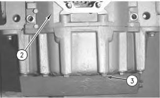

Illustration 2
g00549821
2. Remove bolts (3) that hold the oil pan to the bottom of front housing (2).
3. Remove front housing (2) and the gasket.
Copyright 1993 - 2019 Caterpillar Inc. All Rights Reserved. Private Network For SIS Licensees.
Previous Screen
Product: BACKHOE LOADER
Model: 428B BACKHOE LOADER 7EJ
Configuration: 428B Backhoe Loader 7EJ06000-09446 (MACHINE) POWERED BY 3054 Engine
Disassembly and Assembly
3054 Engine for Caterpillar Built Machines
Housing (Front) - Install
SMCS - 1151-012
Installation Procedure Table 1
Required Tools
NOTICE
Keep all parts clean from contaminants.
Contaminants may cause rapid wear and shortened component life.
1. Replace the gasket.
2. Apply Tooling (A) to the bottom portion of the gasket.
Shutdown SIS
3. If necessary, install the studs (not shown) to the back of the front housing (2) that holds the fuel injection pump in position. Tighten the studs to a torque of 11 N·m (97 lb in). Install the gasket and front housing (2). Cut the gasket to the correct length, if necessary.
4. Install bolts (3) that hold the engine oil pan to the bottom of the front housing. Tighten the bolts to a torque of 22 N·m (16 lb ft).
Illustration 1
g00549821
Illustration 2
g00549819
Illustration 3
g03549798
5. Install all bolts (1) that fasten the front housing (2) to the cylinder block and to the oil pan. Tighten bolts (1) to a torque of 22 N·m (16 lb ft) using the sequence in Illustration 3.

Note: Ensure that the bottom of the front housing is aligned with the bottom of the cylinder block.
End By:
a. Install the camshaft gear.
b. Install the front gear group.
c. Install the engine oil pan.
Copyright 1993 - 2019 Caterpillar Inc.
All Rights Reserved.
Private Network For SIS Licensees.
Tue Nov 26 18:03:42 UTC+0800 2019
Previous Screen
Product: BACKHOE LOADER
Model: 428B BACKHOE LOADER 7EJ
Configuration: 428B Backhoe Loader 7EJ06000-09446 (MACHINE) POWERED BY 3054 Engine
Disassembly and Assembly
3054 Engine for Caterpillar Built Machines
Valve Mechanism Cover - Remove and Install
SMCS - 1107-010
Removal Procedure
NOTICE
Keep all parts clean from contaminants.
Contaminants may cause rapid wear and shortened component life.
Shutdown SIS
NOTICE
Care must be taken to ensure that fluids are contained during performance of inspection, maintenance, testing, adjusting and repair of the product. Be prepared to collect the fluid with suitable containers before opening any compartment or disassembling any component containing fluids.
Refer to Special Publication, NENG2500, "Caterpillar Tools and Shop Products Guide" for tools and supplies suitable to collect and contain fluids on Caterpillar products.
Dispose of all fluids according to local regulations and mandates.
Note: The engines are equipped with either an aluminum valve cover or with a composite valve cover. The aluminum valve cover has a seal that fits between the valve cover and the inlet
manifold. The composite valve cover has a seal that is permanently fixed to the side of the valve cover.

Illustration 1

Typical example
g00547002
Illustration 2
Aluminum valve cover
g00547003
Thank you very much for your reading. Please Click Here. Then Get COMPLETE MANUAL.NOWAITING

NOTE:
If there is no response to click on the link above, please download the PDF document first and then clickonit.
Illustration 3
Composite valve cover
1. Loosen hose clamp (1) .
2. Disconnect breather hose (2) .
3. Remove three nuts (3), steel washers (6), and sealing washers (8) .

g00547004
Note: When you remove nuts (3), ensure that the nuts on the rocker arm bracket are not loosened.
Note: Current production engines have an additional shim washer (7) .
4. Remove valve cover (4), gasket (10), and seal (5) .
5. Remove seal (9) for the oil filler cap.
Installation Procedure
Note: The engines are equipped with either an aluminum valve cover or with a composite valve cover. The aluminum valve cover has a seal that fits between the valve cover and the inlet manifold. The composite valve cover has a seal that is permanently fixed to the side of the valve cover.
Illustration 4 g00547002
Typical example
Illustration 5 g00547003
Aluminum valve cover
Illustration 6 g00547004
Composite valve cover
1. Inspect the condition of the gaskets and the seals. Replace the gaskets and the seals, if necessary.
2. Install seal (9) for the oil filler cap, if necessary.
3. Apply 8T-9022 Silicone Gasket to gasket (10) .
Note: Ensure that the flat face of the gasket is toward the valve cover.
4. Install gasket (10), seal (5), and valve cover (4) .
5. Lubricate three nuts (3) with clean engine oil.
6. Install three nuts (3), steel washers (6), and sealing washers (8) .
Note: When you install three nuts (3) without shim washers (7), tighten the nuts to a torque of 20 N·m (15 lb ft). Do not overtighten the nuts.
Note: When you install three nuts (3) with shim washers (7), tighten the nuts to a torque of 30 N·m (22 lb ft). Do not overtighten the nuts.
7. Connect breather hose (2) .
8. Tighten hose clamp (1) .
Shutdown SIS
Previous Screen
Product: BACKHOE LOADER
Model: 428B BACKHOE LOADER 7EJ
Configuration: 428B Backhoe Loader 7EJ06000-09446 (MACHINE) POWERED BY 3054 Engine
Disassembly and Assembly
3054 Engine for Caterpillar Built Machines
Rocker Shaft and Pushrod - Remove
SMCS - 1102-011; 1208-011
Removal Procedure
Start By:
a. Remove the valve mechanism cover. Refer to Disassembly and Assembly, "Valve Mechanism Cover - Remove and Install".

NOTICE
Keep all parts clean from contaminants.
Contaminants may cause rapid wear and shortened component life. Illustration
g00635152