

2
3
0NDA Corporation Hydrophone Handbook September 2022 30 YEARS

For the 30 years that we have been a part of the ultrasound community, we have learned and continue to learn the expanses of advanced applications that demand acoustic measurements. This is our motivation to perfect the “art” of building the highest quality hydrophones available. We sincerely thank you for your continuous support. Team
TheSincerely,Onda
We are pleased to present the third edition of the Hydrophone Handbook! This updated version includes edits and additional content, many of which were prompted by questions and feedback from folks like yourself in the ultrasound community. So, what is new? Here are some highlights:
• Updated datasheets with fresh numbers and plots
0NDA Corporation 5
The first edition of the Hydrophone Handbook was wellreceived and we are pleased to present a second edition. This updated version includes a list of edits, many of which were prompted by questions and f
• Updated to review current product offerings
Letter to our Readers
This year, Onda celebrates a milestone. Onda is 30 years young! Along with this accomplishment, Onda is proud to have provided over 5,000 hydrophones globally to users across multiple application segments.
Letter to our Readers
Contents Hydrophone Handbook 1. Overview 2. Choosing a Hydrophone 2.1 Applications 2.2 Frequency Response 2.3 Pressure Range 2.4 Spatial Resolution 2.5 Reflection Profile 2.6 Directivity 3. Choosing a Preamplifier 3.1 Frequency Response 3.2 Switchable or Non switchable 4. Hydrophones at a Glance 5. Preamplifiers at a Glance 6. Product Nomenclature 7. Connecting your Hydrophone 8. Calibrations 8.1 Introduction 8.2 Why Calibrate 8.3 How often 8.4 Methodology 8.5 Calibration Uncertainty 8.6 Considerations Regarding Electrical Loading Conditions 8.7 Other Common Calibration Units 9. Best Practices 9.1 Handling 9.2 Environment 9.3 Measurements 9.4 Calibrations 10. Troubleshooting 11. Frequently Asked Questions 12. Glossary of Terms 0NDA Corporation 6
Appendix 1.Datasheets HydrophonesHMMembrane Hydrophones – HGL “Golden Lipstick” Hydrophones – HNP Needle Hydrophones HNC Needle Hydrophones HNR Needle Hydrophones HNA Needle Hydrophones HFO Needle Hydrophones HCT PreamplifiersHydrophonesandAccessoriesAH-2010SubmersiblePreamplifier AH-2020 Submersible Switchable Preamplifier AG 2010 Submersible Preamplifier ATH 2000 Submersible Attenuator 2.Sample Hydrophone Connections Diagnostic Imaging – HIFU 3.Ordering Information 4.Resources Calibrations Standards and Regulations 5.Warranty Policy 0NDA Corporation
8
A hydrophone, from the Greek hydro (water) and phone (sound), is a microphone that detects acoustic signals, such as sound pressure, underwater. Most hydrophone sensors are made of piezoelectric materials which convert mechanical energy to electrical energy. The acoustic pressure detected is converted to a voltage output which can be acquired and analyzed using an oscilloscope. An alternative method using fiber optics to detect changes in the refractive index from acoustic pressure changes in water has also been developed to withstand extremely high acoustic Hydrophonespressures. are used across a wide array of ultrasonic applications, ranging from the qualification of medical ultrasonic transducers to non-destructive testing. For each, there are unique performance requirements which are met through novel manufacturing processes. Differences in the material, aperture size, and physical profiles make different hydrophones better suited for various environments and applications. It is important to understand the trade offs involved to determine the best hydrophone for your needs.
0NDA Corporation
1. Overview What is a Hydrophone?


P (rarefactional) P+ (compressional)

Construction
Overview Hydrophone Handbook
The general construction of a needle hydrophone consists of a piezoelectric sensing material (e.g., ceramic or PVDF) and electrodes in contact with opposite sides. The sensor is mounted to a supporting structure and is affixed to an absorbent backing material to increase the mass which limits any ringing at the resonant frequency of the its piezoelectric material. A physical schematic of a needle hydrophone is shown below: Sound Field
V
-+ 0NDA Corporation 10
Piezoelectric SupportingBackingMetallizationSensorLayerMaterialPassivationLayerStructure
Overview An equivalent electrical circuit representing the hydrophone measurement is shown below: 0NDA Corporation http://web.stanford.edu/class/me220/data/lectures/lect10/lect_6.htmlReference: QWhere:=Charge produced from applied pressure Rx = Resistance of piezo Cx = Capacitance of piezo Cc = Capacitance of cable Ca = Capacitance of amplifier circuit Ra = Resistance of amplifier circuit V = Measured voltage V t Q Rx Cx Cc RaCa + V Oscilloscope


2. Choosing a Hydrophone
2.1 Applications
Hydrophones have been widely adopted for medical ultrasound applications for several reasons. They offer a combination of high temporal and spatial resolution, and are relatively compact and affordable to use.
Water has been established as a good standard measuring medium because it is cheap, readily accessible, and simulates the acoustic properties of tissue. However, hydrophone measurements are not always representative of clinical conditions because of differences in attenuation, which varies as a function of frequency and distance from the transducer between water and tissue. To account for this discrepancy, a derating factor or in situ factor is commonly applied to the acoustic output measured in water for medical applications.
Hydrophone Handbook 0NDA Corporation 12
• Wide frequency range and flat frequency response Wide dynamic range and low inherent noise High spatial resolution • Minimal influence on the measured sound field Selection criteria should not be considered in isolation. Many of the parameters are interdependent. Understanding the trade offs is key to determining the appropriate hydrophone.
•
•
There are many factors to consider when selecting a hydrophone. Sensitivity, frequency response, durability, and cost must all be taken into account in making the best choice for a specific application.
A list of general hydrophone requirements is given below:
a
Choosing Hydrophone
Understanding the application is a good starting point to help select the appropriate hydrophone. The ranges of key acoustic parameters will vary for different applications. The table below was adapted from information published in “Output Measurements for Medical Ultrasound” (1991). BroadbandImaging 1 ImagingNarrow-band2 therapyPhysio 3 HIFU / HITU 4 Lithotripsy Pressure (MPa) 1 8 1 5 0.1 0.3 Up to 50 10 100 (mW/cmIspta2) 720 720 Up to 3000 Up 80,000to N/A 5 Total(W)Power 0.002 0.25 0.02 0.25 Up to 15 2 500 N/A 5 Frequency(MHz) 1 60 2 30 0.75 3.0 0.25 10 0.2 0.9 Bandwidth(MHz) 6 40 0.05 0.05 40 40 Notes: 1 Broadband imaging: typically gray scale (such as B mode, Tissue Harmonic), M-mode, or A-mode 2 Narrowband imaging: typically Doppler (pulsed or CW) or color Doppler 3 Physiotherapy: refers to traditional diathermy devices as covered under IEC 60601 2 5 4 HIFU/HITU: high field strength ultrasound therapy not covered under lithotripsy or physiotherapy 5 Power and intensity are extremely low for typical physiotherapy applications because of low duty factor and repetition rate 6 Bandwidth refers to typical bandwidth requirements for the hydrophone, due to presence of nonlinear harmonics due to nonlinear properties of water i.e., this is typically greater than imaging bandwidth or the bandwidth of driving or receiving electronics 0NDA Corporation
Choosing a Hydrophone Hydrophone Handbook 0NDA Corporation 14 100 MPa 100 kHz 1 MHz 10 MHz 10 MPa 1 MPa Frequency PressureAcoustic Diagnostic Therapeutic SculptingBody FibroidsUterine Lithrotripsy FibrillationAtrial DrugThrombolysisDeliveryPhysiotherapy Scar Tissue BoneBloodHealingflowSonographyEndoscopy TreatmentCancer IVUS Hyperthermia Applications Map An applications map below depicts common medical applications and their respective frequency and pressure range.

A hydrophone’s frequency response refers to the way a hydrophone responds to different frequencies, i.e., the output voltage at a given pressure amplitude with regard to frequency. An ideal “flat” response means that the hydrophone is equally sensitive at all frequencies without any regions of exaggeration or attenuation. However, there are many design considerations (e.g., inherent resonant frequencies, backing material, electrical impedance) that make this a challenging goal to achieve. Invariably, all hydrophones exhibit some deviation. It is common to describe a hydrophone being flat within a given frequency range within some tolerance. For instance, the HM membrane hydrophone is flat from 0.5 to 45 MHz within ± 3 dB. The plot below summarizes the useable frequency response for different hydrophone models.
0.01 0.1 1 10 100 HM HGL HNP HNC HNR HNA HFO HCT Frequency Range [MHz] ModelHydrophone ± 3 dB ± 6 TBDdB 0NDA Corporation
Choosing a Hydrophone
2.2 Frequency Response
Choosing a Hydrophone -295 -285 -275 -265 -255 -245 -235 -225 -215 0.01 0.1 1 10 100V/1re[dB]Sensitivity m Pa Frequency [MHz] HCT-0320HMB-0500HNR-0500HNA-0400HNC-0200HNP-0200HGL-0200
Membrane Hydrophones (HM) For most pulsed wave imaging applications that require a flat response over a broad bandwidth, membrane hydrophones are the gold standard. Needle Hydrophones (HN)
The HGL series hydrophones bridge the gap in performance and ease of use between membrane and needle hydrophones. They offer a flatter frequency response than needle hydrophones, with a more convenient form factor than membranes.
Hydrophone Handbook 0NDA Corporation 16
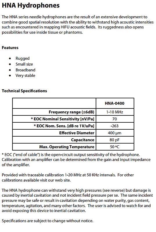
The ceramic based HNC models have good sensitivity for their size, but their frequency response is less flat. The polymerbased HNP models have a smoother frequency response, with about 10 dB less sensitivity for a given aperture relative to the HNC. The HNR hydrophones are well suited for harsh environments, but have a characteristic resonance at 2 MHz. The HNA was designed to measure HIFU acoustic fields with a flat response between 1 and 10 MHz. Needle hydrophones are the best choice where a low reflection profile is critical. Capsule or “Golden Lipstick” Hydrophones (HGL)
Choosing a Hydrophone Fiber Optic Hydrophones (HFO)
Hydrophones to Measure Cavitation (HCT)
0NDA Corporation
Example Spectrum for 1.44 MHz HIFU Transducer

HCT hydrophones are designed to measure acoustic fields in harsh environments with cavitation. Piezoelectric sensors are encapsulated in a protective Teflon material to ensure durability. The useful frequency range support common frequencies used for ultrasonic cleaning starting from 20 kHz and up.
Optical fiber hydrophones are designed to uniquely support very high intensity fields for applications such as HIFU and lithotripsy, providing both acoustic pressure and temperature measurements simultaneously. Whereas traditional piezoelectric hydrophones are susceptible to damage, the HFO based on the Fresnel Reflection principle, can withstand acoustic pressures up to 500 MPa at wide bandwidths.
Choosing a Hydrophone Hydrophone Handbook 0NDA Corporation 18
Generally, more sensitive hydrophones have larger sensing areas. The trade-off in lower spatial resolution and narrower acceptance angle (or directivity) should be noted, however. Choosing a Hydrophone -290 -280 -270 -260 -250 -240 -230 -220 0 5 10 15 20 25V/1re[dB]Sensitivity m Pa Frequency [MHz] HGLHGLHGL-0085-0200-0400 Effect of Sensing Area on Sensitivity 0NDA Corporation
Choosing a Hydrophone
Amplifiers have a voltage limit beyond which they become non linear and saturate. This is a reversible problem. That is, if it happens it does not damage the hydrophone or preamp. Although the data is invalid, the hydrophone can still be re used within the amplifier’s specified voltage range. For Onda’s modular amplifiers (i.e., AH 20x0, AG 20x0), a maximum voltage output is provided as a specification. The formulas to calculate loaded sensitivity can be used to determine the expected acoustic pressure level of the signal to verify they will be within the linear range of the amplifier. For high sensitivity hydrophone models, Onda also offers a signal attenuator (i.e., ATH 1000) to prevent preamplifier saturation. For membrane hydrophone models which have an integral preamplifier, the maximum linear pressure range is also provided as a 2.specification.Hydrophone Damage Unlike preamp linearity, damage thresholds are much more difficult to provide. Hydrophones are intrinsically fragile, particularly near the sensing element, because they are designed to have high sensitivity to detect transient pressures. Different models have varying degrees of protection depending on the construction. To add to the complexity, the robustness of each hydrophone depends on several factors in the test
Maximum Dynamic Pressure and Intensity
1. Linearity of Preamplifier
There are two general considerations for determining the maximum pressure at which a hydrophone can be used: (1) the linearity of its preamplifier, and (2) hydrophone damage.
Hydrophone Handbook 0NDA Corporation 20
Choosing a Hydrophone environment. For instance, it is particularly important to minimize the dissolved oxygen content in water to limit bubble formation which increases the likelihood of cavitation damage. Other factors that contribute to the likelihood of damage include drive frequency, duty cycle, and temperature.
The following plot estimates the pressure range that can be measured with each hydrophone model. However, it should be noted these are only guidelines. It is important that the user considers the details of other factors that contribute to the actual pressure thresholds (e.g., aperture size, preamplifier noise, water quality, drive conditions, etc.).
0NDA Corporation
The only pressures that are clearly acceptable for all circumstances are below approximately 100 kPa. This is particularly true for continuous or quasi-continuous waves, which at pressures higher than 100 kPa make the hydrophone more susceptible to cavitation damage. So from a conservative point of view, the only clearly safe conditions are below 100 kPa peak negative pressure. Nevertheless, user history has indicated that certain hydrophone models have been used successfully under the following conditions: • HGL and HM: intended to be used to measure pressure amplitudes for diagnostic B and A mode ultrasound of one to three cycles of excitation with low duty factor (~ 1%). Stress tests on these devices also indicate that they should withstand short bursts (1-2 cycles) of pressure less than 3 MPa x [fc/1 MHz ]1/2 where fc is the center frequency in MHz. For example, a 1 MHz field indicates a negative pressure of 3 MPa, whereas a 4 MHz field corresponds to a maximum negative pressure of 6 MPa.
All these results were obtained in well degassed water with an oxygen concentration less than 4 ppm. Users are advised that many models may work at higher pressures, but when measuring under such conditions, users need to carefully monitor signals on the oscilloscope for instability of the hydrophone signal. If any flickering or waveform unsteadiness is observed, the driving levels should be reduced.
• HNA: intended to be used for pressure amplitudes representative of HIFU applications. These devices are tested at the focus of a 1.5 MHz source, operated at 50% duty cycle in deionized, degassed water at 23 degrees C. This provides an exposure intensity of 715 W/cm2 temporal-average and 1430 W/cm2 pulse-average, corresponding to 15 MPa peak compressional and 3.7 MPa rarefactional pressure.
Choosing a Hydrophone
Hydrophone Handbook 0NDA Corporation 22
• HNP and HNC: intended to be used for Doppler modes of less than 720 mW/cm2 .
• HFO: intended to be used for very high pressure applications such as lithotripsy. Successful measurements have been made up to 75 MPa (P+) and 11 MPa (P ) under controlled environment.
Choosing a Hydrophone
In addition to mechanical damage from high acoustic pressure, another mechanism that can damage the hydrophone is heat. That is, some of the intensity of the ultrasound field can create thermal damage to the hydrophone. In most cases, the pressure considerations are the operative concern for hydrophone measurements because pressure limits are reached before the hydrophone can heat up due to the intensity from water convection (Onda’s hydrophones are designed to measure only in water). An exception is the HMB hydrophone, because its rubber backing does not allow convective cooling. Therefore, it is recommended to keep intensities below diagnostic ultrasound levels of 720 mW/cm2 . Note also that each hydrophone data sheet has a maximum water temperature in which a hydrophone can be submerged.
0.001 0.01 0.1 1 10 100 1000 HM HGL HNP HNC HNR HNA HFO HCT Measurable Pressure Range [MPa] ModelHydrophone Measurable Pressure Range for Different Hydrophones 0NDA Corporation
The hydrophone sensing area needs to be chosen to achieve adequate spatial resolution of the beam. Otherwise, the spatial peaks will be underestimated and the beamwidths will be overestimated. For this reason, Onda’s hydrophones are offered with a range of aperture sizes from 85 μm to 1500 μm. The IEC recommends a method to select the correct hydrophone size which requires a less detailed knowledge of the field. As discussed in Section 5.1.6.1 of IEC 62127-1: The effective radius of the element should ideally be comparable with or smaller than one quarter of the effective wavelength, so that phase and amplitude variations do not contribute significantly to measurement uncertainties. It is not possible, because of the large range of types of ultrasonic transducers, to establish a simple relationship between the optimum effective element size of the hydrophone and parameters such as the ultrasonic transducer dimension, the effective wavelength and the distance from the ultrasonic transducer. However, in the far field it is reasonable to relax the above criterion. For unfocused circular ultrasonic transducers, the following criterion may be used as a guide to the determination of the maximum effective radius amax of a hydrophone active element. amax is given by: (6) Where: a1 is the effective radius of the ultrasonic transducer; l is the distance between the hydrophone and the source aperture plane λ is the effective wavelength corresponding to the acoustic working frequency.

2.4 Spatial Resolution
Choosing a Hydrophone Hydrophone Handbook 0NDA Corporation 24
Choosing a Hydrophone 0NDA Corporation
For a focusing ultrasonic transducer, the formula (6) may still be used. For an ultrasonic transducer with a non circular element, the formula may be used by replacing a1 by one half the maximum ultrasonic transducer dimension or ultrasonic transducer element group dimension.
As an example, consider a circular F/2 transducer (i.e., whose focal distance is twice the value of its diameter). In this case l = 4a1 so the hydrophone radius should be approximately half of the wavelength.

Hydrophone (HN) Mount 3.5 MHz Pulsed Wave Needle Membrane
Using
2.5 Reflection Profile
Hydrophone Handbook Choosing a Hydrophone 0NDA Corporation 26

It is preferable to use a sensor that does not affect the parameter being measured, which depends on the nature of the acoustic field. Needle type hydrophones have a good reflection profile and are preferred for continuous wave fields. Pulsed fields, on the other hand, are more forgiving because the effect of reflections can be separated by time with the use of an Thereoscilloscope.aregenerally three types of hydrophone profiles: (1) needle, (2) capsule, and (3) membrane.

TransducerNeedle Capsule a schlieren system, it is possible to visually compare how the acoustic reflections behave for different reflection profiles.

HydrophoneNeedle(HN) At T1 Wave propagates from transducer At T2 Wave hydrophonereachessurface At T3 Minimal transmittedHGL;detectedreflectionswithHNandreflectedandwave observed with HM Capsule HydrophoneHydrophone(HGL)Membrane(HM) Choosing a Hydrophone 0NDA Corporation

2.6 Directivity Directivity refers to the variation in sensitivity relative to the angle of incidence of the acoustic signal on the sensing element of the hydrophone. At a fixed frequency, smaller sensing areas are more omnidirectional and less affected by off-angle Formeasurements.instance,at45° incidence the HGL 0085 (85 μm aperture) has a relative signal amplitude of 0.8 under a 5 MHz signal, compared with an HGL-1000 (1000 μm aperture) which has a relative amplitude of 0.05.

Deg+45Deg45 0 Deg TransducerHGLMountPulsed Wave HGL Hydrophone Directivity at 5 MHz Hydrophone Handbook Choosing a Hydrophone 0NDA Corporation 28

Onda’s hydrophones are calibrated with respect to a plane wave. The hydrophone is positioned so that its active surface is parallel with the planar wavefront, i.e., the direction of propagation of the wave is normal to the active surface of the hydrophone. For example, in the case of needle or capsule hydrophones, the active surface is at the tip, so the normal is the major axis of the needle or capsule. The hydrophone’s sensitivity decreases as it is rotated with respect to the normal position. For needle and capsule hydrophones the sensitivity approximately follows formula 1: �� ��,�� = 1+cos(��) 2 × 2��1(����sin �� ) (����sin �� ) (1) where:D=directivity
Estimating Hydrophone Directivity
function (voltage out of the hydrophone relative to voltage when an incoming wave is normal to the tip) = the angle relative to the normal f = frequency J1 = Bessell function of the first kind k = wave number (2 / wavelength) = 2 f /c where c is the wave speed = 1500 m/s in water a = radius of the hydrophone (0.5 mm approximately for an HNC-1000, for example) a
0NDA Corporation Choosing
Hydrophone
HGL Pulsed Wave Hydrophone Handbook Choosing a Hydrophone 0NDA Corporation 30
For high frequencies and small angles the (1+cos()) term becomes negligible and the formula becomes: �� ��,�� = 2��1(����sin �� ) (����sin �� ) (1b) Furthermore, for small angles as well as low frequency Eq. (1b) may be approximated as: �� ��,�� = 2��1(2�������� ��) (2�������� ��) (1c)
From (1c) it can be seen that for small angles and low frequency the directivity will scale with f where f is the frequency. That means that under such conditions you can take the directivity pattern acquired at one frequency f1, and estimate the directivity pattern at another frequency f2 from the same curve, replacing theta with theta * f1/ f2. For example, if at 5 MHz the directivity is 0.9 at 10 degrees, at 2.5 MHz it will be 0.9 at 20 degrees. Onda provides typical directivity patterns measured at 5 MHz for this purpose. The user should be aware, however, that Eq. (1c) loses accuracy at very low frequencies, as can be seen from Eq (1), which is the more exact formula.
Onda’s preamplifiers are designed as an electronic and mechanical match with the hydrophones. The AH and AG series preamplifiers add a 20 dB gain. There are a few items to consider when choosing a preamplifier.
The AH-20x0 submersible preamplifiers are available with a 100 MHz bandwidth (denoted by 100 after the model number). The bandwidth of the AG 20x0 preamplifiers is 60 MHz. Their downward sloped frequency response compensates for the characteristic high frequency sensitivity of the HGL hydrophones to provide a flatter combined response. Therefore, the AG series preamplifiers are generally recommended for HGL hydrophones while the AH preamplifiers are recommended for other hydrophone models.

3.1 Frequency Response
3. Choosing a Preamplifier 0NDA Corporation 0 5 10 15 20 25 0 20 40 60 80 100 [dB]Gain Frequency [MHz] AH-2010-100 (260 μVrms) (360 μVrms) Preamplifier (Noise Level)

-250-252-254-256-258-260 -248 -240-242-244-246 0 10 20 30 40 50 V/1re[dB]Sensitivity m Pa Frequency [MHz] HGL-0200 + AH-2010 HGL-0200 + AG-2010 3.2 Switchable or Non-switchable The preamplifiers are available either with a single 20 dB gain (AH-2010, AG-2010) or switchable gain (AH-2020), where the gain can be easily switched from 0 dB to 20 dB. The switchable gain preamplifiers come with a separate calibration at each gain setting, and provide the convenience of not having to remove the preamplifier for different measurements. Note the flatness of the HGL sensitivity coupled with the AG preamplifier. HGL-0200 + AH-2010 HGL-0200 + AG-2010 Hydrophone Handbook Choosing a Preamplifier 0NDA Corporation 32
0NDA Corporation
4. Hydrophones at a Glance HM HGL HNP HNC ElectrodeSize[µm] 200, 500 85, 200, 400 200, 400 400, 1000 Freq. Range[MHz] 0.5 45 (±3 dB) 0.25 40 (±3 dB) 1 20 (±6 dB) 1 10 (±6 dB) SensitivityNominal Medium Medium Medium High Ruggedness Low Medium Low Low DisturbanceField High Low Low Low ApplicationsCommon StandardPulse, Regulatory Pulse + GeneralCW, Regulatory GeneralCW, purpose, Doppler acousticsPurpose,GeneralCW,Photo Cost $$$ $$ $$ $$ Hydrophone Handbook 0NDA Corporation 34


HNR HNA HFO HCT-03x0 500, 1000 400 100 <1500 1 10 (±6dB) 1 10 (±6dB) 0.0001 100 (±3dB) 0.03 1.2 Low Low Low Medium High High High High Low Low High Low HIFU HIFU HIFU, Lithotripsy Cavitation $$$ $$$ $$$$ $$$ 0NDA Corporation


5. Preamplifiers at a Glance AH-2010-100 AH-2020-100 Gain / Attenuation* 20 dB 0Switchable:and20dB Freq. Range [MHz] 0.05 100 0.05 100 Noise [μVrms] 360 0dB: 20dB:1500560 Submersible YES YES Commonly Pairedwith: HNP, HNC, HNA HNA Cost $$ $$$ Hydrophone Handbook 0NDA Corporation 36

AG 2010 ATH 2000 20 dB 20 dB* Range [MHz] 0.05 60 DC to 100 [μVrms] 260 Submersible YES YES Commonly Paired HGL AHHNA,2020 Cost $$ $ 0NDA Corporation * Nominal value at 2 MHz


Hydrophone Handbook 0NDA Corporation 38
6.
The second letter indicates the family type, such as “N” for needle or “M” for membrane.
Hydrophones
Similar to the hydrophones, the first letter represents the product, “A” for amplifier (or preamplifier). The second letter “H” indicates that the preamplifier is to be coupled with a hydrophone. The first 2 numbers, “20”, indicate the device is submersible. For the submersible preamps, the second 2 numbers describe if the amplifier is switchable. “10” represents a fixed gain; “20” represents a gain that is switchable between 0 and 20 dB. The numbers that follow indicate the bandwidth. “ 100” represents a 100 MHz bandwidth.
The third letter describes the attribute of the hydrophone. For example, “P” is for polymer and “C” is for ceramic. The numbers at the end typically describe the electrode size in microns. The exceptions include the HFO and HCT, which describe the laser wavelength and the useful frequency, respectively.
Onda’s nomenclature system has been designed to describe the products by their family type, attribute, and aperture size. For most hydrophones, the product name is made of 3 letters, followed by 4 numbers.
The first letter is the product, “H” for hydrophone.
H N P 0 2 0 0 A H 2 0 1 0 1 0 0 0NDA Corporation
Hydrophone and NomenclaturePreamplifier
Preamplifiers
7. Connecting Your Hydrophone Hydrophone Handbook 0NDA Corporation 40 50 Ω Preamplifier • Submersible • Non switchable • 20 dB AH/AG-2010DC Block Preamplifier • Submersible • Switchable • 0, 20 dB AH-2020DC Block 1 MΩ Oscilloscope BNC(M) 50 Ω Adapter BNC(M) BNC(F) 20 or 100 cm Cable BNC(M) SMA(M) Right Angle Adapter SMA(F) SMA(M) Adapter SMA(F) BNC(F) Other Accessories Used if oscilloscope only has 1 MΩ setting To interface between preamp and DC block or hydrophone directly to oscilloscope To connect preamp/attenuatorhydrophonebetweenand To interface between HNR and preamp BNC(M) SMA(F) SMA(F) SMA(M)SMA(M)BNC(F)BNC(F)BNC(F)BNC(F)


0NDA Corporation Golden Lipstick HGL-series HNA,NeedleHNP,HNC HN-series HMA,MembraneHMB HM-series Fiber Optic HFO-series Integral Cable HNR-series Attenuator • Submersible • 20 dB ATH-2000 SMA(F) SMA(F)SMA(F)SMA(F)SMA(F)BNC(M)SMA(M)


• Ultimately,
An acoustic calibration of a hydrophone determines the sensitivity as a function of frequency. This is measured in terms of units of electrical output (volts) per unit of physical pressure (Pascal) over a frequency range (Hz). These fundamental units provide a reference for the calibration and allow different measurements to be compared. The calibration methods are well defined and accepted internationally, while the accuracy of the calibration is carefully determined with a known uncertainty. Traceable calibrations mean the calibrations are reliably traced back to a primary calibration laboratory, such as National Physical Laboratory (NPL) in the United Kingdom or Physikalisch-Technische Bundesanstalt (PTB) in Germany. make sure measurements are accurate and comply with standard methods that are universally accepted verify the accuracy and stability of the measurement system account for local test conditions such as temperature variations to create confidence in measurement results How often? Typically hydrophones are calibrated once per year.
Hydrophone Handbook 0NDA Corporation 42
8.3
8.2 Why Calibrate? Calibrations should be done: • To
• To
8.1
• To
8. Calibration Introduction
8.4 Methodology
Onda's calibrations are accomplished through the use of reference equipment calibrated at a national laboratory such as National Physical Laboratory (NPL) in the UK or Physikalisch Technische Bundesanstalt (PTB) in Germany. The particular reference equipment and national laboratory used for any calibration is referenced on the calibration certificate. Calibration is obtained by comparison techniques to reference hydrophones. For calibration below 20 MHz, the stepped single frequency comparison technique is used, and for calibration above 20 MHz, the harmonic comparison technique is employed. The procedures are as follows: Stepped Single Frequency Comparison Technique: 1) The reference hydrophone is placed at the focus of a broadband source [1], which is driven by a sinusoidal tone burst. The reference hydrophone is aligned by maximizing the hydrophone signal with the source driven at the maximum end of its frequency range (20 MHz for a 1-20 MHz calibration, 5 MHz for a 0.25 1 MHz calibration). The voltage driving the source is then swept in across the frequency range (i.e., 1 to 20 MHz, or 0.25 to 1 MHz). At each frequency, the output of the reference hydrophone is measured and digitally filtered to separate the primary frequency component from any harmonics that may be present in the signal. The reference hydrophone has previously been calibrated by NPL, so that the voltage it detects can be translated into a pressure value, hence calibrating the pressure output of the source as a function of frequency at the source’s focal position.
Calibration
0NDA Corporation
Calibration
Harmonic Comparison Technique: 1. The reference hydrophone is placed at a position in the nonlinear acoustic field produced by a plane circular source transducer driven by a 2.25 MHz sinusoidal tone-burst signal. The position is chosen where many strong harmonics of the fundamental frequency are generated in the distorted pressure waveform due to non linear propagation. Using a 50 MHz high pass filter, the reference hydrophone is aligned by maximizing the hydrophone’s high frequency components in the plane at that position to an optimal orientation. The pressure waveform at that position is recorded after the high pass filter is removed. An FFT of the waveform is calculated, and the voltage amplitude at each harmonic is determined. The reference hydrophone has previously been calibrated by NPL, so that the voltage it detects can be translated into a pressure value, hence calibrating the pressure output of the source at each harmonic.
The reference hydrophone is then replaced by the hydrophone to be calibrated and re aligned. The voltage driving the source is again swept across the same frequency settings, and the output of the hydrophone at the fundamental of the driving signal is determined and recorded. This voltage is then divided by the pressure amplitude (measured in step 1) to determine the output of the hydrophone in Volts per Pascal (V/Pa).
Hydrophone Handbook 0NDA Corporation 44
8.5 Calibration Uncertainty
0NDA Corporation
The uncertainties in the calibration are predominantly systematic in origin. The random error is negligible in comparison. The dominant source of uncertainty is the uncertainty in the calibration of the reference hydrophone (as provided by NPL). The other sources of uncertainty are temperature variation (± 1 °C, resulting in calibration variations of ± 1%) source stability (± 2%) digitizer error (± 2%) and positional repeatability (this effect varies with frequency, from ± 2.5% at 1 MHz to ± 5% at 20 MHz). The combined effect of these error sources is calculated according to [2-3], with a coverage factor of k = 2 to calculate the uncertainty with a 95% confidence level. This yields uncertainties that are typically within ± 1.5 dB from 0.5 to 1 MHz, ± 1 dB from 1 to 15 MHz, ± 1.5 dB from 15 to 20 MHz, ± 2.2 dB from 20 to 40 MHz and ± 3 dB from 40 to 60 MHz.
Calibration
2. The reference hydrophone is replaced by the hydrophone to be calibrated, which is then aligned the same way at the same position as the reference hydrophone. The pressure waveform is recorded with the absence of the high pass filter. An FFT of the pressure waveform is then calculated, and the voltage at each harmonic is determined. This voltage is then divided by the pressure amplitude (measured in step 1) to determine the output of the hydrophone in Volts per Pascal (V/Pa).
EOC
����
CH = capacitance
Customers are advised to perform their own assessment of the accuracy of the above equation fore their configuration. In particular, customers should be aware that extension cables connecting the hydrophone to the preamplifier or detector
CH =
= �� �� ����(��) ���� ���� +����+���� Where:G(f) =
Calibration Hydrophone Handbook 0NDA Corporation 46 8.6
Note that the HGL, HNP, and HNC hydrophones may be connected directly to an amplifier without any cable, so the EOC sensitivity is defined as the sensitivity that would be measured at the hydrophone's connector into an infinite load. If the hydrophone and amplifier impedances are primarily capacitive, the loaded sensitivity, �� �� , can be estimated as follows: (��) amplifier gain (as a function of frequency) (f) hydrophone sensitivity capacitance of hydrophone of amplifier of connector
Considerations Regarding Electrical Loading Conditions
Because a hydrophone's sensitivity depends on the electrical impedance of the detector or amplifier to which it is attached to, modular hydrophones are sold with an open circuit calibration, called formally the "End-of-cable Open Circuit Sensitivity", or EOC sensitivity for short, and designated as Mc(f). Mc(f) is determined by measuring the sensitivity of the hydrophone with a laboratory amplifier, and then subtracting the effect of that amplifier's gain, as well as that of its finite (i.e., non infinite load).
CA = capacitance
MC
=
��
It is also common to express the calibration in terms of acoustic intensity. Strictly speaking, a simple calibration factor exists only under conditions of a sinusoidal signal and under the assumption that intensity is equal to the time-averaged value of the pressure squared divided by the acoustic impedance of the medium. Under these conditions the following relation applies: �� = �������� �� where I is the acoustic intensity, and VRMS is the root mean square voltage of the sinusoidal signal. The calibration factor K is given by: �� =���� ���� �� 2 where za is the acoustic impedance of the medium (1.5 MRayls for water). Because it is common to express I in units of W/cm2 , �� ����������2����2 �������� =1.5×10¹⁰ ���� �� ���������� ���� 2 for water.
0NDA Corporation may not be accurately modeled as purely capacitive at higher frequencies; in such cases, customers are advised to consider purchasing a separate calibration which includes the use of their extension cables. 8.7 Other Common Calibration Units ML(f) is in units of voltage divided by pressure and is typically expressed in Alternatively,V/Pa.itcan be expressed in units of dB re 1V/µPa using the following equation: ��������1�������������� ���� �� =20×������10 ���� �� 120
Calibration
7. Limit the amount of time that the hydrophone is immersed in water. If the measurement session is over, it is best to remove the hydrophone from the water to help extend the hydrophone life.
3. When connecting the hydrophone with its accessories (e.g., preamplifier, adapters, cables), it is only necessary to hand tighten. Over tightening may result in damage to the housing.
9. Best Practices
9.1 Handling:
1. The hydrophone sensing point is fragile. Avoid any physical contact, particularly near the sensing element. To remove trapped bubbles or particles at the tip, consider using a light jet of water from a squeeze bulb or a syringe for removal.
2. It is best to use the supplied hydrophone mounts which are designed to minimize handling damage as well as acoustic reflections.
Some key items to keep in mind when setting up your measurement:
Hydrophone Handbook 0NDA Corporation 48
5. Connect the power supply into the DC block as the last step in any hydrophone connection sequence. If a connection is made under load, a high shorting current arises and can damage the preamplifier.
6. A common failure is over stretching the cable because it is too short to support the necessary setup. Inquire about longer hydrophone cables if needed.
In general, it is good practice to install the hydrophone as a last step after completing all other setup items.
4. Make sure to connect the hydrophone with its preamp only when the power is disconnected.
8. Store the hydrophone in its supplied case, which is designed to ensure the sensing element is safe from handling. Keep the hydrophone in a stable and controlled environment.
0NDA Corporation
9. When sending the device(s) for recalibrations, use the originally supplied case. Package the original case in a foam filled cardboard box for shipping.
1. Use clean deionized and degassed water for high intensity measurements. Degassed water reduced the risk of cavitation damage by removing gases in the water. Using degassed water also improves the accuracy of the readings by reducing bubbles. Particulates in the water may create undesired acoustic scattering effects. Deionized water is recommended to reduce electrical coupling in strong conducting fields.
2. When measuring with membrane hydrophones, use high resistivity water. We recommend a minimum of 200 kΩ -cm because conducting water becomes a capacitive shunt across the device, which affects low frequency readings. Fresh deionized or distilled water is recommended because it typically has a high resistivity of 1 MΩ-cm or more. Routine checks of conductivity will ensure accuracy in the measurements.
3. Ensure the water temperature is stable to minimize measurement variation caused by changes from the sound velocity.
4. Minimize electrical interference from other sources which may create spurious signals in the measurements.
Best Practices
9.2
Environment:
9.4 Calibrations:
Best Practices
9.3 Measurements:
3. Use a dissolved oxygen meter to regularly monitor the dissolved oxygen level in the water.
2. Control and monitor the water temperature. Hydrophone calibrations by Onda are done at 23.5 °C.
2. Establish a calibration strategy. Some users have a second hydrophone set available to limit any measurement downtime when the primary hydrophone is sent for calibrations. Other users have established a scheme where dedicated “workhorse” hydrophones are traceable to reference hydrophones.
Hydrophone Handbook 0NDA Corporation 50
1. Establish a routine monitoring scheme to check the health of your measurement instruments. Before starting measurements, it is best to use a stable reference transducer (or “gold” standard transducer) to regularly test your acoustic measurement system. SPC tracking will help establish appropriate control limits to identify anomalies early.
4. Ensure that the impedance set on the oscilloscope matches the output impedance of the hydrophone (e.g., 50 Ω with preamplifier and 1 MΩ without preamplifier).
1. Maintain Hydrophone calibrations, typically recommended once per year. To start, complete the Hydrophone Calibration Questionnaire to specify the calibration option(s) and the hydrophone configuration.
There are many subtleties to correctly make a hydrophone measurement. Here, an outline is presented to assist in troubleshooting
2 common issues :
No Signal Detected
1. To isolate the effect of environmental factors, pulse the source (even if designed to operate in CW) to separate in time the acoustic signal from environmental interference (electrical, optical, etc.). Account for the speed of sound in water and the number of cycles.
5. Use a reference transducer and/or a second hydrophone to isolate the issue. If reference devices are not available, consider doing a pulse echo measurement or a measurement using a different method (e.g., RFB) for comparison.
3. If trying to measure a pulse, make sure that triggering is properly set up.
4. Visually inspect the hydrophone tip to ensure the quality of the electrode has not been compromised.
• No Signal Detected • Anomalous Signal Observed
2. Ensure all connections are secure and properly seated; make sure there are no damaged cables.
10. Troubleshooting
1. Determine where the signal should be by estimating distance.
6. Use a network analyzer to check the hydrophone capacitance and compare with the capacitance values done as part of the calibration. Anomalous Signal Observed
0NDA Corporation
8. Check the terminating impedance into the oscilloscope. In general, Onda hydrophones with a preamplifier should be connected to the oscilloscope with a 50 Ω impedance. If an Onda hydrophone is connected directly to a oscilloscope it should be connected with a high impedance, typically 1 MΩ in parallel with 10 to 30 pF. See section on Connecting Your Hydrophone.
2. Place the hydrophone far enough away from the source to make sure that any electrical interference has ended before the arrival of the acoustic signal
Anomalous Signal Observed cont.
5. Check to make sure transducer is insulated. Make sure the water resistivity comply with standard requirements.
3. Confirm the acoustic signal by moving the hydrophone. The acoustic signal should change, whereas an electrical signal will not.
7. Check hydrophone quality (e.g., electrode intact, mechanical integrity, exterior film)
9. Determine if the environment has excessive electrical noise and whether the source is sufficiently shielded.
6. Determine if the anomaly is intermittent or repeatable.
10. Troubleshooting
4. Check all connections are secure, particularly the ground connection.
10. Confirm the hydrophone in use has sufficient signal to noise.
11. Determine if environmental interference is present by removing the hydrophone from the acoustic field and observing the signal. Similarly, you can disconnect the hydrophone entirely.
Hydrophone Handbook 0NDA Corporation 52
The main consequence of heating a hydrophone to above 50°C is that the polymers in its structure begin to soften and so the device's structure and water sealant is compromised. At even higher temperatures, the piezoelectric material will de pole and the hydrophone will no longer be capable of acoustic measurements. What does the DC Block do? Does it affect the gain?
0NDA Corporation
The DC block powers the preamp and removes the DC component from the returned signal. It does not affect the gain. What impedance setting on the oscilloscope should be made? The impedance set on the oscilloscope should match the output impedance of the hydrophone (e.g., 50 Ω with preamplifier and 1 MΩ without preamplifier).
What happens if a hydrophone is heated above 50°C?
Hydrophones should be removed from the water if not used. How do I dry the hydrophone? If possible, rinse the hydrophone tip in distilled water at the end of a measurement session and leave to air dry. Avoid touching the hydrophone tip!
How do I select the right hydrophone for my application?
11.
Please refer to the Choosing a Hydrophone/Preamplifier section. How do I connect my hydrophone to make measurements? Please refer to the Hydrophone Connection Diagram. Can I leave my hydrophone submerged in water indefinitely?
Frequently Asked Questions
Hydrophone Handbook 0NDA Corporation 54
Frequently Asked Questions
Over what frequency range do you calibrate your hydrophones?
A primary advantage with sending devices to Onda for calibration is that they can be inspected against manufacturing QC criteria. For all re calibrations, Onda includes a free evaluation of any Onda hydrophone before commencing with the calibration. If a hydrophone issue is discovered, Onda will inform our customers and present the option to forego the costly calibration.
Can total acoustic power be measured with hydrophone? How does it compare with measurements from an RFB?
Can Onda hydrophones be used as a source or transmitter?
Yes, but it has not been established on how hard each hydrophone can be driven without damage. Because the intended design for Onda’s hydrophones are to “receive”, the damage threshold will be highly variable from one device to the next.
Yes, but a scanning system is required in order to perform a planar scan and then integrate the intensity over the plane. Typical uncertainties measuring total acoustic power with the hydrophone are typically more than 25%, whereas with the RFB they are typically less than 10% and can be as low as 5% for unfocused transducers. Making total acoustic power measurements with an RFB offers a significant throughput advantage.
What is the difference between calibrations at Onda compared with a calibration at a National Laboratory?
Onda has the capability to support acoustic calibrations from 30 kHz up to 60 MHz. Please refer to the Ordering Details section for a list of calibration options.
An End-of-Connector Open Circuit (EOC) sensitivity represents the sensitivity measured at the hydrophone connector without the preamplifier. An EOC hydrophone calibration can be mathematically converted to a preamplifier loaded calibration. See the Resources section for the white paper. Onda also can supply a software utility to combine the standalone calibration data sets. An EOC calibration offers more flexibility because it can be paired with different preamplifiers. However, the user can avoid the conversion by having hydrophones calibrated in a preamplifier-loaded configuration.
0NDA Corporation
Frequently Asked Questions Should I get an EOC or preamplifier-loaded calibration?
Please note, however, that as the frequency goes up, the mathematical conversion becomes invalid because cable transmission line effects become more important. In particular, cable resonance effects become more prevalent at high frequencies. In some cases for fairly non linear pulsed waveforms, there may be significant waveform distortion because the pressure signal contains very high frequency harmonics which excite cable resonances. In general, we recommend that the cable length be less than a tenth of the electrical wavelength in the cable for any relevant frequency. The cable electrical wavelength is given by the cable phase velocity divided by the frequency. The phase velocity can be assumed to be 2 x 10⁸ m/s, so for example, at 20 MHz the cable electrical wavelength will be 1 meter. Just bear in mind that in many practical applications nonlinear harmonics go to much higher frequencies than 20 MHz. Note that frequencies above 20 MHz require the calibration to be preamplifier-loaded to ensure sufficient sensitivity.
The HMB is an HMA back filled with absorbing material. The backing dampens vibrations of the membrane which may occur during scanning. Free membrane hydrophones are susceptible to this issue, and it is commonly suppressed either by waiting for the vibrations to dampen before taking a measurement, or by using cross correlation to filter them out. Because both of these solutions require additional time, the HMB is a good option for setups that use motorized scanning. The only other significant performance difference between the HMA and HMB designs is that the HMB is more sensitive. As mentioned in our datasheet, the HMB 0200 is about 4 dB more sensitive than the HMA 0200.
What is the difference between an HMA and HMB hydrophone?
To synchronize the hydrophone measurement with the generation of the acoustic pulse from the DUT, it is best to trigger off an electrical signal from the transducer. Most ultrasound manufacturers can supply information to access this.
An alternative method is to use an auxiliary hydrophone to detect the acoustic signal if an electrical trigger is not available. There should be some understanding of the acoustic field to help set up the acoustic trigger. For instance, a needle shaped hydrophone should be used to minimize any interference effects. Furthermore, the hydrophone should be positioned to minimize any interference effects while oriented to have sufficient sensitivity. It should also be noted that an acoustic trigger may be more suitable for certain types of transducers than others (e.g., curved arrays), as it is best to position it in line with the firing direction.
Hydrophone Handbook 0NDA Corporation 56
How do I trigger off my ultrasound Device Under Test (DUT)?
Frequently Asked Questions
Frequently Asked Questions
Yes, so long as the cable is connected after the preamplifier and the detector input impedance matches the cable characteristic impedance (should be 50 Ω). If a cable is inserted between the hydrophone and preamplifier, the cable contributes to the capacitance of the device and consequently the sensitivity will change. Additionally, there is a risk that the acoustic signal can excite cable Sectionresonances.5.1.10ofIEC
62127 1 provides a guideline for picking an appropriate length of cable: To minimize the effect of resonance in the connecting cable, the length of the hydrophone cable (in meters) shall be much less than 50/(fawf + BW 20) where fawf is the acoustic working frequency in MHz and BW 20 is the 20 dB bandwidth in MHz of the hydrophone signal. In most cases a cable length of 15 cm should be adequate.
0NDA Corporation
Can I extend the cable length to my hydrophone without affecting my measurements?
a.com,www.electropedi8020107
Acoustic energy flow rate in the direction of propagation per unit area normal to the direction of propagation; the instantaneous intensity typically varies due to the oscillatory nature of acoustics so it is common to refer to the temporal average intensity, in which case the instantaneous intensity is averaged over the repetition period of the acoustic signal.
I W/cm² a.com,www.electropedi8020109
Note Instantaneous intensity is the product of instantaneous acoustic pressure and instantaneous particle velocity. It is difficult to measure intensity in the ultrasound frequency range. For measurement purposes and if it is reasonable to assume that the instantaneous acoustic pressure and instantaneous particle velocity are substantially in phase along the beam( alignment) axis for a given frequency, than the instantaneous intensity, I(t), is approximated as p(t)2/ρc where p(t) is the instantaneous acoustic pressure; ρ is the density of the medium; c is the velocity of sound in the medium.
Beam Area Area in a specified plane perpendicular to the beam axis, consisting of all points at which the pulse pressure squared integral is greater than a specified fraction of the maximum value of the pulse pressure squared integral in that plane Note Some commonly specified levels are 0,25 and 0,01 for the −6 dB and −20 dB beam areas, respectively.
Ab cm² a.com,www.electropedi8020119
InstantaneousIntensityAcoustic-orAverage
Straight line that passes through the beam centrepoints of two planes perpendicular to the line which connects the point of maximal pulse pressure squared integral with the centre of the external transducer aperture. a.com,www.electropedi8020108
CentrepointBeam Position determined by the 2D centroid of a set of pulse pressure squared integrals measured over the 6 dB beam area in a specified plane.
0NDA Corporation 58
(Alignment)BeamAxis
12. Glossary of Terms Hydrophone Handbook Term Definition Symbol Units Reference
DirectionalResponse
w
The decibel (dB) is a logarithmic unit that expresses the ratio of two values of a physical quantity. For power or intensity, it is calculated using the formula LP = 10log10(P/P0) or LI = 10log10(I/I0) where LP is the ratio expressed in dB, P is measured power, P0 is reference power, and where LI , I, and I0 are the corresponding parameters for intensity. For pressure, it is calculated using the formula LF = 20log10(p/p0) where Lp is the ratio expressed in dB, p is the measured pressure, and p0 is the reference pressure. dB dB https://en.wikipedia.org/wiki/Decibel
ZL Ω
3 3.3
HydrophoneEffectiveRadius
Radius of a stiff disc receiver hydrophone that has a predicted directional response function with an angular width equal to the observed angular width NOTE 1 The angular width is determined at a specified level below the peak of the directional response function. For the specified levels of 3 dB and 6 dB, the radii are denoted by ah3 and ah6 respectively Complex electric input impedance (consisting of a real and an imaginary part) to which the hydrophone or hydrophone assembly output is connected or is to be connected 62127
ah6,ah3,ah,ae,ae3,ae6 mm 62127 3 3.2 ElectricImpedanceLoad
62127 3 3.1
Note Commonly used beamwidths are specified at 6 dB, 10 dB and 20 dB levels below the maximum. The decibel calculation implies taking 10 times the logarithm (to the base 10) of the ratios of the integrals. 6 w10, w20 cm a.com,www.electropedi8020120
Decibel
Description, generally presented graphically, of the response of a hydrophone, as a function of direction of propagation of the incident plane sound wave, in a specified plane through the reference centre and at a specified frequency
12. Glossary of Terms 0NDA Corporation
Term Definition Symbol Units Reference
Beamwidth Greatest distance between two points on a specified axis perpendicular to the beam axis, where the pulse pressure squared integral falls below its maximum on the specified axis by a specified amount.
,
Radius defined by the dimensions of the active element of a hydrophone ag mm 62127 3 3.8 Corporation 60
0NDA
hydrophonehydrophoneorassembly
sensitivityconnectorEnd-of-loadedof
Ratio of the instantaneous voltage at the end of any integral cable or output connector of a hydrophone or hydrophone assembly, when connected to a specified electric load impedance, to the instantaneous acoustic pressure in the undisturbed free field of a plane wave in the position of the reference centre of the hydrophone if the hydrophone were removed ML V/Pa 62127 3 3.5 End
sensitivityopenopenconnectorof-circuitsensitivityEnd-of-connector-circuitofahydrophone
Ratio of the instantaneous, open circuit voltage at the end of any integral cable or output connector of a hydrophone to the instantaneous acoustic pressure in the undisturbed free field of a plane wave in the position of the reference centre of the hydrophone if the hydrophone were removed MC V/Pa 62127 3 3.6 Free Field Sound field in a homogeneous and isotropic medium in which the effects of boundaries are negligible 62127 3 3.7 Hydrophone Transducer that produces electric signals in response to waterborne acoustic signals 62127 3 3.9 Combination of hydrophone and hydrophone pre amplifier 62127 3 3.10 Nominal symmetry axis of the hydrophone active element 62127 3 3.11
Hydrophoneaxis
activeHydrophonegeometricalradiusGeometricalradiusofahydrophoneelement
HydrophoneAssembly
12. Glossary of Terms Hydrophone Handbook
Term Definition Symbol Units Reference connectorEnd-ofSpecification that relates to the end of the integral output cable if the hydrophone or hydrophone assembly is provided with such a cable; if the hydrophone or hydrophone assembly is not provided with an integral output cable, the specification relates to the output connector firmly connected with the hydrophone or hydrophone assembly, not to an extra cable 62127 3 3.4 End connectorofloaded sensitivity a
Pressure at a particular instant in time and at a particular point in an acoustic field, minus the ambient pressure p(t) Pa a.com,www.electropedi8020103
Pulse-IntensityIntegral
Active electronic device connected to, or to be connected to, a particular hydrophone and reducing its output impedance NOTE 1 A hydrophone pre amplifier requires a supply voltage (or supply voltages). NOTE 2 The hydrophone pre amplifier may have a forward voltage transmission factor of less than one, i.e. it need not necessarily be a voltage amplifier in the strict sense. 62127 3 3.12
Derivative, with respect to time, of the instantaneous particle displacement m/s a.com,www.electropedi8020105
Term Definition Symbol Units Reference
Pulse-AverageIntensity
preHydrophoneamplifier
MechanicalIndex
Maximum of the absolute value of the negative portions of the instantaneous acoustic pressure waveform in an acoustic field or in a specified plane during an acoustic pulse repetition period. Note Peak rarefactional acoustic pressure is expressed as a positive number. p , pr MPa a.com,www.electropedi8020125
Time integral of the instantaneous intensity at a particular point in an acoustic field integrated over the acoustic pulse waveform pii mJ/cm² a.com,www.electropedi8020116
An indicator related to mechanical effects, derived from measurements of pressure and frequency MI unitless 62359:2010 A.3.1
RarefactionalPeak
PulseSquaredPressureIntegral
Time integral of the square of the instantaneous acoustic pressure at a particular point in an acoustic field integrated over the acoustic pulse waveform ppsi Pa²s a.com,www.electropedi8020106
Acoustic Pressure
InstantaneousAcousticPressure
InstantaneousParticleDisplacement
12. Glossary of Terms 0NDA Corporation
In an elastic medium, vector whose terminus is the position of the particle at a given instant and whose origin is at the equilibrium position of the particle m a.com,www.electropedi8020104
Pulse Duration 1.25 times the interval between the times when the time integral of the square of the instantaneous acoustic pressure at a point reaches 10 % and when it reaches 90 % of its final value Note The final value of the time integral of the square of the instantaneous acoustic pressure is the pulse pressure squared integral. td s a.com,www.electropedi8020111
Quotient of the pulse intensity integral by the pulse duration at a particular point in an acoustic field Ipa W/cm² a.com,www.electropedi8020117
InstantaneousParticleVelocity
Scan Area For automatic scanning systems, area on a specified plane consisting of all points at which the temporal average intensity is greater than a specified fraction of the maximum value of the temporal average intensity in that plane As cm² a.com,www.electropedi8020121
RepetitionScan-Period
Ultrasonic Scan Line For automatic scanning systems, beam axis for a particular ultrasonic beam Note Here, an ultrasonic scan line refers to the path of acoustic pulses and not to a line on an image on the display of a system a.com,www.electropedi8020122
ReferenceCentre Point on or near a hydrophone about which its acoustic receiving sensitivity is defined 62127 3 3.13
Maximum value of the pulse average intensity in an acoustic field or in a specified plane Isppa W/cm² a.com,www.electropedi8020118
For automatic scanning systems with a periodic scan sequence, time interval between equivalent points on two successive frames, sectors or scans. srp s a.com,www.electropedi8020113
SpatialTemporalPeakAverageIntensity
Pulse average intensity averaged over the beam area Isapa W/cm² a.com,www.electropedi8020123
12. Glossary of Terms Hydrophone Handbook
Time interval between equivalent points in two successive pulses of the same shape prp s a.com,www.electropedi8020112
Spatial Peak Pulse-AverageIntensity
Time average of the instantaneous intensity at a particular point in an acoustic field Ita mW/cm² a.com,www.electropedi8020114
Term Definition Symbol Units Reference RepetitionPulsePeriod RepetitionAcousticPeriod
Maximum value of the temporal average intensity in an acoustic field or in a specified plane Ispta mW/cm² a.com,www.electropedi8020115
SpatialAverage TemporalAverageIntensity
AverageSpatial-Pulse-AverageIntensity
TemporalAverageIntensity
0NDA Corporation 62
Temporal average intensity averaged over the scan area or beam area as appropriate Isata mW/c m² a.com,www.electropedi8020124
UltrasoundField Region of an elastic medium in which ultrasound waves exist a.com,www.electropedi8020102
Uncertainty Parameter, associated with the result of a measurement, that characterizes the dispersion of the values that could reasonably be attributed to the measurand 62127 3 3.14
Ultrasound Acoustic oscillation whose frequency is above the high frequency limit of audible sound (about 20 kHz) a.com,www.electropedi8020101
12. Glossary of Terms 0NDA Corporation
Term Definition Symbol Units Reference
Appendix Hydrophone Handbook 1.Datasheets HydrophonesHMMembrane Hydrophones – HGL “Golden Lipstick” Hydrophones – HNP Needle Hydrophones HNC Needle Hydrophones HNR Needle Hydrophones HNA Needle Hydrophones HFO Needle Hydrophones HCT PreamplifiersHydrophonesandAccessoriesAH-2010SubmersiblePreamplifier AH-2020 Submersible Switchable Preamplifier AG 2010 Submersible Preamplifier ATH 2000 Submersible Attenuator 2.Sample Hydrophone Connections Diagnostic Imaging – HIFU 3.Ordering Information 4.Resources Calibrations Standards and Regulations 5.Warranty Policy 0NDA Corporation 64
1.
0NDA Corporation
AppendixDatasheets
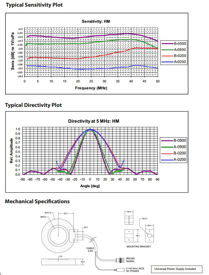
Hydrophone Handbook 0NDA Corporation 66 Specifications subject to change


0NDA Corporation DC Power Cable (2 m) Typical Directivity Plots (5 MHz)


Hydrophone Handbook 0NDA Corporation 68


0NDA Corporation


Hydrophone Handbook 0NDA Corporation 70


0NDA Corporation


Hydrophone Handbook 0NDA Corporation 72


0NDA Corporation


Hydrophone Handbook 0NDA Corporation 74


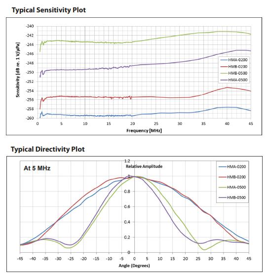
0NDA Corporation Typical Directivity Plots (5 MHz) Typical Sensitivity Plots


Hydrophone Handbook 0NDA Corporation 76

The HNA hydrophone has been successfully “stressed” under high intensity ultrasound fields. Details of the characterization can be found in "HIFU Transducer Characterization Using a Robust Needle Hydrophone", Proceedings of the International Society for Therapeutic Ultrasound, Oxford, UK, Aug. 29 Sept 2, 2006 found HERE.


Mechanical Specifications
0NDA Corporation Typical Sensitivity Plots Typical Directivity Plots (5 MHz)
Durability

Hydrophone Handbook 0NDA Corporation 78 200


0NDA Corporation

Hydrophone Handbook 0NDA Corporation 80 HCT Series, MCT 2000 HCT Series


0NDA Corporation


Hydrophone Handbook 0NDA Corporation 82 HCT Series, MCT 1200


0NDA Corporation


Hydrophone Handbook 0NDA Corporation 84


0NDA Corporation


Hydrophone Handbook 0NDA Corporation 86


0NDA Corporation

Hydrophone Handbook 0NDA Corporation 88


0NDA Corporation

2. Sample Hydrophone Connections Appendix Hydrophone Handbook 0NDA Corporation 90
2. Sample Hydrophone Connections 0NDA Corporation


3. OrderingAppendixInformation Hydrophone Handbook 0NDA Corporation 92
Hydrophones Corporation
“Gol Lipsden tick” HGL 0400 Capsule Hydrophone, 400 micron diameter nominal, includes 1 20 MHz EOC Calibration HGL 0200 Capsule Hydrophone, 200 micron diameter nominal, includes 1 20 MHz EOC Calibration HGL 0085 Capsule Hydrophone, 85 micron diameter nominal, includes 1 20 MHz EOC Calibration Needle HNA 0400 HIFU Hydrophone, 400 micron diameter nominal, includes 1 20 MHz EOC Calibration HNC 1000 High Sensitivity Needle Hydrophone, 1000 micron diameter nominal, includes 1 20 MHz EOC Calibration HNC 0400 High Sensitivity Needle Hydrophone, 400 micron diameter nominal, includes 1 20 MHz EOC Calibration
3. Ordering Information
Description
0NDA
HNP 0400 Broadband Needle Hydrophone, 400 micron diameter nominal, includes 1 20 MHz EOC Calibration HNP 0200 Broadband Needle Hydrophone 200 micron diameter nominal, includes 1 20 MHz EOC Calibration HNR 1000 Rugged Needle Hydrophone, 1.0 mm diameter nominal, includes 1 20 MHz EOC Calibration HNR 0500 Rugged Needle Hydrophone, 500 micron diameter nominal, includes 1 20 MHz EOC Calibration mbrMeane HMA 0200 Membrane Hydrophone, 200 micron diameter nominal, no backing, built in preamplifier and power supply, includes 1 20 MHz calibration. HMA 0500 Membrane Hydrophone, 500 micron diameter nominal, no backing, built in preamplifier and power supply, includes 1 20 MHz calibration. HMB 0200 Membrane Hydrophone, 200 micron diameter nominal, with backing, built in preamplifier and power supply, includes 1 20 MHz calibration. HMB 0500 Membrane Hydrophone, 500 micron diameter nominal, with backing, built in preamplifier and power supply, includes 1 20 MHz calibration
Item Number
Please contact us by submitting an online inquiry through the website: www.ondacorp.com. Alternatively, you can call Onda at 408 745 0383.
Preamplifiers AttenuatorMounts Hydrophone Handbook 0NDA Corporation 94
Hydrophones
Item Number Description ATH 2000 Hydrophone Attenuator, 20 dB at 2MHz, submersible, calibration included.
Item Number Description MHN Mount for HNR Hydrophone, compatible with 12.7mm rod MHGL Mount for HGL, HNA, HNC, HNP hydrophones, compatible with 12.7 mm rod.
Description AG 2010 Hydrophone Preamplifier for HGL Hydrophones, submersible, calibration included AH 2010 100 Hydrophone Preamplifier, 20 dB, 50 kHz 100 MHz, submersible, calibration included.
FiberOptic HFO 690 Fiber Optic Hydrophone, laser source 690nm, set of 5 fiber optic probes (2 meters in length each), fiber cleaver, fiber stripper tool, optical probe holder, self calibrating, deconvolution software, protective eyewear HFO 100 2 Set of 5 fiber optic cables (2 meters in length each) Cont.
Item Number
Ordering Information
AH 2020 100 Hydrophone Preamplifier, 0 or 20 dB, 50 kHz 100 MHz, submersible, calibration included
Ordering Information Item Number Description HC 0.03 1 Low Frequency Calibration 0.03 1.0 MHz (every 5 kHz) HC 0.25 1 Low Frequency Calibration 0.25 1.0 MHz (every 50 kHz) HC 1 20 Calibration 1 20 MHz (every 50 kHz) HC 20 40 High Frequency Calibration 20 40 MHz (every 2 MHz) HC 20 60 High Frequency Calibration 20 60 MHz (every 2 MHz) HC AMP 20 Calibration of any Onda AH/AG preamplifier at 20 dB gain setting HC AMP 0 20 Calibration of Onda AH/AG 2020 switchable preamplifier at both 0 dB and 20 dB gain settings HC G 0 Optional Calibration at 0 dB gain setting for dual gain amplifiers (AG/AH 2020) HC DIR Directivity at a single frequency between 5 15 MHz for one plane HC ATH Calibration of Onda ATH 2000 attenuator Calibrations Item Number Description AS NFAF BNC(F) SMA(F) Adapter AS NFNM 50 50 Ohm Terminator (BNC) AR AMAF Right Angle Adapter SMA(M) SMA(F) CA AMWNMN 100 Cable (RG174/U), 100 cm, SMA(M) BNC(M) CA AMWNMN 20 Cable (RG174/U), 20 cm, SMA(M) BNC(M) ships with HNA hydrophone Adapters and Cables 0NDA Corporation
Acoustically isolated sensor to provide localized measurements from 20 kHz to 1.2 MHz Chemical Compatibility: pH 4 12 (Teflon shaft, 27 cm)
Cavitation Measurement Instruments
MCT 2000 Acoustic Cavitation Meter: touch panel display, data logging, save parameters/spectrum/waveform, export data as text or MeasuredbinaryParameters: Fundamental Frequency (kHz), Direct Field Pressure (kPa), Stable Cavitation Pressure (kPa), Transient Cavitation Pressure (kPa)
HCT 0320 S Calibrated HCT 0320 Hydrophone
Item Number Description HCT 03202000MCT Calibrated HCT 0320 Hydrophone with MCT 2000 Acoustic CavitationAcousticallyMeterisolated
Probe Dimensions: Shaft Length: 270 mm, Shaft Diameter: 3 mm, Handle Length: 80 mm, Handle Diameter: 12 mm MCT 1200 Digital Pressure Meter: touch panel display, data logging, save parameters, export data, real time data transfer
Acoustically isolated sensor to provide localized measurements from 20 kHz to 1.2 MHz Chemical Compatibility: pH 4 12 (Teflon shaft, 27 cm)
HCT 03201200MCT
Ordering Information Hydrophone Handbook
HCT 0320 Hydrophone with MCT 1200 Digital Pressure Meter
sensor to provide localized measurements from 20 kHz to 1.2 MHz Chemical Compatibility: pH 4 12 (Teflon shaft, 27 cm)
Acoustic Calibration: calibration certificate included, traceable to National Physical Laboratory, stored in embedded memory
Probe Dimensions: Shaft Length: 270 mm, Shaft Diameter: 3 mm, Handle Length: 80 mm, Handle Diameter: 12 mm
0NDA Corporation 96
Probe Dimensions: Shaft Length: 270 mm, Shaft Diameter: 3 mm, Handle Length: 80 mm, Handle Diameter: 12 mm
Acoustic Calibration: calibration certificate included, traceable to National Physical Laboratory Includes MCT series connector with embedded acoustic calibration HCT CAL Acoustic Calibration: Calibration certificate included, traceable to National Physical Laboratory, stored in embedded memory.
Measured Parameters: Fundamental Frequency (kHz), Total Absolute Pressure (kPa, self calibration to absolute reference required)Selfcalibration function to match with test results from a reference meter in a User's cavitation vessel
4.AppendixResources 0NDA Corporation
2. Methodology for Onda's Hydrophone dfhttp://www.ondacorp.com/images/brochures/Onda_HydroCalMethod.pCalibrations:
4. Hydrophone Calibration Services: http://www.ondacorp.com/images/List_HydroCalibrations.pdf
Standards & Regulations:
Resources Hydrophone Handbook 0NDA Corporation 98
4. IEC 62359, Ed 2.0, 2010: Ultrasonics Field Characterization Test methods for the determination of thermal and mechanical indices related to medical diagnostic ultrasonic fields
1. AIUM/NEMA: Acoustic Output Measurement Standard for Diagnostic Ultrasound Equipment. American Institute of Ultrasound in Medicine, Revision 3. 14750 Sweitzer Lane, Suite 100, Laurel MD 20707 5906; National Electrical Manufacturers Association, 1300 North 17th Street, Suite 1847, Rosslyn VA 22209, 2004.
1. Converting from "EOC" Sensitivity to Amplifier loaded http://www.ondacorp.com/images/HydroCalConversion.pdfSensitivity:
3. IEC 61102 Measurement and characterisation of ultrasonic fields using hydrophones in the frequency range 0,5 MHz to 15 MHz.
8. IEC 60601 2 5, ed. 3.0: Medical electrical equipment Part 2 5: Particular requirements for the basic safety and essential performance of ultrasonic physiotherapy equipment
4.
6. IEC 61161, ed. 2.0: Ultrasonics Power Measurement Radiation force balances and performance requirements
3. Hydrophone Calibration tionnaire.pdfhttp://www.ondacorp.com/images/brochures/Onda_Hydrophone_QuesQuestionnaire:
2. IEC 60601 2 37, Ed. 2.0, 2007: Particular Requirements for the Safety of Ultrasonic Medical Diagnostic and Monitoring Equipment.
9. IEC 61689, ed. 2.0: Ultrasonics Physiotherapy systems Field specifications and methods of measurement in the frequency range 0.5 MHz to 5 MHz
Calibrations:
5. IEC 62127-1: Ultrasonics: Hydrophones: Part 1: Measurement and Characterization of Medical Ultrasonic Fields up to 40 MHz
7. US Federal Code of Regulations, Title 21 (Food and Drugs) Part 1050: Performance Standards for Sonic, Infrasonic, and Ultrasonic RadiationEmitting Products Section 1050.10: Ultrasonic Therapy Products
5. WarrantyAppendixPolicy 0NDA Corporation
Should your instrument prove defective during the limited warranty period, the corrective action will depend on the type of defect encountered. There are three primary types: (1) Software, (2) Hydrophones & Accessories, and (3) Instruments.
Thank you for trusting our products! Your measurement instrument is designed to put confidence in your ultrasound. To ensure your satisfaction, Onda is pleased to provide the warranty described below. Onda is committed to delivering the highest quality and service. If you have any questions, please contact us.
no other written or oral representations or warranties, express or implied, of fitness or merchantability concerning the goods sold hereunder.
Hydrophone Handbook 0NDA Corporation 100
Extended Warranty Options
What Onda Will Do to Correct Problems
A one (1) year extended warranty plan is available for purchase during the original one year limited warranty period, providing a total of two years of coverage. Onda may at its discretion allow the purchase of this plan after the one year warranty period subject to the conditions of the measurement instrument. Please contact Onda to learn more.
5. Warranty Policy
Our Warranty Onda products are warranted against defects in material and workmanship for a period of one (1) year from the date of delivery. During the warranty period, Onda will, at its option, repair or replace the product or any components that prove to be defective. Repairs are warranted for the remainder of the original warranty or a 90 day extended warranty, whichever is Therelonger.are
Build Release - updates to resolve defects Major Release – represents significant changes (e.g., StandardOS)Release includes new feature enhancementsProduct Name
Customers are entitled to build releases (highlighted in blue above) for the purchased software version at no charge throughout the life of the product. Major and standard releases are available for purchase.
Soniq Version 5 . 1 . 7
An example of Onda’s software version labeling is as follows:
0NDA Corporation
Hydrophones & Accessories: To resolve a hydrophone and/or preamplifier defect, the customer may send the items to Onda for a free evaluation. Items that are deemed defective due to problems with materials or workmanship will be repaired or replaced will be covered by Onda. Standard calibrations are replaced at no charge. Non standard calibrations will be replaced on a pro rated basis, based on the purchase date of the item. Items that are deemed defective due to damage caused by the end user after purchase will not be warranted. The inbound and outbound freight and related shipment charges including customs, taxes, tariffs, and insurance will be the responsibility of the customer.
Warranty Policy
Software: Onda will supply a fix, patch, or workaround for a software defect that prevents the customer from using the product as defined by the specification. The customer needs to report the defect in detail to Onda within the warranty period.
4. Any damage caused by third party items such as software, oscilloscopes, computer, or peripheral devices added to the product after shipment.
Instruments: For repairs of all other Onda products, the customer is responsible for freight and all related shipment charges both to and from Onda. If repairs are to be performed at the customer site, the customer is responsible for the cost of travel and accommodation for Onda personnel.
NOTE: All products returned for re calibration or repair must have a valid Return Materials Authorization (RMA) number issued prior to return and clearly marked on the return package. What This Warranty Does Not Cover The warranty does not cover:
1. Any part of a product that has been altered, repaired, or misused in any way that, in the opinion of Onda, would affect the reliability or detracts from the performance of the product.
Warranty Policy
3. Any labor involved in the removal and/or reinstallation of warranted equipment or parts on site.
Hydrophone Handbook 0NDA Corporation 102
Calibrations: For calibration of hydrophones, the customer is responsible for freight and all related shipment charges both to and from Onda. Onda ensures that all Onda hydrophones are calibrated in accordance with IEC 62127-2. Please refer to the Calibration section for further details.
5. Any damage from service performed by an individual other than authorized Onda Technical Service personnel.
2. Any damage or loss incurred in transportation of the product.
For products beyond the warranty period, please contact Onda to learn more about support options. Charges will vary depending on the nature of the problem.
Warranty Policy For Products Out of Warranty
Discontinuing Products
We realize that discontinuing a product can impact your organization and we strive to provide as much advance notice as possible. From the notification date for the discontinuance, a last time order opportunity will be offered that typically varies between 1 and 6 months depending on product type and parts availability. Purchases during this period will receive the guaranteed support as described by our standard warranty policy. Support beyond the warranty period will be on a best effort basis. Please note that we continuously review our support strategy and this policy is subject to change.
0NDA Corporation


