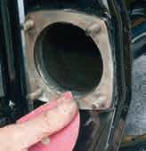
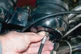
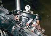
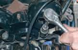
At the bottom of the main tube on the underside of the frame lies the oil filter. It was under a finned alloy plate secured by four 1⁄2in nuts. It should be a metal gauze mesh, but many bikes have had the original unit swapped out for a paper element filter, as fitted to the BSA B50. There was some debate about the wisdom of this modification, as it relied on the oil pump having to overcome more resistance in the delivery path to the engine, which was why most people opt for an external unit fitted on the return side.
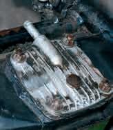
2.31 The oil filter unit sat at the bottom of the oil bearing spine of the frame under this plate.
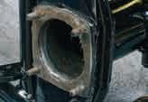
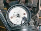
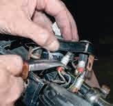
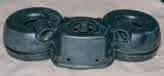
2.32 With the bottom plate removed, the filter unit was trapped between a pair of gaskets and, in this case, copious amounts of solidified silicone sealant –never a good sign.
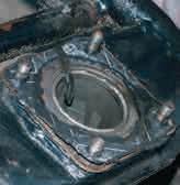
2.33 The filter itself was in good condition, as new, in fact. They often end up split or squashed.
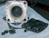
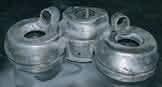
2.34 All the parts were thoroughly cleaned; there were new gaskets in the engine set I purchased, so it was ready to go back into the painted frame.
2.35 The mating surface on the frame was carefully cleaned and degreased. A thin smear of gasket sealant was then added, followed by the first gasket.
2.36 The side of the gasket facing the filter unit was then greased and the filter inserted. The bottom plate had its gasket sealed to the metal, but once again, I used grease where it met the filter unit, which would make future changes easier
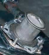
2.37 The cleaned and completed unit, bolted back up to the frame, ready to go.
CENTRE AND SIDE STANDS
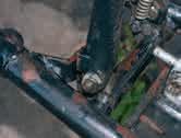
The centre stand was secured with two shouldered 9⁄16 bolts, which were held in place by a pair of 11⁄16 nuts, either self-locking like mine, or with tab washers on the earlier bikes. Removal was simple: I was able to hold the stand against spring pressure to get the bolts out. Once off, check that the bolt holes have not worn oval, or that the mounting lugs are bent. It is not unknown for the
2.38 The centre stand bolted on, although the design altered slightly during production.
Chapter 4
Brakes
Given the age of these motorcycles, a complete overhaul of the braking system would be a very good idea, unless the bike came with documentary evidence of recent work. Caution: Brake pads and shoes may contain asbestos, so make sure everything receives a good soaking in brake cleaner to damp down any possible dust before and during disassembly, then carefully bag the old parts before disposal. Spilled brake fluid may damage paint and plastic, so remove the tank first and cover the clocks, then take extreme care when removing components to avoid splashes. If the bleed nipple is free and the hydraulics working,
attach a rubber tube to it, and pump as much fluid out as possible, before starting any disassembly. Finally, the brakes are obviously a safety critical part of the rebuild, and the work is relatively straightforward, but do not attempt to overhaul them, if you feel in any way uncertain of your abilities. Brand new master cylinder assemblies, which are complete and ready to bolt in, are out there, as are the cylinders on their own, some in stainless steel.
The calipers and master cylinder assemblies are essentially much the same front and rear, so disassembly and repair are covered together. Some parts of the rebuild do not
strictly adhere to the Workshop Manual recommendations; the reasons for that are laid out, and the final decision on the best procedure rests with each individual.
MASTER CYLINDERS
Up to 1979, the front master cylinder was moulded into the front half of the switch unit wrapped around the bars. It was removed by undoing four crosshead screws to split the switchgear, although the screws are often corroded, so some releasing oil or an impact driver may be needed. After ’79, the cylinder was
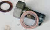
4.3 Union seals are copper. In theory, they can be annealed and reused, but check for signs of ridging due to over-tightening. If it is heavy, or you are in any doubt at all, just change them, which was what I did.
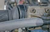
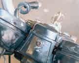
4.1 The front master cylinder will either have a pipe which fits directly into it, or a right-angled union under a rubber boot, like this one.
4.2 The assembly was held onto the switchgear by hex-headed bolts on my model.
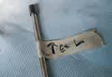
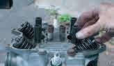
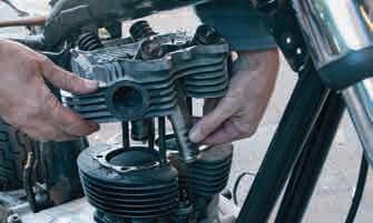
5.6 … before undoing them, though, I decided to remove and tag each pushrod in turn.
5.7
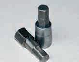
5.9 There is a tool sold for the bolts, although I had a suitable allen key socket already.
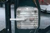
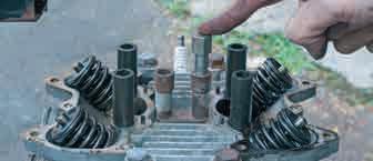
5.11 With the bolts out, the head was given a couple of gentle taps with a soft hammer, side-on to the finning to ensure no damage. This freed it without problem.
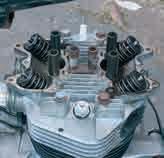
With the pushrods out of the way, the head bolts could come out.
5.8 A wiggle revealed that three of the four sleeved bolts were loose –not good.
5.10 The fit of the tool was good, despite its low price.
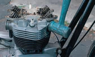
5.12 The head was lifted, but would not clear the studs, as the pushrod tubes were stuck to it. They took some persuasion to release their grip, but, once free, the head came away …
HOW TO RESTORE TRIUMPH BONNEVILLE T140
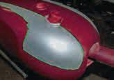
8.33 Factory colours changed with each model year, but the brochures did not always accurately reflect those changes. The 1979 publication showed a silver and candy red export model with gold stripes, which was the look I was now aiming for, although that combination was never put on sale that year.
CANDY
My bike’s paintwork was nonstandard black, and the American Title (log book/V5) did not have the original colour listed. In 1979, the factory churned out bikes for the USA in Candy Apple red and black, silver and black and, finally, blue and black. A glance at the brochure for that model year, though, clearly showed an export model with a red and silver tank. The pin striping was meant to be in black for that year’s models, although the red/black combo definitely carried gold pinstripes in the photo, so there were obviously some variations. I decided on red and silver, with gold striping, on the basis that Triumph must have done at least one like that, if only for the photo. Applying Candy was tricky, as it was almost translucent, and had to be
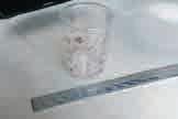
8.34 The paint needed to be carefully measured out in relation to its thinners. Plastic measuring cups are ideal, and provide a clean receptacle in which to mix it all, as well. The measuring stick next to the cup would have been another option.
built up with lots of coats. Coverage and gun pressure affected the final colour, so I decided that it was best to do all parts at the same time, to make sure everything got an equal amount.
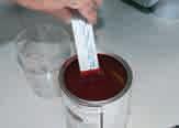
8.35 All the paint needed to be thoroughly mixed, as it tends to settle out in the can when stored. Filtering the mixed paint into the gun also helps prevent unwanted crusty contaminants getting in.
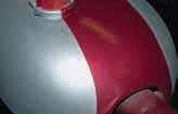
8.36 The chosen candy base coat was semi-translucent, and the colour only started to build up after many coats. I think I was up to around a dozen before I started to think the colour was getting there. Once happy, the masking tape was carefully removed whilst the paint was still slightly tacky. It was a great feeling, when the silver resurfaced.
8.37 The fine line tape left a clean sharp line between the colours, which would not have been possible with ordinary masking tape.
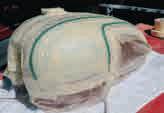
8.38 As my hands were not steady enough to attempt doing the pinstriping free style, it was back to more tape and masking, once the candy had dried. This time, I used a combination of tape and plastic masking sheet to cover up the areas to be protected.
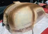
8.39 Gold base coat was then applied, and the tape removed, once again, before it had fully hardened, and still retained some flexibility.
LACQUER
This is what would give my bike its high gloss shine. Single pack lacquer would do the job, but can fade quickly; two-pack is far better, but you must get the non-isocyanate version, as mentioned above. It is thicker than its more dangerous cousin, and would require more postspraying work to get the best finish. Alternatively, I could have handed my panels over to a pro shop for this final critical stage.
8.40 The clear lacquer then went on, 1K in the gun as a home user, but an aerosol remained an option. I have used this one before for small parts and it gave a decent finish.
HOW TO RESTORE TRIUMPH BONNEVILLE T140
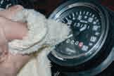
9.50 The speedo and tacho simply lifted out of their anti-vibration rubber mounts, once their respective cables were released.
9.54 The others were really tight and needed pliers to
9.55 The
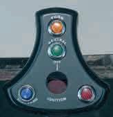
9.56 It received a new sticker, which wasn’t printed properly, as the ‘High Beam’ lettering was partially obscured, and ‘Oil’ was almost completely obliterated by the bezel. A new high beam warning light was needed, and, when it arrived, the lens wasn’t the same as the originals. Not important on my bike, maybe more so on a more meticulous restoration.
9.58
9.59
9.60 The last job with the clocks was to polish the lenses. If they had been badly hazed, I would have used very fine brazing paste to clean them.
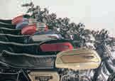
CHROME PARTS
This is another area where the rebuild budget could be put under considerable strain. Replacement is often the cheaper option, but as we have seen previously, the quality of aftermarket parts is often very poor, so it may be better to bite the bullet, and have the original stuff rechromed, if possible.
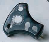
9.57 The alloy instrument panel was secured by two bolts passing through rubber sleeves.
9.51 The bulb holders pushed through a rubber grommet which secured them.
9.52 The switch and warning light panel was held in by screws into speed clips.
9.53 Once they were undone, it pulled up, with a couple of the warning light bulb holders left behind.
wiggle them loose.
The old surface was stripped, etched and painted like the switch panel.
It was chipped and sunbleached at the front.
bulb sleeves were pushed out, and the panel rubbed down and painted.