
Instruction Leaflet - Texas Pro - Issue 01 October 2025

Page 1


TEXAS PRO LED BATTEN LUMINAIRE INSTRUCTIONS

Issue 02 March 2026

Thank you for your purchase

For best results, have this light fitting installed by a qualified electrician, following these instructions. Keep this leaflet for future reference.

Safety

• Mains powered – installation must comply with building and electrical regulations.

• Always switch off and isolate the power before installation or maintenance.

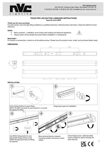
Need Help?

For advice or accessories, contact us at the address above. Please have the product name, model, and purchase details ready.

DIMENSIONS

INSTALLATION

Push endcap buttons to open fitting

Hinge body open for installation

Use BESA fixing points for your appropriate fixing method, push cables through back entry on fitting as required

Move terminal block to desired mounting location and secure mains cables

Close hinged cover. Optional safety screw provided to add to endcaps for extra security

NOTES / MAINTENANCE

1. This luminaire must be earthed.

2. For end conduit entry, drill appropriate size hole in defined position.

3. Luminaires fitted with electronic drivers are exempt from insulation resistance tests, as this may cause damage to the driver

4. Cleaning should be carried out at regular intervals so as not impair photometric performance or thermal safety of the luminaire

POWER ADJUSTMENT TABLE

*Disclaimer: For all drivers, only use the listed power settings, to avoid damaging the fitting*

These instructions should be followed in conjunction with the standard luminaire instructions. Please read carefully and pass to the end user/responsible person for retention and future reference.

INSTALLATION

1. Following the installation of the luminaire in accordance with the standard luminaire installation instructions, a separate permanent live supply should be terminated in the incoming supply terminal block in the luminaire, in the connection marked ‘L PERM’. The permanent supply MUST be taken from the same phase as the corresponding switched supply and MUST be wired at the switchboard so that upon instances of tests, it is isolated at the same time as the switched supply.

2. Once the permanent live supply is connected, connect the battery to the module via the ‘plug and mate’ connector, ensuring correct polarity is observed. Failure to observe correct battery polarity will result in permanent damage to the emergency module/driver.

3. N.B. to avoid potential damage to the battery please ensure the permanent live is energized as soon as possible following connection of the battery to the module.

4. Upon restoration of the power supply to the luminaire, check that the indicator LED fitted within the luminaire illuminates green. This indicates that the batteries are charging and that the charging circuit is healthy.

5. Allow the battery to charge for an uninterrupted period of not less than 24 hours prior to carrying out a full discharge test MAINTENANCE

6. The battery pack in this luminaire must be replaced when it is no longer able to satisfy its full rated duration.

7. In emergency mode the light level of the luminaire will be at a reduced output. Regular maintenance and gentle cleaning are recommended so as to ensure that the Emergency Output Factor (E.O.F) remains at specified levels.

8. Isolate the supply before servicing.

9. Please ensure that the emergency flux is not compromised at any time throughout the design life of the luminaire.

10. DO NOT INSULATION TEST

Caution:

The battery pack in this luminaire is a Lithium Iron Phosphate (LiFePO4) type which includes a dedicated protection circuit. If replacing the battery pack, the specification and chemistry must be identical to that detailed on the battery label.

TESTING OF EMERGENCY LUMINAIRES:

Recommended routine test procedures in line with BS 5266-1:2016 & BS EN 50172:2004.

For Self-test Versions see below:

Self-Test Operation: On connection of a permanent live supply, the unit will enter an automatic commissioning cycle as detailed in the table below. During this cycle, the permanent live supply should not be interrupted as this will result in the charging timer resetting to zero and restarting the commissioning process. Following successful completion of the commissioning cycle, in line with BS EN 62034 and BS EN 50172:2004, the unit will perform a 30 second function test automatically at monthly intervals for 11 months, and in the 12th month, a full rated duration test will be performed.

LED Status Indicator during commissioning:

LED Indication

Stage / Period

Green Permanently On 1 – 24h

Green Slow Flash (2s on / 2s off) 2 – Rated Duration

Green Slow Flash (4s on / 1s off) 3 – 24h

Green Permanently On 4 – Normal Operation

LED Status Indicator following commissioning:

LED Indication Status

Green Permanently On

Green Slow Flash (2s on / 2s off)

Green Slow Flash (4s on / 1s off)

Red Fast Flash (0.5s on / 0.5s off)

Notes on Fault Code:

Status

Initial Battery Charge

Duration Test

Battery Recharge and test passed

Commissioning Complete

Normal, Commissioned, Standby Mode

Function Or Duration Self-Test in Progress

Battery Recharge (24h Following Duration Test) and test passed

Battery Disconnected, Battery Duration Fault, Lamp Fault

The unit monitors health/status in both standby (charging), and self-test modes. If the battery is disconnected in standby mode, the LED indicator will ‘fast flash red’, as in the table above. On re-connection of the battery, the LED indicator will revert to green. If the unit detects a fault to either the battery or lamp head during a test, it will ‘fast flash red’, and remain in this status until the fault is fixed and the unit has completed a further successful test.

Note: In order to maintain compliance of the self-test system, the unit is factory set to undertake tests randomly. Because of this, tests may occur at any time in the 30-day interval period. Caution should be exercised where this may be inconvenient, or cause disturbance, such as in hospitals, nursing homes and other premises with sleeping accommodation

Fitting Size

4ft LOW OUTPUT

Current

Dip Switch Pin 1 Pin 2 Pin 3

200mA OFF ON ON

250mA ON OFF OFF

300mA ON OFF ON

350mA ON ON OFF

4ft HIGH OUTPUT 200mA OFF OFF ON

250mA OFF ON OFF

300mA OFF ON ON

350mA ON OFF OFF

5ft LOW OUTPUT

200mA OFF OFF ON

250mA OFF ON OFF

300mA OFF ON ON

350mA ON OFF OFF

5ft HIGH OUTPUT 200mA OFF OFF OFF

250mA OFF OFF ON

300mA OFF ON OFF

350mA OFF ON ON

6ft LOW OUTPUT

200mA OFF OFF ON

250mA OFF ON OFF

300mA OFF ON ON

350mA ON OFF OFF

6ft HIGH OUTPUT

200mA OFF OFF OFF

TYPE OF DIMMING

This product uses a LED driver that is capable of 2 methods of dimming:

Dimming via a Digital Addressable Lighting Interface

Note! Further input may be required from your lighting controls provider.

REMOTE DRIVER WIRING

Dimming via a retractive switch

Note! Different makes of control gear should never be actuated by the same retractive switch in an installation. There is a risk of a conflict in what you are asking the ballast to do.

Power supply & signal wires input for luminaires with remote mounted LED drivers (i.e. driver not inside luminaire)

Note! The make of LED driver will need to be identified so the correct wiring can be followed.

INTERNAL DRIVER WIRING

Note: LSD = Switch Dim Live

Power supply & signal wires input for luminaires with built in LED driver & where there is a terminal block present

Note: LSD = Switch Dim Live

Turn static files into dynamic content formats.

Create a flipbook