

EUH
ELECTRIC UNIT HEATER

INSTALLATION, COMMISSIONING AND SERVICING MANUAL


These appliances meet the following directives:
The Eco design for Energy-Related Products and Energy Information (Amendment) (EU Exit) Regulations 2020
Electromagnetic Compatibility Regulations 2016
Electrical Equipment (Safety) Regulations 2016
Supply of Machinery (Safety) Regulations 2008
Supply of Machinery (Safety) Regulations (A) 2011
Please read this document carefully before commencing installation, commissioning and/or servicing. Leave it with the end user/site agent to be placed in their premises technical file after installation.
WARNING
Improper installation, adjustment, alteration, service or maintenance can cause property damage, injury or death.
All work must be carried out by appropriately qualified persons.
The manufacturer does not take any responsibility in the event of non-observance of the regulations concerning the connection of the apparatus causing a dangerous operation possibly resulting in damage to the apparatus and/or environment in which the unit is installed.

MANUAL PART NO. D301600 ISS 0
Contents General Information (G) EUH range ................................................. 4 Using this manual 4 Warranty 4 Important notice to installers 5 Health and safety 6 Uncrating / preparation ............................... 7 Technical Data (TD) Technical data 8 Dimensions ................................................. 8 Clearance distances 8 Signal pro display panel dimensions 9 Installation (I) Heater location ........................................... 10 Mounting the heater 10 Electrical supply 11 Thermostat controls 11 Signal Pro display panel 12 Wiring connections 13 Operation and Controls (C) Introduction 14 Networking 14 Heater addressing 14 Keypad buttons .......................................... 15 Set language 15 Installer initial setup / engineers mode 15 User mode 15 Diagnostic display 16 Normal operation 16 Features ...................................................... 16 Configuration program key 17 Fan speeds 17 Temperature sensors 13 Thermostat input ........................................ 13 Timer / BMS input 17 Door / off input 18 Network data format 18 Data protocol 18 Native data format 18 Modbus data format ................................... 18 Modbus function codes 19 Modbus function arguments 19 Modbus function arguments, coils / inputs 20 Maintenance and Servicing (MS) Maintenance 21 Fault Finding (FF) General 22 Display panel. ............................................. 22 Fault finding chart 23 Spare Parts (SP) Spare parts. ................................................ 24
G
EUH Range
General product information
The EUH range is the latest generation of electric unit heaters, UKCA certified to BS EN 60335-1 and -2 for use in non domestic installations.
There are four models in the range with heating duties of 10, 20, 30 and 40kW respectively. All models have been designed for a three phase electrical supply. Details of the unit duty and electrical supply requirement are given on the heater rating plate. Check the rating plate to determine if the heater is appropriate for the intended installation.
This installation manual is shipped with the unit. Verify that the literature is correct for the model being installed. If the manual is incorrect for the heater, contact the supplier before beginning installation.
The instructions in this manual apply only to the models listed.
Installation should be carried out by a suitably qualified installer in accordance with these instructions and the current rules and regulations in force. The installer is responsible for the safe installation of the heater.
Using this manual
The symbols for ‘Caution’ and ‘Warning’ are used to highlight certain points throughout this manual.

Caution is used when failure to follow or implement the instruction(s) can lead to premature failure or damage to the heater or its component parts.

Warning is used when failure to heed or implement the instruction(s) can lead to not only component damage, but also to a hazardous situation being created where there is a risk of personal injury.
Warranty
This equipment comes as standard with a manufacturers two year warranty (2 years parts, 1 year labour) unless agreed otherwise at the time of order. The warranty is void if:
1. The installation is not in accordance with these instructions.
2. Wiring is not in accordance with the diagram furnished with the heater.
3. The unit is installed without proper clearances wherever clearances are required regardless of the material being combustible.
4. The unit is installed without proper ventilation.
5. The equipment is used in atmospheres containing flammable vapours or chlorinated or halogenated hydrocarbons or any contaminant (silicon, aluminium oxide, etc.).
6. The unit has not been serviced and maintained in accordance with the information contained within these instructions.
7. An appliance is connected to a duct system or the air delivery system is modified in any way.
Ignoring the warning and caution notices and the advice from the manufacturer on installation, commissioning, servicing or use, will jeopardise any applicable warranty. This could also compromise the safe and efficient running of the appliance itself and thereby constitute a hazard. The electrical isolator should only be used for maintenance purposes or in an emergency.
Page No 4 of 28 Reznor, EUH, Installation Manual, EN 2024-02, D301600 Iss 0
Important notice to installers
Before installation, carefully read these instructions and follow the processes explained by the manufacturer. These instructions are only valid for appliances designed to operate in Europe. If the country code on the appliance data label does not match the country of installation or the country codes as shown in this instruction manual, it will be necessary to contact the distributor or manufacturer to provide the necessary information for the modification of the appliance to the conditions of use for the country of installation.
Installing, commissioning, testing, programming and maintenance of these products must only be carried out by suitably qualified and trained technicians and in full compliance with all applicable regulations and current best practices.
Check if the appliance as described on the packaging label is in accordance with the correct type and model as specified on the data plate and complies with your customer order.
Check that the temperature ranges given and those of the location match. The appliance must be powered with a voltage corresponding to the value shown on the rating plate.
These units must be installed in accordance with the rules in force and local regulations / legislation as appropriate plus all local building codes. Installers should satisfy themselves that the gas pipework installation is carried out in accordance with all current legislation, Codes of Practice and recommendations.
Improper installation, adjustment, alteration, service, or maintenance can cause property damage, injury, or death. Read the installation, operation, and maintenance instructions thoroughly before installing or servicing this equipment.
These appliances are not designed for use in hazardous atmospheres containing flammable vapours or combustible dust, in atmospheres containing chlorinated or halogenated hydrocarbons or in applications with airborne silicone substances.
Any reference made to Laws, Standards, Directives, Codes of Practice or other recommendations governing the application and installation of heating appliances and which may be referred to in Brochures, Specifications, Quotations, and Installation, Operation and Maintenance manuals is done so for information and guidance purposes only and should only be considered valid at the time of the publication.
The manufacturer cannot be held responsible from any matters arising from the revision to or introduction of new Laws, Standards, Directives, Codes of Practice or other recommendations.
Reznor, EUH, Installation Manual, EN 2024-02, D301600 Iss 0 Page No 5 of 28
G
Health and safety
Ensure that anchoring points are suitable for the weight and loading of the product and if required, add suitable reinforcement to the anchoring points area.
Due consideration should be taken for workplace safety, risk assessments and waste disposal.
Any modification of the product may be hazardous and the manufacturer is not liable for any damage or injury caused by improper use.
Do not use this appliance if any part has been immersed in water. Immediately call a qualified service technician to inspect the appliance and replace any control that has been immersed in water.
This appliance is not intended for use by persons (including children) with reduced sensory or mental capabilities or lack of experience and knowledge, unless they have been given supervision or instruction concerning use of the appliance by a person responsible for their safety. Children should be supervised to ensure that they do not play with the appliance.
This manual should be kept in a safe place for future reference.
Do not use the heater in areas where there is an explosion risk or where there are inflammable gases such as ammonia, paint thinners or glue.
Do not store or use petrol or other flammable vapours and liquids in the vicinity of the appliance. Do not place inflammable objects in front of the heater outlet.
Do not cover the heater. Ensure the air inlet and outlet are not obstructed.
Improper installation, adjustment, alteration, service or maintenance can cause property damage, injury or death.
Read the installation, operation and maintenance instructions thoroughly before installing or servicing this equipment.
Installation, assembly, commissioning, service and maintenance procedures must be carried out only by suitably competent qualified persons.
Unauthorised modifications to the appliance, or departure from the manufacturer’s guidance on intended use, or installation contrary to the manufacturer’s recommendations may constitute a hazard.
Use only factory authorised parts and spares when replacement is required.
In case of persistent problems, contact your distributor.
Page No 6 of 28 Reznor, EUH, Installation Manual, EN 2024-02, D301600 Iss 0 G
Uncrating / preparation
Prior to crating and shipping, this unit was test operated and inspected at the factory and left in full operating condition. If the unit has incurred damage in shipment, document the damage with the transport company and contact your supplier.
After unpacking the appliance leave it fastened to the wooden blocks / pallet until just before siting to prevent damage to the unit.
Read this booklet and become familiar with the installation requirements of your unit.
Check if the local electricity supply is compatible with the data plate.
The appliance must be installed in accordance with the current rules in force and any local or national regulations.
The requirements of the "Local Building Standards office", the premises "Insurance" undertaking and the "Fire Office" must also be observed.
Before commencing installation, ensure all necessary supplies, tools and manpower are available.
Reznor, EUH, Installation Manual, EN 2024-02, D301600 Iss 0 Page No 7 of 28 G
Technical Data
TD
Heating
Airflow
Airflow
Throw
Clearances
Note that these are "guestimates". Actual figures are to be provided


Page No 8 of 28 Reznor, EUH, Installation Manual, EN 2024-02, D301600 Iss 0
Model Unit EHU10 EUH20 EHU30 EUH40 Diameter mm Length mm Total width inc bracket mm Total height inc bracket mm Weight kG
Dimensions Model Unit EHU10 EUH20 EHU30 EUH40 Heating Duty Max kW 10 20 30 40
Duty Min kW
Max m3/h
Min m3/h
Max m Electrical Supply V/ph/hz 400V / 3Ph / 50Hz Protection IP Motor Data Power W Voltage V Current A Noise dB(A) Model Unit EHU10 EUH20 EHU30 EUH40 Front mm 5000 5000 5000 5000 Rear mm 300 300 300 300 Side mm 300 300 300 300 Access Panel mm ??? ??? ??? ???
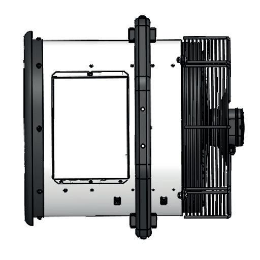
Front view
Side view
Top view
Signal Pro display panel dimensions
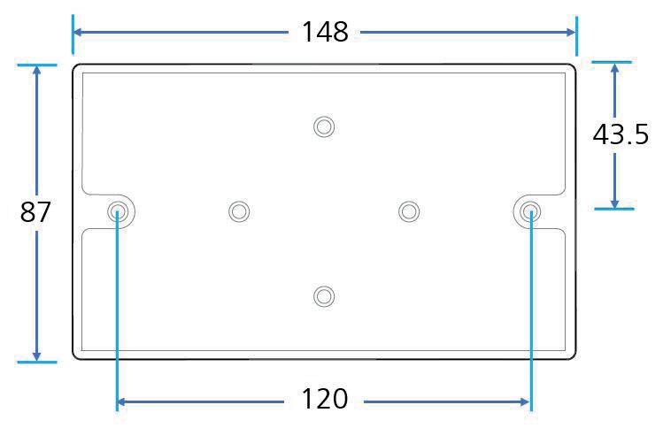
The Signal Pro display panel is supplied with an industry standard plastic double surface mounted socket box. Alternatively, the display panel can be flush mounted using a customer supplied metal flush conduit box as shown in Figure 5.2


Reznor, EUH, Installation Manual, EN 2024-02, D301600 Iss 0 Page No 9 of 28 TD
Figure 1 Surface mount box
Figure 1.2 Surface mounting back box dimensions
Figure 1.1 Flush mounting plastic conduit box (by others)
Installation
Heater location
The heater casing and other accessible surfaces will be very hot under normal operation and will cause burns if touched. Suspend the heater such that these components cannot be touched.
This air heater must be installed and maintained in accordance with this manual, national and local building regulations and local health and safety regulations
Do not use the air heater in a very dusty environment. Dust may accumulate and cause a defect of the heater. This is also the case for the room thermostat.
For best results, the heater should be located with certain rules in mind:-
• Always ensure that the minimum clearances detailed previously are maintained.
• When possible, heaters should be arranged to blow toward or along exposed wall surfaces.
• Suspended heaters are most effective when located as close to the working zone as possible, but care should be exercised to avoid directing the discharged air directly on to room occupants.
• Partitions, columns, counters or other obstructions should be taken into consideration when locating the unit heater so that a minimum quantity of airflow will be deflected by such obstacles.
• When unit heaters are located in the centre of the space to be heated, the air should be discharged toward outside / external walls.
• In large areas, unit heaters should be located to discharge air along exposed walls with extra units provided to discharge air in toward the centre of the area. For optimum results heaters are best used in conjunction with recirculating air fans suspended at high level. Contact the manufacturer / distributor for more details.
• At those points where infiltration of cold air is excessive, such as at entrance doors and roller doors, it is desirable to locate the unit so that it will discharge directly toward the source of cold air, typically from a distance of 4.5 to 6.0 metres. Alternatively, air curtains can be installed. Contact the manufacturer / distributor for more details.
Hanging the heater
Dnot locate the heater where it may be exposed to water or where the ambient temperature exceeds 40°C.
Ensure that the structural elements, which will be used to suspend or support the appliance, are adequate to carry the weight of the appliance. Unit weights are given in the technical data section previously.
Sufficient space must be provided around the heater for servicing and clearances for safety.
Ensure that the unit heater is installed in a level plane.
Always provide a minimum clearance of 600mm at an open air intake (inlet side)
Suspend the heater only from the mounting bracket provided with the heater.
Do not add additional weight to the mounted heater.
The minimum safe mounting height is 2.5 metres.
Ensure the air flow to and from the heater is free of obstacles.
Ensure there is at least 5 metres clear from obstruction in front of the heater.
Page No 10 of 28 Reznor, EUH, Installation Manual, EN 2024-02, D301600 Iss 0
I
Electrical supply.

The electrical installation may only be carried out by an appropriately qualified person in accordance with the current Rules and Regulations in force.
This appliance must be earthed.
Due to the heater having “Fan Over Run” circuitry the heater must not be turned ON and OFF using the mains supply isolator. The mains supply isolator should only be used in an emergency or if you need to turn off the heater (once cooled down) for long periods.
For safety reasons, a sound earth connection must always be made to the unit before it is put in to use. The unit should be wired in accordance with IEE Regulations for the Electrical Equipment of Buildings.
The display panel is connected to the control panel (base unit) via a prewired RJ45 cable maximum length of 100m. (10m supplied as standard). It is recommended that this cable is run separately within its own trunking to avoid electrical interference.
Units require a connection to a 3 phase 400V and neutral power supply. The models consume 10kW, 20kW, 30kW and 40kW respectively at 415 Volts when switched to the full heat position depending on the model and capacity setting. Check that the electrical specification is in accordance with the specified data on the air heater.
The appliance MUST be connected to the supply via a switched fused isolator, appropriately sized to suit the total electrical load and having a contact separation of greater than 3mm. See technical data for fuse rating on page <?>.
Check that the air heater is well earthed and that an earth leakage test is carried out.
All electrical connections must be made in the heater control compartment on top of the heater. Once the cover has been removed, the installation engineers terminal block is located to the right hand side of the unit. This terminal block is used for the connection of the mains supply and additional controls, for example an external thermostat. Wiring must be carried out in accordance with the unit wiring diagram given on page <?>.
The minimum external control required for the unit is a room thermostat capable of providing a 0-10V DC signal to the burner. It is essential that the main input line and neutral to terminals L and N remain live at all times even when the unit is switched off to ensure correct operation of the unit and to let the fan operate independent of the heating control. Never incorporate controls that isolate the appliance electrically.
Thermostat controls
Ancillary controls are required to provide timed heat cycles, room comfort temperature level, frost protection, override air circulation etc. These are not included with the appliance and should be ordered separately.
Do not attempt to control more than one unit heater from a single thermostat or control panel unless a properly wired relay is fitted. Follow the instructions supplied with such panels.
The location of the room thermostat or sensor is very important. It should not be positioned on a cold wall or cold surface. Avoid location in draughty areas or where it may be influenced by heat sources e.g. the sun, process plant, etc. The thermostat should be mounted on a vibration free surface and mounted about 1.5 metres above floor level. Follow the thermostat manufacturers instructions. The thermostat must be suitable for potential free contacts.
Reznor, EUH, Installation Manual, EN 2024-02, D301600 Iss 0 Page No 11 of 28 I
ISignal Pro display panel
The display panel can be installed using the standard double surface box supplied or recessed using a suitable flush mounted double conduit box. see “Figure 5.2 Surface mounting back box dimensions” on page <?> for details.
The display panel can be connected up to a maximum of 16 unit heaters in one network.
For mains wiring refer to the wiring diagram relating to the model being used see “Wiring diagrams.” on pages <?> to <?>.
The display panel is connected to the base unit in the heater via a pre-wired RJ45 cable/plug. These cables are available in 2, 10, 20, 30, 50 and 100m lengths. It is recommended that this control cable is run separately within its own trunking to avoid external interference.
Maximum cable run in any network must not exceed 100m in total including display panel cable.
Note: All heaters connected within the network system will operate under the settings of the single display panel. See “Installer initial setup” on page 24 to register all heaters in the network with the display panel. Any heater within the network can be connected with and respond to the following optional circuits:
• External switch (i.e. BMS enable) where required, to be volt free and wired in PARALLEL via normally open contacts to each terminal pair ‘TIMER’. (Contacts closed to enable). Only heaters wired this way will respond to the enable signal.
• Door switches where required, to be volt free and wired to INDIVIDUAL base units via normally closed contacts to each terminal pair ‘DOOR’. (Contacts open to enable door mode). Only heaters wired this way will respond to the door mode.
• An external sensor, where required, can be wired to INDIVIDUAL base units to each terminal pair ‘EXT’. Only heaters wired this way will respond to the sensor setting.
Page No 12 of 28 Reznor, EUH, Installation Manual, EN 2024-02, D301600 Iss 0
Figure xx display panel
1a to 6a Capacity jumpers see page <?>
Protection
There are two high speed fuses on the base unit to protect the switching thyristors for the heater. An external circuit breaker with the appropriate rating should be installed for the protection of the installation
continued
Reznor, EUH, Installation Manual, EN 2024-02, D301600 Iss 0 Page No 13 of 28 I
415v 50Hz MAINS SUPPLY RJ45 Cable Programmer Keypad External Switch (BMS) Door Switch External Temp Sensor J1 Factory Connections Installer Wiring
- Installer Connections PE N L3 L2 L1 6A 5A 4A 3A 2A 1A 6 5 4 3 2 1 6 5 4 3 2 1 Double Deck Terminals J2 Heat Capacity Jumpers E1, E2 and E3
Wiring Connections
900724 Guardian Signal Pro Series Electric
Terminal Description Cable PE Mains earth 10mm² N Neutral L1 Phase 1 L2 Phase 2 L3 Phase 3
Figure xx Wiring diagram electric heated
Table 7 Cable specification electric heated
Terminal Description Cable 3 & 4 Optional external switch 1.5mm² 5 & 6 Optional door contact 1 & 2 Optional external sensor PCB Fuses Rating (A) F1 T1H (slow blow) F2 & F3 400v
Table 7.1 Cable specification electric heated
Operation and controller
Introduction
The function of the EUH Control is to control the unit heater and fan to maintain a set air outlet temperature as measured by a temperature sensor.
The outlet set point, fan speed (normal / boost) and heat on signal is sent from the display panel to the EUH control via an RS485 communication interface. The EUH control returns data to the panel via the same communication interface.
Up to 16 EUH controls can be present on the RS485 so each has an address set via a 4-way DIP switch. The EUH control is a slave on the network and only transmits in response to a message from the panel which is the master.
Temperature sensors provide feedback on the heater output, monitor the PCB temperature for overheat and provide the panel with room temperature readings.
The configuration program key sets the type of heater and rating.
There are additional external inputs to the control which adjust the control behaviour: Timer switch, Door switch and Thermostat input.
The heater output is a PWM signal using a PID control.
The fan speed control is by 0 ~ 10V output.
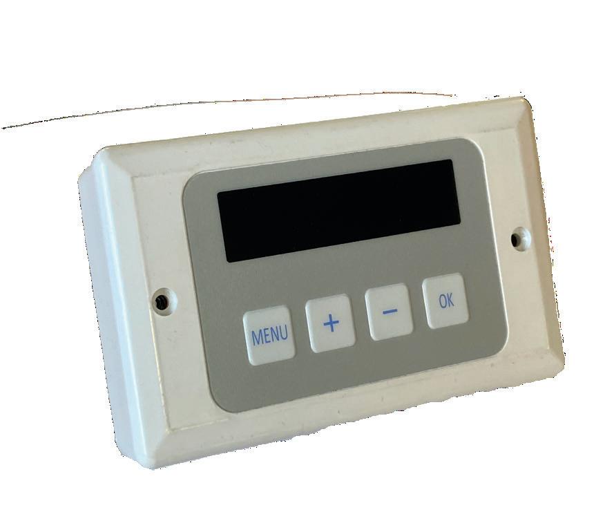
The display panel has a microcontroller, a 16 character by 2 line display, 4 buttons and a communication interface. It also has a clock with battery back-up to provide time based control functionality. The display panel can be set to operate with different languages at the time of installation.
Networking
The display panel is connected to the first heater via pre-wired RJ45 cable to the socket in the first heater housing. See figure xx on page <?>.
Connect a second RJ45 cable in to the spare RJ45 socket of the first heater, and then take across to one of the RJ45 sockets in the second heater.
Further RJ45 cables can be used to connect more heaters to the network; up to a maximum of 16 heaters can be linked to one display panel.
The RJ45 cable is 10m as standard however it is available in 2m, 20m, 30m, 50m and 100m lengths.
Maximum length 100m. (Total length of cable used between display panel and last heater in network).
It is recommended that this control cable is run separately within its' own trunking if possible, to avoid external interference.
Note: All heaters connected within the network system can be controlled under the user settings of the single display panel. See “Installer initial setup” on page <?> to register all heaters in the network with the display panel.
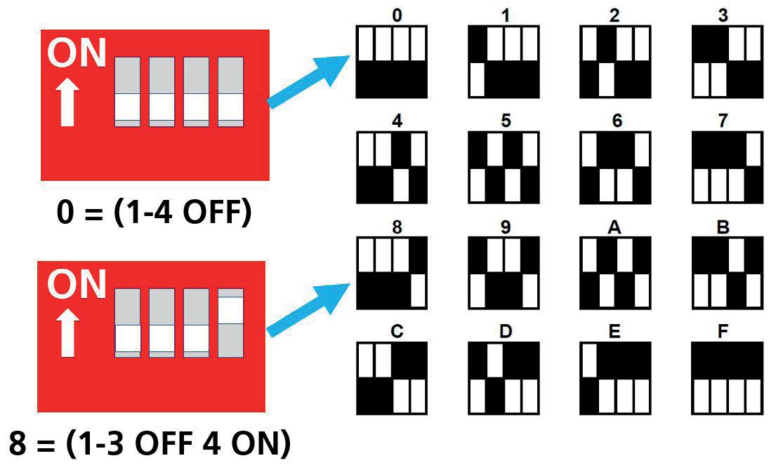
Heater addressing
All heaters work on an address to communicate with the display panel and are supplied with an default address of ‘0’.
Where multiple heaters exist in a network they must be re-addressed using a unique address (0-9/A-F). This is achieved using the 4 way DIP switch [2] mounted on the control panel base unit PCB.

The display panel will check all addresses on first power up and the result will be displayed. All addresses will be viewed in rotation.
Page No 14 of 28 Reznor, EUH, Installation Manual, EN 2024-02, D301600 Iss 0 C
Figure xx DIP switch position
Figure xx DIP switch setting
Note: If any address is altered after initial power up or a heater is removed after initial installation, the display panel will also retain the original address although unable to respond. To remove an unwanted address, rescan the whole network in the manner detailed in Engineers instructions (page <?>.
Keypad buttons
The buttons have the following functions:-


• MENU enters the programming menu and advances item to program in order below.
• OK starts programming of visible item, value flashes during programming.
• PLUS and MINUS adjust the value.
• OK saves the modified value or MENU stops programming with value reverting to old value.
If more than one heater is connected to the network then for some settings all controls can be set together or controls can be set individually. Only controls that are present on the system can be programmed, others are skipped over. Heaters are addressed as 0 to 15 by the display, corresponding to bit switch settings 0 to F on the heater control.
Set language
On first start up, the control panel will ask for a language to be set. The options are En - English, Fr - French, Es - Spanish, Nl - Netherlands and Pl - Polish
Installer initial setup / Engineers mode
Press and hold '+' and then press MENU to enter Engineers Mode.
1. Enter PIN, if enabled in Engineers.
2. Set Internal or External Timer operation, system wide, overrides time prog.
3. Enable Night operation, system wide.
4. Enable Frost operation, system wide, fixed 5°C.
5. Set Outlet Temperature, per heater, range 30 ~ 50°C, default 40°C.
6. Set Fan Speed, per heater, 1 or 2 = normal or boost.
7. Set Bandwidth, system wide, range 2 ~ 10°C, default 2°C. See fig 1.Set Bandwidth
Taper, range 2 ~ 20°C, default 5°C. Set Deadband, system wide, range 2 ~ 10°C, default 2°C.
8. Set sensor offset, per heater with room sensor, range -5 ~ +5°C.
9. Set Overtime maximum, system wide, range 0 ~ 10 hours, default 1 hour.
10. Set Fan Only maximum, system wide, range 0 ~ 10 hours, default 1 hour.
11. Set Optimum Start time, system wide, range 0 ~ 240 mins, default 60 mins.
12. Set Optimum Stop time, system wide, range 0 ~ 120 mins, default 30 mins.
13. Display hours run per heater.
14. Set Language. En, Fr, Es, Nl, Pl. New messages not implemented in languages other than En.
15. Heater address scan.
16. Factory Reset.
17. PIN protection, On/Off.
18. Set PIN.
19. Engineer Menu end.
User mode
Press MENU button to enter User Mode.
1. Check temps. Displays average room temp, set day temp, set night temp. No PIN entry is required to display these temperatures.
2. Enter PIN, if enabled in Engineers
3. Set Overtime operation. Short term On operation, maximum set in Engineers.
4. Set Fan Only Overtime operation. Short term operation, maximum set in Engineers.
5. Set Holiday operation. Medium term Off/ Frost only operation.
6. Set Mode: Auto, Off Mode, Heat Only, Fan Only.
7. Set Clock, time and day.
8. Set Program, 3 On, 3 Off times.
9. Set Temperatures. On (day) temp, Off (night) temp.
10. Menu end.
Reznor, EUH, Installation Manual, EN 2024-02, D301600 Iss 0 Page No 15 of 28 C
Diagnostic display
Press and hold '+' and '-' then press MENU to enter diagnostic mode. A display of the following is given per heater:-
1. Heater ID, 0 to 15
2. Config, ‘C’: 0 error, 1-4 is 10 to 40kW, ‘d’ is development.
3. Heat, ‘H’: 0/1 is on/off.
4. Fan, ‘F’: 0/1 is on/off.
5. Heating element output power: xxx%.
6. Room temperature, if sensor fitted, Rttt = tt.t°C, ‘xxx’ sensor out of range, ‘---' no sensor fitted.
7. Outlet air temperature, Ttt = tt°C, ‘xx’ sensor out of range.
8. PCB temperature, Ptt = tt°C, ‘xx’ sensor out of range.
9. Limit Stat open circuit, ‘S’ = open circuit (fault, heat off).
10. External door input, ‘D’ = open circuit (door open).
11. External input, ‘T’ = open circuit (timer off).
Normal operation
Under normal operation, the panel will display an address scan every time the panel starts. Once the address scan has been displayed, the panel will show on an alternating basis:-
• Panel status:
- day and time
- on / off period
- room temperature (average of connected sensors)
- an error message if the battery is low
• Heater status (per networked heater):
- Heater number: 0 ~ 15.
- Outlet temperature, °C.
- Heater status: Outlet temp, ON/OFF, Door Open, Timer Off, Stat Temp Error, - Comms Error.
- Heater mode: ON/OFF
Features
The controller provides the following features:-
• Auto mode: fully automatic control of heating and fan-only to time program using On (day) temp and Off (night) temp. In On periods heat and fan-only. In Off periods heat only.
• Off mode: only heats if below 5°C. If Frost is disabled, in Engineers settings, then absolutely no heating.
• Heat Only: automatic control of heating to time program using On (day) temp and Off (night) temp.
• Fan Only: automatic control of fan-only (no heat) to time program using On (day) temperature. No fan-only in Off periods.
• Overtime: heats to On (day) temperature, no fan-only, for the number of hours and minutes set. If overtime is set then if Menu is pressed the overtime is cleared immediately.
• Fan Only Overtime : runs fan-only to On (day) temperature, no heating, for the number of hours and minutes set. If fan-only overtime is set then if Menu is pressed the fan-only overtime is cleared immediately.
• Optimum Start: starts heating before an upcoming On period, time depends on temperature raise to Day Temp, historical heat-up times and Optimum Start maximum time set in Engineers (default 60 minutes).
• Optimum Stop: stops heating before an upcoming Off period, time depends on historical cool-down times and Optimum Stop maximum time set in Engineers (default 30 minutes). Control will not allow the temperature to drop more than 2°C in this period.
• Holiday: When holiday is set the system operates with Off mode for the number of days set. Holiday starts at midnight on the day it is programmed and counts down one day every midnight thereafter. If holiday is set then if Menu is pressed the holiday is cleared immediately.
Page No 16 of 28 Reznor, EUH, Installation Manual, EN 2024-02, D301600 Iss 0 C
• Hysteresis on setpoint is +0.5°C, i.e. heat to Set Point + 0.5°C then cool to Set Point.
• Under Engineers the timer mode can be set to external/BMS where the control will ignore the time program and control to On/ Day temperature when Timer input is closed and Off/Night settings when the Timer input is open. All controls on the network will be controlled from one Timer input. Usually only one heater will have a Timer input, other heaters should be left with the input opencircuit as the panel will respond if any of the Timer inputs is closed-circuit.
• Room Sensor: If no room sensor is present on the system the heaters will be off and panel will display an error message. If one room sensor is present on the system then that will be used for all heaters. If more than one room sensor is fitted, multiple heaters only, then Signal Pro averages these sensors.
Configuration program key
A program key has been provided for the unit heater to set the type and rating of the control, and the normal / boost fan speeds. The chart below details the various keys.
Key Application
No Key Control will not run. Error signal at panel
22k Ohm 10kW heater
15k Ohm 20kW heater
10k Ohm 30kW heater
6.8k Ohm 40kW heater
Fan Speeds
Pre-programmed fan speed outputs are:-
Temperature sensors
Three separate temperature sensors have been provided at the unit heater:-
• Air outlet temperature - Thermistor bead on 1m orange wires. Measurement range 0°C to 100°C. Used by the controller as feedback to adjust heat level to achieve desired outlet air temperature.
• Room temperature - Thermistor bead inside ‘thermostat’ case, uses SC3 room sensor. Measurement range -10°C to 50°C. Not directly used by control, but used by remote control panel.
• PCB temperature - Thermistor bead mounted to PCB near to thyristor connections. Measurement range 0°C to 100°C. Used by control for protection of control and components.
Thermostat input
When the thermostat input is open circuit the fan output is set to maximum, 10V, and the heating is forced off although it may continue to heat if the triacs or drive circuit fail, hence the maximum fan speed.
If the thermostat input returns to a closed state the fan will continue to operate at 10V until the control receives a command changing the fan speed or the mains is turned off.
Thermostat input has the highest priority and overrides all other operation modes. Thermostat input status is sent to the display panel.
Timer / BMS input
The Timer / BMS input has no direct effect on the heater however, the signal is passed to the panel for action. At the panel, in Engineers settings, the timer mode can be set to external/ BMS where the control will ignore the time program and control to On/Day temperature when the Timer input is closed and Off/Night settings when the Timer input is open. All controls on the network will be controlled from one Timer input. Unused Timer inputs should be left open-circuit.
Reznor, EUH, Installation Manual, EN 2024-02, D301600 Iss 0 Page No 17 of 28 C
Heater Normal Boost 10kW heater 3.2V 5.5V 20kW heater 7.0V 9.0V 30kW heater 7.2V 8.0V 40kW heater 8.8V 9.6V
Door / Off input
When the Door/Off input is closed-circuit the controller operates to the time and temperature settings sent from the panel.
When the Door input is open-circuit the heater is forced off, this will override any settings from the panel, including frost protection.
Door input only affects the heater it is connected to.
Door/Off input status is sent to the panel for information.
On delivery the electric heater controls will have a link fitted to disable Door/Off input.
Network data format
• RS485 serial, half duplex.
• 9600 baud.
• 1 start bit.
• 8 data bits.
• Even parity or 1 (see below).
• 1 stop bit
Note: For compatibility reasons parity is implemented as follows:-
• Units with addresses in range 0 to 7 use even parity.
• Units with addresses in range 8 to F use no parity. Note however that the Panel may transmit using an extra stop bit which will just create a 1 bit idle time for data received at the control.
Data protocol
There are two data protocols implemented to suit the functionality of the system. The EUH control will respond to either format at any time but a system will only have one master, either a panel or a BMS. The native format is where the EUH control is in a network with a Signal Pro panel providing overall control.
The secondary format is via Modbus format where the EUH control is in a network with a building management system providing overall control.
Native Data format.
In native data format the EUH control will check for matching identity and unit address before it actions the command and then will respond with a status message.
Modbus data format
For more information on Modbus see:
• http://www.modbus.org/docs/Modbus_over_ serial_line_V1_02.pdf
• http://www.modbus.org/docs/Modbus_ Application_Protocol_V1_1b3.pdf
Modbus communication uses the RTU mode. The message frame for command and response consists of:
<start><slaveaddress><functioncode><data> <CRC><end>
Where:
<start> and <end> is a silent interval between frames of minimum 3½ character times which is 4.0mS @ 9600 baud
<slave address> is Modbus address of the slave receiving or responding
<functioncode> is Modbus function code
<data> appropriate amount of data bytes
<CRC> 16 bit CRC of the entire message, i.e. <slaveaddress><functioncode><data>, sent low byte first then high byte. CRC settings: 16 bit, initial value 0xFFFF, polynomial 0x8005 (0xA001 reversed).
When receiving Modbus messages the EUH control will check for a matching unit address and valid checksum before it actions the command and sends a response message.
Notes:
• When a slave heater responds to a master message it must wait a minimum of 4.0mS before responding due to <start>/<end> requirement.
• The gap between characters in a message must be less than 1½ character times which is 1.71mS @ 9600 baud. This applies to sending or receiving messages. Therefore if a gap of longer than 1.71mS is detected in an incoming frame the frame is discarded.
Page No 18 of 28 Reznor, EUH, Installation Manual, EN 2024-02, D301600 Iss 0
C
Modbus function codes
Table xx below gives a list of the Modbus function codes supported by the unit heater. All other Modbus function codes are unimplemented and will elicit a return of exception code 01, not recognised.
Modbus function code 01 & 02 plus 03 & 04 are treated as equivalents and return the same information. Modbus function arguments which are not in lists of registers or coils below will elicit a return of exception code 02, error address out of range.
Modbus function arguments
Table yy below gives a list of function arguments and the holding / input registers. Note that these are the register addresses as sent in the Modbus message, not “Modbus protocol register numbers” which would 121 to 127.
Modbus addresses
Modbus addresses map to the unit addresses as follows:
Reznor, EUH, Installation Manual, EN 2024-02, D301600 Iss 0 Page No 19 of 28 C
Modbus address Switch setting 0 All, broadcast message Modbus address Switch setting 16 0 17 1 18 2 19 3 20 4 21 5 22 6 23 7 24 8 25 9 26 A 27 B 28 C 29 D 30 E 31 F Function code Description Range of arguments 01 Read coils Coils 1 to 23 02 Read discrete input Inputs 1 to 23 03 Read holding registers Registers 121 to 127 04 Read input register Registers 121 to 127 05 Write single coil Coils 12 to 16, 18 to 24 06 Write single register Registers 124 to 125 Register address Description Read / write Comments 120 PCB temperature Read only 1°C resolution, range 0 to 99 121 Control temperature Read only 1°C resolution, range 0 to 99 122 Room temperature Read only 0.1°C resolution, range -10.0 to 50.0 Sent as signed word eg -5°C =0xFFCE, +5°C=0x0032 123 Power duty cycle Read only Range 0 to 255 124 Set point temperature Read / write 1°C resolution, range 30 to 50 125 Not used126 Hours run Read only
Table xx - Modbus function codes
Table yy - Modbus function arguments
Modbus function arguments, coils / inputs
Table zz below gives a list of function arguments for coils and inputs. Note: These are the coil addresses as sent in the Modbus message, not “Modbus protocol coil numbers” which would be 1 to 24. Coil
0
1
2
3
4
5
6
7
8
9
11
Page No 20 of 28 Reznor, EUH, Installation Manual, EN 2024-02, D301600 Iss 0 C
address Description Read / write Comments
Fan 1 Read only Set if fan 1 normal is active
Fan 2 Read only Set if fan 2 boost is active
Not used - -
Timer input Read only Set if timer link open circuit
Not used - -
Stat input Read only Set if stat link open circuit
Door input Read only Set if door input open circuit
Heating status Read only Set if heat duty cycle > 0
Temperature status Read only Set if temperature out of range
PCB temp status Read only Set if PCB temperature out of range
Room temp status Read only Set if room temperature out of range
10
Room temp not fitted Read only Set if room temp sensor not fitted
Set fan 1 Read / write Set fan 1 on 13 Set fan 2 Read / write Set fan 2 on
Not used -15 Set heating on Read / write Set heating on 16 Not used -17 Not used -18 Not used -19 Not used -20 Not used -21 Not used -22 Not used -23 Reset Write Set to initiate reset
12
14
Maintenance
Always ensure that the electricity supply to the heater is isolated before commencing any maintenance on the unit heater. Lock and tag the isolator switch. Ensure that the heater has cooled down before carrying out any maintenance or repair activities.
Do not clean the inside of the unit with water. Compressed air should be used.
To obtain the best results from the heater, it is essential to avoid the accumulation of dust and dirt within the unit on the air inlet and discharge grilles. For this reason, regular cleaning is necessary, paying particular attention to the removal of dirt build up on the fan assembly.
The product must be serviced annually, by a competent person. The following actions should be undertaken as part of the service:-
• Clean the unit casing, fan guard, fan blades and motor once a year A dirty motor will tend to run hot and eventually will be damaged internally. Any rust spots on the casing should be cleaned and repainted.
• Clean the inside of the heater including the heating elements and temperature sensor.
• Inspect the heating elements.
• Inspect the control panel wiring and electrical connections to make certain the insulation is intact and all connections are tight.
• Inspect all heater and relay contacts. If the contacts appear badly pitted or burned, replace the contactor / relay.
• Check operation of the controls.
Fan and motor bearings are of the "sealed for life" type and do not require maintenance other than replacement upon failure.
Reznor, EUH, Installation Manual, EN 2024-02, D301600 Iss 0 Page No 21 of 28 MS
FF
Fault Finding
General
All electric unit heaters are fitted with fuse protection and motor thermal protection. Faults in relation to the element, motor and wiring should be identified using conventional fault-finding techniques and the table below.
In the event that electrical components are replaced, please ensure that electrical safety checks in accordance with the regulations in force in the country of use are undertaken.
Note that there is a thermal cut-out incorporated in the electric unit heater which needs to be manually reset. The cut-out is located ???.
Re-setting the thermal cut-out may help to identify the nature of the fault however we do not recommend re-setting without a thorough investigation into why the cut-out operated.
Display panel
Any fault will be described on the display panel until the fault has been cleared.
There are five basic checks to perform should a fault appear on the program panel display. These are as follows:
• Continuity: Use a multimeter to check continuity between each end of the cable cores.
• Short circuit: Use a multimeter to check that there are no short circuits between any of the cable cores.
• Plugs: Check that the plugs are firmly seated in the circuit board sockets in both the program panel and on the circuit board .
• Addressing: (Network versions only). If two or more unit heaters are networked, check that each unit has a unique address as described in network addressing on page ??.
• Network cables: Ensure that the total run of all cables in the network does not exceed 100m including the cable to the program panel.
Page No 22 of 28 Reznor, EUH, Installation Manual, EN 2024-02, D301600 Iss 0
Fault
Thermostat calls for heat, but heater does not function
Possible Cause
Blown fuse
Wiring fault
Remedy
Replace fuse after checking the cause
Check wiring connections
Thermal cut-out activated Check that the supply voltage is correct
Check the control wiring is correct
Check that there has not been a power supply interruption during unit operation
Ensure there is no restriction to airflow through the heater
Fan motor runs HOT Dust accumulation or excessive dirt on fan/motor assembly
Dirt accumulation
Fan/motor assembly problem
Fan operating, no heat
No control at unit
Clean fan/motor assembly
Clean louvres
Investigate and replace fan/ motor assembly if necessary
Air sensor cable disconnected Check cable connection
Air sensor failed
Replace air sensor
Overheat stat open circuit Reset overheat stat
Replace overheat stat if failed
High ambient air temperature Check ventilation to area Incorrect motor / fan rotation Check rotation of the fan / motor
Motor failure
Poor data cable connection
Damaged data cable
Check motor and replace if necessary
Check data cable and plugs
Replace damaged data cable
FF
Reznor, EUH, Installation Manual, EN 2024-02, D301600 Iss 0 Page No 23 of 28
Spare Parts
Page No 24 of 28 Reznor, EUH, Installation Manual, EN 2024-02, D301600 Iss 0
SP
Description Part Number Application
Reznor, EUH, Installation Manual, EN 2024-02, D301600 Iss 0 Page No 25 of 28 SP
Notes
Notes

NORTEK GLOBAL HVAC (UK) LTD Fens Pool Avenue Brierley Hill West Midlands DY5 1QA United Kingdom Tel +44 (0)1384 489700 Fax +44 (0)1384 489707 reznorsales@nortek.com www.reznor.eu
Global HVAC is a registered trademark of Nortek Global HVAC limited. Because of the continuous product
Nortek Global HVAC reserves the right to change product specification without due notice. Current full Part No Reznor, EUH, Installation Manual, EN 2024-02, D301600 Iss 0
Nortek
innovation,