
41 minute read
CHAPTER 4: Connecting Building Drainage to Septic Tank and Other Decentralised Systems


Connecting Building Drainage to Septic Basic Concepts of Plumbing Tank and Other Decentralised Systems
Chapter Objective:
Advertisement
• The chapter provides a step by step approach to be followed by a plumber in connecting building drainage system to individual disposal systems. It is recommended in the absence of a public sewerage system.
• It highlights the various types of septic tanks, precautions a plumber has to consider in connecting building drain to septic tank, septic tanks suitable for various terrains and soil conditions, need for certain types of traps, design specification a plumber has to adhere to in a septic tank, right ways to connect various types of pipes and recommendations as prescribed in the national plumbing standards.
• A brief description about the various other decentralised effluent disposal systems such as soak pits dispersion trench, biological filters and mound is also provided.
Chapter Duration: 180 minutes*
SECTION 1: Septic tanks – basic definitions and workings
Basic definitions
Septic tank – refers to a watertight concrete box, buried in the ground just outside the building, but within the premises. Septic tank is a popular type of Individual disposal system for safe disposal of building sewerage in India.
Where public sewerage system is absent, the building drainage is discharged into the Septic tank. It acts as a small-scale sewage treatment system helping in safe disposal of both black and grey water.
Few key points a plumber should follow with respect to septic tanks are:
• Septic tank should be located at an open place and as far away as possible from the exterior wall of the building. • It should not be located in swampy areas or areas prone to flooding. • It should be located in a place, which is accessible for cleaning. • Design and layout of septic tank shall be done as per IS 2470 (Part-1):1985 - Reaffirmed in 2001. This is explained in section 3 of this chapter • Septic tanks is a form of primary treatment and the discharge from the septic tank should always be connected to appropriate forms of secondary treatment like soak pit, dispersion trench, wetlands, biological filters , anaerobic filters etc.
How a septic tank works?
It is important for a plumber to understand how a septic tank works. Basic working principles are listed below:
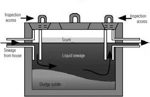
• Wastewater from building is discharged into the septic tank through a T-shaped inlet pipe. • Heavy solids settle at the bottom of the tank. • Lighter solids such as grease, oils and fats, rise to the top and form a scum layer. Solids that are not decomposed remain in the septic tank. • Bacteria grow in the septic tank and digest the solids and reduce the solids into liquid, fats and grease, and insoluble particles. • A T-shaped outlet pipe prevents the sludge and scum from leaving the tank and clogging the drain field area. • A relatively clear waste water flows out of the septic tank through the T-shaped outlet pipe.
DID yOu kNOw?
Septic tank uses anaerobic bacteria to digest the septage. Anaerobic bacteria are capable of living or growing in an environment lacking free oxygen.
Wastes containing excessive detergents, grease and disinfectants should not be treated in septic tank as they adversely affect the anaerobic decomposition.
Around the house • The grass over the system may become unusually green or spongy to walk on • Toilets, showers and sinks may take longer to drain • Occasional sewage odours may become noticeable, often after a rainfall • You may see gray or black liquids surfacing in your yard, or reversing through plumbing fixtures into the house In lakes and ponds • Leaks from septic systems can cause weeds and algae to grow in lakes and ponds. • Just a small amount of additional phosphorus (which can come from soaps, shampoos, household cleaning products and detergents) in a lake or pond can make a huge difference in the amount of weeds that grow during the spring and summer. • Lakes sometimes develop “dead zones” as a result of an overload of phosphorous – which can lead to too much algae, deplete oxygen supplies and kill fish.
Figure 42: Schematic of a septic tank
Connecting Building Drain to a Septic Tank – Key Steps:
Step 1: Collect key details about terrain and number of users in building Step 2: Connecting building sewage to a manhole Step 3: Connecting manhole to septic tank Step 4: Connecting septic tank to external disposal system
Conceived and drawn as per IS 2470 (Part 1) :1985 - Reaffirmed in 2001
or low waterlogging area. This will be useful to recommend the type of soil absorption system to be adopted after the septic tank. • Find out the number of people residing and /or using the building. The plumber based on the number of people should recommend the size and type of septic tank to be constructed.
DID yOu kNOw?
Septic tanks are recommended only for small communities and institutions whose contributory population does not exceed 300. For larger communities, provision of septic tanks should be avoided as far as possible. Reference SP35
Step 1: Collect Key Details about Terrain and Number of Users in Building
A plumber should collect the following details before planning the connection between building sewage and septic tank
Liquid depth in meters
Number of users Length (in Meters)
Breadth (in Meters)
cleaning interval - 1 year
5 1.5 0.75 1.0
10 2.0 0.90 1.0
15 2.0 0.90 1.3
20 2.3 1.10 1.3
cleaning interval - 2 years
1.05
1.40
2.00
1.80
Number of users Length (in Meters)
Breadth (in Meters)
cleaning interval - 1 year
50 5.0 2.00 1.0
cleaning interval - 2 years
1.24
100 7.5 2.65 1.0 1.24
150 10.0 3.00 1.0
200 12.0 3.30 1.0 1.24
1.24
300 15.0 4.00 1.0 1.24
Table 5: Recommended size for residential colonies IS 2470 (Part 1):1985 - Reaffirmed in 2001
Liquid depth in meters
Number of users Length (in Meters)
Breadth (in Meters)
cleaning interval - 1 year
50 5.0 1.60 1.3
100 5.7 2.10 1.4
150 7.7 2.40 1.4
cleaning interval - 2 years
1.4
1.7
1.7
200 8.9 2.70 1.4 1.7
300 10.7 3.30 1.4 1.7
IS 2470 (Part 1):1985 - Reaffirmed in 2001 Table 6: Recommended size for hostels and boarding schools
Note: A provision of 300mm should be made for free board. The sizes of septic tank are based on certain assumptions. While choosing the size of a septic tank, the exact calculation shall be made. for population over 100, the tank maybe divided into independent parallel chambers for ease of maintenance and cleaning.
Limitations of a septic tank
Because of the unsatisfactory quality of the effluent from the septic tank and also the difficulty in providing a proper effluent disposal system, septic tanks are recommended only for individual homes and small communities and institutions whose contributory population does not exceed 300.
For larger communities, septic tanks may be adopted with appropriate secondary effluent treatment and disposal facilities.
In such cases soak pit (Leech pit is also known as soak pit) is not recommended. The plumber should go in for other secondary treatments.
Step 2: Connecting Building Sewage to a Manhole
Material to be used – Material of the Building Sewer shall be either conventional salt glazed stoneware or UPVC rigid straight pipes of 6 kg/cm2 pressure class in manufacture and as per IS 15328:2003 with solvent cement joints.
• The building sewage in total is collected in a manhole for conveying to the septic tank for treatment. (Refer to Figure 43)
Figure 43: Typical layout of a septic tank sewarage system
• The layout should be simple and practical. Pipes should be as straight as possible. Bends should be avoided. Where it is not possible, long radius bends should be used.
Step 3: Connecting Manhole to Septic Tank
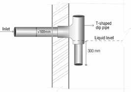
This is the most important connection in this form of disposal and the plumber should follow below mentioned guidelines strictly. 1. If the incoming drain is steep due to site conditions, the last section of the drain, at least 12 meters in length should not be laid at a gradient steeper than 1: 50 in order to minimize turbulence in the tank. 2. For practical considerations, a minimum nominal diameter of 100 mm is recommended. 3. The inlet shall be T-shaped dip pipe to avoid turbulence in the

Adapted from the Standard IS 2470 (Part 1): 1985 - Reaffirmed in 2001
* Figure not drawn to scale Conceived and drawn as per IS 2470 (Part 1) :1985 - Reaffirmed in 2001
tank. The pipe shall be fixed inside the tank, with top limb rising above scum level and the bottom limb extending about 300 mm below the top water level. Refer to Figure 44. 4. When the sewage is pumped to a septic tank, the sewage from the building sewer should be discharged into a small tank and then the sewage is allowed to flow into the septic tank by gravity to avoid turbulence inside the tank. 5. How connections inside a septic tank are made is discussed separately in Section 3 of this chapter.
Step 4: Connecting Septic Tank to External Disposal System
The plumber should follow the below mentioned steps to connect septic tank to external disposal system.
1. The final outlet for tanks should be at least by 100 mm nominal bore T shaped dip-pipe fixed inside the tank. The top limb of T-shaped outlet pipe should rise above scum level and the bottom limb should extend to about l/3 of the liquid depth below top water level. 2. The invert of the outlet pipe shall be 50 mm below the invert of 2 of this chapter for recommendations in size of septic tanks.
All dimensions are in mm only
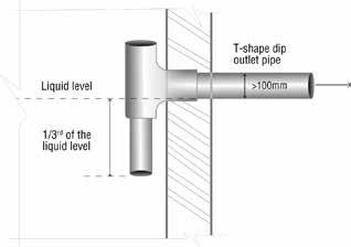
Conceived and drawn as per IS 2470 (Part 1) :1985 - Reaffirmed in 2001 Figure 45: T shaped dip outlet pipe
Conceived and drawn as per IS 2470 (Part 1) :1985 - Reaffirmed in 2001

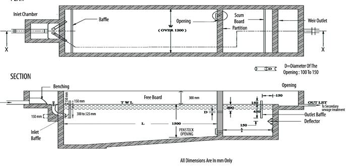
Figure 46: Position of invert of inlet and outlet pipe in septic tank the inlet pipe. 3. IS 2470 (Part 2): 1985 - Reaffirmed in 2001 – recommends following methods to safely dispose effluent from septic tank – Soil absorption system – best suitable for plains and where land area is available. – Biological filters – best suitable for high water table area and where land is limited. – Up flow anaerobic filters – best suitable for high water table area and where land is limited.
SECTION 3: Construction / connections in septic tanks – plumbers point of view
IS 2470 (Part 1): 1985 - Reaffirmed in 2001 provides design and construction specification for septic tanks. The sizes of the septic tank shall be based on number of users as per the above code. Refer to Section
A. Single Compartment Septic Tank for 20 users B. Two compartment septic tank for 50 users C. Two compartment septic tank for more than 50 users D. Duplicate septic tank for more than 100 users E. Precast Septic Tanks
A. Single compartment septic tank for 20 users
As per the IS 2470 (Part 1): 1985 - Reaffirmed in 2001, the sizing of the septic tank is based on the maximum flow in the building sewer is based on number of fixtures in the plumbing system.
a. Size:
• A minimum width of 750 mm, minimum depth of 1 m below water level and a minimum liquid capacity of 1000 litres is recommended. • For rectangular tank, the length shall be 2 to 4 times the width. • For circular tank - the minimum diameter shall be 1.3 m and the operating depth shall be greater than 1 meter.
b. Inlet:
• If the incoming drain is steep due to site conditions, the last section of the drain, at least 12 m in length should not be laid at a gradient steeper than 1: 50 in order to minimize turbulence in the tank • For practical considerations, a minimum nominal diameter of 100 mm is recommended. • The inlet shall be T shaped dip pipe to avoid turbulence in the tank. The pipe shall be fixed inside the tank, with top limb rising above scum level and the bottom limb extending about 300 mm below the top water level. Refer to Figure 44 in this chapter for better understanding.
c. Outlet:
The final outlet for tanks should be by 100 mm nominal bore T shaped dip-pipe fixed inside the tank. The top limb of T-shaped outlet pipe should rise above scum level and the bottom limb should extend to about l/3 of the liquid depth below top water level. The invert of the outlet pipe shall be 50 mm below the invert of the inlet pipe.
d. Free board:
A minimum free board of 300 mm should be provided. Refer to Figure 48 for details.
e. Vent pipe:
• Every septic tank shall be provided with ventilating pipe of at least 50 mm diameter. The top of the pipe shall be provided with a suitable cage of mosquito proof mesh. • The recommended height of the vent pipe should be 2 meters when the septic tank is at least 20 meters away from the nearest building. • If the septic tank is less than 20 meters from nearest building then the vent pipe should extend at least 2 meters above the highest point of the building.
f. Access opening:
• A septic tank shall be provided with a rectangular access opening measuring not less than 455 x 610 mm or a circular opening of 500 mm diameter. The cover should be water tight.
As per the IS 2470 (Part 1): 1985 - Reaffirmed in 2001, the sizing of the septic tank is based on the maximum flow in the building sewer, which is based on the number of fixtures in the plumbing system.
DID yOu kNOw?
A portion of sludge not less than 25 mm in depth should be left behind in the tank bottom which acts as the seeding material for the fresh deposits.
• Refer to section 2 for the recommended size of the septic tank. • Refer to section 3 for recommendation on access opening, free board and vent pipe.
Partitions:
• Here the tank may be divided into two chambers by means of a fixed durable partition. • The capacity of the first chamber is two third and that of the second chamber is one third. • For connecting the two chambers a rectangular or circular opening with minimum dia 100 mm and maximum 150 mm is provided in the partition at approximately 300 mm below TWL. • The digested sludge should be withdrawn through a dip pipe under a hydrostatic pressure of at least 450 mm. The sludge pipe shall deliver the sludge to the sump and be provided with a delivery valve to draw the sludge as required. • Portable pumps may also be used for de-sludging • Manual handling of sludge should be avoided.
Inlet
• It is same as septic tank with single chamber.
Outlet
• It is same as septic tank with single chamber.
As per the IS 2470 (Part 1) : 1985 - Reaffirmed in 2001, the sizing of the septic tank is based on the maximum flow in the building sewer is based on number of fixtures in the plumbing system • Refer to section 2 for the recommended size of the septic tank. • Refer to section 3 for recommendation on access opening, free
Figure 47 Typical sketch of two compartment septic tank for population upto 50

X X
* Figure not drawn to scale Adapted from the Standard IS 2470 (Part 1): 1985 - Reaffirmed in 2001
* Figure not drawn to scale Adapted from the Standard IS 2470 (Part 1): 1985 - Reaffirmed in 2001

Submerged Inlet Submerged Inlet

525 mm max 300 mm min
PLAN
Figure 49: Twin inlets for septic tank where width exceeds 1.2 m board and vent pipe and outlet pipe. • Where the capacity of a septic tank exceeds 2 000 litres, the tank may be divided into two chambers by means of a fixed durable partition. • The capacity of the first chamber is twice that of the second chamber.
Inlet
• When the width of the tanks exceeds 1.2 meters, two or more submerged inlets are preferable. • Submerged inlets are provided by using submerged bends of the same nominal bore (not less than 100 mm) set as closely together as practical in a shallow sump formed within a small benched chamber. • The invert of the benched channel should be 50 mm above the top water level in septic tank • The inlet ends of the submerged bends should be set flush with the floor of the sump. • Floor of the sump should be not less than 75 mm below top water level. • The inverts of the outlet ends of these bends should be between 300 and 525 mm below top water level in the tank. • Baffle refers to a flow-directing panel which helps to deflect, check and regulate the flow of sewage and helps reduce turbulence inside the septic tank. It should be provided 150 mm from the inlet end of the tank. It should extend 150 mm below the invert of the inlet pipes and 150 mm above the top water level. • For wider tanks (more than 2000 litres capacity), it is necessary to use a weir outlet extending the full width of the tank. • The weir outlet should be protected by a scum board fixed 150 mm from the weir. The top portion of scum board should extend 150 mm above the top water level and bottom portion of scum board should extend to one third (l/3) of liquid depth below the top water level. • A deflector should be formed either in the structure of the end (outlet) wall or by a purpose-made deflector to prevent rising particles from reaching the outlet weir.
DID yOu kNOw?

This deflector should be located 150 mm below the base of the scum board and protrude 150 mm into the tank
D. Duplicate septic tank for more than 100 users
TWL = Top Water Level SECTION Section X X
* Figure not drawn to scale Adapted from the Standard IS 2470 (Part 1): 1985 - Reaffirmed in 2001 All dimensions are in mm only
the design of septic tank given below, it is taken as 9 litres per minute.
• For population of over 100, duplicating tanks, each providing half the total calculated capacity required, should be installed and operated in parallel. • This arrangement permits all the flow to be passed through one unit while the other is being desludged. • To enable the top water to be decanted when desludging, a decanting valve should be provided in the wall dividing the two tanks; the invert of this valve should be 625 mm below top water level.
E. Precast septic tanks
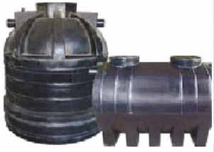
Precast Septic Tanks are manufactured in a factory and transported to the site for installation, thereby reducing Installation time and cost considerably. Moreover, the quality of the Septic Tank is also better than Cast-in-situ Septic Tanks as they are manufactured in controlled environments in the factory, thus ensuring water-tightness and material consistency.
Precast Septic Tanks are usually made of Polyethylene or Concrete. They have multiple chambers within them and a manhole for future maintenance. They are available in circular or in rectangular type for
Figure 50: Precast concrete septic tank the capacity required.
Adapted from keralaarchitect.blogspot.com
Precast concrete septic tanks in high water table area:
Precast concrete septic tanks are stronger than tanks made of steel, plastic, fiberglass, or high-density polyethylene (HDPE). Precast concrete is flexible enough to withstand extreme loading conditions. Precast concrete gradually strengthens over time. Other products, such as steel or HDPE, can deteriorate and lose strength.
Precast concrete septic tanks are installed in high water table area some times against the buoyant forces. With a specific gravity of 2.40, precast concrete septic tanks resist buoyant forces better than other septic tank materials and hence there will not arise the question of floatation. HDPE has a specific gravity of 0.97 and is more buoyant. Hence additional labor-intensive and time-consuming on-site preparation is needed for anchoring structures made of more buoyant materials.
Installation procedure
i) Make sure that the manhole is on top while lowering the Septic Tank into the dug area.
ii) Fill the Septic Tank with water completely before fixing the Sanitary Pipes, as a precaution against future settlement due to filled-weight.
iii) Make sure that there are no stones, gravel or sharp objects below the Poly-ethylene septic tank. Place it on smooth earth. An overflow pipe from the septic tank is to be connected to a Secondary Treatment Unit.
iv) If the Septic Tank has not been used for a while, fill it up with water by pouring it through the water closet.
v) Vent-pipe should be raised high from the ground so as to prevent foul smell at normal habitable height.

Adapted from www.lemanprecast.com
Figure 51: Pipe connection to precast septic tank
Common mistakes done by the plumbers:
FPO

Figure 52: Polyethylene septic tanks
Adapted from keralaarchitect.blogspot.com

Adapted from 15217.in.all.biz
Figure 53: Installation of precast septic tank
1. Septic tank is not constructed properly, No Ventilating pipe. 2. Toilet pipe discharges into a ring well type septic tank and percolates into the earth.
Septic tank Toilet discharge pipe
FPO

1. The waste water line is connected to the street drain.
FPO

Plumber can carry out a simple Percolation test to determine the type of soil absorption system suitable for disposal of septic tank effluent.
Percolation Test – To decide on the details of a soil absorption system, a soil absorption test is conducted. The percolation rate, that is, time required in minutes for water to fall 25 mm in the test-hole is determined. A test in trial pits at more than one place in the area
Septic tank
Position of the sub soil water level from ground level Soil and sub soil conditions
Porous soil with percolation rate
Not exceeding 30 minutes
Exceeding 30 minutes but not exceeding 60 minutes Dense and clays soil, with percolation rate exceeding 60 minutes
Within l.8 m Dispersion trench located partly or fully above ground level in a mound Dispersion trench located partly or fully above ground level in a mound Biological filter partly or fully above ground level with under-drains or up flow anaerobic filter and the effluent led into a surface drain or used for gardening
Below I.8 m Seepage pit or dispersion trench Dispersion trench Subsurface biological filter with under drains or up flow anaerobic filter and the effluent led into a drain or used for gardening
IS 2470 (Part 2): 1985 - Reaffirmed in 2001
Table 7: Recommended method for disposal of septic tank effluent
Note - Where the above mentioned methods are not feasible and where the effluent has to be discharged into open drain it should be disinfected
S No Percolation rate (Minutes)
1 2 3 4 5 6 7 8 9 10 1 or less
2 3 4 5 10 15 30 45 60
Maximum rate of effluent application (l/m2 / day) 204 143 118 102 90 65 52 37 33 26
IS 2470 (Part 2): 1985 - Reaffirmed in 2001
Table 8: Allowable rate of effluent application to soil absorption system.
Note: • The absorption area for a dispersion trench is the trench bottom area. • The absorption area for seepage pits is the effective side-wall area, effective depth being measured from 150 mm below invert level or inlet pipe to the bottom of the pit. • If the percolation rate exceeds 30 minutes, the soil is unsuitable for soakaways. If the percolation rate exceeds 60 minutes, the soil is unsuitable for any soil absorption system.
SECTION 4: Effluent disposal
Methods of treatment and disposal of effluent from septic tank (IS 2470 (Part 2) : 1985 - Reaffirmed in 2001)
Soil absorption system
Effluent Disposal
Soil absorption system, Biological filters, Up flow anaerobic filters
Do a Percolation Test
Design either Seepage pit/ Leach pit or Dispersion trench/ Drain field Determine the trench and sand mound
Design of Soil Absorption Systems – The allowable rate of application of effluent per unit area of dispersion trench or seepage pit is limited by the percolation rate of the soil.
There are three types of soil absorption system:
A. Seepage pit/ Leach pit B. Dispersion trench/ Drain field C. Secondary Treatment
Location of Subsurface Absorption System – A subsoil dispersion system shall not be closer than 18 m from any source of drinking water, such as well, to mitigate the possibility of bacterial pollution of water supply.
A. Seepage pit/Leach pit
• The seepage pit may be of any suitable shape with the least cross-sectional dimension of 0.90 m and not less than 1.0 m in depth below the invert level of the inlet pipe. • The pit may be lined with stone, brick or concrete blocks with dry open joints which should be backed with at least 75 mm of clean coarse aggregate • The lining above the inlet level should be finished with mortar. In the case of pits of large dimensions, the top portion may be narrowed to reduce the size of the RCC cover slabs. Where no lining is used, especially, near trees, the entire pit should be filled with loose stones. • A masonry ring may be constructed at the top of the pit to prevent damage by flooding of the pit by surface run-off. • The inlet pipe may be taken down to a depth of 0.90 m from the top as an anti-mosquito measure.
Figure 54: Leach pit
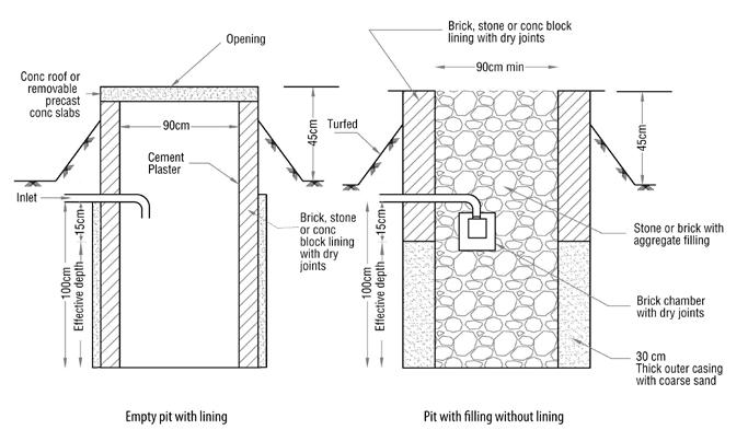
* Figure not drawn to scale Adapted from the Standard IS 2470 (Part 2): 1985 - Reafirmed in 2001
The plumber should take care of the gradient, size and the position of the inlet pipe from the pit bottom.
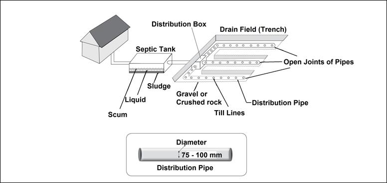
The Plumber should take care of the following while laying the pipes in a dispersion trench:
• Open jointing of pipes placed inside the trench. • The diameter of pipe should be between 75 – 100 mm. • Light gradient of pipe should be provided for smooth flow of effluent from septic tank to distribution box and then to the trench.
B. Dispersion Trench
• Dispersion trenches shall be 0.5 to 1.0 m deep and 0.3 to 1.0 m wide excavated to a slight gradient and shall be provided with 150 to 250 mm of washed gravel or crushed stones. • Open jointed pipes placed inside the trench shall be made of unglazed earthen-ware clay or concrete and shall have minimum internal diameter of 75 to 100 mm. • Each dispersion trench should not be longer than 30 m and trenches should not be placed closer than 2 m. • The covering for the pipes on the top should be with coarse aggregate of uniform size to a depth of approximately 150 mm. • The aggregate above this level may be graded with aggregate 12 to 15 mm to prevent ingress of top soil.
FPO
Figure 55: Dispersion trench
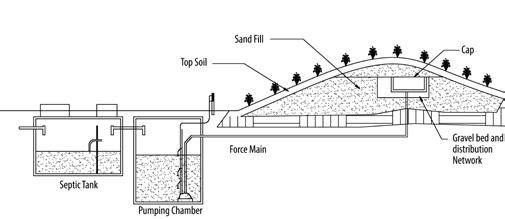
Figures 56: Sand mound
* Figure not drawn to scale Conceived as per IS 2470 (Part 2) : 1985 Reaffirmed in 2001 and drawn
FPO
Conceived as per IS 2470 (Part 2) : 1985 Reaffirmed in 2001 and drawn • The trench should be covered with ordinary soil upto 300 mm to form a mound (heap). The mound may be covered with the turf (Grass). • The finished top surface may be kept at least 150 mm above ground level to prevent direct flooding of the trench during rains.
Sand mound: In these systems, the effluent flows from the septic tank to a storage tank. The liquid is then pumped from the tank to perfo-
rated plastic pipes buried in a mound of sand built on the original soil surface. This system provides a layer of suitable soil thick enough to ensure adequate time and distance for proper treatment of the waste water. Vegetation growing on the mound helps to evaporate some of the liquid.
C. Secondary Treatment
Biological filters
• Biological filters are suitable for treatment of septic tank effluent where the soil is relatively impervious, water logged areas or where limited land area is available. It requires ample ventilation and an efficient system of under drains leading to an outlet. • The effluent from septic tank is brought into contact with a suitable medium, the surfaces of which become coated with an organic film. • The depth of medium should be between 900 - 1400 mm and should be retained in position by walls of adequate trench. The filter should have a concrete floor, laid to falls with a system of under drains laid on it and consisting of field drains half channels laid upside down and open jointed, or special tile discharging to the outlet. • The septic-tank effluent should be distributed evenly over the surface through which it percolates to the floor. Biological filters may be either rectangular or circular in shape and a series of fixed channels or rotating arm distributor may be used for distributing effluent on the medium. • Where the filter is below ground level, the vent pipes from the ends of the under drains should be carried to 150 mm above ground level outside the filter. • Normally the filter should not be covered, but wire netting may be used to prevent falling of leaves fouling the surface of the filter or blocking the ends of the vent pipe. • The filter effluent is either discharged into surface drain or evenly distributed over a grass plot from the system of channels. • For populations of up to 10 persons the volume of the filter medium should be 1 m3 of medium per head, of resident population. For over 10 and up to 50 persons, 0.8 m3 and for over 50 and up to 300 persons, 0.6 m3 .
Disadvantage of biological filters • Medium to High capital cost • Large land area required • Clogging danger
• Low volumetric loading rates • Possible odour problems or high volumes of waste air to be treated • Lot of excess sludge as byproduct which becomes difficult to dispose. • High operation cost for – aeration (power) – sludge disposal
Adapted from the Standard IS 2470 (Part 2) :1985 - Reaffirmed in 2001
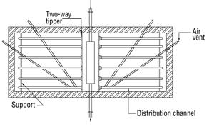
Figures 57: Rectangular biological filters

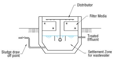
Figure 58: Circular biological filter
Up flow anaerobic filters:
These are used in areas where there is dense soil condition, high water table and limited availability of open land.
• The septic tank effluent is introduced from the bottom and the microbial growth is retained on the stone media making possible higher loading rates and efficient digestion. • The capacity of the unit is 0.04 to 0.05 m3 per capita or 1/3 to 1/2 the liquid capacity of the septic tank it serves. The effluent is clear and free from odour and nuisance. • In an up flow filter, the tank effluent enters at the bottom through a system of under drains, flows upwards through a layer of coarse material generally 0.6 to 1.2 m deep and is discharged over a weir or trough at the top. The driving head in the filter, that is, the difference between the water level and the filter may be as low as 25 to 150 mm during normal functioning.
Conceived and drawn as per CPHEEO Manual
The Plumber should take care:
1. Inlet & Outlet pipe with required size and gradient. 2. Providing air vent. 3. Flexible joints may be required on inlet or outlet connections, where rigid pipes are used.
I. Single chambered rectangular type:
• In this type, a rectangular chamber is constructed to treat the effluent from a normal domestic septic tank. • The chamber is packed with coarse material and the size of the packing media should be 20 mm.
Up flow anaerobic filters are of the following types:

i) Single chambered rectangular type,
ii) Double chambered rectangular type, and
iii) Circular type.
* Figure not drawn to scale Adapted from the Standard IS 2470 (Part 2) :1985 - Reaffirmed in 2001
• The medium rests on a perforated concrete false bottom slab. • The effluent from septic tank enters the bottom of the filter chamber through a 150 mm pipe and is distributed upward through the media from a perforated slab at the bottom. • The vertical inlet is fitted with a tee at the bottom, one branch of which leads to the filter and the other branch is kept plugged while the filter functions. • The plug can be removed to facilitate emptying into an adjoining chamber and cleaning the filter where required. • The effluent from the top of the bed is allowed to escape over a V-notch whose sill (bottom) level is kept 150 mm above the top of the medium.

II. Double chambered rectangular type:
The Plumber should take care:
1. Size and gradient of inlet pipe - T shaped dip pipe. 2. Level of the V Notch – 150 mm above the top of the medium.
• The filter consists of two interconnected compartments. • The first chamber is filled to a depth of 0.55 m with 20 mm coarse medium. • The second chamber is filled to a depth of 0.45 m with 20 mm size coarse aggregate. • The septic tank effluent falls through a perforated tray over the medium in the first compartment and enters the second compartment directly from the bottom. • The effluent passes up through the medium in the second chamber and escapes over a V-notch placed 75 mm above the top of the medium. • By this arrangement, the time of travel of the effluent through the filter is lengthened. • The two chambers are each fitted at the bottom with a 15 mm galvanized iron pipe leading to an adjacent chamber. • A valve in these pipes allows the filters to be partly desludged into the collecting chamber.
III. Circular Filter – A circular filter 0.9 m dia may also be constructed. • Medium of aggregate of uniform size 20 mm should be packed to rest on a perforated concrete slab. The effluent may be made to escape over the top of the medium through equally placed notches along the periphery of the filter. • The sill level is usually 100 mm above the top of the medium.
Adapted from the Standard IS 2470 (Part 2) :1985 - Reaffirmed in 2001
Figure 60: Double chambered rectangular up flow anaerobic filters
The Plumber should take care of:
• Size and gradient of inlet pipe. • Level of the V Notch – 75 mm above the top of the medium in the second chamber. • Providing 15 mm GI pipe with a valve for desludging.
Multi Chambered Up flow Anaerobic Filters:
Up flow type of filters (reverse filter) operating under submerged conditions is a method for disposal of septic tank effluents in areas where there is dense soil condition, high water table and limited availability of open land. The septic tank effluent is introduced from the bottom and the microbial growth is retained on the stone media making possible higher loading rates and efficient digestion. The capacity of the unit is 0·4 to 0·5 m3 per capita or 1/3 to 1/2 the liquid capacity of the septic tank it serves. BOD removal of 70 percent can be expected and the effluent is clear and free from odour and nuisance.
This technology consists of a sedimentation tank (or Septic Tank) followed by one or more filter chambers. Filter material commonly used includes gravel, crushed rocks, cinder, or specially formed plastic pieces. Typical filter material sizes range from 12 to 55 mm in diameter. Ideally, the material should provide between 90 to 300 m2 of surface area per 1 m3 of reactor volume. By providing a large surface area for the bacterial mass, there is increased contact between the organic matter and the active biomass that effectively degrades it.
Hydraulic Retention Time (HRT) is the most important design parameter influencing filter performance. An HRT of 0.5 to 1.5 days is a typical and recommended.
In this type, the effluent from the septic tank enters at the bottom,
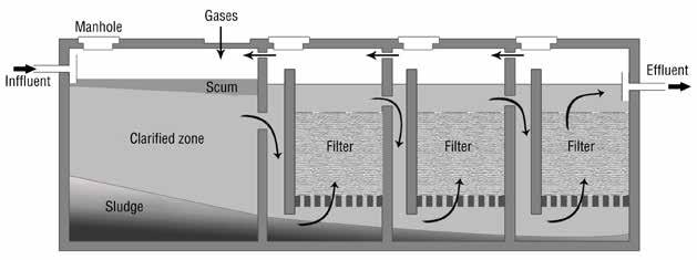
through a system of under drains, flows up wards through a layer of coarse materials as stated above generally 0.6 – 1.2 m deep and discharge into the inlet of successive chambers. Final discharge is over a weir or trough at the top.
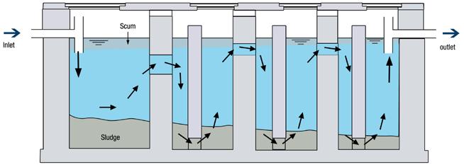
Baffle reactor septic tank:
Description: An Anaerobic Baffled Reactor (ABR) is an improved septic tank because of the series of baffles over which the incoming wastewater is forced to flow. The increased contact time with the active biomass (sludge) results in improved treatment.
The majority of settleable solids are removed in the sedimentation chamber at the beginning of the ABR, which typically represents 50% of the total volume. The up-flow chambers provide additional removal and digestion of organic matter: BOD may be reduced by up to 90%, which is far superior to that of a conventional septic tank. As sludge is accumulated, desludging is required every 2 to 3 years. Critical design parameters include a hydraulic retention time (HRT) between 48 to 72 hours, up-flow velocity of the wastewater less than 0.6 m/h and the number of up-flow chambers (2 to 3). This technology is also appropriate for areas where land may be limited since the tank is installed underground and requires a small area.
It should not be installed where there is a high groundwater table as infiltration will affect the treatment efficiency and contaminate the groundwater.
This technology can be efficiently designed for a daily inflow of up to 200,000 L/day. The ABR will not operate at full capacity for several months after installation because of the long start up time required for the anaerobic digestion of the sludge. Therefore, the ABR technology should not be used when the need for a treatment system is immediate.
Because the ABR must be emptied regularly, a vacuum truck should be able to access the location. ABRs can be installed in every type of climate although the efficiency will be affected in colder climates.
Figure 62: Baffle reactor septic tank
Health Aspects/Acceptance: Although the removal of pathogens is not high, the ABR is contained so users do not come in contact with any of the wastewater or disease causing pathogens. Effluent and sludge must be handled with care as they contain high levels of pathogenic organisms. To prevent the release of potentially harmful gases, the tank should be vented.
Maintenance: ABR tanks should be checked to ensure that they are watertight and the levels of the scum and sludge should be monitored to ensure that the tank is functioning well. Because of the delicate ecology, care should be taken not to discharge harsh chemicals into the ABR. The sludge should be removed annually using a vacuum truck to ensure proper functioning of the ABR.
Advantages:
1. Resistant to organic and hydraulic shock loads 2. No electrical energy required 3. Grey water can be managed concurrently 4. Can be built and repaired with locally available materials 5. Long service life 6. No real problems with flies or odours if used correctly 7. High reduction of organics 8. Moderate capital costs, moderate operating costs depending on emptying; can be low cost depending on number of users
Conceived and drawn as per CPHEEO Manual
Field Study exerciSe
Place to Visits: Visit a septic tank under construction and a septic tank of a multi-storied building.
Exercise
• Divide Trainees into groups of 4 people. • Ask them to prepare a checklist of key items to be inspected in the field visit • Make each group inspect the septic tanks using their checklist and report findings • Instructor to use this checklist to educate trainer on what observations were correct and what were not observed at all.
Minimum points to check:
• Required slope for the inlet pipe of a septic tank. • Provision of vent pipe with cowl and mosquito mesh. • Height of the vent pipe. • At junctions of pipes in manholes, how branch connection is made. • Inlet and outlet – T shaped dip pipe. • Effluent disposal.
Disadvantages:
1. Requires constant source of water 2. Effluent requires secondary treatment and/or appropriate discharge 3. Low reduction pathogens 4. Requires expert design and construction 5. Pre-treatment is required to prevent clogging
Constructed wetlands: is a natural, low-cost, eco-technological biological wastewater treatment technology designed to mimic processes found in natural wetland ecosystems.
Constructed wetland is a shallow basin filled with some sort of filter material (substrate), usually sand or gravel, and planted with vegetation tolerant of saturated conditions. Wastewater is introduced into the basin and flows over the surface or through the substrate, and is discharged out of the basin through a structure which controls the depth of the wastewater in the wetland.
There are 2 types of constructed wetlands
Discharge from septic tank

Discharge to ground
Figure 63 : Surface flow constructed wetlands
Adapted from en.wikipedia.org
1. Surface flow constructed wetlands system – the waste water is distributed on a carefully contoured land with sprinklers. This is more suitable for many types of soil including bay mud and silt clay.
Some characteristics of this type of surface constructed wetlands are
• Large land-area requirements to purify water—20 square meters (220 sq ft) per person • Increased smell • Poor purification in winter 2. Sub surface flow constructed wetland – the waste water is allowed to flow through a gravel or sand medium on which plants are rooted.
There are two types of sub surface constructed wetlands

• Horizontal flow filters – waste water is distributed horizontally below the surface and water is allowed to flow between the roots. • Vertical flow filters – waste water is distributed with help of a
Discharge from septic tank
Discharge to ground
Figure 64: Horizontal subsurface constructed wetlands
Adapted from en.wikipedia.org
dosing device on 2 or 3 filter beds which are charged alternatively.
Horizontal subsurface constructed wetlands
the porous substrate under the surface of the bed in a more or less horizontal path until it reaches the outlet zone. During this passage the wastewater will come into contact with a network of aerobic, anoxic and anaerobic zones
Some characteristics of this type of Horizontal subsurface constructed wetlands are:
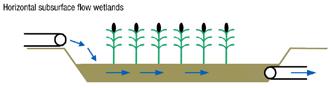
• System is more efficient • Doesn’t attract mosquitoes • Less odourous • Less sensitive to winter conditions • Less area is needed to purify water—5–10 square meters (54–110 sq ft)
Size of Horizontal wetland system
Warm climate zone
• For organic loaded sewage (for black and grey water combined), with an average water level of 0.50 m, 3.5 m2 size is required for 150 Liter discharge • For black water treatment only, 2 m2 area is required for 50 L discharge
Cold climate one
• For organic loaded sewage (for black and grey water combined), with an average water level of 0.50 m, 7 m2 size is required for 150 Liter discharge
Vertical subsurface constructed wetlands
This type of wetland comprises a flat bed of sand/gravel topped with sand/gravel and vegetation. Wastewater is fed from the top and it gradually percolates down through the bed before it is collected by a drainage network at the bottom.
Some characteristics of this type of vertical subsurface constructed wetlands are
• Requires less space than Surface wetlands • Dependent on an external energy source • Increased efficiency requires only 3 square meters (32 sq ft) of space per person
Discharge from septic tank
Figure 65 : Vertical subsurface constructed wetlands
Discharge to ground
Adapted from en.wikipedia.org
Option A Option B
Septic tank should be located at a place Sewage flow to a septic should be In case of a rectangular tank, the length
Inside the building
Smooth/laminar
Shall be 5 times the width. away from the building
Rough/turbulent
Shall be 2 – 4 times the width.
Lighter solids that float such as grease, oils and fats, rise to the top and form sludge layer and form a scum layer
The inlet shall be T shaped dip pipe
to create turbulence in the tank. to avoid turbulence in the tank.
A minimum free board of Every septic tank shall be provided with ventilating pipe of In a two chamber septic tank the capacity of the first chamber is Septic tanks are recommended only for small communities and institutions whose contributory population Effluent from the septic tank shall be disposed off by
300 mm should be provided. 400 mm should be provided.
at least 50 mm diameter at least 75 mm diameter
Thrice that of the second chamber. Twice that of the second chamber.
does not exceed 400 does not exceed 300
Biological filters Soil absorption system
Case study Connecting building drainage to septic tank and Other Decentralised Systems
Aim of the Cases – The aim of the 2 cases listed below is to highlight the various standards / procedures established for connecting households to septic tank and connecting septic tank to individual disposal system plumbing in a building. In case study 1 a schematic diagram of the cross section of septic tank is to be used to elicit the trainees to identify various standards / parameters set for septic tanks and to highlight what are common areas of violations by plumber. In case study 2 – schematic diagram of an individual disposal system is to used, to highlight the environmental impact the set up could have if it is not planned correctly.
Time allotted: 20 minutes / Case
Instruction to Trainer – The case is to be discussed at the end of a training session of a chapter. This will serve to recollect key concepts learnt, bring out the level of understanding of trainees and emphasize the real impact behind theoretical concepts.
The trainer will show the Figure to the trainees and explain the various components visible in the Figure to the trainees. Alternatively, one or more of the trainees could be invited to describe the various components visible in the Figure. Then the case is open for discussion for 10 to 15 minutes. The trainer should use a flip chart or board to capture key points of discussion. Finally the trainer is to summarize the discussion and explain the impact wrong connection depicted in photographs would have.
This will create a lasting impression / retention among the trainees.
Case study 1 Open to trainees for their inputs and comments
Trainer’s case discussion – key points:
1. No vent pipe. 2. The invert level of outlet pipe must be 50 mm lower than the invert of inlet pipe.(IS 2470 (Part 1): 1985 - Reaffirmed in 2001) 3. Only the liquid effluent is passed out. 4. The bottom limb of inlet pipe should be extended up to 300 mm below the top water level. 5. The bottom limb of outlet dip pipe should be 1/3 of liquid depth below top water level. 6. Floor - A minimum slope of 1:10 should be provided towards the sludge outlet to facilitate desludging. 7. A free board of 300 mm should be provided.
Case study 2
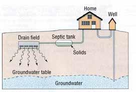
Figure depicting septic tank with dispersion trench
Open to discussion among all trainees
Trainer’s case discussion – key points:
1. Understand the possibility of drinking water getting polluted by the proximity of dispersion trench. 2. Explain the health impact it could have on people.


