23 minute read
CHAPTER 2: Overview to Public Sanitation Systems and Process


Overview to Public Sanitation Systems Basic Concepts of Plumbing and Process
Chapter Objective:
Advertisement
• Provides a step by step approach to be followed by a plumber in connecting building drainage system to a public sewerage system.
• Highlights the role of a manhole, precautions a plumber has to consider for certain types of traps, right ways to connect various types of pipes and recommendations as prescribed in the national plumbing standards.
• Provides brief description about simplified sewers and small bore systems
Chapter Duration: 180 minutes*
SECTION 1: Building sewerage & its components
Basic definitions
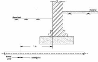
Building drain – refers to the lowest horizontal pipe of a drainage system which receives the discharge from soil, waste and other drainage pipes inside the walls of the building. It extends for up to 1 meter from building and discharges into the Building sewer.
Building sewer – refers to the horizontal pipe of a drainage system which collects drainage from the building drain and discharges the same into the Public sewerage system, private sewer or individual sewage disposal system.
Ground level Floor level
1 m
Building Sewer Building Drain * Figure is not drawn to scale Adapted from the Standard IS 5329:1983 - Reaffirmed in 2001
Crown – refers to the highest interior level, and can be considered the “ceiling” level.
Public Sewer System
A. Combined Sewer System
B. Separate Sewerage Systems
C. Partially Separate Sewerage Systems
* Not drawn to scale Conceived and drawn as per IS 1742: 1983 - Reaffirmed in 2002
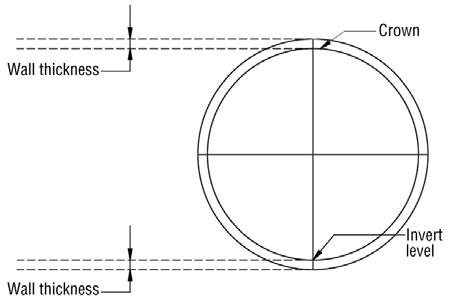
Figure 23: Invert and crown in a pipe
Public Sewer System (PSS) – refers to sewerage system operated by municipalities or corporations. It collects sewage / storm water from individual buildings, public areas and transports it for proper disposal. The PSS can be classified into following categories: A. Combined sewer system – sewage and storm water/surface water runoff are drained through the same pipes in a single pipe system. This system can cause serious water pollution problems when the combined sewer overflows during rainy season or a storm. B. Separate sewer system – sewage and storm /surface water runoff are drained through two different pipes. Sewage and storm / rain water are handled separately and hence chances of pollution is minimal.
C. Partially separate sewer system – part of storm water is mixed with sewage and drained through one pipe and rest of the storm water is collected using another pipe. Manhole – refers to an opening by which a man may enter or leave a drain, a sewer for inspection, cleaning and other maintenance opera-
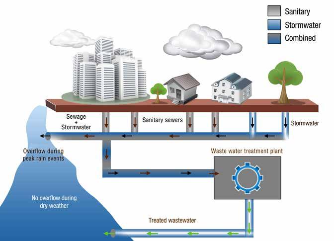
Figure 25: Separate sewer system
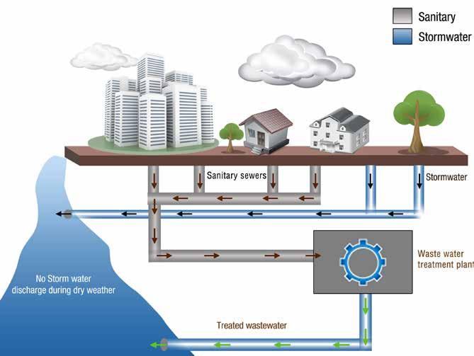
Adapted from www.dcwater.com
tions. Some key details about manhole are listed below:
• Cover: – Is a cover / lid to close the opening. – This is important to prevent accidents and foul gases from polluting the building premise. – Circular covers are desirable. – Size of the cover should be at least 500 mm for a manhole exceeding 0.9 meters in depth.
• Structure: – Usually brick walled. Concrete or pre-cast structures are also used.
• Shape: – Rectangular in shape if manhole is less than 1 meter in depth. – Circular manholes are recommended when depth exceeds 1 meter.
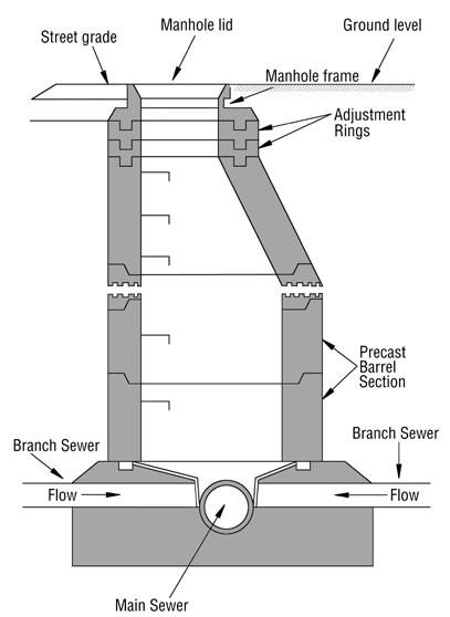
• Standards for compliance: – IS 1726:1991 - Reaffirmed in 2003 & IS 11972:1987 - Reaffirmed in 2002; Requirements for manhole covers and frames.
Drawn as per IS 1742 :1983 - Reaffirmed in 2002
Figure 26: Cross section of a manhole
• Normally the whole sewerage system of any town will be marked on a plan and divided into sections and areas and are placed under a maintenance team.
• The locations of manholes sewers and laterals could be identified from the map.
• In case of very old sewerage systems the location of the manholes could be identified with the use of mechanical devices such as metal detectors etc.
• The location of manholes may be identified by visualizing their covers which are normally metallic.
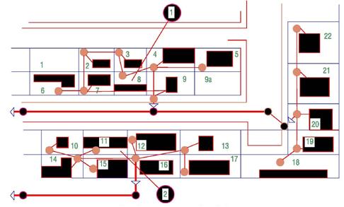
• The map or the plan will give information on mapping, inventory, and recording of geographical location of all public and private sanitary sewer manholes (by identifying numbers), public and private sewer mains, force mains and air valves, service line cleanouts, and lift stations in the wastewater collection system.
• The Manhole Identifier Map in Figure 27 illustrates numbering by sewer shed and trunk line, a flexible numbering system, and lower numbers toward each sewer shed outlet,
The mapping of private sewers, may not be available with the maintenance team. The same should be obtained from the property owner.
The Plumber should follow the below mentioned steps in connecting building drain to Public sewer
Step 1: Establish Details about the PSS Step 2: Connecting – Preliminary Works Step 3: Connecting
Step 1: Establish Details About The PSS
The Plumber should first gather the following details before starting any plumbing work to connect building drainage to Public sewerage system.
• The position of the public sewer in relation to the building
• The invert level of the public sewer.
• Check if the Public Sewer System (PSS) is combined, separate or partially separate system.
• Clarify the lowest level at which connection from building may be made to the PSS.
Step 2: Connecting Building Sewerage Pipe To Municipal Manhole – Preliminary Works
Material to be used – Material of the Building Sewer shall be either conventional salt glazed stoneware or UPVC rigid straight pipes of 6 kg/ cm2 pressure class in manufacture with solvent cement joints.
Size of Building sewer connection – should preferably be 150 mm or more in diameter with a minimum slope of 1:60 laid as far as possible to a straight line and grade. Tips to measure slope are provided at end of this section.

FPO
Conceived and drawn as per CPHEEO Manual
FPO FPO FPO
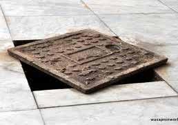
Figure 28: Manhole / Manhole covers


Conceived and drawn as per IS 1742:1983 - Reaffirmed by in 2002
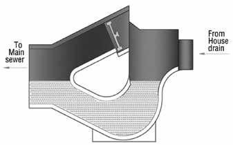
Figure 29: Waste water / grey water line connected to manhole through gully trap
Procedure for connecting building sewer to manhole:
Before connecting the Building Sewer to the Municipal Manhole, the plumber should verify the following:
1. All drainage pipes from the building are connected to Inspection chamber inside the building premises.
2. Waste / Grey water discharged from the building is connected through a Gully trap to Inspection chamber outside the building.
Refer to Figure 29 for better understanding.
3. Inspection chambers shall be provided at each corner immediately outside the building in case of large buildings.
4. Soil / Black water discharged from building is connected to manhole outside the building directly.
5. It may be noted that a manhole/ inspection chamber is provided
at change of
– alignment – gradient – diameter of a drain – Bends and junctions in the drain
6. Where diameters of the incoming and outgoing drain are different, the crown of the two pipes should be fixed at the same level.
7. All inspection chambers in the building are inter-connected and the drain leads to a final inspection chamber within the building premise.
8. Then this final inspection chamber is connected to the Municipal manhole outside the boundary of the building premise in case of large buildings.
9. In case of small buildings, the building drain and building sewer may be connected as illustrated below. The building sewer may be lead to Municipal manhole connection.
below GL
Conceived and drawn as per IS 5329 : 1983 - Reaffirmed in 2001
Figure 30: Building drain and building sewer connection
DID yOu kNOw?
The earlier practice has been to connect house sewers to public sewers using the typical Y branch or T branch depending on the depth of public sewer. It is discontinued and the house service sewer connections are done only in manholes as per recommendations from CPHEEO manual. In case of old sewers, a new manhole shall be inserted for this purpose.
Step 3: Connecting Municipal Manhole to Public Sewerage System (PSS) Procedure for connecting building sewer to manhole:
The plumber should follow the steps listed below when connecting Manhole at building boundary to PSS.
1. The house sewer should be connected to the public sewer with the approval and as directed by the authority.
2. The building sewer leading to the municipal manhole is called lateral.
3. If the difference in level between the incoming drain and the outgoing sewer is less than 600 mm and there is sufficient room in the manhole, the connecting pipe may be directly brought through the manhole wall and the fall accommodated by constructing a slope in the manhole (Ref: IS 1742:1983 - Reaffirmed in 2002).
4. Intercepting trap is often provided at the junction of a building sewer and a public sewer. This intercepts the foul gas from the municipal sewer, from entering into the building drainage system. This trap is also called as a boundary trap.
The recent practice is to make the house connection directly without providing intercepting traps. Intercepting traps may be useful for multistoreyed houses.
Trouble shooting
In case a public sewer becomes surcharged /flooded due to heavy rain
Conceived and drawn as per IS 1742 : 1983 - Reaffirmed in 2001
Figure 32: Intercepting trap / boundary trap
or storm, gullies and sanitary fittings shall be located above the level of maximum surcharge. Anti-flood valve shall be provided in the manhole nearest to the junction of sewer and sewer drain. Any NRV (Non return valve) can also be used for this purpose.
When the elevation of an incoming sewer in a manhole considerably exceeds (greater than 600 mm) that of the outgoing sewer; a vertical waterway outside the manhole is provided to divert the waste water from the upper to the lower level so that it does not fall freely into the manhole except at peak rate of flow. This arrangement is called drop down manhole.

* Figure is not drawn to scale Conceived and drawn as per CPHEEO Manual
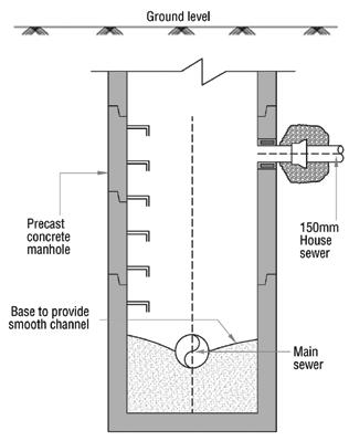
Figure 31: Building sewer to manhole connection Figure 33: Anti-flood valve
Conceived and drawn as per IS 1742 : 1983 - Reaffirmed in 2001
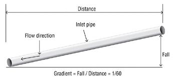
Tips to measure the gradient or slope while laying pipes.
Pipe slope / gradient: Slope or gradient may be defined as fall divided by the distance.
Gradient = Fall / distance
Sample Calculation of fall: If your drainage pipe length (L) is 15 metre, what is fall (F) required to attain gradient of 1:60?

Drawn as per IS 1742 :1983 - Reaffirmed in 2002
Figure 34: Drop down manhole Figure 35: Fall and gradient in drainage pipe
Conceived and drawn
Answer:
Slope of 1:60 means the slope will fall 1 meter for 60 meter length of pipe.
Our Pipe length (L) = 15 meters
So Fall = Gradient * distance
Fall = 1/ 60 * 15 = 0.25 meters
Fall should be 0.25 m or 25 cm.
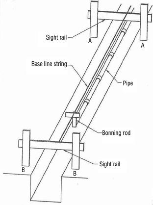
Procedure to measure gradient for laying of sewerage pipe:
1. Mark the width of the trench on ground with chalk powder and start excavating to the required depth.
2. Drive two pegs on the side of the trench at the starting point at a distance of 600 mm from the trench mark.
3. Mark the level on both pegs using water level. Fix a sight rail at the mark.
4. Calculate required slope up to the end of the trench as illustrated in Figure 36.
5. Fix two more pegs at the end as done earlier. 7. Fix a sight rail at mark.
8. Tie a string from sight rail at the starting point to the end tightly.
9. Check the bottom level of the trench using a boning rod. (Level of trench to be exactly equal from string)
Sewerage pipes are to be laid as per the gradient recommended to have normal flow bearing in mind the self-cleaning velocity to avoid settlement of sewage in the pipe line. In places where required gradient is not conducive, care should be taken to lay the pipes in such a slope that the flow of sewage inside the pipe is smooth and non clogging.
FPO
Figure 36: Measuring gradient / slope
Adapted from Plumber Trade Practical Book
SIMPLIFIED SEWERS: Simplified sewers or Condominial
sewers are low-cost sewers which are mainly used in high-density, low-income settlements especially where laying of sewer lines are problematic.
They consist of a network of small diameter pipes laid flat on the ground away from traffic or vehicle movements. Since it is mainly used in low income settlements, the technology is cheaper than conventional gravity pressured sewerage system. As simplified sewers are used in residential areas, they can be laid at relatively shallow depths due to the absence of heavy traffic.
The design of a simplified sewer is basic, having a layout with inspection chambers instead of manholes. This reduces construction costs, facilitates cleaning, and makes it easier and cheaper to connect households to the system. 1. Connected to a conventional street sewer. 2. The waste water can be discharged into a septic tank set up for the community and then by a small bore sewer to any other form of secondary treatment. 3. The discharge can be sent to the Sewage Treatment Plant (STP) directly for further treatment.
Advantages:
• This systems reduces water requirement compared to the conventional sewerage system since the simplified sewer systems are designed for frequent flushing. • Lengths of pipe are reduced since short house service connections are required. • Reduced excavation costs since shallow depths are adopted. • Reduced material cost since small diameter pipes are used.

Adapted from UN Environment Prgoramme - Waste water & Storm water Collection
Figure 37 A: Conventional gravity sewers layout
Adapted from UN Environment Prgoramme - Waste water & Storm water Collection Figure 37 B: Condominium sewer - simplified sewer layout • Reduced maintenance requirements. • Reduced treatment requirement. • Cost of construction of simplified sewerage is 30 to 50 % less than conventional sewerage
Connections in Simplified sewer grid can be of two types • Fishbone grid system • Right angle / rectangular grid system
Fish bone grid system/ Herring bone
system: The layout has the similarity of Herring Fish. It consists of parallel laterals that enter the main from either side at angle. The main line or sub main lies in the narrow depression, particularly suitable where laterals are long & required area to be thoroughly drained.
Laterals enter the main only from one direction hence the cost of this system is comparatively less. This system is used on flat land/regularly shaped field on uniform soil.
Placing the main on each side of depression serves a dual purpose. It intercepts the seepage & provides outlet for the laterals. (Ref: AgriInfo.in)
Rectangular Grid system: Simplified sewers of rectangular grid are best suitable for dense informal settlements where laying sewer lines are often problematic due to the unplanned, irregular layout of buildings and streets.
Settled sewerage originated to convey the overflow from septic tanks where the soil cannot cope or absorb the overflow. This usually occurs when the groundwater table is high, or where the soil permeability is low, or where there are rock outcrops. This was developed to overcome problems with failing septic tanks; it has been used quite widely to upgrade septic tank systems.
Small bore system – settled sewerage system
Settled sewerage system or solid free sewers refer to the sewerage system required for conveying the wastewater that is pre-settled and where solids have been removed. Ideally solids would have settled for example in a septic tank.
Settled sewerage system
This method is known as Septic Tank Effluent Disposal Scheme (STEDS). The idea is that only liquid water flows through the system. Settled sewerage requires that only connections from septic tank are made to the settled sewer. Septic tanks are regularly emptied of solids to prevent solids from passing through.
Sewered interceptor tank
This system is known as Sewered Interceptor Tank Systems (SITS). Where there is no existing septic tank, an interceptor box or tank can be used and functions like a septic tank. As a result, since there is no requirement for the self-cleansing velocity to remove solids, small bore sewers can be used. Since the sewers are not required to carry solids, large quantities of water are not needed for solids transport. The cost of settled sewerage is between a third and a half of conventional sewerage. The waste water from a group of houses can be connected to one interceptor tank. Just like in a septic tank, the accumulation of sludge has to be removed regularly from an interceptor tank. The sewers are small bore plastic pipes of minimum diameter of 100 mm. The effluent from interceptor tanks transported through small-bore sewerage can be discharged into conventional sewerage or treated locally in a decentralized wastewater treatment plant.
Adapted from UN Environment Prgoramme - Waste water & Storm water Collection Figure 38: Interceptor tank in settled sewerage system
Vacuum sewers:

Low-cost sewers conveying wastewater to distributed treatment systems and various alternative and advanced onsite systems are known collectively as “decentralized wastewater technologies”. The collection systems typically are called “alternative collection systems”. One such system is vacuum sewers.
The vacuum sewer collects sewage from multiple sources and coveys it to a central location where it can be treated. As the name suggests, a vacuum is maintained in the collection system and when a house sewer is opened to atmospheric pressure, sewage and air are pulled in to the sewer, whereby the air forms a “plug” in the line, and air pressure pushes the sewage to the vacuum station. This differential pressure comes from a central vacuum station.
These sewers can take advantage of available slope in the terrain, but are most economical in flat terrain. Vacuum sewers have the limited capacity to pull water uphill may be to 9 m. Vacuum sewers are designed to be watertight since any air leakage in to the system reduces the available vacuum.
Vacuum sewers do not require a septic tank at each waste water source. All of the domestic waste water and waste constituents are collected and transported by this collection method. Sewage from one are more homes flows by gravity in to a small valve pit. A service line connects the valve pit to the main vacuum line.
Vacuum stations will consist of two or more vacuum pumps and a large vacuum tank. The pumps run 3 – 5 minutes cycles or long enough to create adequate vacuum in the system. The tank at the vacuum station holds the vacuum on the collection network and prevents the vacuum pump from having to operate continuously. As valve pits are activated, there is loss in the vacuum (negative pressure) in the system. When the negative pressure reaches a threshold level, the vacuum pumps reengage to pull more vacuum. When sewage reaches the vacuum station, it flows in to a collection tank. Sewage pumps are then used to convey the collected sewage through a force main to the treatment component.
A disadvantage is the need to ensure unfailing power supply to the pumps and hence this system is perhaps limited high profile condominiums
Small-bore sewerage (also known as solids-free sewerage or SITS— sewered interceptor tank systems) Vacuum Sewers Description
Sewers are laid at shallow depths and manholes are replaced with access chambers for cleaning. Reduced cost and ease of maintenance. In residential areas where traffic loads are low Protection, in the form of concrete surround or cover slab, required at road crossings
Interceptor tanks on household connections and small pipes of 100 mm diameter. Removal of settleable solids in interceptor tanks reduces sedimentation in sewers and allows them to be laid to much shallower Gradients. Where ground slope is low or the water table is high. Regular removal of solids from interceptor tanks required. Vulnerable to illegal connections by households.
Vacuum sewer system uses the differential pressure between atmospheric pressure and a partial vacuum maintained in the piping network and vacuum station collection vessel. Reduced cost. Vacuum sewers offer exceptional environmental, operational and financial benefits. Construction of conventional gravity system would be costly. Housing density is low. Terrain slopes are insufficient or too steep. Groundwater tables are high. Only the few pumps in the vacuum station need electrical power, service and maintenance.
Table 3: Alternative sewerage options for residential areas
Technology options for Urban sanitation - MoUD
Field Study exerciSe
Place to Visits: Visit a building whose sewer is connected to public sewerage system:
Exercise
• Divide Trainees into groups of 4 people. • Ask them to prepare a checklist of key items to be inspected in the field visit • Make each group inspect the draining system using their checklist and report findings
Points to check:
1. Under which drainage system, the building sanitary pipe work is done. 2. Is there a boundary trap? 3. Is there any anti flood valve? 4. Is the wastewater line connected to the sewer through gulley trap? 5. In the bottom of the soil line, is there a bend with long radius?
Quick Test: To recap the key points in the chapter.
Check and tick if the following statements are True or False
The discharge from water closet and urinal is called grey water A fixture acts as a bridge The soil appliances which collect and discharge excretory matter discharge through traps into a soil pipe and then to the building drain through a gully trap The two pipe system contains one soil pipe, one waste pipe and one ventilating pipe In the two pipe system, the separation between black water and grey water is not possible Building sewer is the extension of building drain In plumbing, the highest point or the highest inside surface of a channel, conduit, drain, pipe, or sewer pipe is the invert level In the case of bends in the bottom most pipes, they should necessarily be of long radius and should preferably be made of 90o bends All the pipes those laid on the external face of the walls should be made of metal Ventilating pipes may be fixed horizontally
True False
Case study: Overview to public sanitation systems and process
Aim of the Cases – The aim of the first 2 cases listed below is to highlight the various standards established for connecting a building drainage to PSS. Cases will highlight the violations made by plumbers in connecting building drainage to PSS and the corresponding impact that will have on sewerage disposal / surrounding environment.
Time allotted: 20 minutes / Case
Instruction to Trainer: – The case is to be discussed at end of a training session of a chapter. This will serve to recollect key concepts learnt, bring out the level of understanding of trainees and emphasize the real impact behind theoretical concepts.
The trainer will show the photographs to the trainees and explain the various components visible in the photograph to the trainees. Alternatively, one or more of the trainees could be invited to describe the various components visible in the photograph. Then the case is open for discussion for 10 to 15 minutes. The trainer should use a flip chart or board to capture key points of discussion. Finally the trainer is to summarize the discussion and explain the impact wrong connection depicted in photographs would have.

This will create a lasting impression / retention among the trainees.
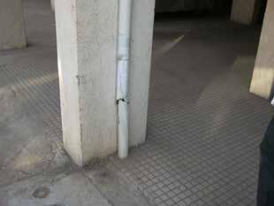
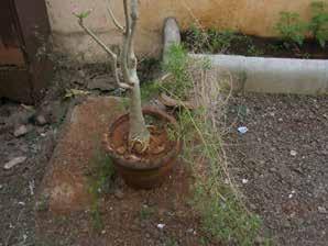
Case study 1 Case Description – key points:
1. A rain water pipe is running along the column (Pipe Damaged) 2. MH outside the building. 3. A septic tank 4. The building drain is connected to the septic tank. The rain water is also connected to the drain. 5. Septic tank outlet is connected to the Municipal MH on the road. 6. It is ascertained that the septic tank has not been desludged for quite some time.
Trainer’s case discussion – key points:
1. Rain water pipes should not be connected to the building drain and in turn to the street sewer without approval of the authority as this action will over load the street sewer and the chances of street sewers getting flooded very high. The rain water pipe should be normally connected to the storm water drain. 2. The septic tank should be provided with a ventilating pipe. 3. The septic tank acts like an interceptor tank. This has to be cleaned periodically.
Soil pipe discharge to the septic tank Extension of soil pipe for ventilation Soil pipe

Waste water pipe
Figure of a residential building with one floor
Case study 2 Case Description – key points:
1. The area is not sewered. 2. Soil pipe discharge into a septic tank. 3. Wastewater line discharges into the street drain.

FPO
Outlet Septic Tank Manhole
Figure of a multi-storey building Manhole Rain water pipe Waste water pipe to street drain
Case Study
4. Vent pipe diameter should be of the same diameter as soil pipe.
In the Figure the vent pipe diameter is smaller than soil pipe. 5. The vent pipe is not extended up to the roof top. 6. Septic tank outlet is not connected to the PSS or any individual disposal system. 7. No vent pipe for the septic tank. 8. It is ascertained that the septic tank is cleaned once in a year.
trainer’s case discussion – key points:
1. The septic tank should be provided with a ventilating pipe and effluent disposed. 2. The vent pipe should be of the same diameter of the soil pipe (IS 5329:1983 - Reaffirmed in 2001)
Case study 3
Aim of the Case – The aim of the case study listed below is to highlight the concepts of simplified sewer and small bore system. The schematic diagram will be used to highlight key concepts to the plumber.
Figure of a small diameter sewerage system
For interaction with trainees

Questions to be answered: 1. What does the Figure represent? 2. Area suitable for adoption? 3. What are the special components involved? 4. Limitation or precaution required
Trainer’s case discussion – key points
1. This is a Small bore sewer system also known as Settled sewerage system or Septic Tank Effluent Disposal Scheme (STEDS) or Sewered Interceptor Tank Systems (SITS)
2. Area suitable for adoption: i) To convey the effluent from septic tanks where the soil cannot cope or absorb the effluent. This usually occurs when the groundwater table is high, or where the soil permeability is low, or where there are rock outcrops. ii) Where new sewerage network is introduced the septic could be linked with the network with small bore pipes without much expense. iii) In places where per capita water supply is limited up to 25 lpcd. Since the sewers are not required to carry solids, large quantities of water are not needed for solids transport. Thus, unlike conventional sewers, small bore sewers can be used without fear of blockage. Lower gradients can be used.
3. Special Components involved i) Inspection chambers ii) Sewage treatment plant
4. Limitations – The septic tank or the interceptor tank as the case may be cleaned or desludged periodically.
Adapted from akvopedia.org


