I am Nishanthan Ramasamy, an architect with 3 years of experience and a passion for computational design. After graduating with my undergraduate degree in 2020, I am now pursuing an MSc in Computational Methods in Architecture at Cardiff University. My drive for this master’s program comes from a desire to push the boundaries of architectural design through algorithmic design, digital fabrication, and emerging technologies. I specialize in generative design and parametric modeling, aiming to create innovative and practical architectural solutions.
Prior to my master’s program, I’ve gained valuable hands-on experience working as an architect. This real-world exposure informs his approach to computational design, ensuring that my digital explorations remain grounded in practical considerations and user needs. With a unique blend of technical expertise and creative vision, I’m driven to develop innovative design solutions that enhance the built environment and improve the human experience.
Contact
Address
Phone
Gmail
Linkedin Howard gardens, cardiff, United Kingdom, CF24 0FA +44 7587813444
Cardiff University. M.Sc in Computational methods in architecture
Karpagam school of architecture. (Bachelor in Architecture)
Work Experience
2018(Internship)
Studio 69, Bangalore. (Residential planning, Technical interior drawing)
Internship & 6months course @Ratlab collab with updesign, Chennai. Hands-on (Parametric Installations & 3D printing)
Internship at Sadasivam associates, Coimbatore. (Structural Construction drawings)
Junior architect at tesseracts studio, Coimbatore. (Conceptual development of Bunglows, High-end Interiors,Technical drawings,site visit, Material study & Sanction Drawings)
K.Padmanabha & Associates, Bangalore.
Asst. Ar(High Rise building mivan construction,Co-ordinate drawings, Concept school design, Sports complex concept, Metro Drawings & site visits)
Design Skills
Mesh,NURBS,Generative
Autocad
Sketchup
Rhino/Grasshopper
Maya
Revit
Fabrication
Visualization, 3d Rendering
Vray(Sketchup)
Lumion D5 Enscape
Post processing Coding
Adobe Photoshop
Adobe Illustrator
Adobe Indesign
Ms Office
Python / Topologicpy
Python Topologicpy
Principle architect, Tesseract studio, Coimbatore, India tesseracts2012@gmail.com
Senior Architect, Padmanabh associates, Bangalore, India kppa.architects@gmail.com
Professor and Chair of Computational methods in architecture, Cardiff, UK jabiw@cardiff.ac.uk
CNC milling, Laser cutting, Ultimaker 3D printing, Wood and metal works. KUKA robot seminar, 3D concrete printing (Tvasta) India Seminar.
Workshop
Smart labs- Parametric installation workshop in Chennai, India. Design Institution X- Nasa parametric workshop,India.
AI + A Artificial Intelligence in architecture- Patrik Schumacher, partner, Zaha Hadid architects, Martha Tsigkari, Head of applied R+D Foster+Partners, Juan Francisco Saldarriaga, Senior computational Designer Delve and Google.
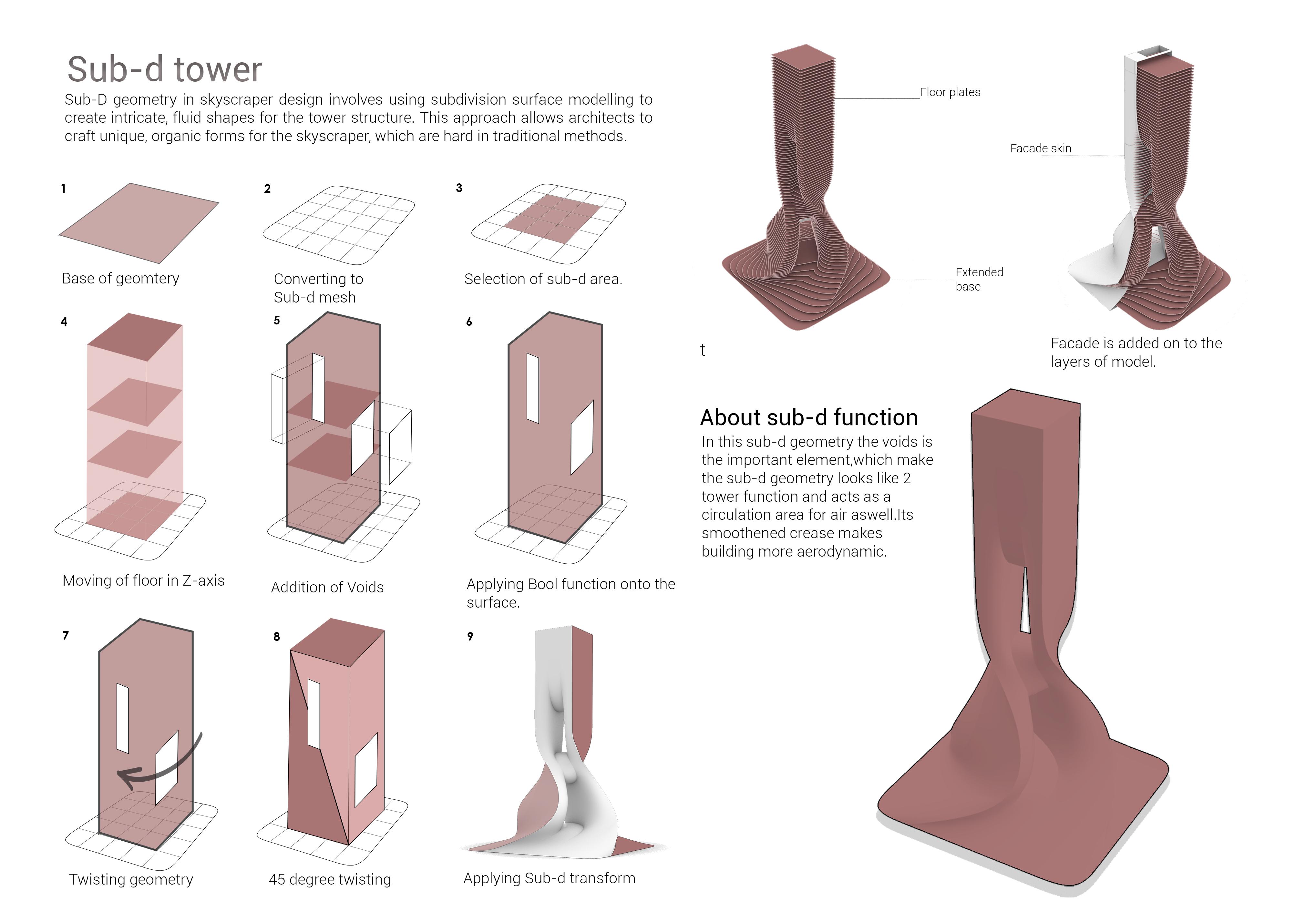
Sub-D Tower
Mesh Form Finding
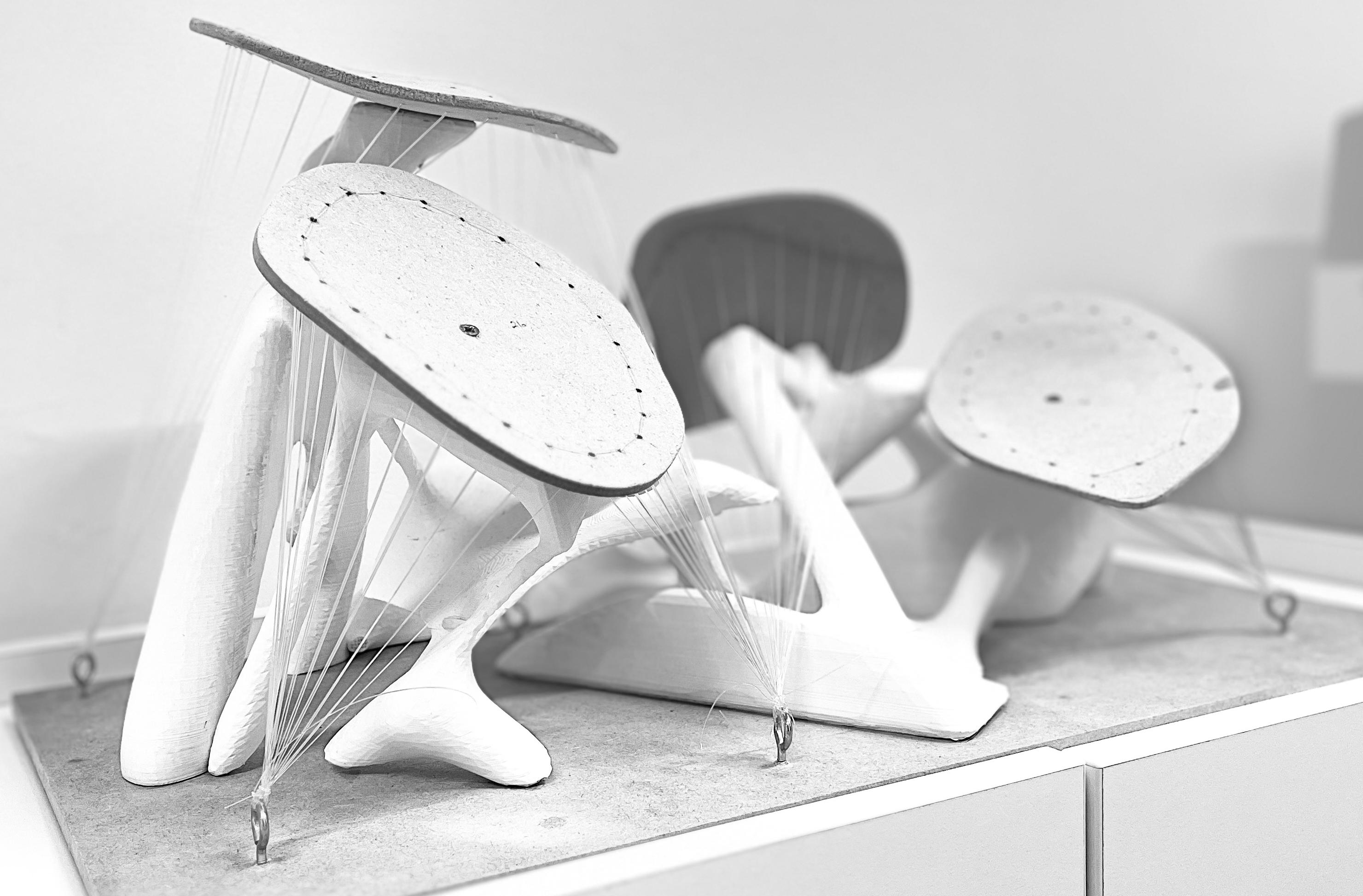
Anchor points
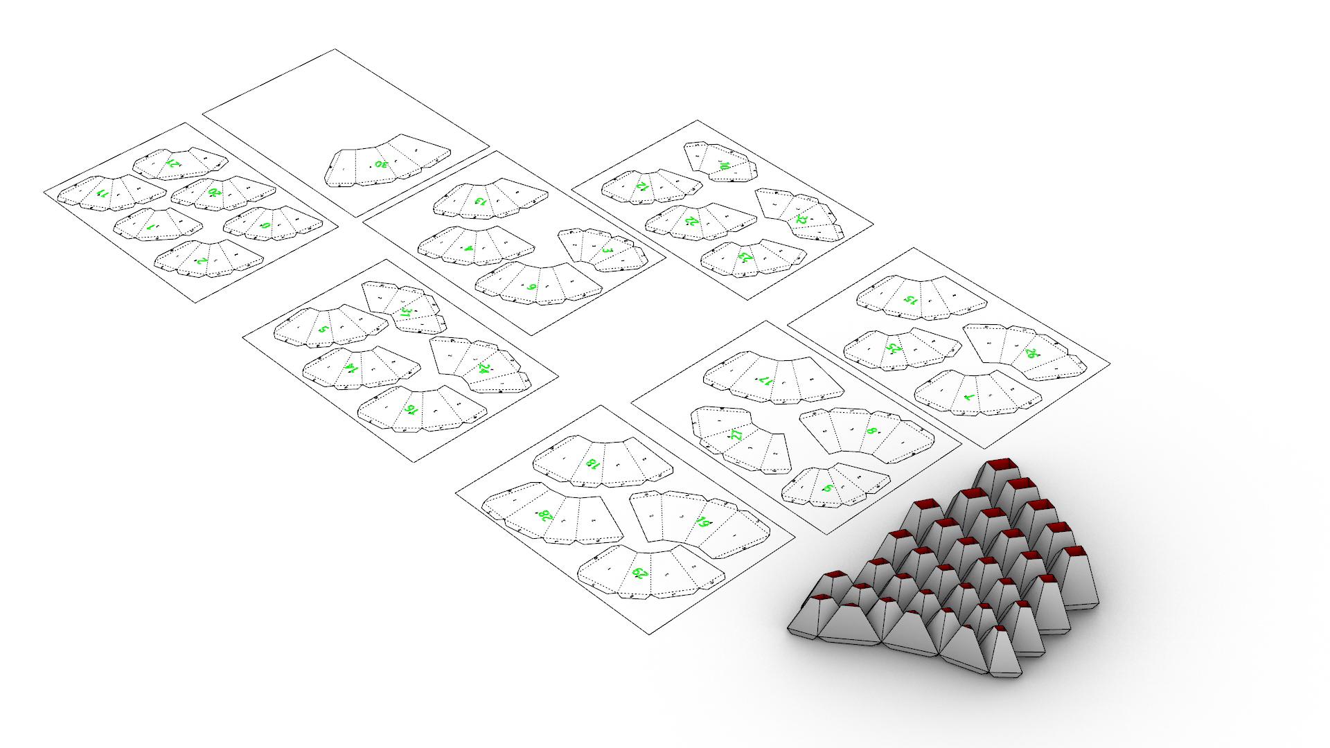
Component Segmentation: The image shows the overall structure on the left side, with detailed breakdowns of individual components on the right side. Each segment is numbered, indicating a modular design where each piece has a specific place in the overall assembly. The whole part of the structure got divided into parts and fabrication detail was organised in such a way that it should not make any hassel inbetween.
Automating geometry.
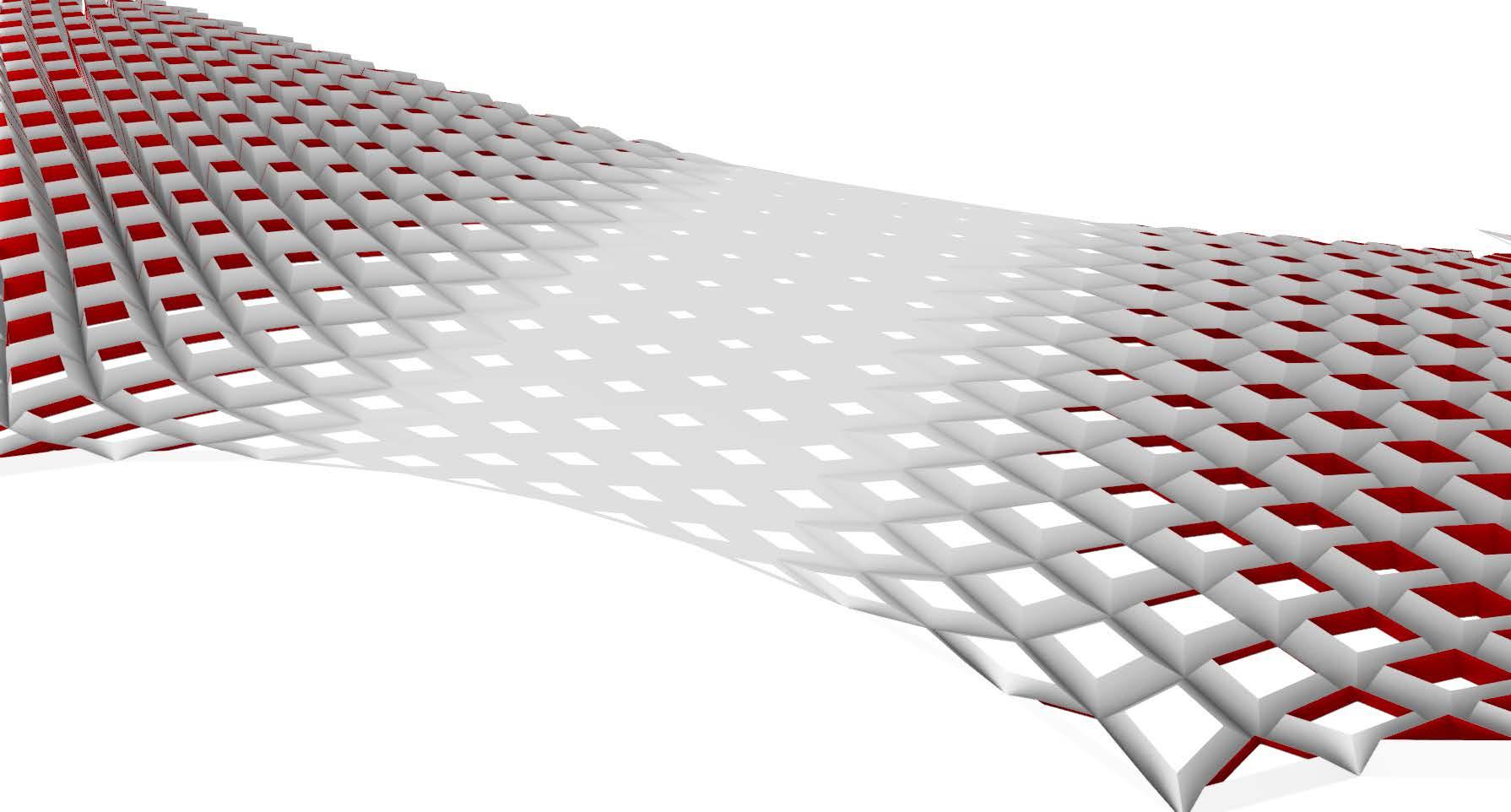
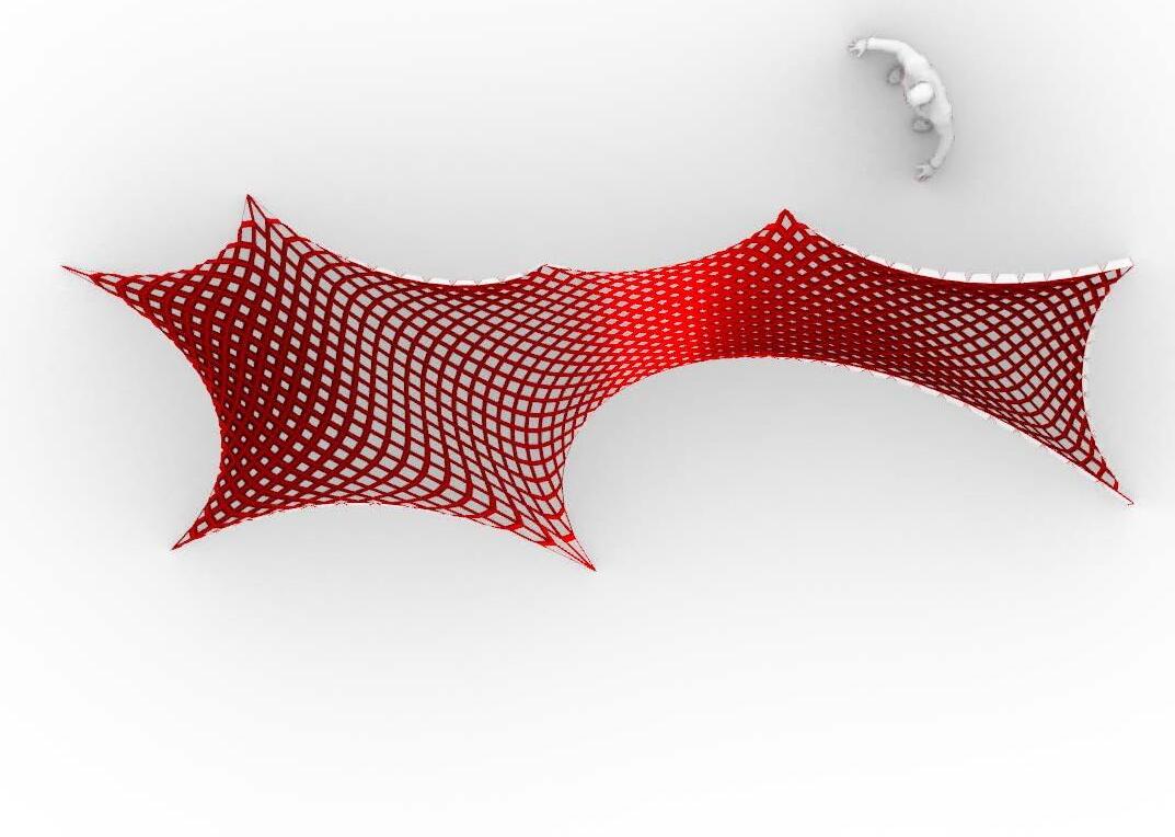
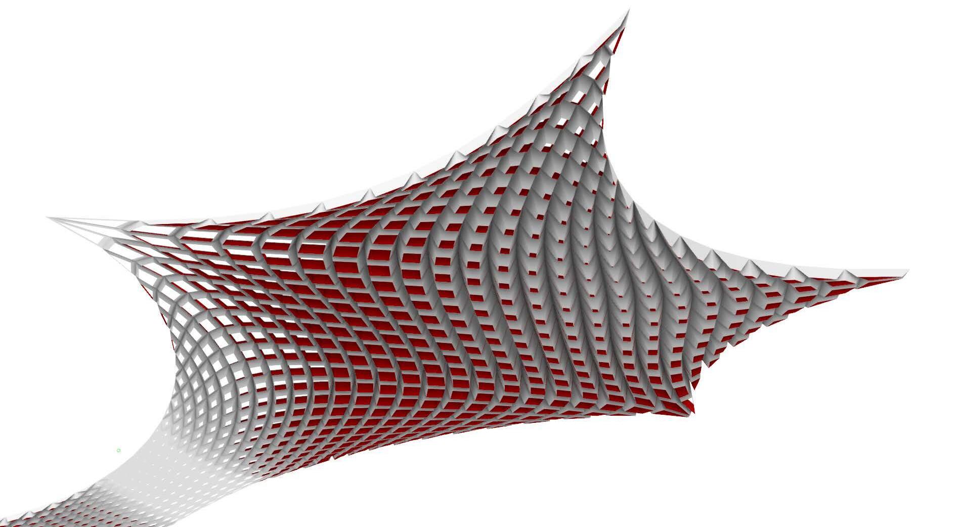
Form Generation: The form consists of a series of intersecting lines creating a grid pattern. The grid appears to be made up of repeating units, possibly rectangular or trapezoidal in shape, which are arranged in a curved, wave-like pattern.
Architectural Inspiration: This type of form is often seen in modern architecture and design, where complex geometries are used to create visually interesting and structurally efficient designs. It could be part of a roof structure, a façade, or a standalone sculptural element.
Potential Applications: Such a design could be applied in various fields, including architecture, civil engineering, and industrial design. It might be used for creating canopies, large-scale sculptures, or even in the design of lightweight structures that require both strength and aesthetic appeal.
Tensile Force
Tensile Force
Tensile Force
Tensile Force
Tensile Force
Tensile Force
Tensile Force
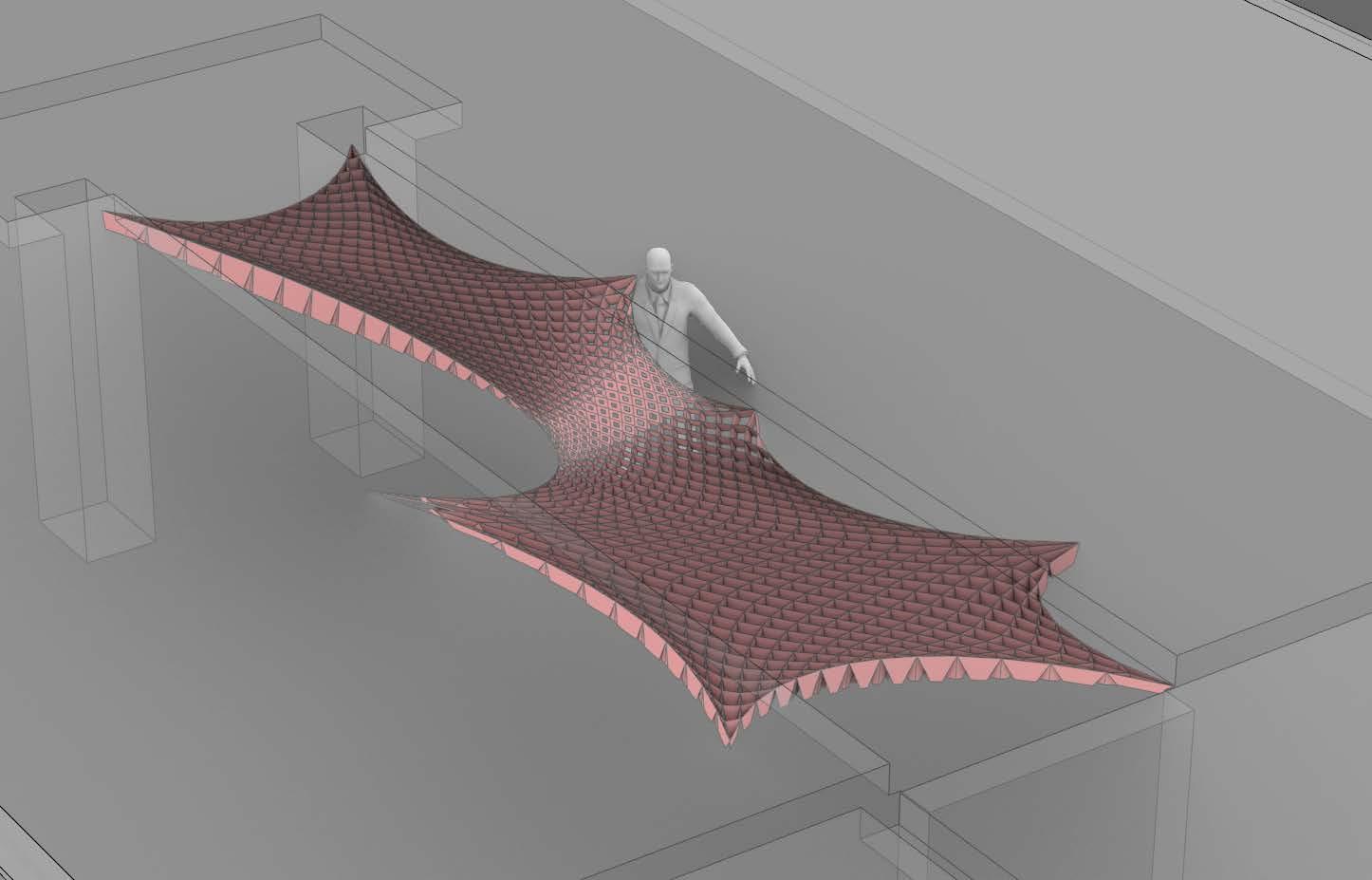
Simulation of mesh processing
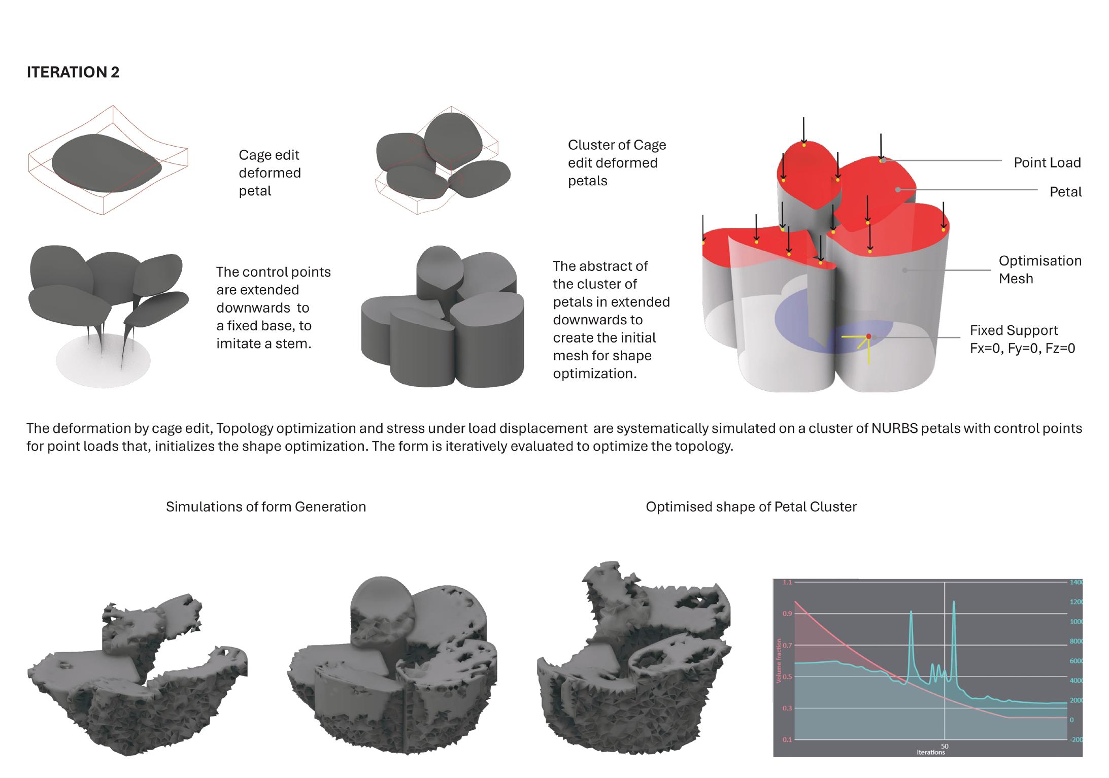
Creating the base geometry and editing the nurbs of the surface. Initialising the base arrangement. Giving the form the support. Then giving the load to the form which acts a on the support and the support will be optimised and will be rebuilt.
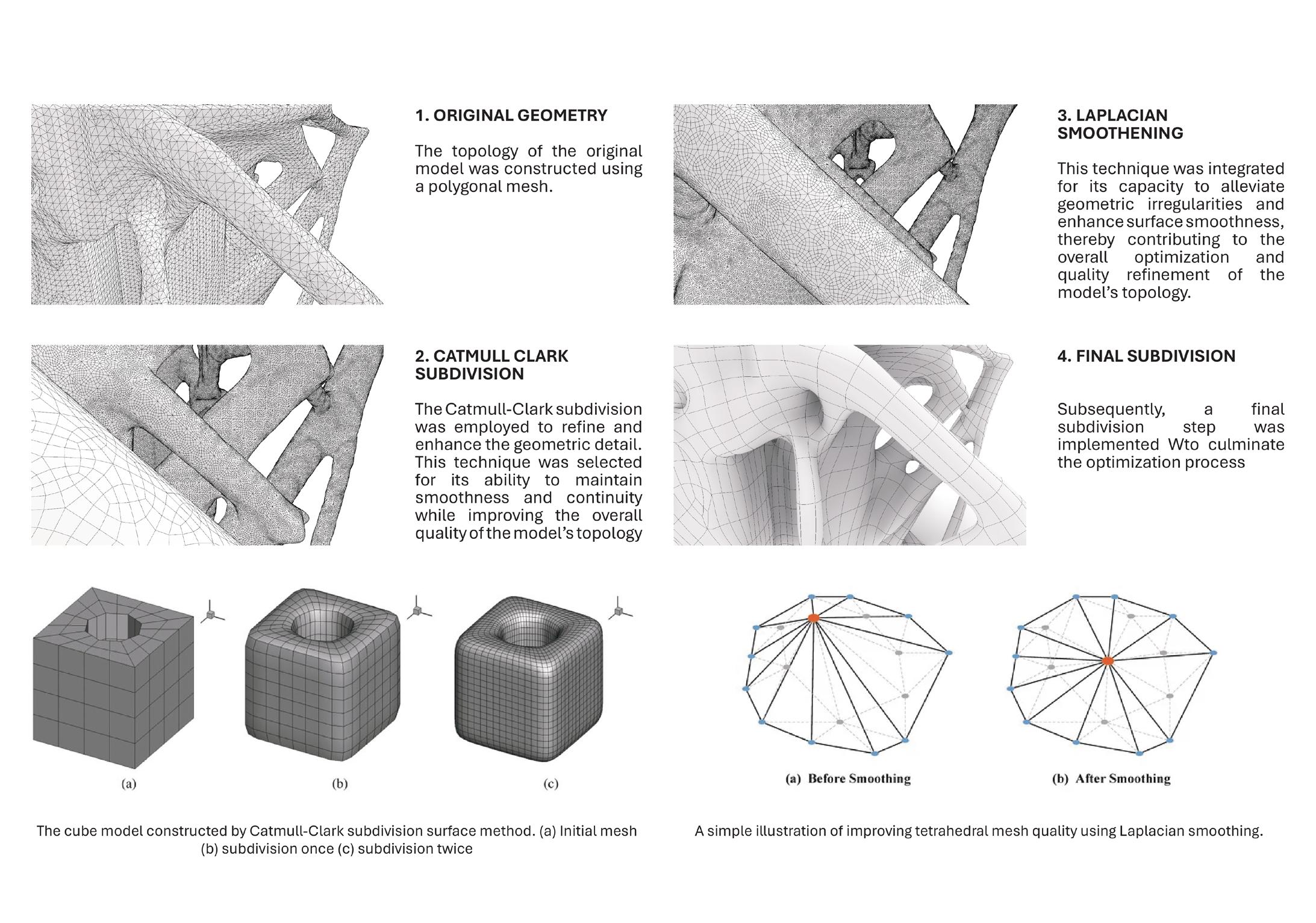
Application of different smoothening techniques:
Original Geometry:
Laplacian smoothenning:
Catamull clark SubD:
Final SubD:s
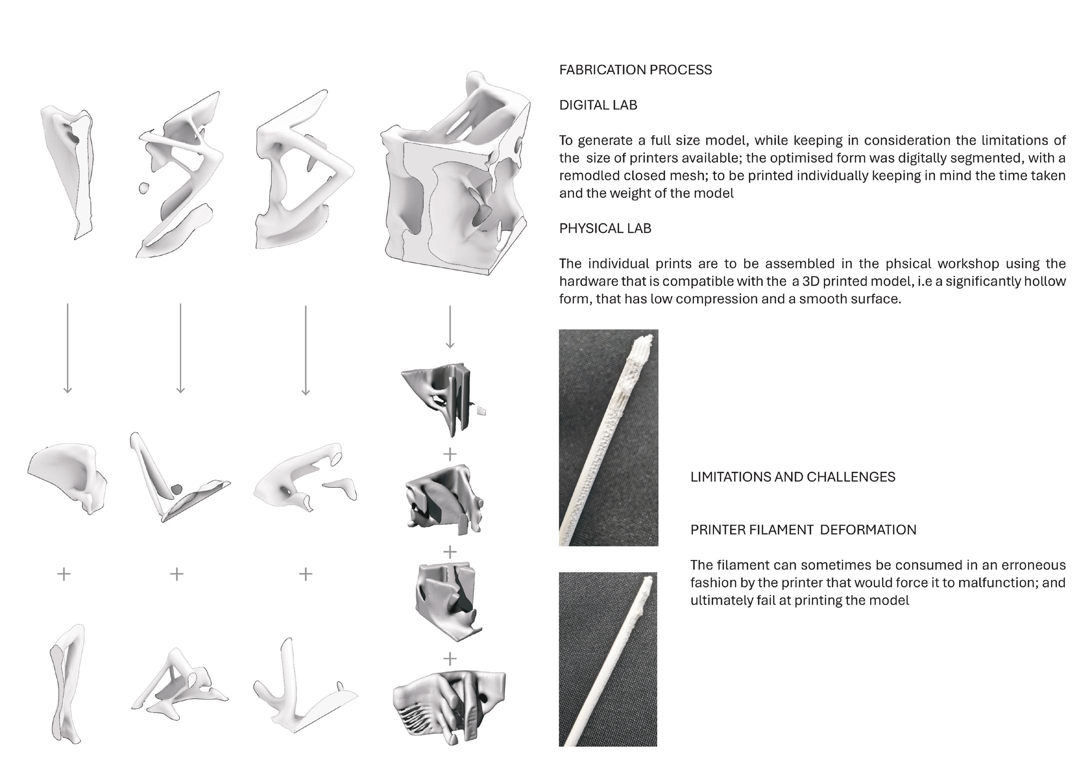
Fabrication Process:
The simulation of the mesh that gives the optimised mesh and the model is to be deconstructed to the possible fragments and to be assembled as a sculpture.
Fabrication Process:
While fabricating the model the infill of the mesh has been constructe in a multiple way where as the filaments has a infill of 40% and 80% to classify the strength capability.
Genetic Algorithm
Process of evaluating the facade:
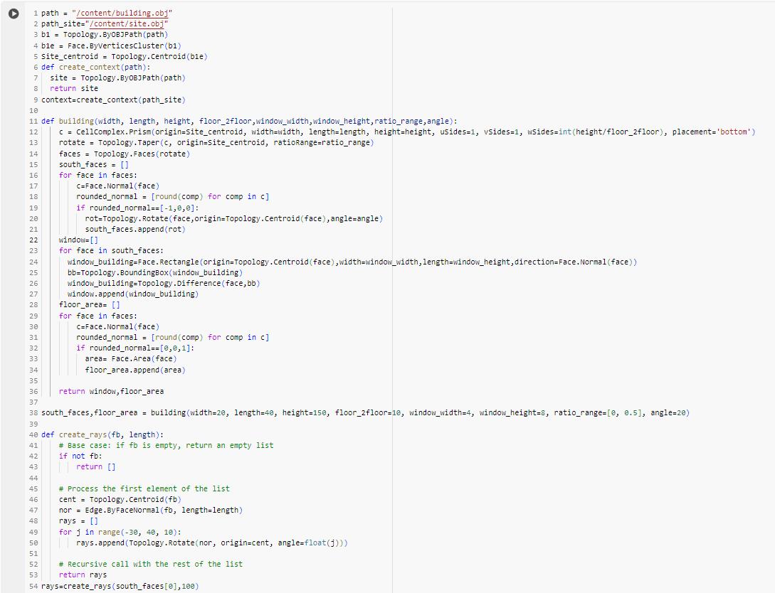
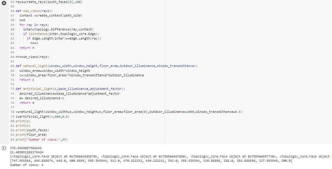
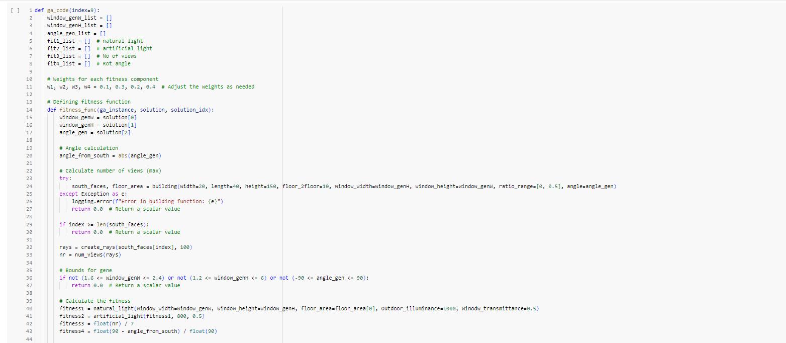
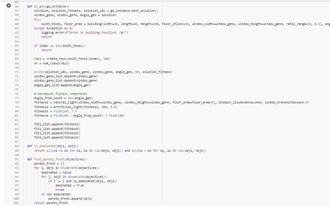
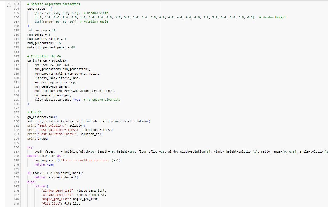
This sheet outlines a computational method for optimizing building design using a genetic algorithm with the Pygad library, applied to a site context in Virginia, USA. The process involves importing the Virginia site context, creating a building model, and calculating views and light using rays. The genetic algorithm optimizes the building’s shape and orientation to maximize the fitness function, which considers factors like light exposure and view quality, ensuring the best design solution for the specific site.
Python Code
Pseudocode
“Initialize Parameters”
“Load Building and Site Data”
“Create Context”
“Define Building Function”
“Generate Building”
“Define Rays Creation Function”
“Create Rays”
“Define Number of Views Calculation”
“Calculate Number of Views”
“Light Calculation” :
“Artificial Light Calculation”
“Calculate Light”
“Genetic Algorithm for Optimization”
“Run Genetic Algorithm”
“Print Final Results”
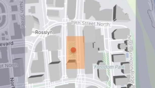
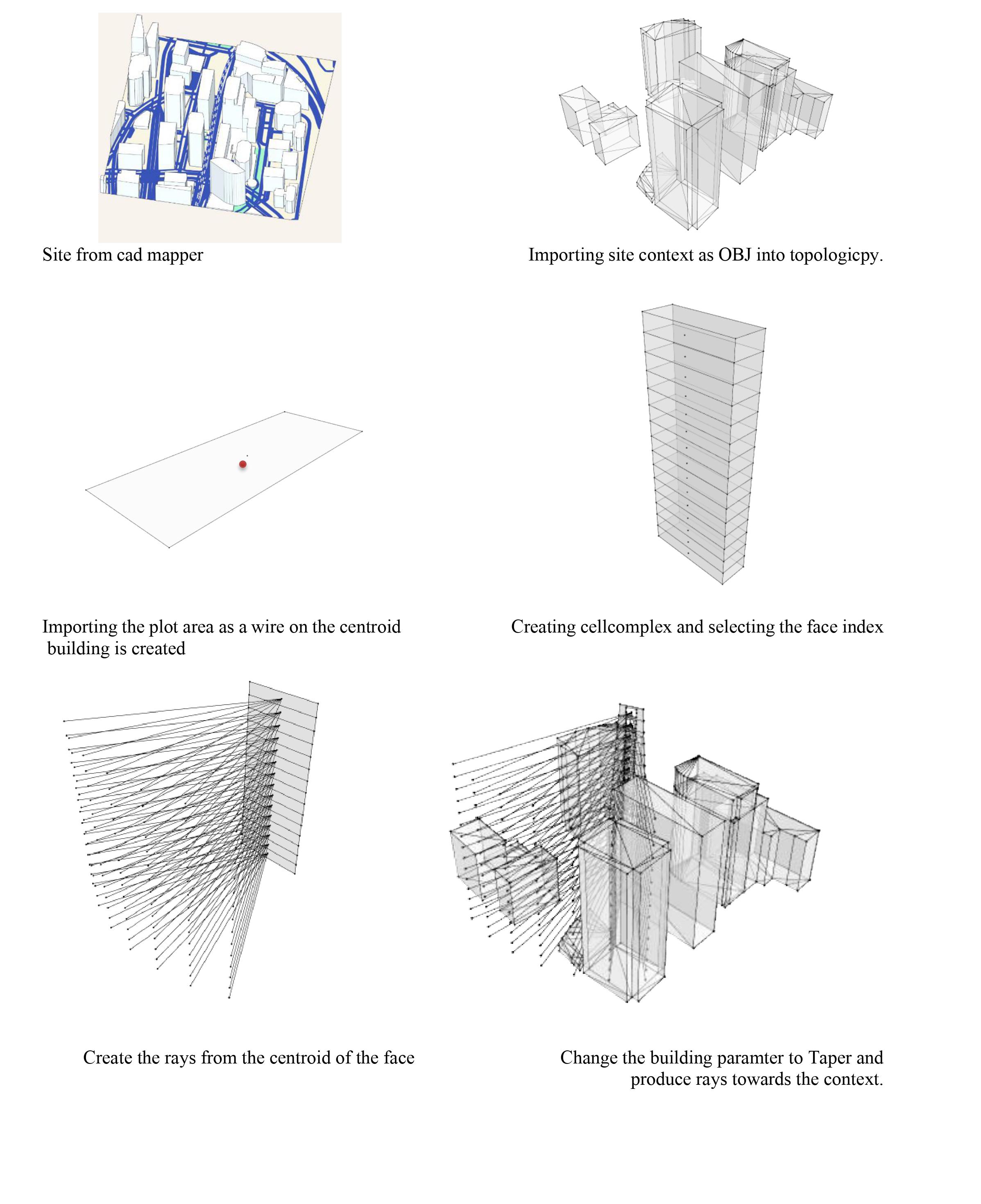
Creating site context from cad mapper.
Importing Site Context as OBJ file in to topologicpy
Importing the plot area as a wire and create a centroid to create building
Creating CellComplex and selecting the face index of the cell.
As per fitness function rays been created from the faces and casted on the neighbourhood.
Genes been created so the building is scaled up and faces of the building is rotated to maximize the fitness function.
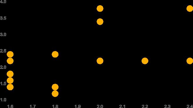
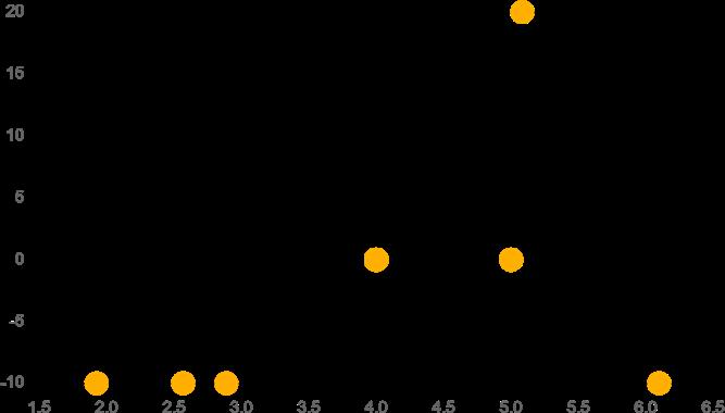
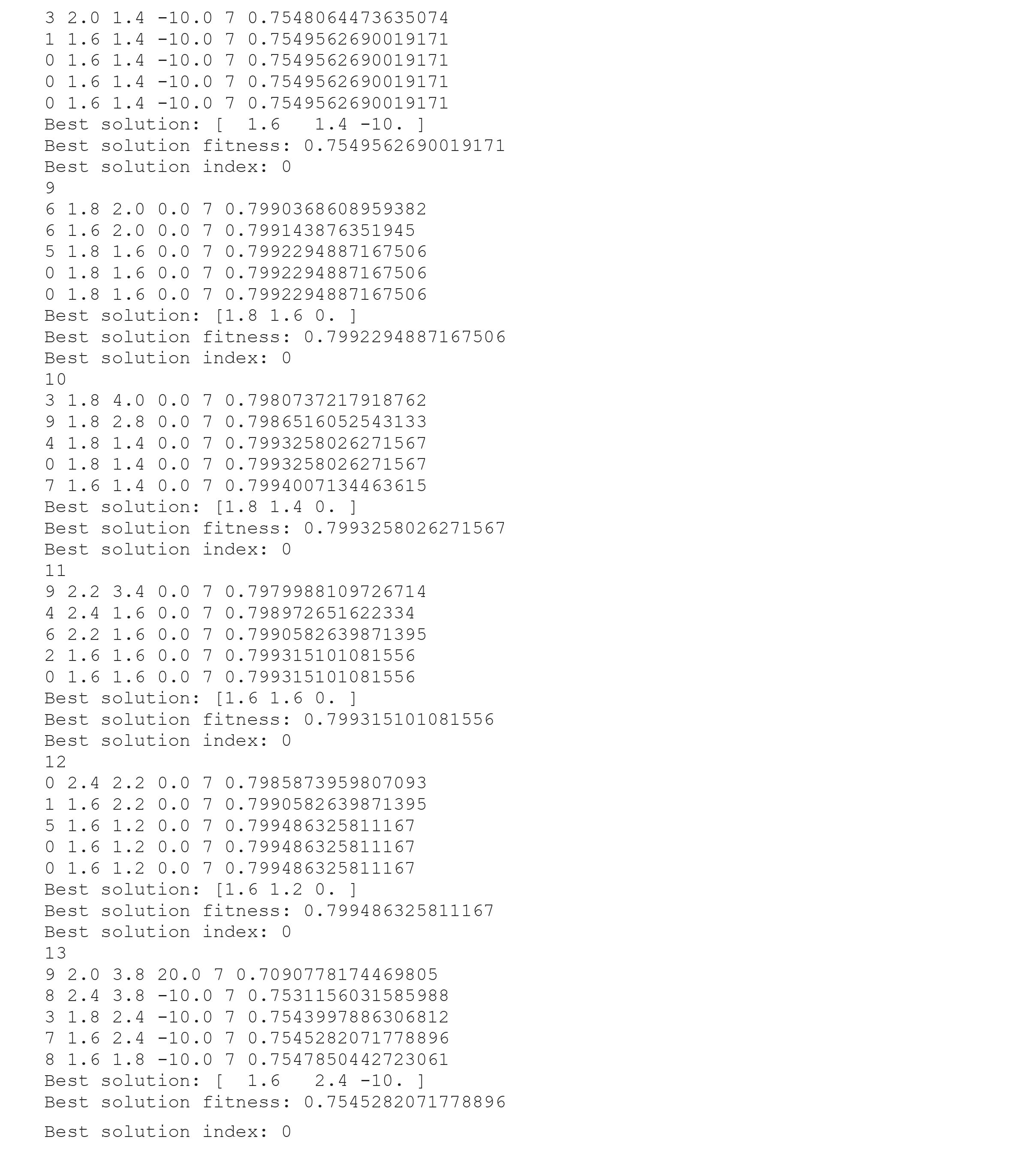
Optimized Solutions from Computational Evaluation:
These results showcase the best solutions derived from computational evaluations using the fitness function. Each line represents a set of parameters, such as dimensions and angles, optimized to achieve the highest fitness score. The genetic algorithm iterated through multiple generations, adjusting parameters to maximize factors like light exposure and view quality. The scatter plots visually represent the distribution of solutions, highlighting the most effective configurations. The final best solutions demonstrate the effectiveness of computational methods in architectural design optimization.
Pareto front Analysis
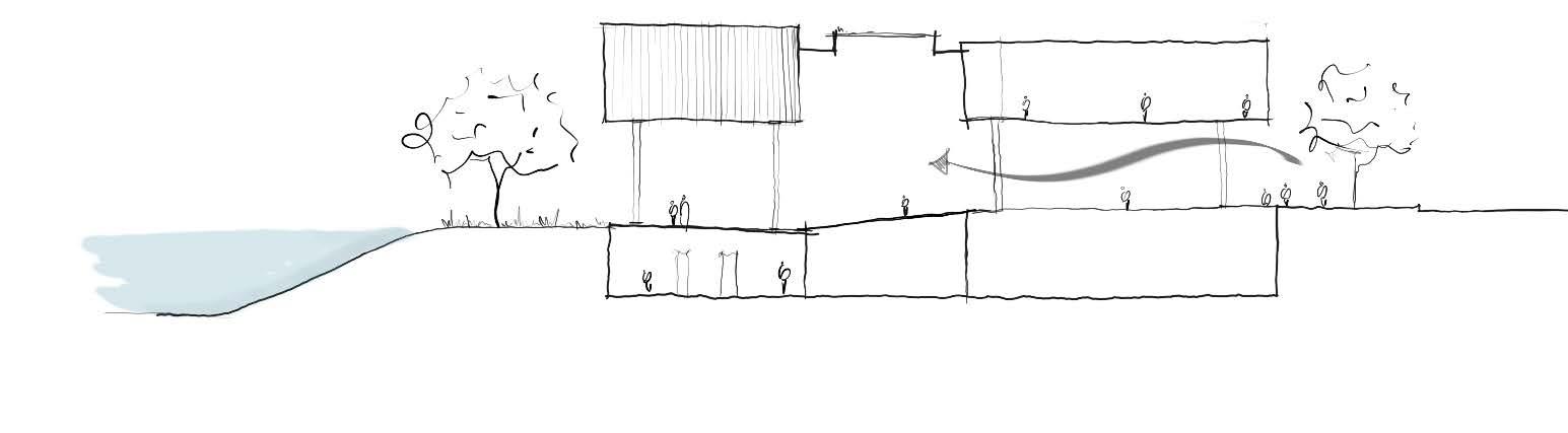
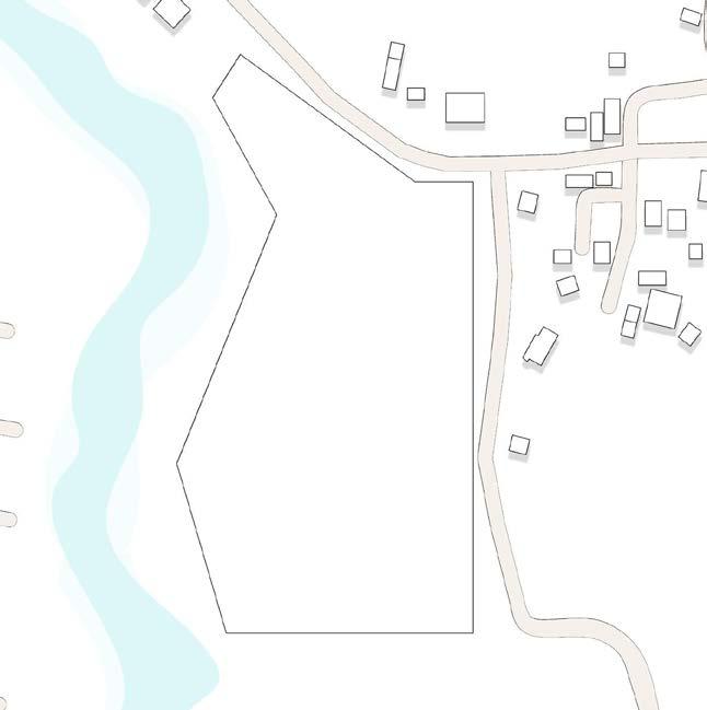
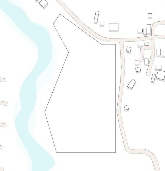
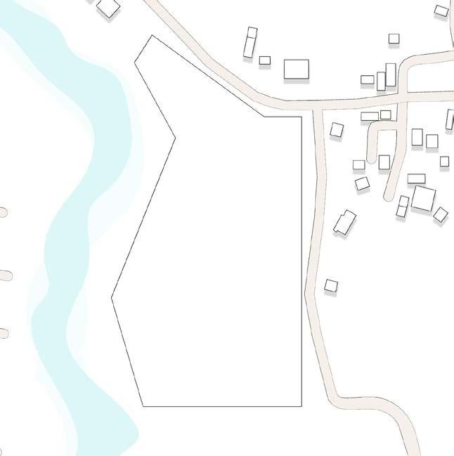
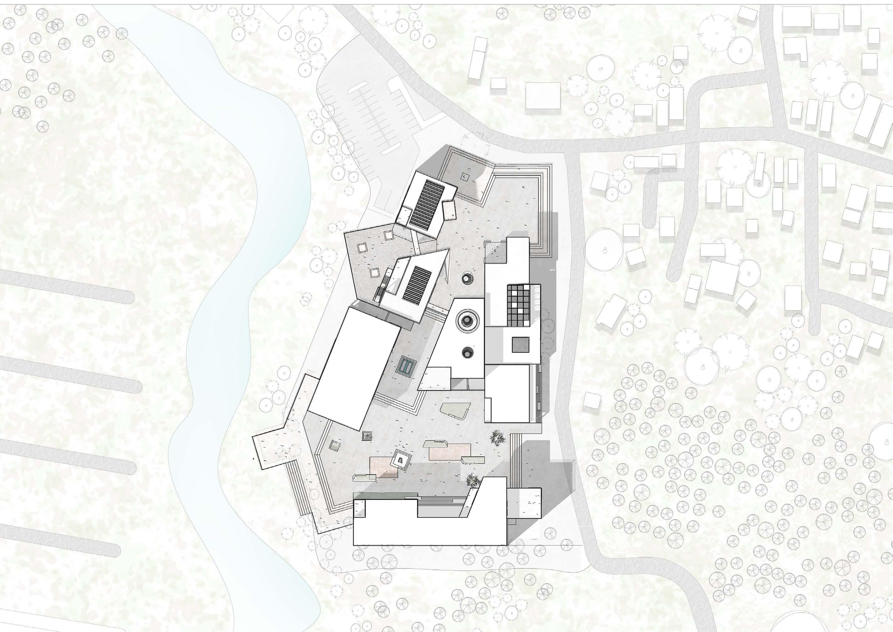
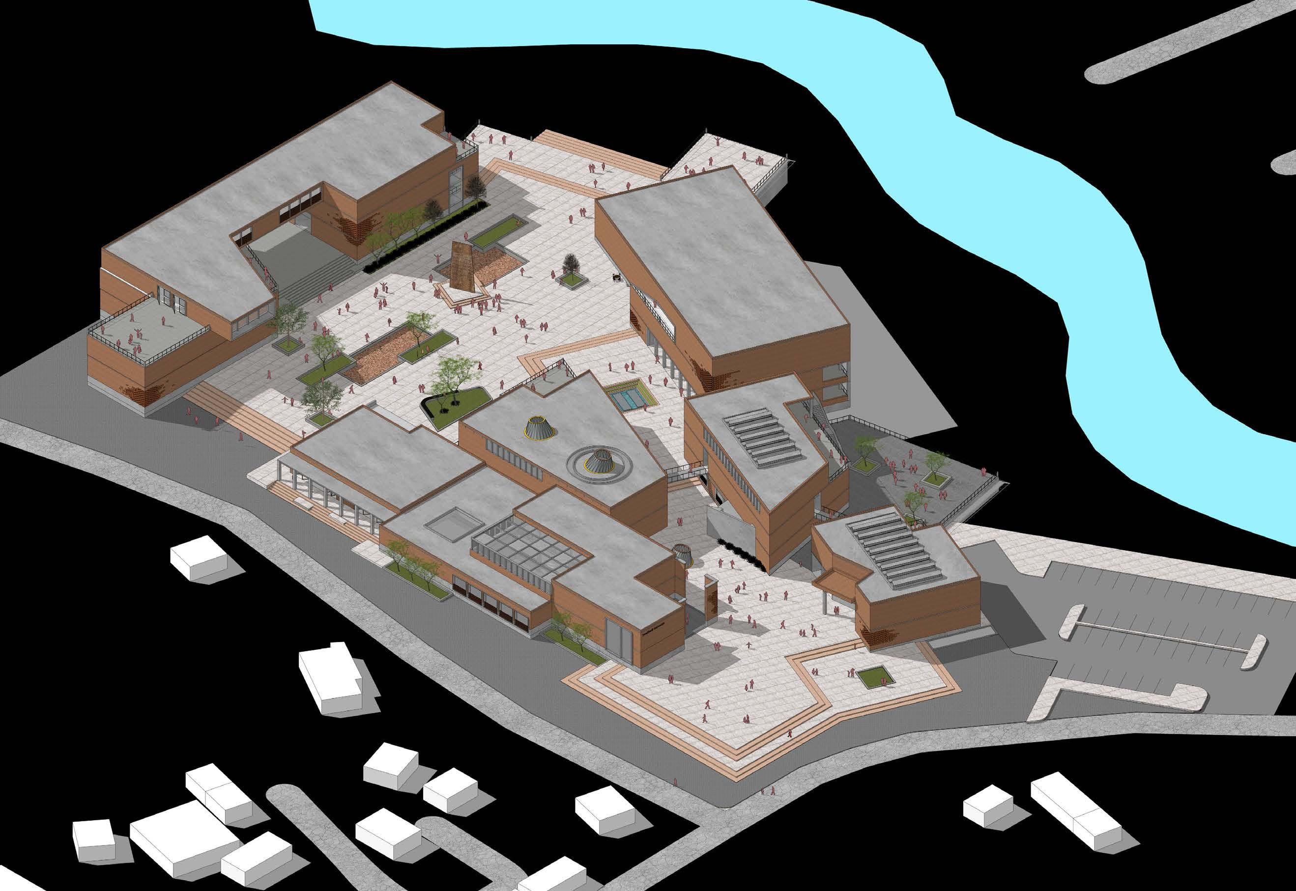
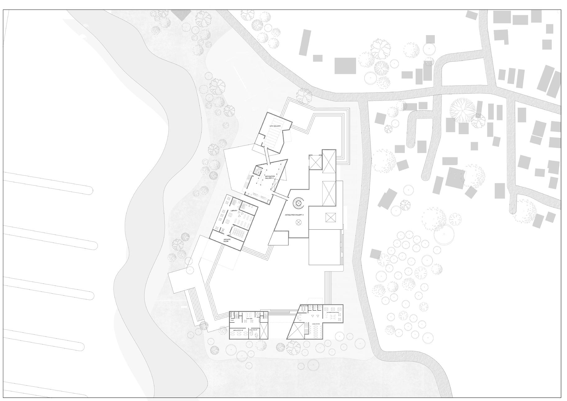
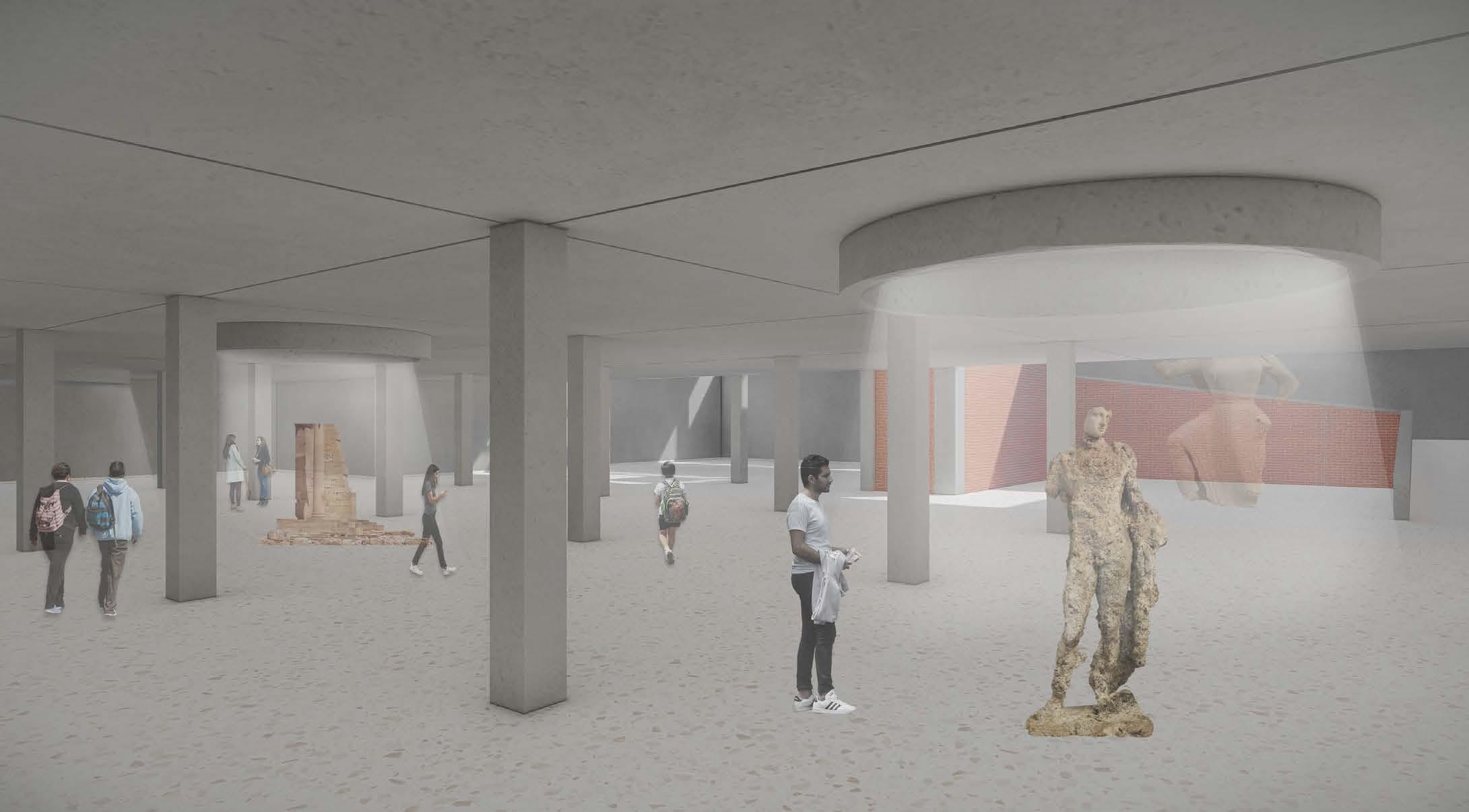
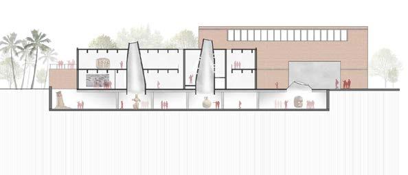
Museum Proposal
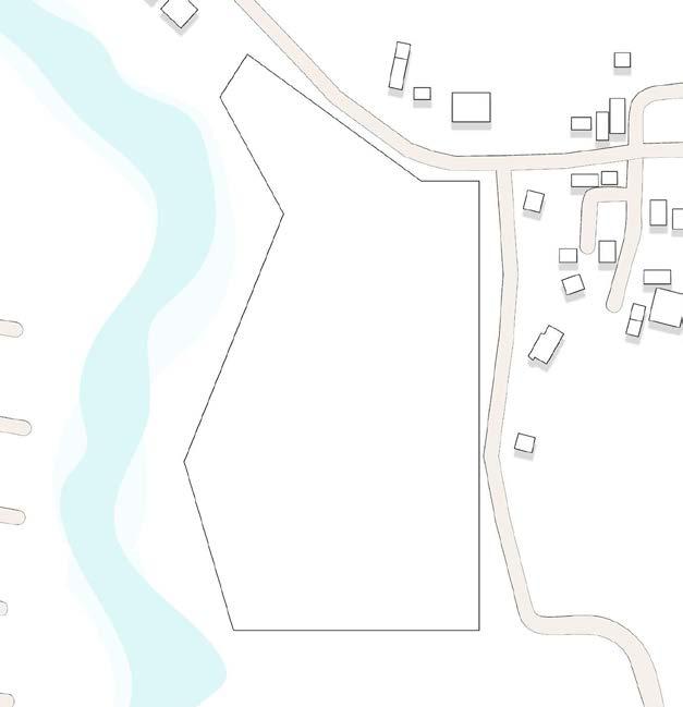
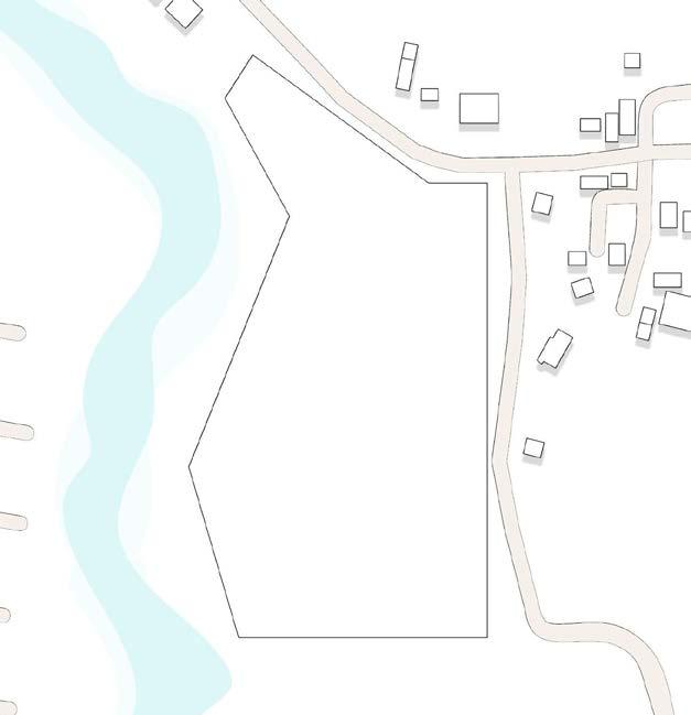
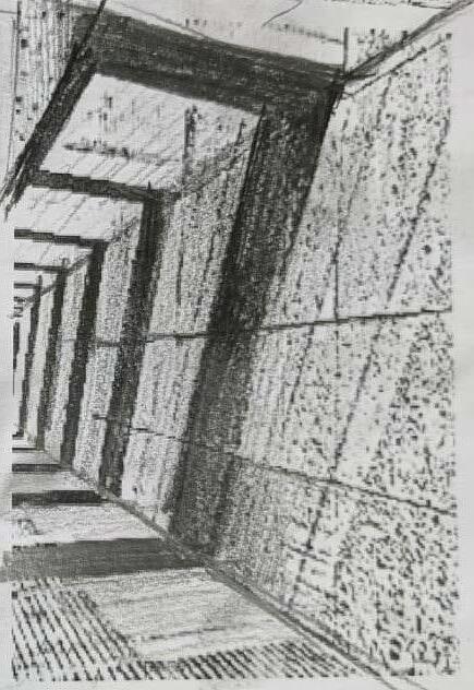
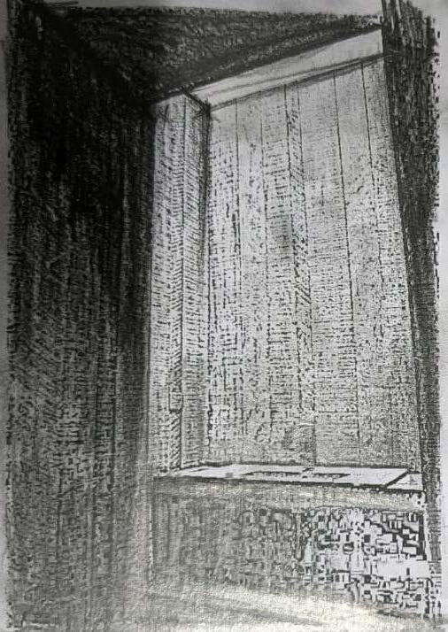
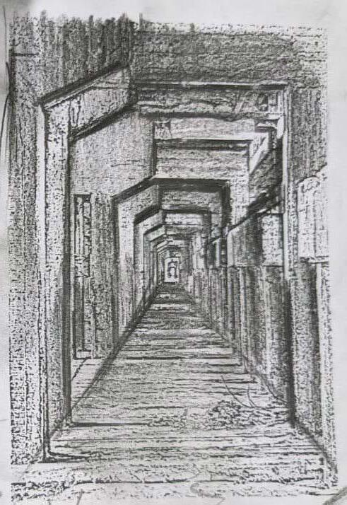
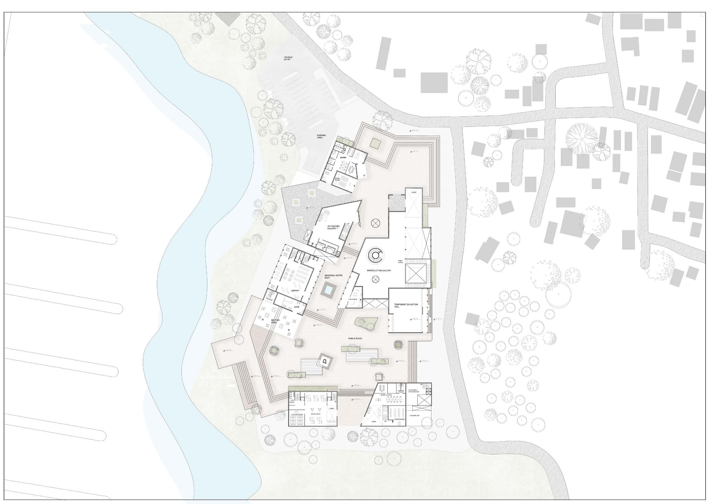
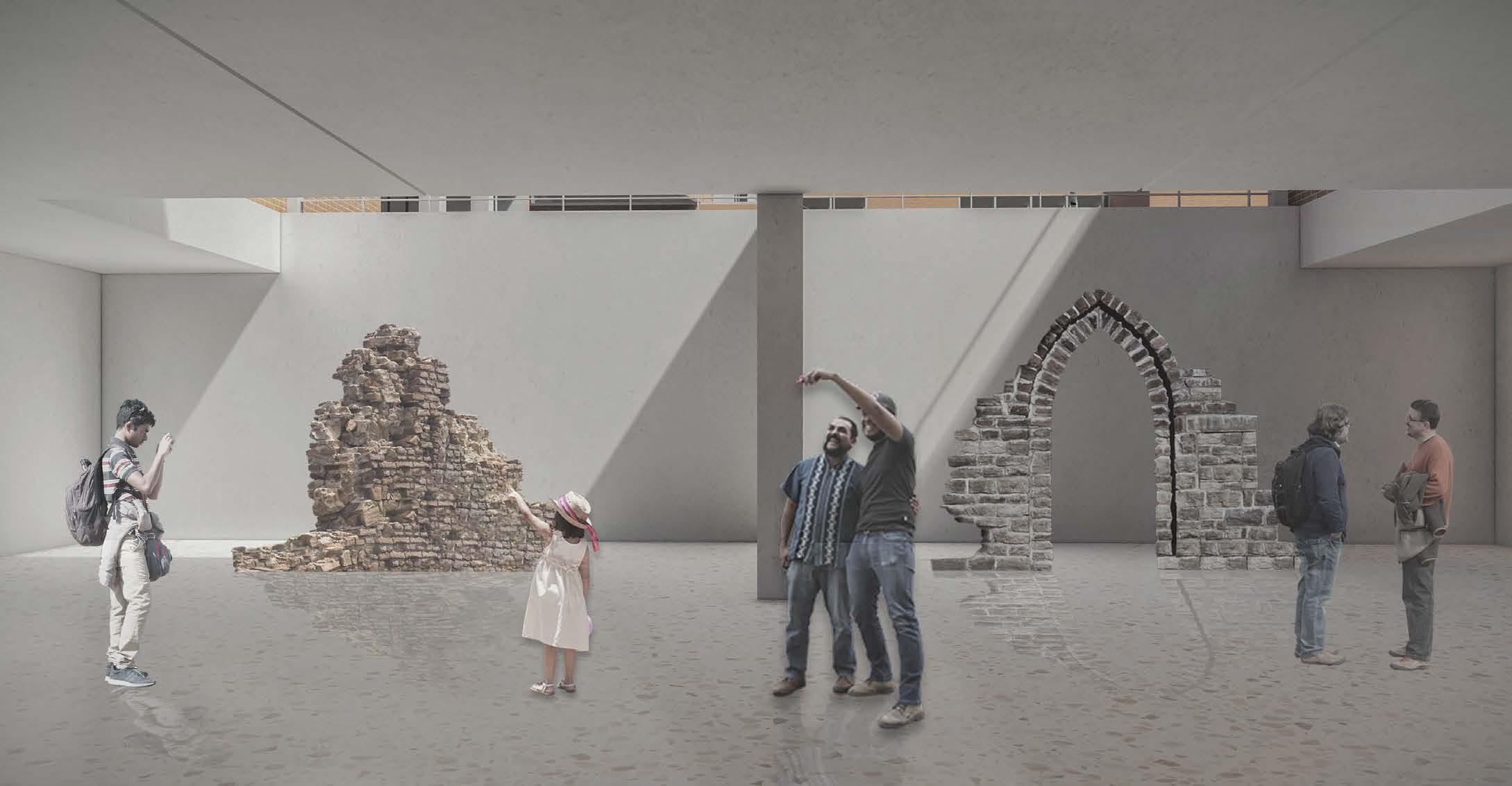
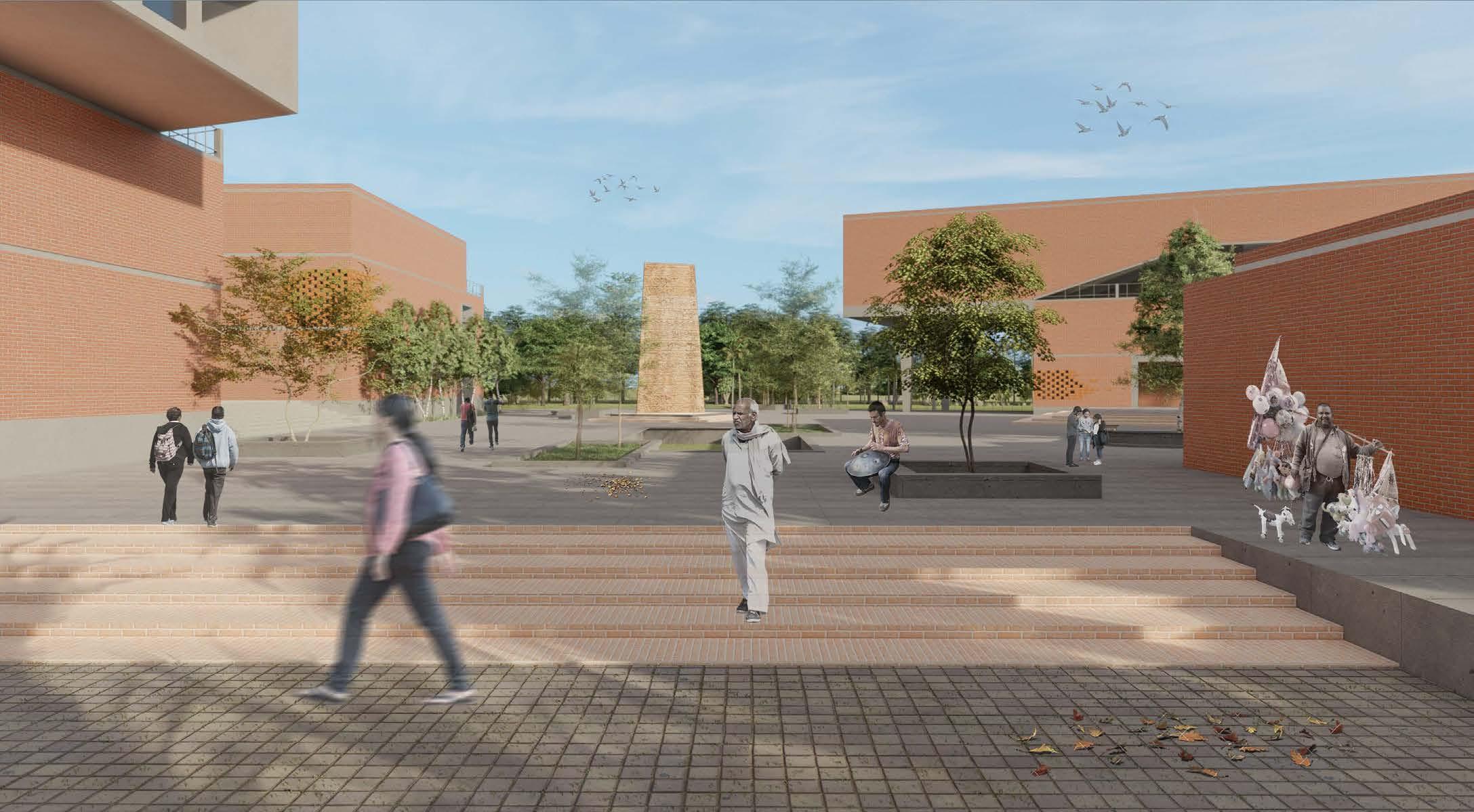
Looking at the excavation grid and using the base in an indirect manner enables the user to have a disconnect from the physical structure and would give the feel of being within the excavation or taking back to the past and giving the liveliness is the overall language of the main core idea.
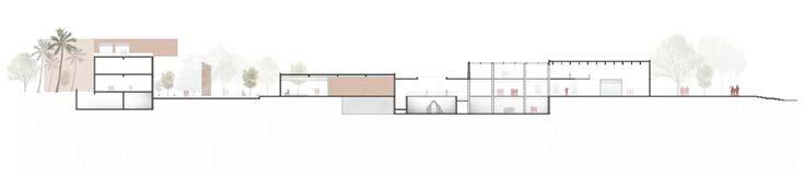
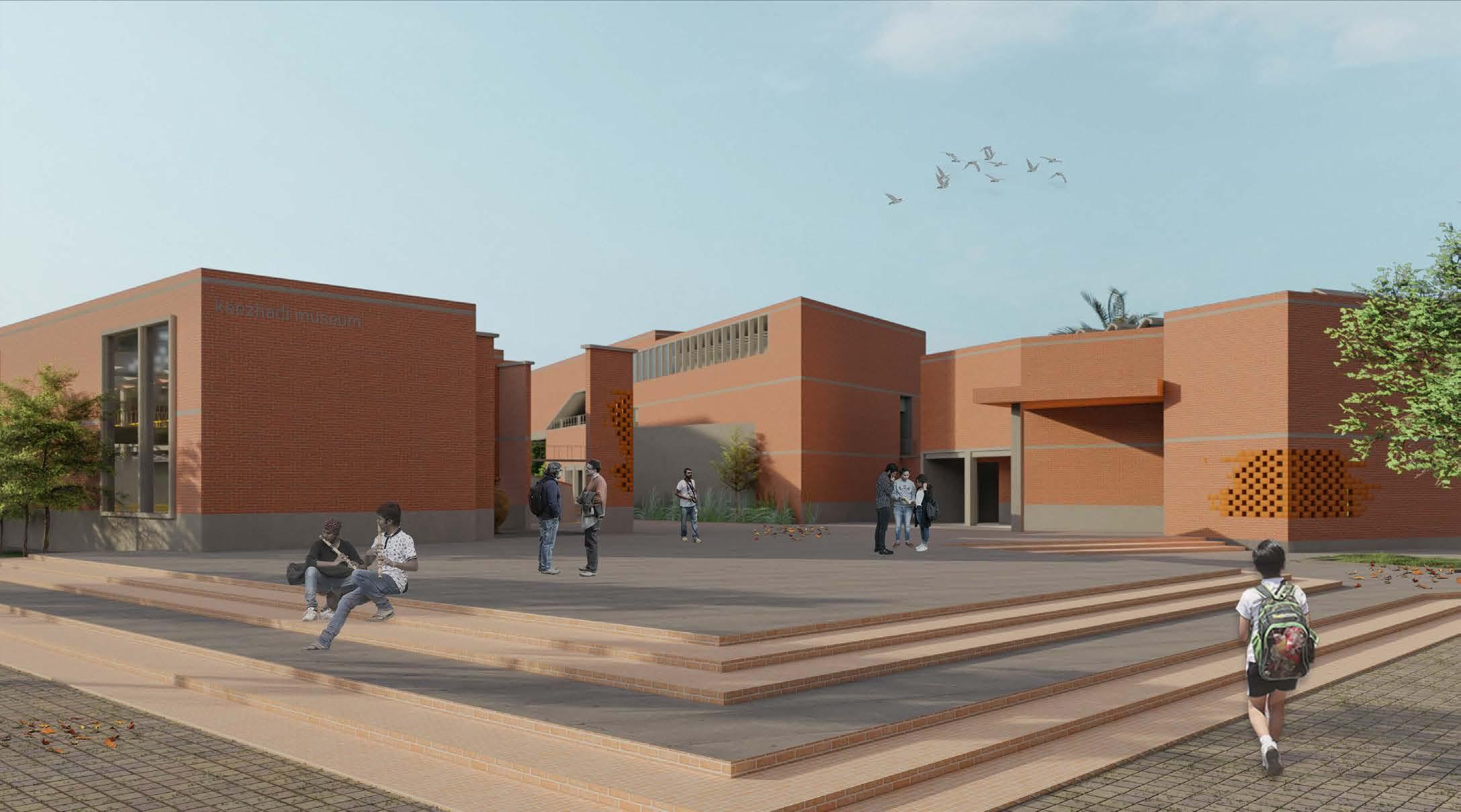
In doing this, I’m also clear that the building should well blend with the landscape rather than being in contrast with it.
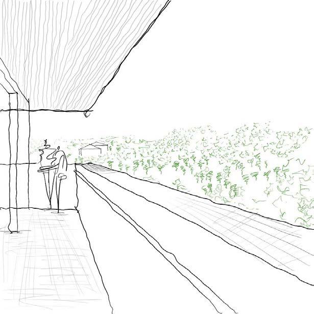
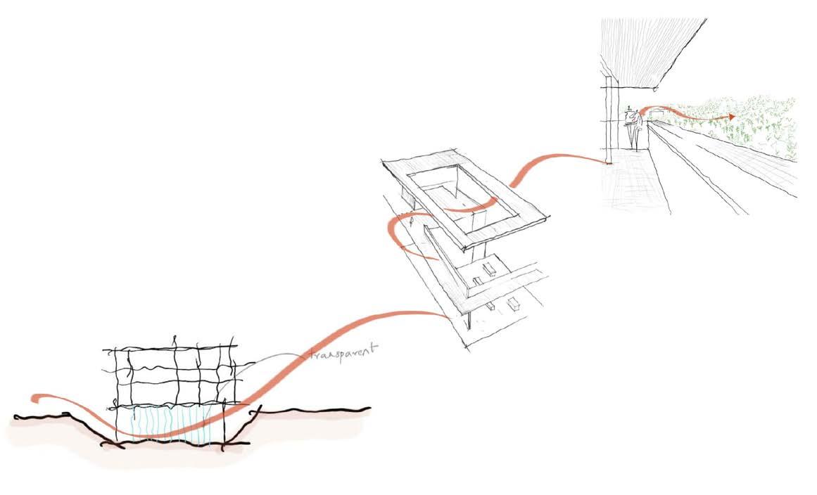
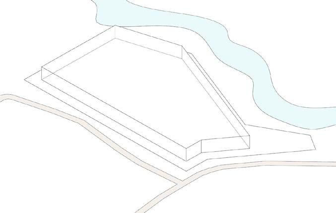
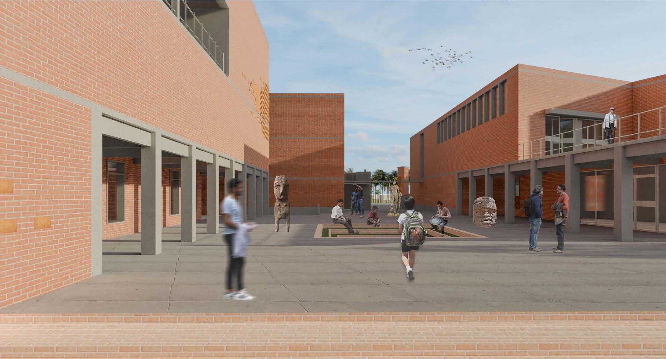
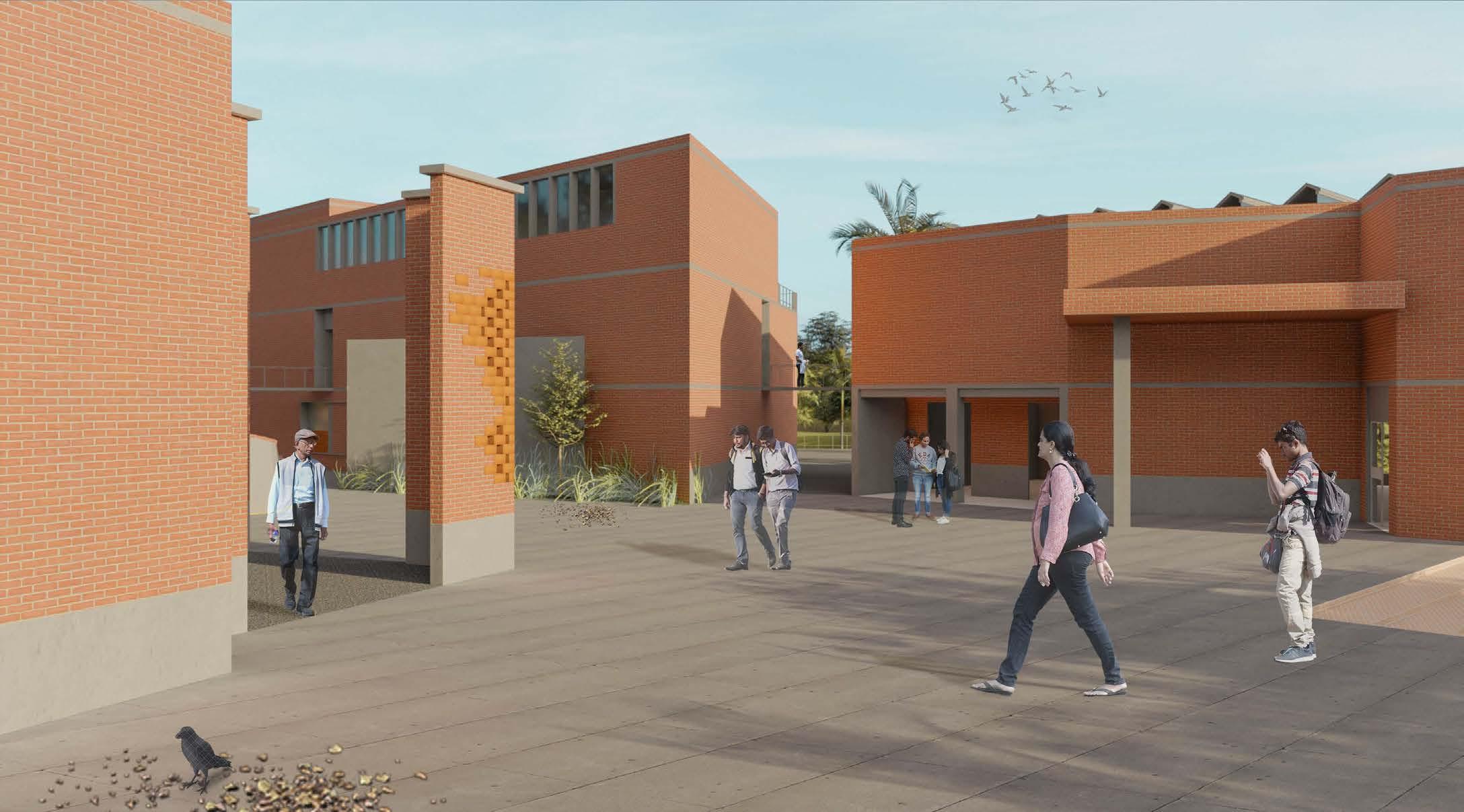
Introducing viewing decks in the building because all the hamlets around the site are mostly ground floor and the immediate landscape of the site is surrounded by coconut groves and farmlands and water drains. Also, this would give the users the connect of the excavations at various parts nearby.
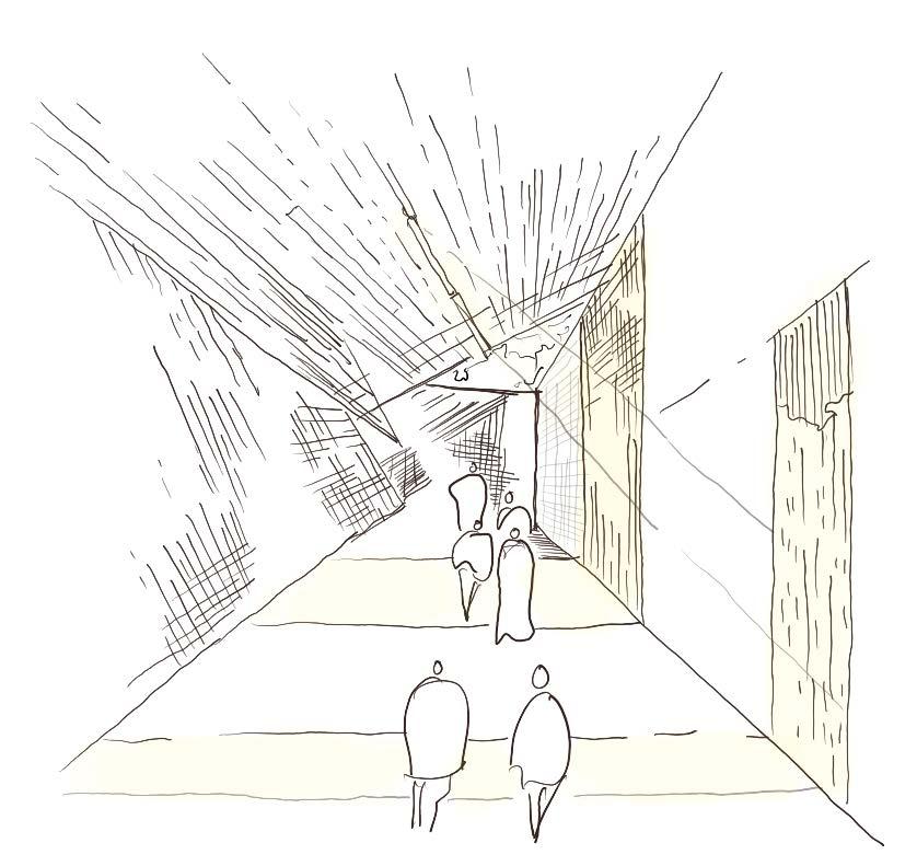
Some exhibition spaces would be black boxes. The transition space between one museum to another would have an outside connect such as inducing natural light.
To create visual connectivity from the roadside edge to the opposite river edge. This is a semi-open space that is invitable also an extension of public spaces.
This central plaza ties both private and public spaces and also it isn’t just for museum visitors but open for all common people thus being a recreational space.
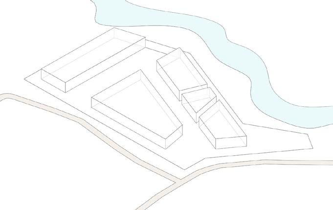
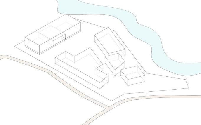
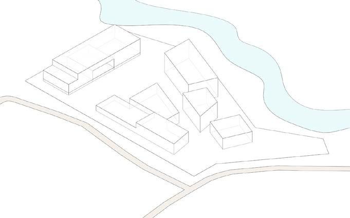
DESIGN STRATEGIES
& 10m
CONCEPTUAL IDEAS
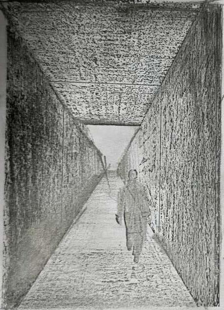
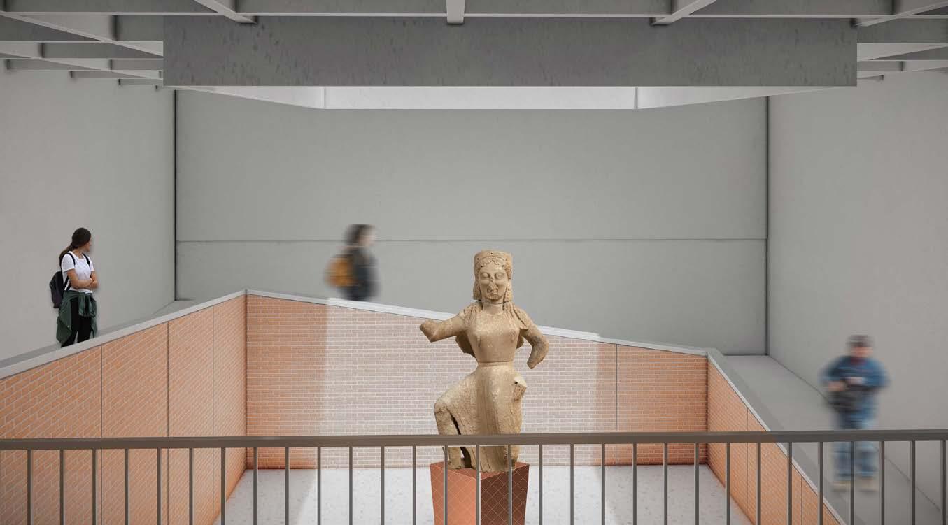
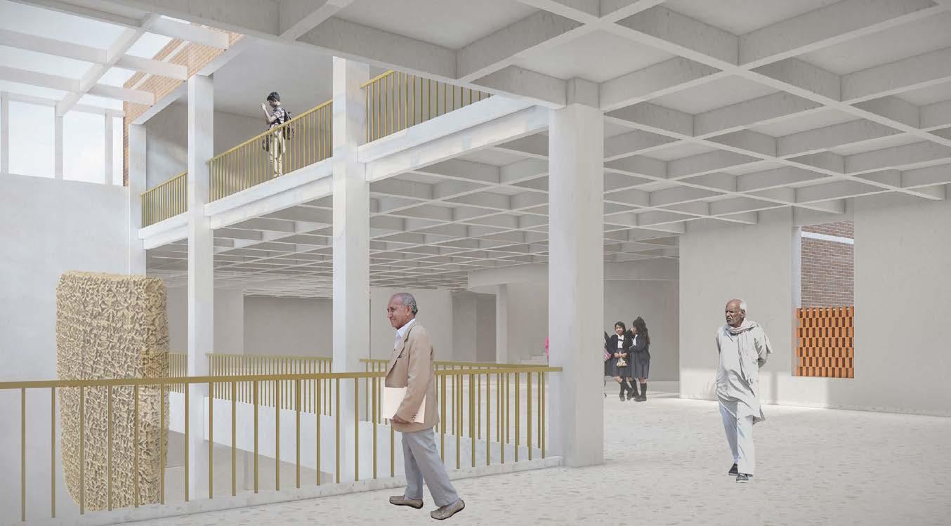
When the users go level down gives them the earthy feel and when the user is above, onlooking the site gives them the feel of looking into the excavation pits.
The journey ends in the viewing decks thus drawing parallels with the Keezhadi village.
DESIGN DEVELOPMENT
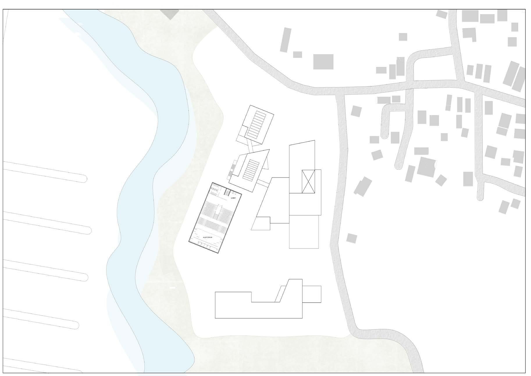
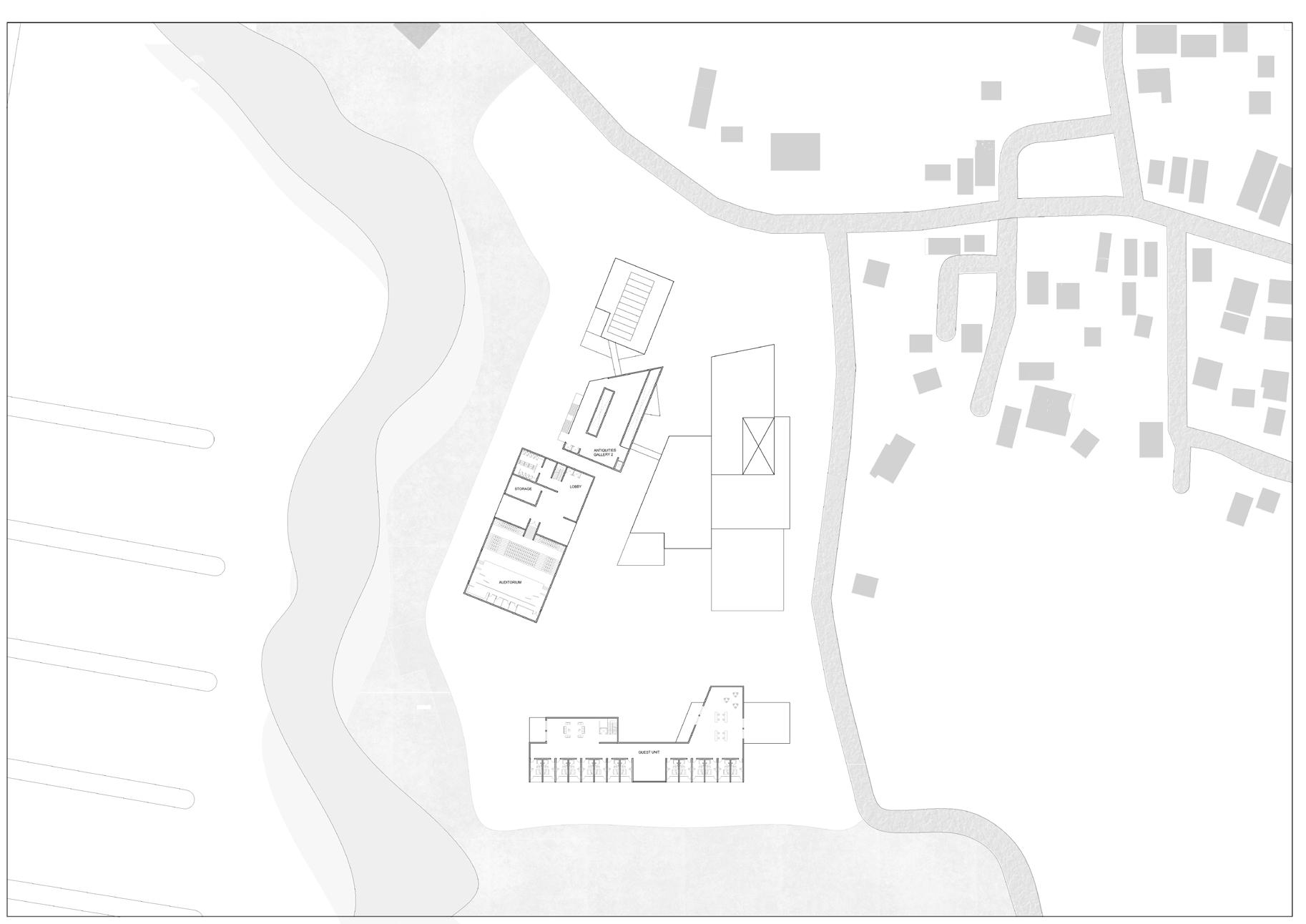
Masterplan
view of the ramp
view of the introdcution gallery
view of the antiquities gallery 1
view of the antiquities gallery
view of the sunken courtyard
view of the entrance plaza
view towards the stream
view of the public plaza
Model: Rhino & grasshopper
Postproduction: Adobe PS & ID
2D drawings: Autocad
Visualization:Enscape
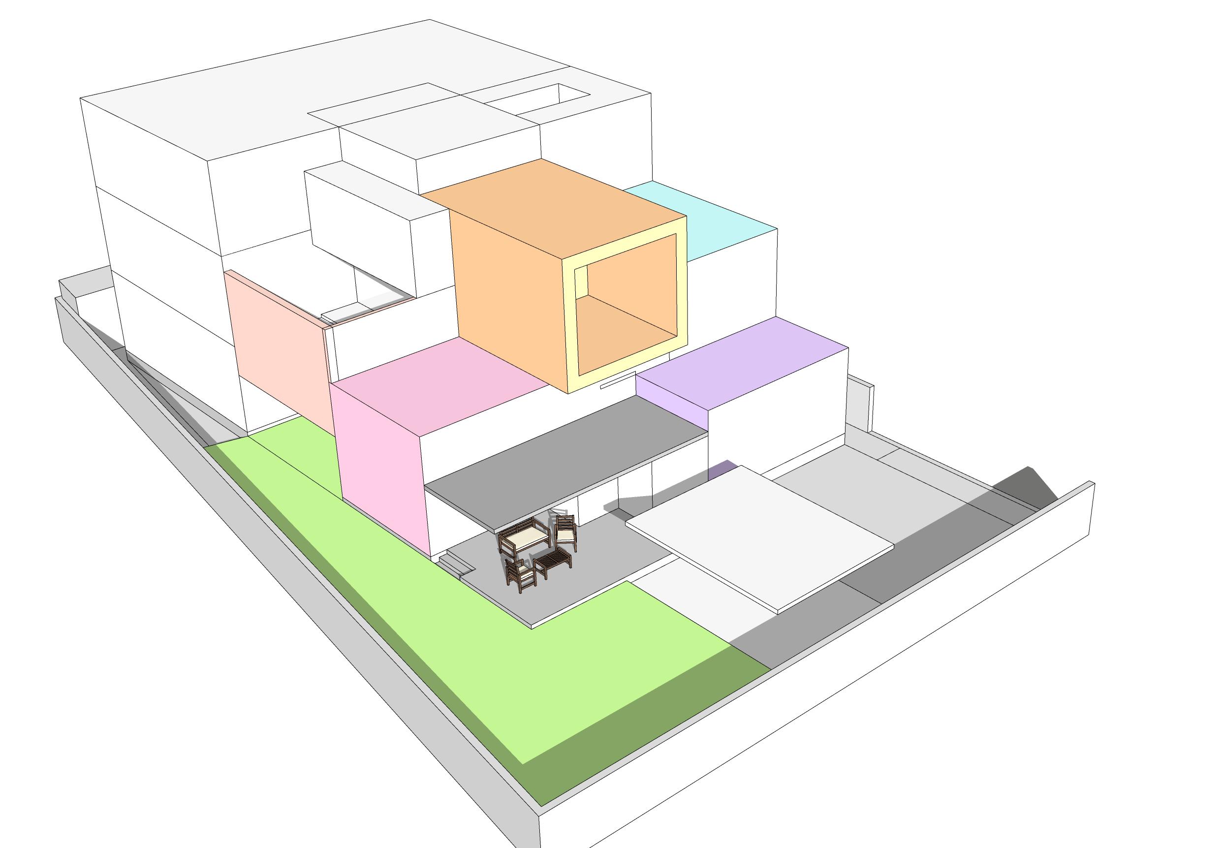
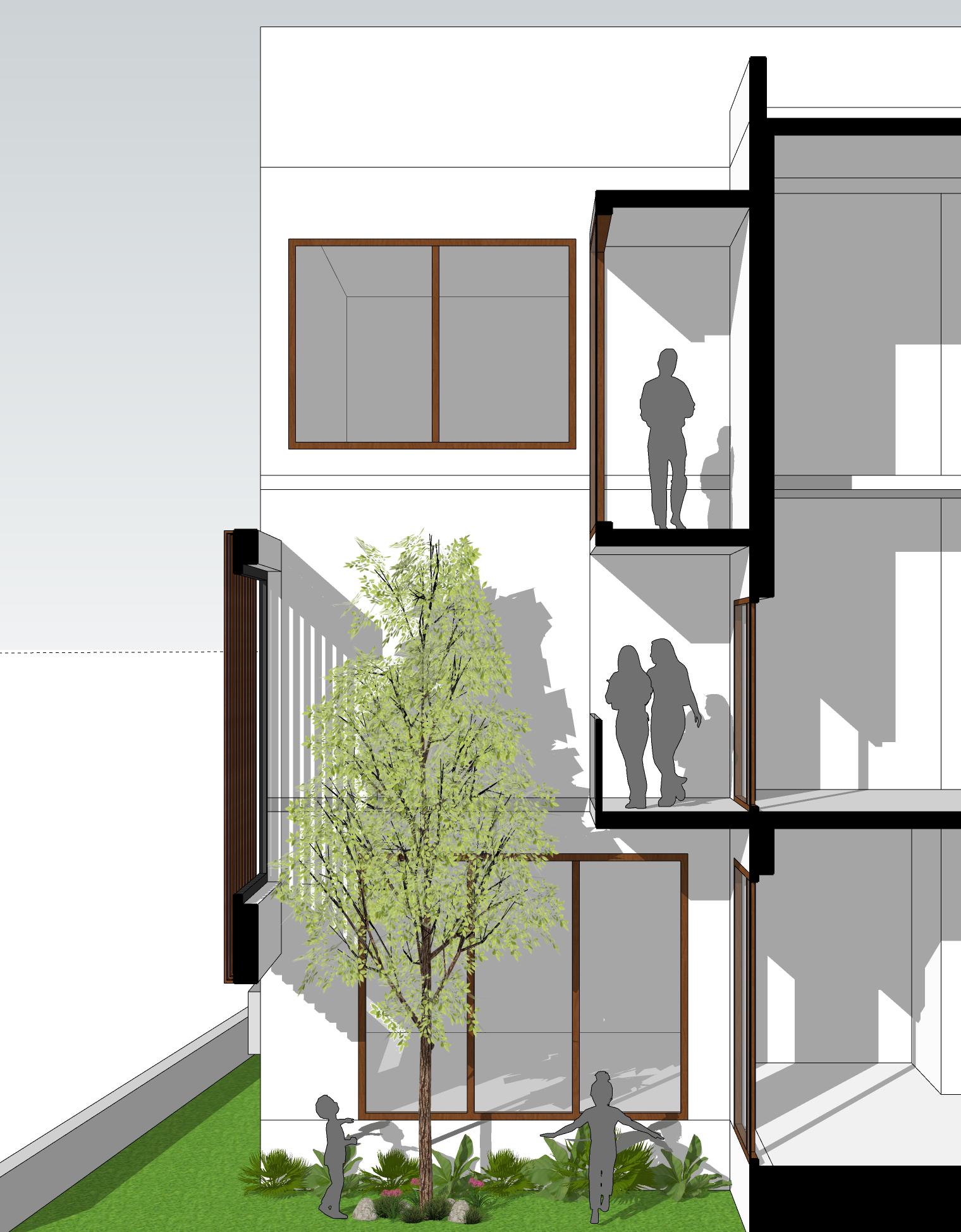
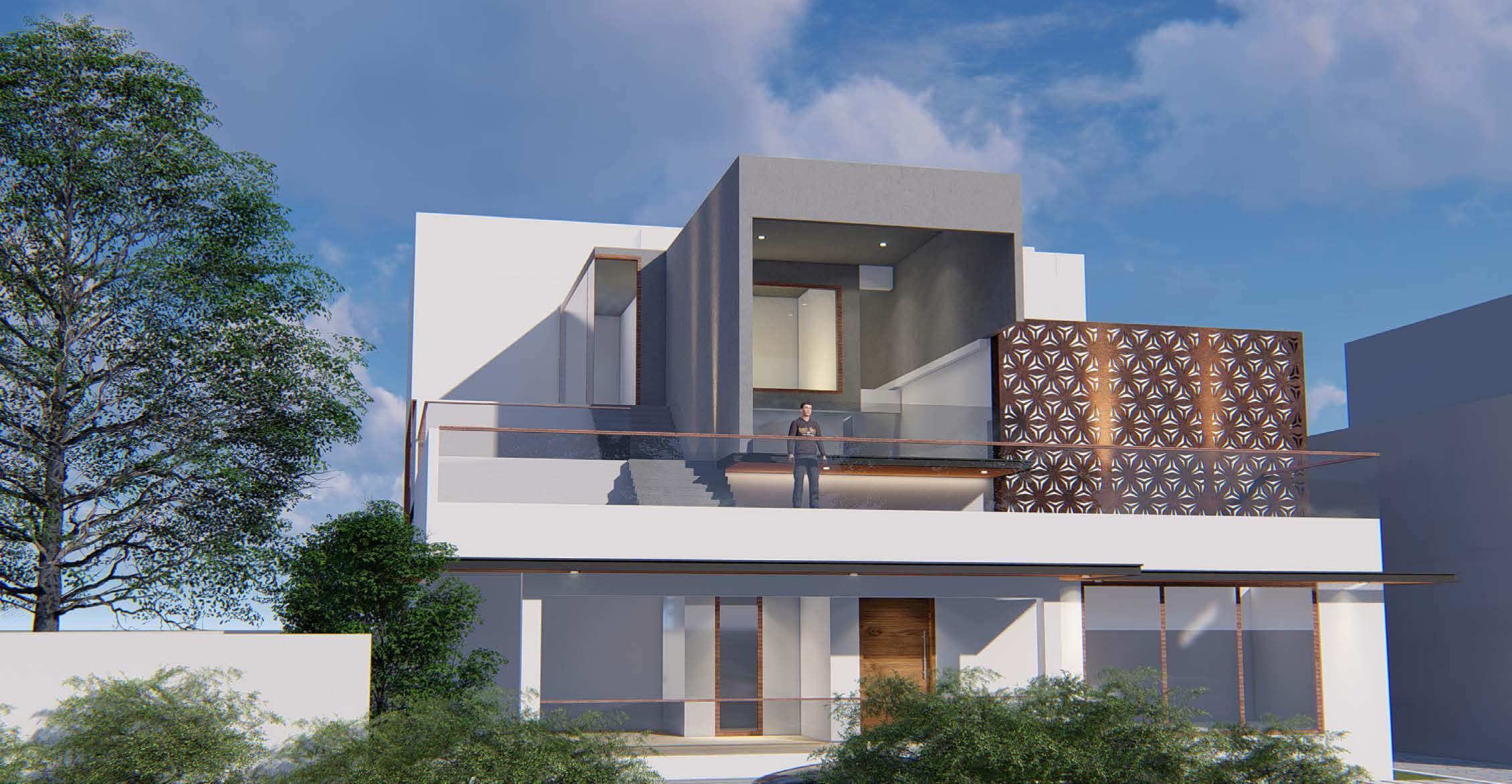
House of Tesseracts
Design Element:
The screen that gives the privacy to the private space of the house and prevents the indoor space from harsh sun and the pattern of the screen provides the dynamic shadow play into the space.
The Tree is the focal point from the balcony where it gives the balcony a private blend into the green space of the house.
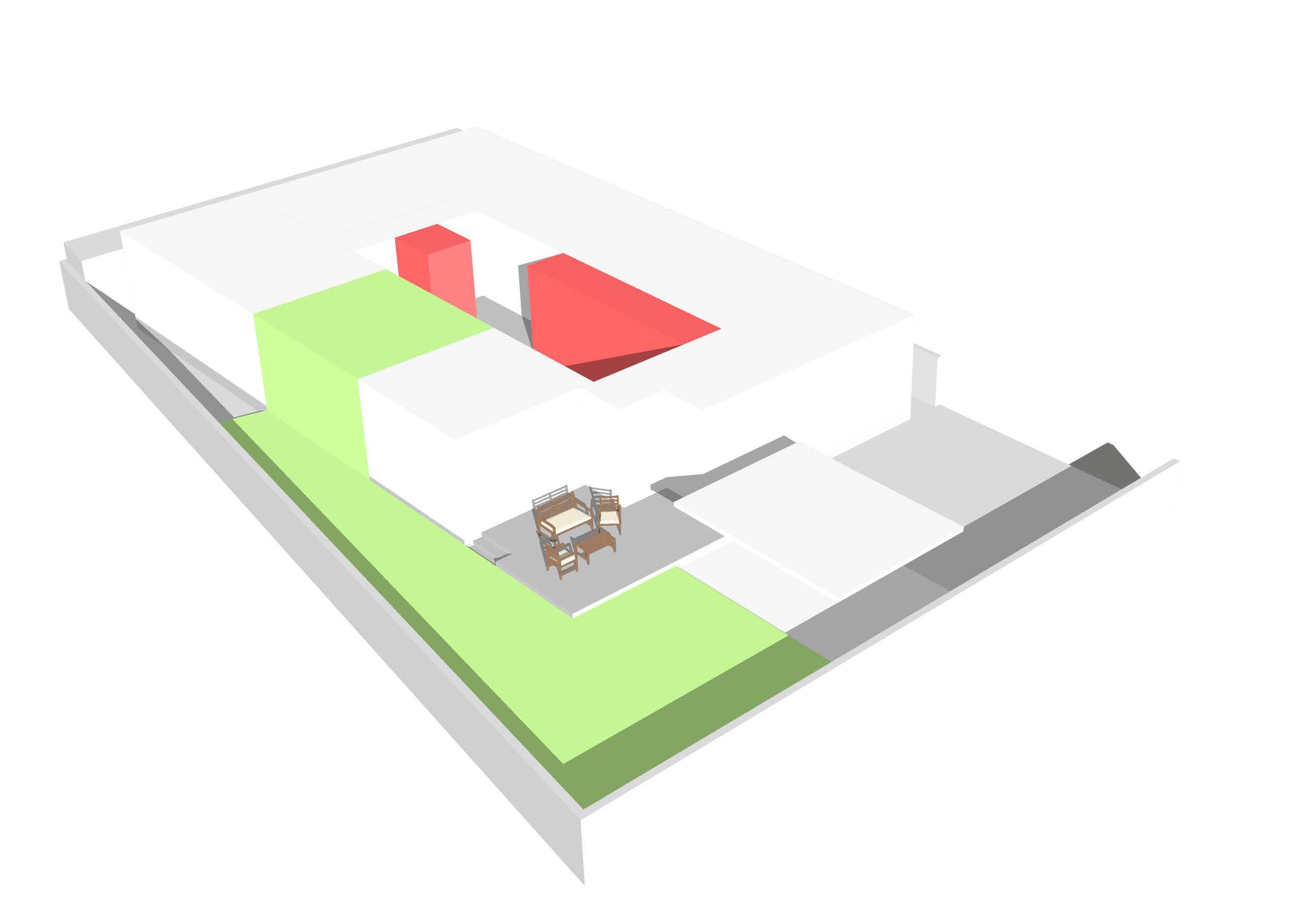
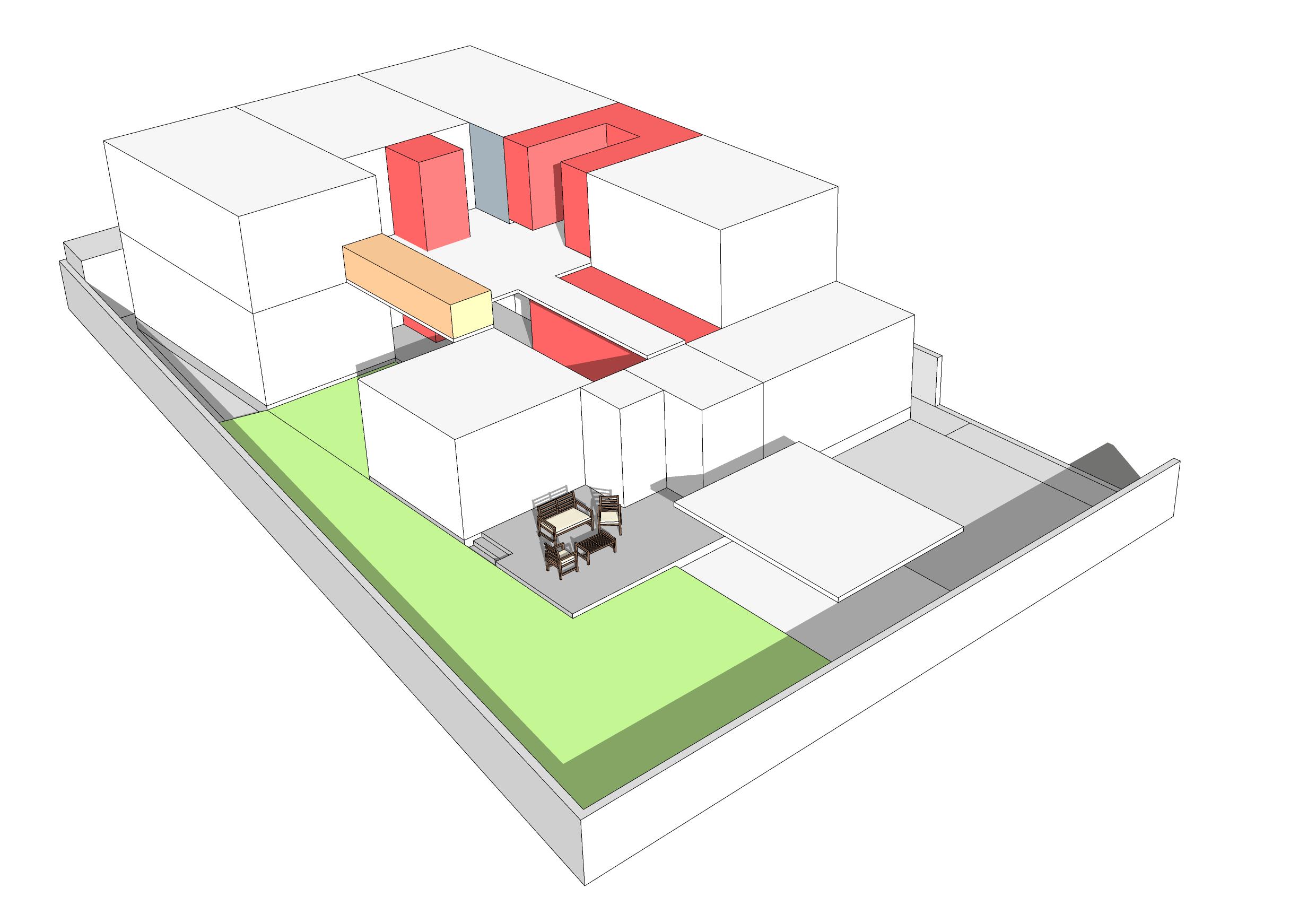
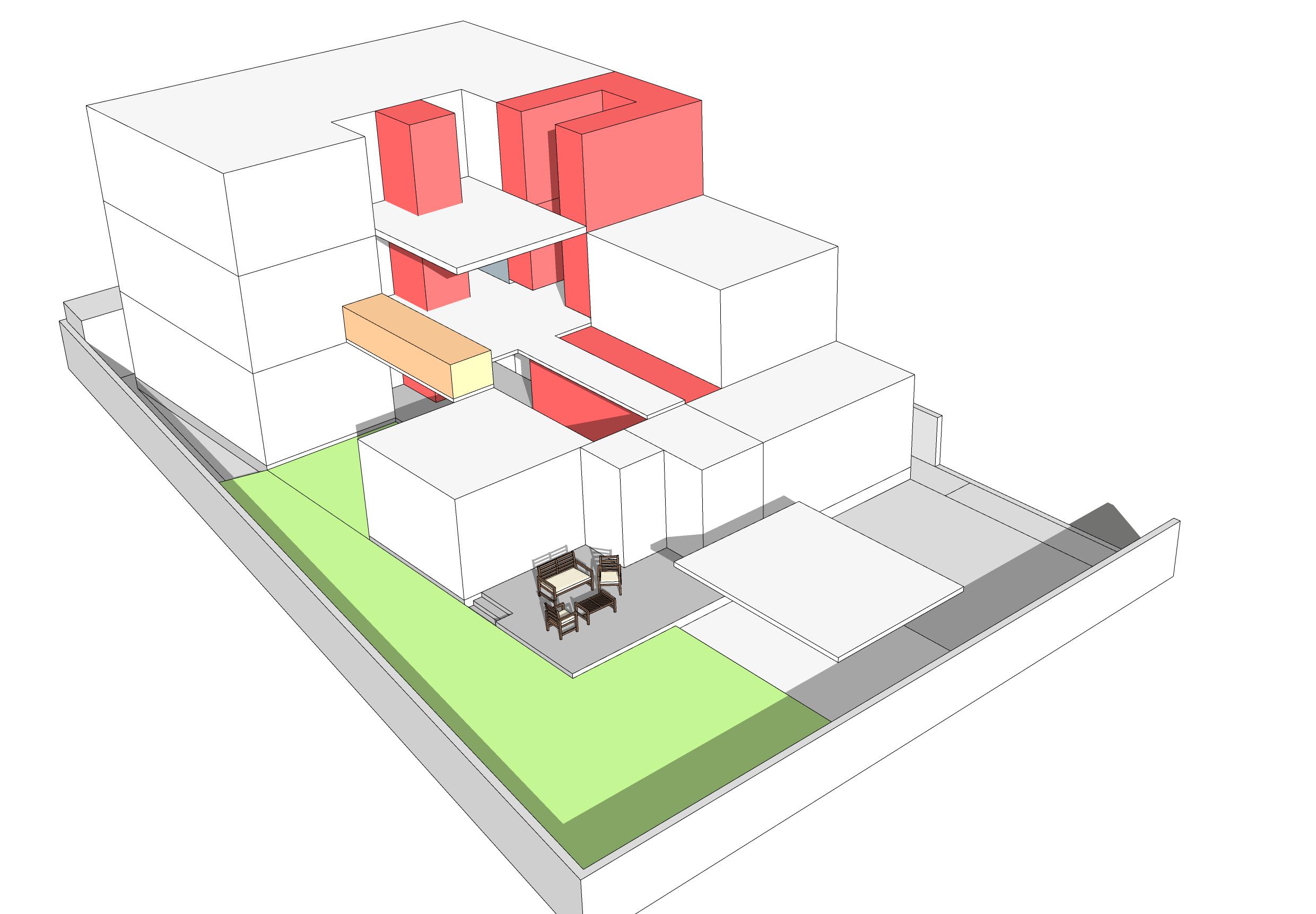
This is the model generated for the initial conceptual design of the plan and as per the client vision of the house has to be ageless and modern we decided to move forwarded to go with the shades of concrete and white.
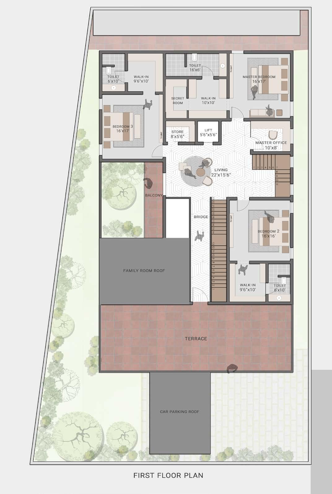
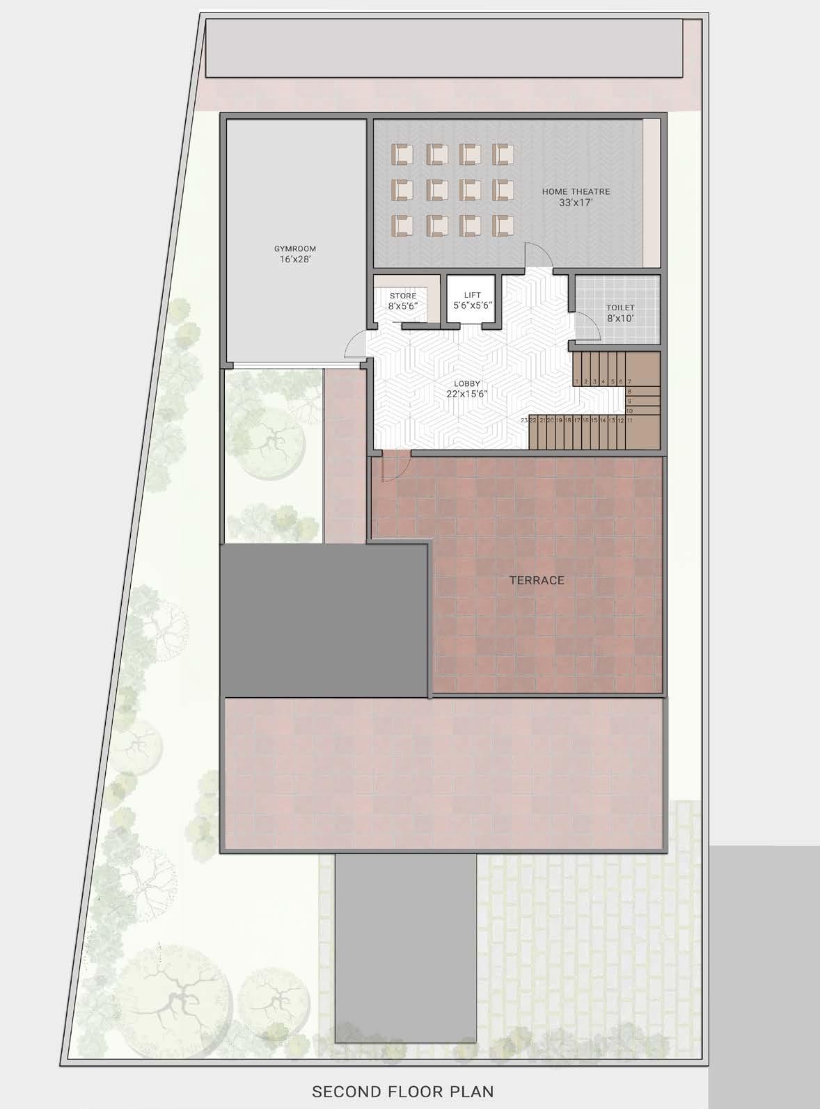
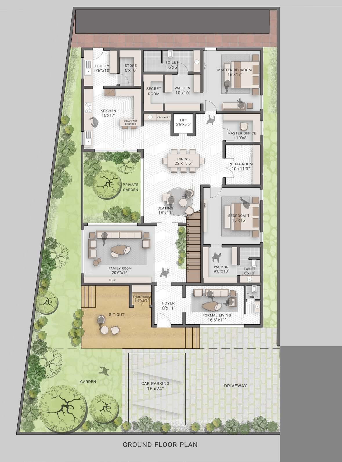
House of Tesseract:
This Bugalow is designed in the Sub-continent region India, Tamilnadu, The place where they are more blended towards their cultural aspects like vastu is like a set of rules where as the placement of the spaces like bedroom to be located at the south-west corner of the building, Pooja should be placed at the center of the house.
Client has vision of minimalistic approach towards the house so that the house that looks ageless and modern. Incorporating of the modern approach with the rules were the critical part in designing the house in such linear Site by bringing in natural light and ventilation.
The creation of Garden was a great idea because it is dividing the house from semi-public access to the private access and it will bring in enough amont of natural light to the circulating space of the house.
House of Tesseract Architectural Assistant Bungalow
Model: Sketchup Postproduction: Adobe PS & ID
drawings: Autocad
Private screen
Landscape Element
Balcony into green space
Schematic section
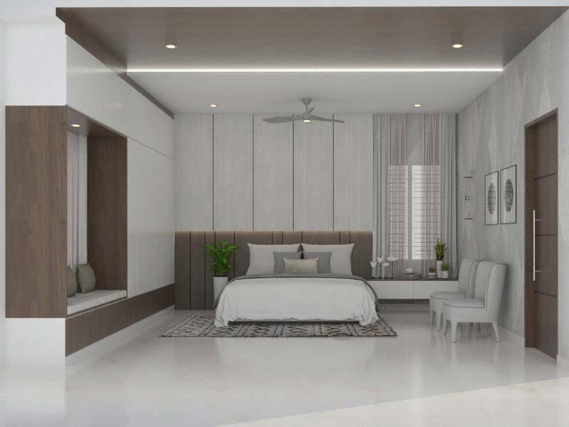
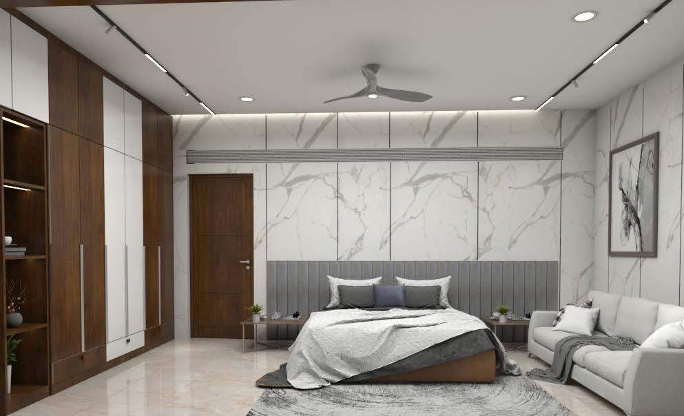
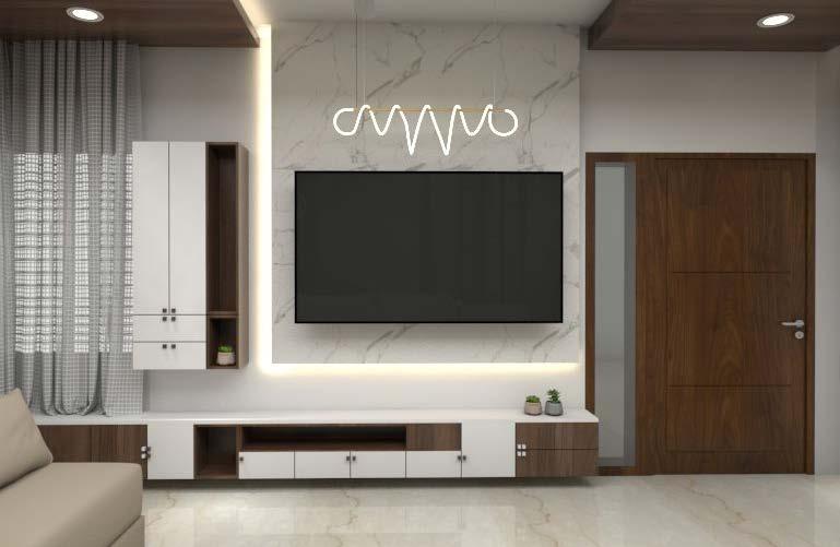
Interior of Tesseracts
House of Tesseract:
Since the house has been created in the concept of minimalism, we have designed the interior space with the same colour theme of white and wood.
These are the sample interior concepts of the house where we propose while presenting the initial stage of the design and we designed in such a way that the house should be seamless from exterior to interior.
The complete thought process of designing the interior the house has to look slim and slender so the lightings of this house were also designed accordingly to the clients idea of minimalism.
Master Bedroom
First floor Son’s Bed room
Living Room
Concept Development:
The site that we got was located by a dense neighbourhood and the client wanted an iconic landmark in that area.
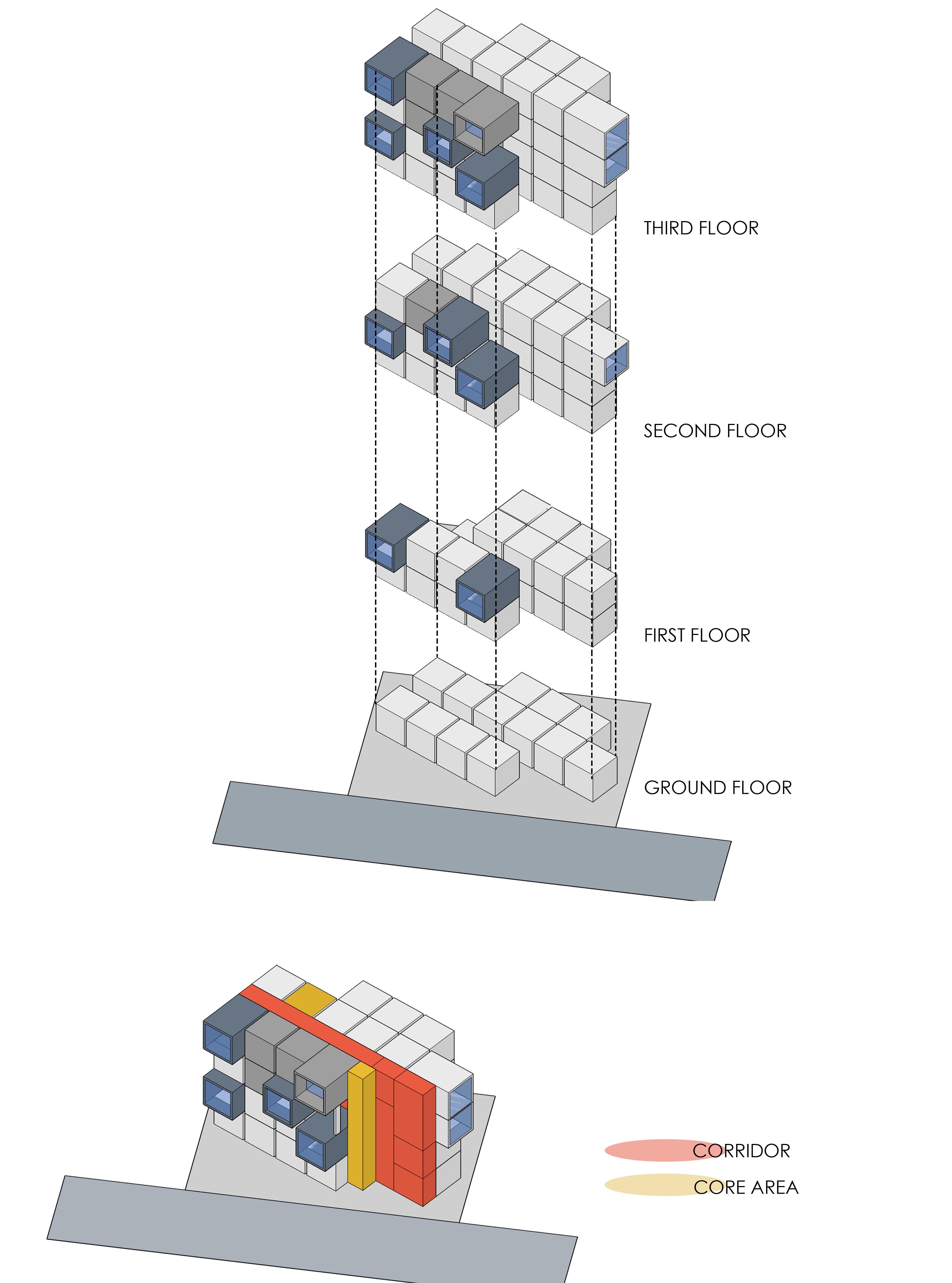
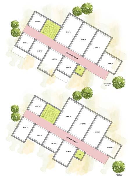
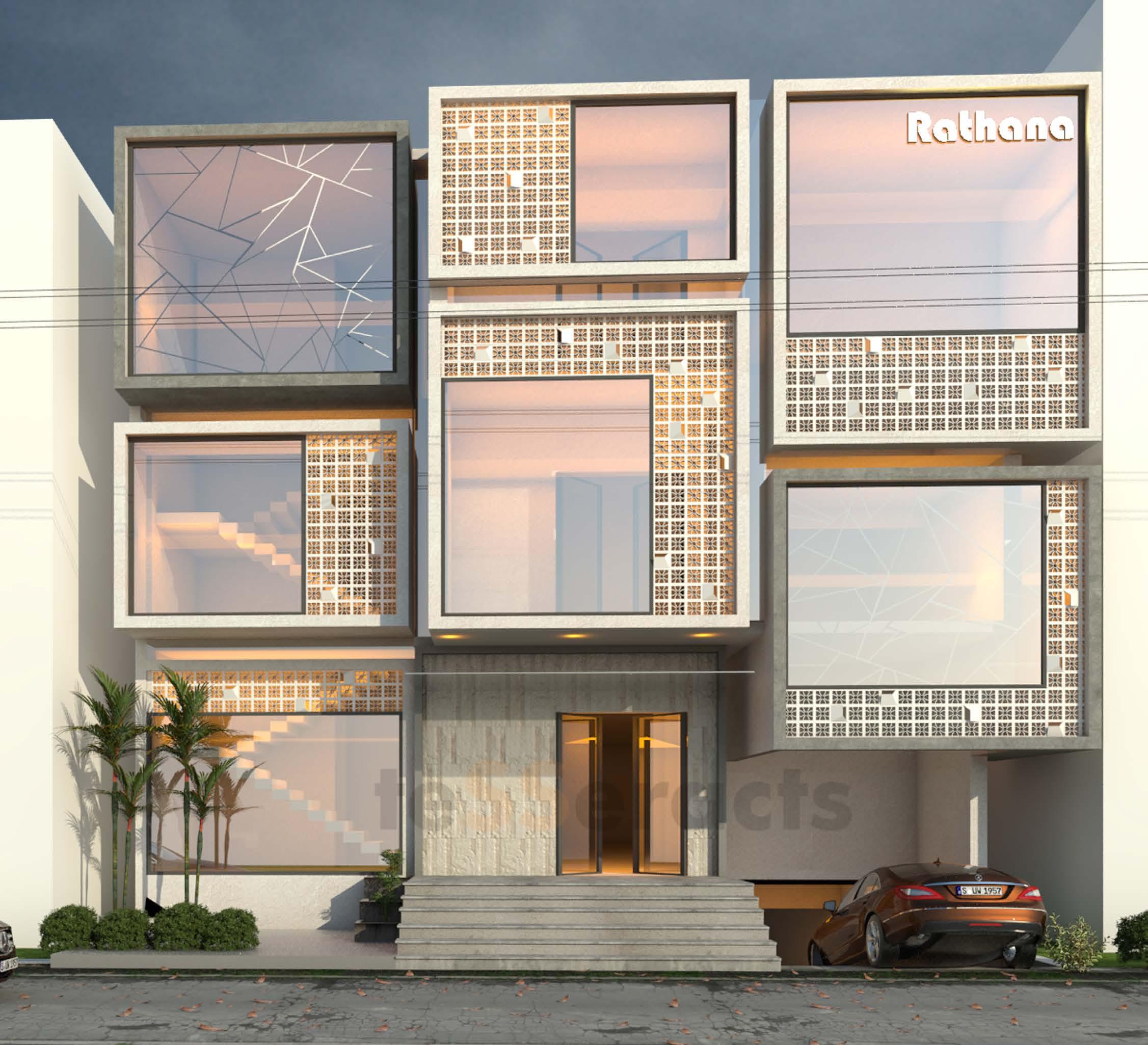
So The initial concept that strikes while designing the commercial complex is voxels. Because the voxcel that create a more usable and functionable space with less amount of facade ornamentation the juxta positioning the space itself bring form to the building.
Process of Voxelizing
Design Element:
The building is faced towards the north and the chances of getting harsh sunlight is less so we added insulated glass on the facade to make the volume of the shops looks bigger in scale and addition of jaali to bifurate the glass and a additional element to the facade and to make the building as a landmark in that specific location.
Airport walkway
LONGITUDINAL SECTION - A (PART-A)
12353
R3ERAFTER
= 10207 MM R4RAFTER RADIUS = 9672 MM R3CRAFTER RADIUS = 10833 MM R2CRAFTER RADIUS = 13108 MM R1RAFTER RADIUS = 14228 MM R2FRAFTER RADIUS = 12145 MM R3FRAFTER RADIUS = 10114 MM R4RAFTER RADIUS = 9672 MM R3ARAFTER RADIUS = 11313 MM R2ARAFTER RADIUS = 13400 MM R1RAFTER RADIUS = 14228 MM R2ERAFTER RADIUS = 12353 MM R3FRAFTER RADIUS = 10114 MM R4RAFTER RADIUS = 9672 MM R3CRAFTER RADIUS = 10833 MM R2BRAFTER RADIUS = 13273 MM R1RAFTER RADIUS = 14228 MM R2BRAFTER RADIUS = 13273 MM R3ARAFTER RADIUS = 11313 MM R4RAFTER RADIUS = 9672 MM R4BRAFTER RADIUS = 9240 MM R4RAFTER
SECTION - A (PART-B)
Detail Plan at Walkway level:
This detailed plan view is focused on the walkway level, showing the layout and positioning of the fins relative to the walkway. It includes measurements and spatial relationships between different structural elements.
Plan View:
At the bottom of the sheet, there is a plan view showing the top-down layout of the fins along the walkway. It’s divided into sections labeled A to N, with specific fin groups (Group 1, Group 2, etc.) assigned to each section. This plan likely provides the necessary information for aligning and installing the fins correctly in the designated areas.
LONGITUDINAL
Fabrication data of the Fins:
These are generalized elevation views that give an overall idea of how the fins look when installed on the building. It provides a holistic view of the design and arrangement of the fins.
Detail A:
This section shows a detailed cross-section of a particular area (presumably where the fins are installed). The cross-section includes measurements and specifications, such as the height of the fins, their attachment points, and other structural details.
Fins and Elevation:
On the left side of the sheet, there are detailed elevation drawings for different groups of fins, labeled from Group 1 to Group 6. These elevations show the shape and configuration of the fins for each group, likely indicating the specific design patterns or profiles that will be used in the construction.
Material Used on the roof:
Kalzip sheets, ideal for complex architectural designs, offer flexibility to fit curved forms like those at Bangalore Airport’s Terminal 2. They provide excellent thermal and acoustic insulation, enhancing energy efficiency and comfort by reducing heat transfer and noise levels.
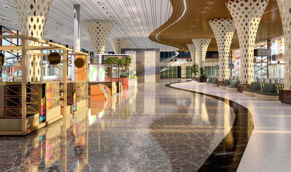
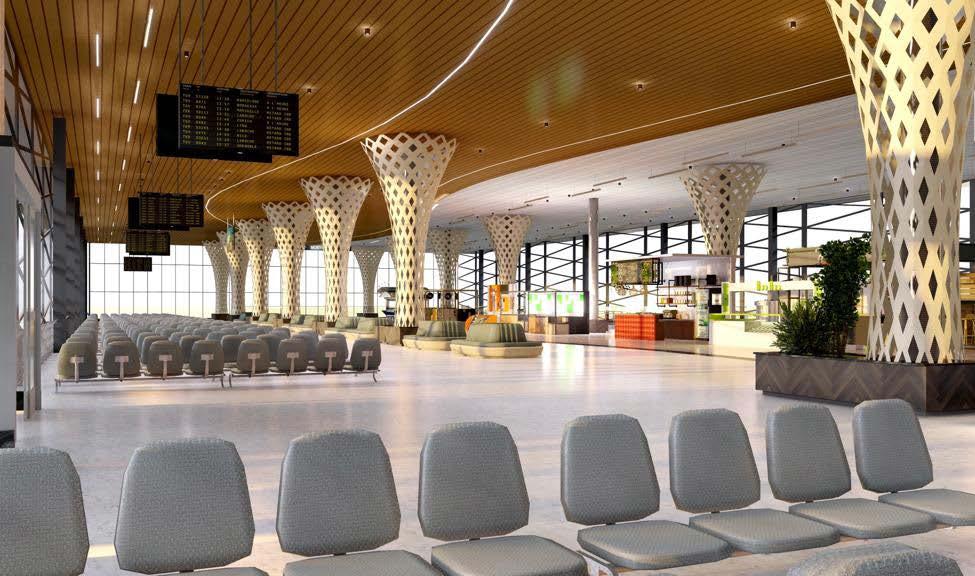
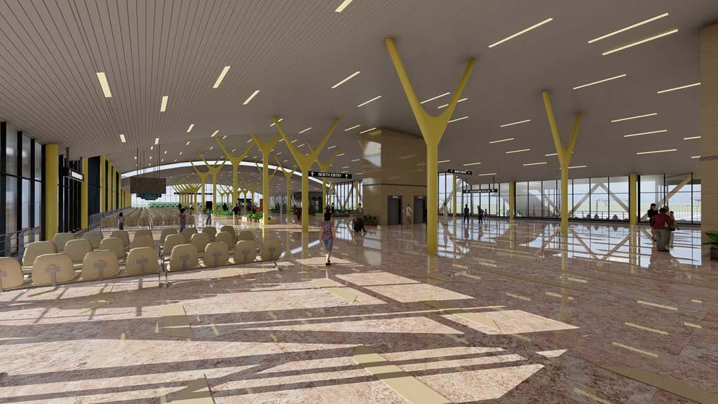
Railway station Air Concourse
Interior Air Concourse proposal: Government officials of the railway authority plan to design the Kollam railway air concourse to resemble an airport, with a concept inspired by the flow of fluids. The materiality includes Hunter Douglas ceiling panels for durability and aesthetics, GFRC panels for column cladding offering strength and versatility, and high-durability 20 mm full-body tiles for robust, wear-resistant flooring. The design integrates modern elements to ensure a sleek, efficient, and comfortable environment for passengers. These are all the two options given as a proposal.
Fabrication Techniques
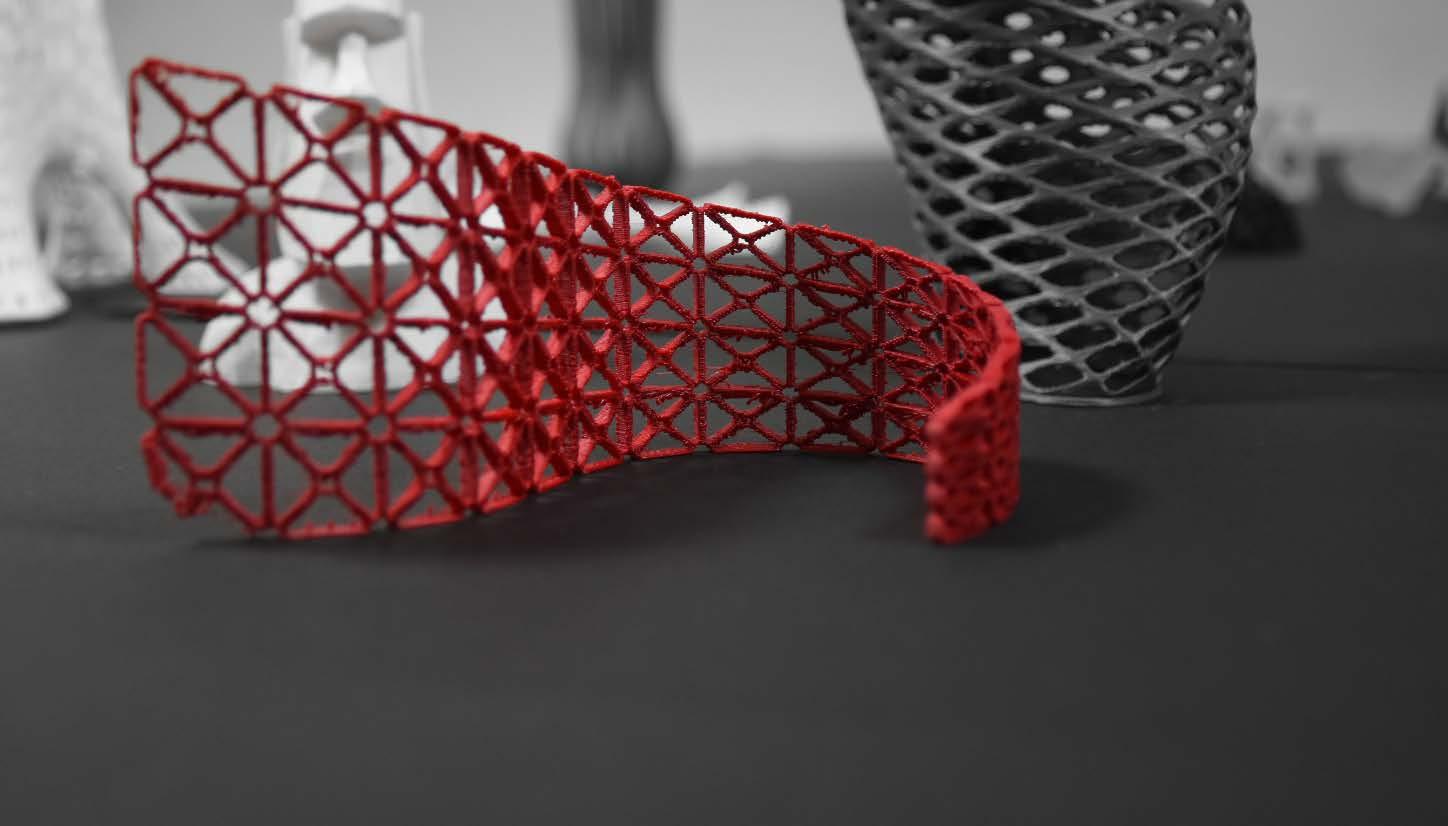
Computational Fabrication projects
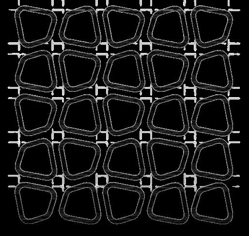
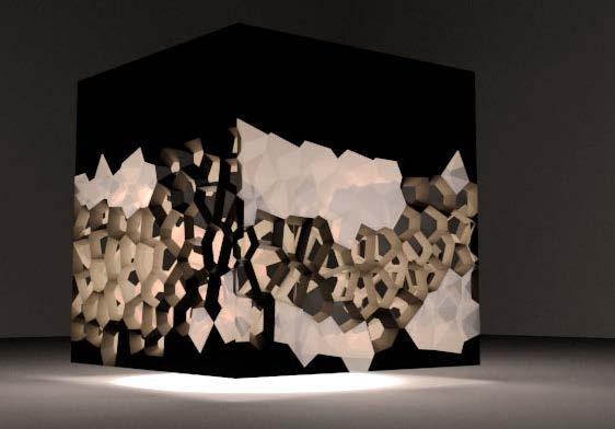
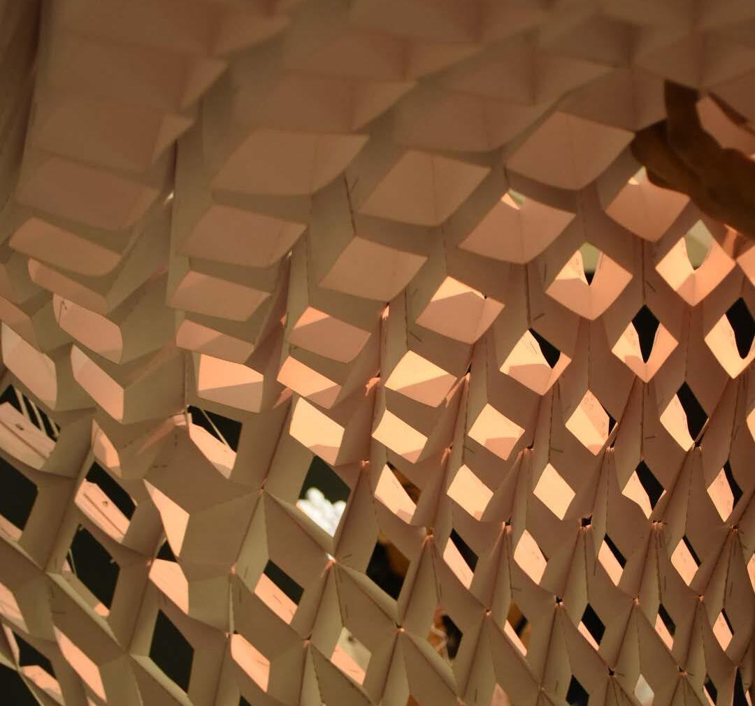
These images showcase some of the best computational fabrication projects I’ve completed both individually and as part of a group. The top-left image is a 3d printed red lattice structure with complex geometric patterns. The top-right image reveals a close-up of an intricate, interlocking design resembling mesh structure constructed and executed with diagonal square pattern with variable sizes of opening. The bottom image features a cube with an organic, perforated surface illuminated from within, highlighting the detailed texture and craftsmanship. Each project demonstrates advanced design and fabrication techniques, emphasizing precision and creativity.