Programmable Logic Controllers 5th Edition Petruzella Solutions Manual
To download the complete and accurate content document, go to: https://testbankbell.com/download/programmable-logic-controllers-5th-edition-petruze lla-solutions-manual/

Programmable Logic Controllers 5th Edition Petruzella Solutions Manual Visit TestBankBell.com to get complete for all chapters
CHAPTER 7 Programming Timers
TEST 7 . 1
Choose the letter that best completes the statement. Answer
1. Certain contacts of a mechanical timing relay are 1. d designed to operate at a preset time interval:
a) after the coil is energized.
b) after the coil is de-energized.
c) after power is applied to the circuit.
d) either a or b.
2. Which of the symbols shown in Figure 7-1 represents 2. a an on-delay timed relay contact?

3. The relay contact drawn in Figure 7-2 is designed 3. d to operate so that:
a) when the relay coil is energized, there is a time delay in closing.
b) when the relay coil is energized, there is a time delay in opening.
c) when the relay coil is de-energized, there is a time delay before the contact opens.
d) when the relay coil is de-energized, there is a time delay before the contact closes.
rights reserved. No reproduction or distribution
prior written
1
Copyright (c) 2017 McGraw-Hill Education. All
without the
consent of McGraw-Hill Education.
Figure 7-1 Symbols for question 2.
4. In the hardwired circuit of Figure 7-3, the light 4. b will stay on:

a) as long as S1 is closed.
b) for 5 s after coil TD is energized.
c) for 5 s after coil TD is de-energized.
d) both a and c.
5. Which one of the following timer parameters 5. b determines the time duration for the timing circuit?
a) Accumulated time.
b) Preset time.
c) Timer address.
d) Time base.
6. Which one of the following timer parameters 6. a represents the value that increments as the timer is timing.?
a) Accumulated time.

No reproduction or distribution
2
Copyright (c) 2017 McGraw-Hill Education. All rights reserved.
without the prior written consent of McGraw-Hill Education.
Figure 7-2 Contact symbol for question 3.
Figure 7-3 Hardwired circuit for question 4.
b) Preset time.
c) Timer address.
d) Time base
7. Which one of the following timer parameters 7. d determines the accuracy of the timer?
a) Accumulated time.
b) Preset time.
c) Timer address.
d) Time base.
8-1 The timer shown in Figure 7-4 would be classified as a: 8-1. a
a) on-delay timer
b) off-delay timer
c) normally open timer
d) normally closed timer
8-2. The timing commences when 8-2. a
a) the input instruction is True.
b) the input instruction is False.
c) power is applied.
d) power is removed
Copyright (c) 2017 McGraw-Hill Education. All rights reserved.
without the prior written consent of McGraw-Hill Education.
reproduction
3
No
or distribution
9. The timer file for SLC 500 controllers is: 9. d
a) T1
b) T2
c) T3
d) T4
10-1. For the on-delay timer instruction shown in 10-1. c
Figure 7-5, the timer number is:

a) 0
b) 200
c) T4:3
d) 0.1 10-2. The on-delay timed period would be: 10-2. c
a) 3 seconds
b) 4 seconds
c) 20 seconds
d) 200 seconds
No reproduction or distribution
4
Copyright (c) 2017 McGraw-Hill Education. All rights reserved.
without the prior written consent of McGraw-Hill Education.
Figure 7-4 Timer program for question 8.
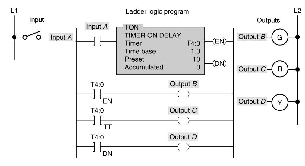
11-1. For the on-delay timer program shown in 11-1. b

Figure 7-6, output B is switched ON when:
a) power is applied.
b) input A is closed.
c) the timer is accumulating time.
d) the accumulated value equals the preset value. 11-2. Output C is switched ON when: 11-2. c
a) power is applied.
b) input A is closed.
c) the timer is accumulating time.
d) the accumulated value equals the preset value. 11-3. Output D is switched ON when: 11-3. d
a) power is applied.
b) input A is closed.
c) the timer is accumulating time.
d) the accumulated value equals the preset value. 11-4. The timer accumulated value will reset to 11-4. a zero whenever:
a) input A switch is opened.
5
Copyright (c) 2017 McGraw-Hill Education. All rights reserved. No reproduction or distribution without the prior written consent of McGraw-Hill Education.
Figure 7-5 Timer instruction for question 10.
b) input A switch is closed.
c) the DN bit is set to 1.
d) the EN bit is set to 1.
12. For the timer table shown in Figure 7-7, bit level 12. b addressing is used for:

a) EN, TT, PRE and ACC
b) EN, TT, and DN
c) PRE, ACC, TT and EN
d) PRE and ACC
Copyright (c) 2017 McGraw-Hill Education. All rights reserved. No reproduction or distribution without the prior written consent of McGraw-Hill Education.
6
Figure 7-6 Timer program for question 11.
Figure 7-7 Timer table for question 12.
13. For the hardwired timer circuit of Figure 7-8, 13. c contact TD-1 is the ____ contact and TD-2 is the ____ contact.

a) ON, OFF
b) OFF, ON
c) instantaneous, timed
d) timed, instantaneous
14-1. For the programmed timer circuit of Figure 7-9, 14-1. b the ____ bit of the timer functions similar to an instantaneous contact.
a) DN
b) EN
c) PB1
d) PB2 14-1. The ____ bit of the timer functions similar to a 14-2. a timed contact.
a) DN
b) EN
c) PB1
d) PB2
Copyright (c) 2017 McGraw-Hill Education. All rights reserved.
7
No reproduction or distribution without the prior written consent of McGraw-Hill Education.
Figure 7-8 Hardwired timer for question 13.
15. The on-delay timer (TON) starts timing when the timer's: 15. a

a) ladder rung switches from false to true.
b) ladder rung switches from true to false.
c) accumulated value equals its preset value
d) accumulated is greater than its preset value
16. The off-delay timer (TOF) starts timing when the timer's: 16. b
a) ladder rung switches from false to true.
b) ladder rung switches from true to false.
c) accumulated value equals its preset value
d) accumulated is greater than its preset value
17. For the programmed timer circuit of Figure 7-10, 17. d
the pilot light should come on:
a) as soon as the switch is closed.
b) before the switch is closed.
Copyright (c)
McGraw-Hill Education. All rights reserved. No reproduction or distribution without the prior written consent of McGraw-Hill Education. 8
2017
Figure 7-9 Programmed timer for question 14.
c) for 15 seconds after the switch is opened.
d) both a and c.
18-1. For the programmed timer circuit of Figure 7-11, 18-1. d when the switch is initially closed motor(s) _____ start(s) immediately.

a) M1
b) M2
c) M3
d) all of these
18-2. Assume the switch is closed for 5 seconds and than 18-2. c opened. After 12 seconds have elapsed motor(s) ____ will still be operating.
a) M1, M2, M3
b) M2, M3
c) M3
d) none of these
(c)
McGraw-Hill Education.
rights reserved. No reproduction or distribution
the prior written
9
Copyright
2017
All
without
consent of McGraw-Hill Education.
Figure 7-10 Programmed timer for question 17.
19. The main difference between a TON and TOF timer is that the: 19. c
a) TON timer can maintain its accumulated time on loss of power or logic continuity.
b) TOF timer can maintain its accumulated time on loss of power or logic continuity.
c) TOF timer begins timing when logic continuity to the timing rung is lost.

d) TON timer begins timing when logic continuity to the timing rung is lost.
20. The operation of a PLC retentive timer is similar to that of an: 20. b
a) electromagnetic pneumatic timer.
No reproduction or distribution
the prior
10
Copyright (c) 2017 McGraw-Hill Education. All rights reserved.
without
written consent of McGraw-Hill Education.
Figure 7-11 Programmed timer for question 18.
b) electromechanical motor-driven timer.
c) off-delay timer.
d) on-delay timer.
21. The main difference between a PLC retentive and 21. c nonretentive timer is that the:
a) retentive timer can be programmed for much longer time delay periods.
b) nonretentive time can be programmed for much longer time delay periods.
c) retentive timer maintains the current time should power be removed from the device or when the timer rung goes false.
d) nonretentive timer maintains the current time should power be removed from the device or when the timer rung goes false.
22. Unlike the TON timer, the RTO timer requires a(n): 22. a
a) timer reset instruction.
b) input condition instruction.
c) internal relay instruction.
d) instantaneous contact instruction.
23. When addressing an RES instruction, it must be addressed to: 23. d
a) a TOF instruction.
b) a TON instruction.
c) any address other than the of the RTO instruction.
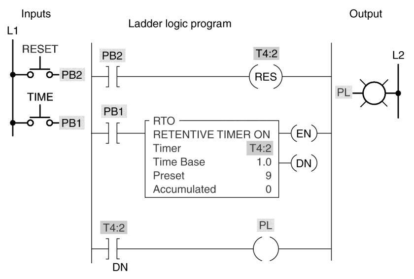
d) the same address as that of the RTO instruction. 24-1. The type of timer programmed in Figure 7-12 is a: 24-1 a
Copyright (c) 2017 McGraw-Hill Education. All rights reserved. No reproduction or distribution without the prior written consent of McGraw-Hill Education. 11
a) retentive on-delay.
b) retentive off-delay.
c) nonretentive off-delay
d) nonretentive on-delay.
24-2. The timer starts timing when: 24-2. a
a) PB1 is closed.
b) PB2 is closed.
c) both PB1 and PB2 are closed.
d) either PB1 or PB2 is closed.
24-3. The timer accumulated time is set to zero anytime: 23-4. b
a) PB1 is closed.
b) PB2 is closed.
c) PB1 is open.
d) PB2 is open.
Copyright (c) 2017 McGraw-Hill Education. All rights reserved. No reproduction or distribution without the prior written consent of McGraw-Hill Education.
12
Figure 7-12 Programmed timer for questions 24, 25, and 26.
25. For the timer program of Figure 7-12, assume the following sequence of events:
➢ First PB2 is momentarily pressed closed.
➢ Next PB1 is pressed closed for 5 s and released.
➢ Next PB2 is pressed closed for 4 s and released.
25-1. As a result, the timer-accumulated value at the 25-1. d end of the sequence would be:
a) 5
b) 4
c) 9
d) 0
25-2. As a result, the output PL would be: 25-2. d
a) on for 4 s and off for 5 s.
b) on for 5 s and off for 4 s.
c) on after the entire sequence has been completed.
d) off after the entire sequence has been completed.
26. For the timer program of Figure 7-12, assume the following sequence of events:
➢ First PB2 is momentarily pressed closed.
➢ Next PB1 is pressed closed for 3 s and released.
➢ Next PB1 is again pressed closed for 6 s and released.
26-1. As a result, the timer accumulated value at the end of 26-1. c the sequence would be:
(c)
Education.
rights reserved. No reproduction or distribution
the prior written
13
Copyright
2017 McGraw-Hill
All
without
consent of McGraw-Hill Education.
a) 3
b) 6
c) 9
d) 0
26-2. As a result, output PL would be: 26-2. c
a) on for 3 s and off for 6 s.
b) off for 3 s and on for 6 s.
c) on after the entire sequence has been completed.
d) off after the entire sequence has been completed.
27. To reset a retentive timer, the: 27. d
a) AC time must be greater than the PR time.
b) PR time must be greater than the AC time.
c) AC time must equal the PR time.
d) none of these.
28. The interconnecting of timers is commonly called: 28. d
a) grouping.
b) programming.
c) sequencing.
d) cascading.
rights reserved. No reproduction or distribution
the prior written
14
Copyright (c) 2017 McGraw-Hill Education. All
without
consent of McGraw-Hill Education.
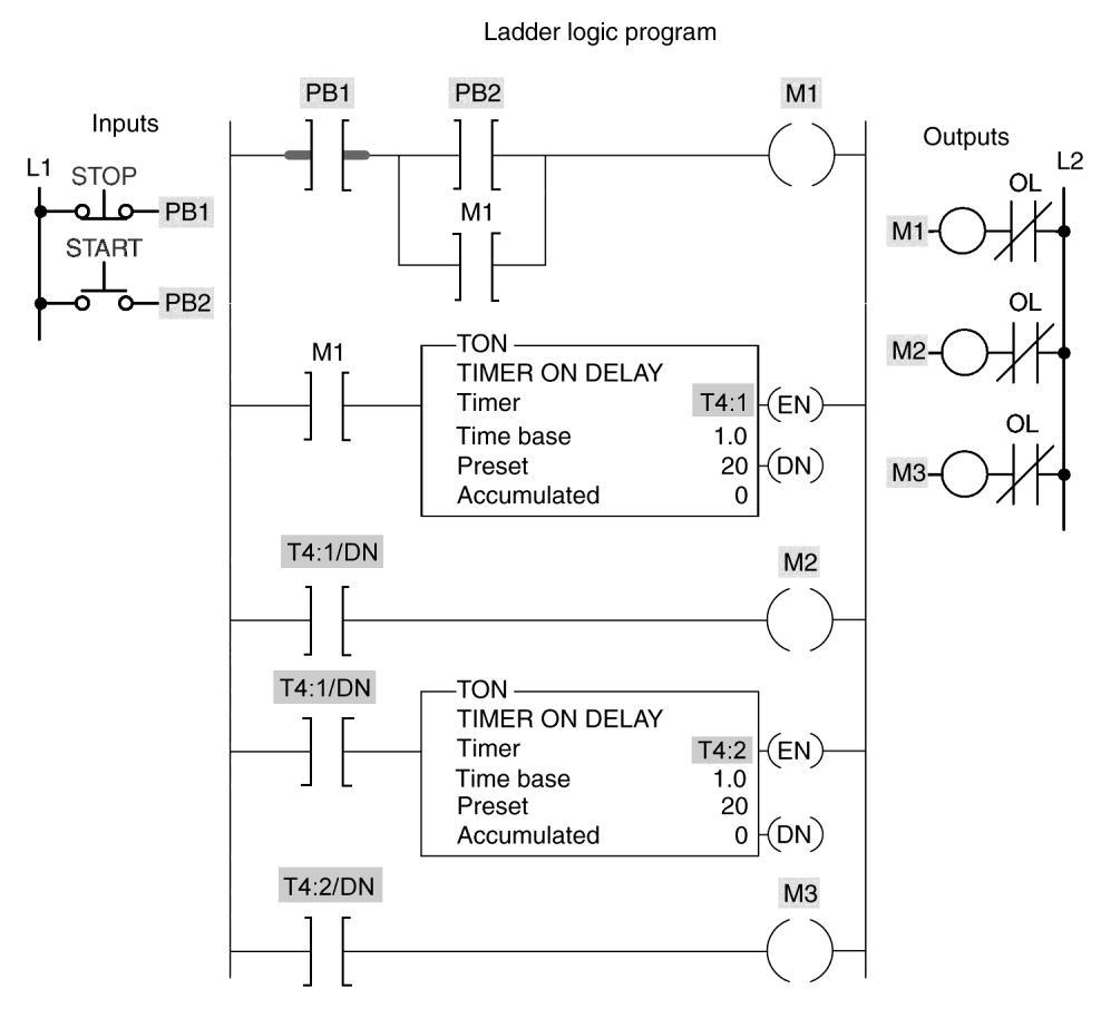
29-1. In the timer program of Figure 7-13, the timer 29-1. b
T4:1 is energized by actuating:
a) PB1.
b) PB2.
c) both PB1 and PB2.
d) either PB1 or PB2.
29-2. Output M1 is normally energized: 29-2. b
a) as soon as PB1 is actuated.
b) as soon as PB2 is actuated.
c) 10 s after PB1 has been actuated.
d) 40 s after both PB1 and PB2 have been actuated.
29-3. Output M2 is normally energized ____ after 29-3. b
output M1 has been energized.
a) 10 s
b) 20 s
c) 30 s
d) 40 s
29-4. Output M3 is normally energized ____ after 29-4. d
output M1 has been energized.
a) 10 s
b) 20 s
c) 30 s
d) 40 s
15
Copyright (c) 2017 McGraw-Hill Education. All rights reserved. No reproduction or distribution without the prior written consent of McGraw-Hill Education.
30-1. In the annunciator flasher program of Figure 7-14, 30-1. c the two timers are interconnected to form a(n):
a) amplifier circuit.
b) rectifier circuit.
c) oscillator circuit.
d) series/parallel circuit.
30-2. The output of timer T4:5 : 30-2. d
a) turns on after a 10-s time delay and remains on.
b) turns off after a 2-s time delay and remains off.
c) turns on after a 3-s time delay and remains on.
No reproduction or distribution
prior
16
Copyright (c) 2017 McGraw-Hill Education. All rights reserved.
without the
written consent of McGraw-Hill Education.
Figure 7-13 Programmed timer for question 29.
d) is pulsed on and off at 1-s intervals.
30-3. When pressure switch PS1 closes, the: 30-3. d

a) green indicating lamp is turned on.
b) red indicating lamp is turned on.
c) yellow indicating lamp is pulsed on and off.
d) red indicating lamp is pulsed on and off.
31. Which instruction can best be used to turn an output 31. d coil on or off after the rung has been false for a desired time?
a) RTO
b) TON
No reproduction or
17
Copyright (c) 2017 McGraw-Hill Education. All rights reserved.
distribution without the prior written consent of McGraw-Hill Education.
Figure 7-14 Programmed flasher timer for question 30.
c) ONOF
d) TOF
32. The amount of time for which a timer
32. a is programmed is called the:
a) Preset
b) Desired Time
c) Set Point
d Lapsed Time
33. When the timing of a device is not reset on a 33. c loss of power, the timing is said to be:
a) continuous
b) holding
c) retentive
d) saved
34. RES instructions are used with: 34. c
a) TOF timers
b) TON timers
c) RTO timers
d) all of these
Education. All rights reserved. No reproduction or distribution
the prior written
18
Copyright (c) 2017 McGraw-Hill
without
consent of McGraw-Hill Education.
CHAPTER 7
Programming Timers
TEST 7 . 2
Place the answers to the following questions in the answer column at the right. Answer
1. Mechanical timing relays are used to ___the opening
1. delay or closing of contacts for circuit control.
2. An off-delay timing relay provides time delay when
2. de-energized its coil is ____ .
3. For the timer relay contact shown in Figure 7-15,

3. True when the relay coil is energized, there is a time delay before the contact closes. (True/False)
4. For the timer relay contact shown in Figure 7-16, when
4. True the relay coil is de-energized, there is a time delay before the contact opens. (True/False)
Figure
Timed contact for question 4.

rights reserved. No reproduction or distribution
prior
19
Copyright (c) 2017 McGraw-Hill Education. All
without the
written consent of McGraw-Hill Education.
Figure 7-15 Timed contact for question 3.
7-16
5. For the timer relay contact shown in Figure 7-17, 5. True when the relay coil is de-energized, there is a time delay before the contact closes. (True/False)
Figure 7-17 Timed contact for question 5.
6. For the timer relay contact shown in Figure 7-18, 6. True when the relay coil is energized, there is a time delay before the contact opens. (True/False)
7. PLC timers are input instructions that provide the 7. False same functions as mechanical timing relays. (True or False)


8. Timer instructions are found on all PLCs manufactured 8. True today. (True or False)
9. Timer instructions may be (a) ____formatted
9a. coil or (b) ____formatted. 9b. block
10. The parts of a timer instruction include:
No reproduction or distribution
20
Copyright (c) 2017 McGraw-Hill Education. All rights reserved.
without the prior written consent of McGraw-Hill Education.
Figure 7-18 Timed contact for question 6.
a) ____, b) ____, c) ____, d) ____, and e) ____. 10b.
10c.
10a. Type
Address
Time base
10d. Preset
10e. Accumulated
11. The timer output is energized when the 11a. preset a) ____ time equals the b) ____ time. 11b. accumulated
12. If the preset time of a timer is 100 and the 12. 10 time base is 0.1, the time-delay period would be ____s.
13. A (n) ____ timer must be intentionally reset with 13. retentive a separate signal.
14. The retentive timer reset (RES) instruction is always 14. True given the same address as the timer it resets. (True or False)
15. An alarm is to be switched on whenever a piping 15. False system has sustained a cumulative overpressure of 60 s. The most directly applicable timer to use would be the on-delay nonretentive timer.
(True or False)
16. A lamp is to be switched off 10 s after a switch has 16. True been switched from its on to off position. The most directly applicable timer to use would be the off-delay nonretentive timer.
(True or False)
17. When a time-delay period longer than the maximum 17. True preset time allowed for a single timer is required, the problem can be solved by programming two or more timers together. (True or False)
No reproduction or distribution
prior
21
Copyright (c) 2017 McGraw-Hill Education. All rights reserved.
without the
written consent of McGraw-Hill Education.
18. Normally, the reset input to a timer will override the 18. True control input of the timer. (True or False)
19. A retentive timer must be completely timed out 19. False to be reset. (True or False)
20. Retentive timers lose the accumulated time every 20. False time the rung condition becomes false. (True or False)
21. The instantaneous contacts of a timer have 21. True no time-delay period associated with them. (True or False)
22. What timer instruction (TON, TOF, or RTO) would be best suited for each of the following control application:
a) Keep track of the total time to make one 22a. RTO batch of product, even if the process is halted and then started again .
b) Hold the clamp on for 25 s after the glue is applied. 22b. TOF
c) Open a valve 27 s after a switch is turned on. 22c. TOM If interrupted, the valve should close and the time should reset to 0.
d) Begin timing when the rung is true and hold the 22d. RTO accumulated time when rung logic goes false.
22
Copyright (c) 2017 McGraw-Hill Education. All rights reserved. No reproduction or distribution without the prior written consent of McGraw-Hill Education.
23. The accumulated time of a TOF timer is reset 23. False by causing the rung to go true momentarily. (True or False)
24. A timer's ____ is the length of time the timer 24. preset is to time.
25. A timer's ____ specifies at what rate the 25. time base timer will increment.
26. A timer's ____ value is the current elapsed time. 26. accumulated
27. A RES (reset) instruction must be used to zero 27. True the accumulated value in an RTO timer. (True or False)
28. A timer's delay time equals the value in the 28. False ACC multiplied by the time base. (True or False)
29. Timers can be retentive or non-retentive.
29. True (True or False)
30. An RTO timer retains the present accumulated value 30. True when the rung goes false. (True or False)
31. A TOF timer starts to accumulate time when the 31. False rung becomes true. (True or False)
No reproduction or distribution
the prior
23
Copyright (c) 2017 McGraw-Hill Education. All rights reserved.
without
written consent of McGraw-Hill Education.
32. A TOF timer starts to accumulate time when the 32. True rung makes a true to false transition. (True or False)
33. One of the advantages of using a PLC for timing circuit 33. True applications is the entire timing function occurs inside the controller. True/False)
34. The only way to reset a TON instruction is to use a 34. False Reset (RES) instruction. (True/False)
35. When one timer's output triggers another timer's input, 35. cascaded those timers are referred to as .
36. The two quantities that most PLC timers display are 36a. preset (a) ____ time and (b) ____ time. 36b. accumulated
37. The timer Enable Bit (EN) is set whenever rung 37. True conditions are ____.
No
or
prior
24
Copyright (c) 2017 McGraw-Hill Education. All rights reserved.
reproduction
distribution without the
written consent of McGraw-Hill Education.
Programming Assignments
For Chapter 7
This section will present several common timing program applications. The instructions used are intended to be generic in nature and, as such, will require some conversion for the particular PLC model you are using. The use of a prewired PLC input/output control panel is recommended to simulate the operation of these circuits.
1. Prepare an I/O connection diagram and ladder logic program for a non-retentive on-delay timer that will turn a light on 5 s after a switch is closed. Enter the program into the PLC and prove its operation. To be completed by the student.
2. Prepare an I/O connection diagram and ladder logic program for a non-retentive off-delay timer that will turn a light off 10 s after a switch is opened. Enter the program into the PLC and prove its operation. To be completed by the student.
3. Prepare an I/O connection diagram and ladder logic program to execute the hardwired timer circuit shown in Figure 7-19. Enter the program into the PLC and prove its operation.
Copyright (c) 2017 McGraw-Hill Education. All rights reserved. No reproduction or distribution without the prior written consent of McGraw-Hill Education. 25
To be completed by the student.
4. Prepare an I/O connection diagram and ladder logic program to execute the hardwired start-up warning signal circuit shown in Figure 7-20. Enter the program into the PLC and prove its operation.


To be completed by the student.
5. Prepare an I/O connection diagram and ladder logic program to execute the hardwired automatic sequential control system shown in Figure 7-21. Enter the program into the PLC and prove its operation.
Copyright (c) 2017 McGraw-Hill Education. All rights reserved. No reproduction or distribution without the prior written consent of McGraw-Hill Education. 26
Figure 7-19 Hardwired timer circuit for assignment 3.
Figure 7-20 Hardwired start-up warning circuit for assignment 4.
To be completed by the student.
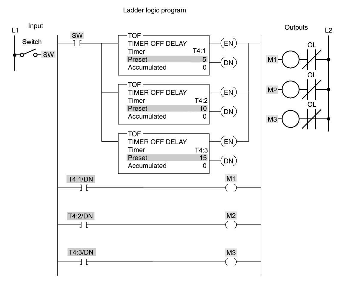
6. The program of Figure 7-22 is describe in the text and uses off-delay timers to switch motors off sequentially at 5 second intervals. Prepare an I/O connection diagram and ladder logic program for the process. Use addresses that apply to your PLC. Enter the program into the PLC and prove its operation.

Copyright (c) 2017 McGraw-Hill Education. All rights reserved. No reproduction or distribution without the prior written consent of McGraw-Hill Education. 27
Figure 7-21 Hardwired sequence control circuit for assignment 5.
To be completed by the student.
7. Prepare an I/O connection diagram and ladder logic program to execute the hardwired off-delay timer circuit shown in Figure 7-23. Enter the program into the PLC and prove its operation.
Copyright (c) 2017 McGraw-Hill Education. All rights reserved. No reproduction or distribution without the prior written consent of McGraw-Hill Education. 28
Figure 7-22 Off-delay timer program for assignment 6.
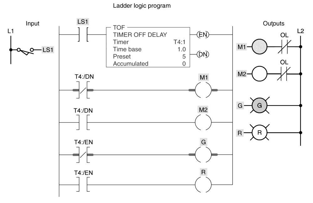
8. The program of Figure 7-24 is describe in the text and use an off-delay timer containing both instantaneous and timed contacts. Prepare an I/O connection diagram and ladder logic program for the process. Use addresses that apply to your PLC. Enter the program into the PLC and prove its operation.

Copyright (c) 2017 McGraw-Hill Education. All rights reserved. No reproduction or distribution without the prior written consent of McGraw-Hill Education. 29
Figure 7-23 Hardwired off-delay timer circuit for assignment 7. To be completed by the student.
Figure 7-24 Off-delay timer program for assignment 8.
To be completed by the student.
9. The program of Figure 7-25 is describe in the text and use both on-delay and off-delay timers as part of a fluid pumping process. Prepare an I/O connection diagram and ladder logic program for the process. Use addresses that apply to your PLC. Enter the program into the PLC and prove its operation.

Figure 7-25 Fluid pumping process program for assignment 9.
To be completed by the student.
10. Prepare an I/O connection diagram and ladder logic program to execute the retentive on-delay timer program shown in Figure 7-26. Enter the program into the PLC and prove its operation.
Copyright (c) 2017 McGraw-Hill Education. All rights reserved. No reproduction or distribution without the prior written consent of McGraw-Hill Education. 30
To
11. The program of Figure 7-27 is describe in the text and uses a retentive on-delay as part of an alarm program. Prepare an I/O connection diagram and ladder logic program for the process. Use addresses that apply to your PLC. Enter the program into the PLC and prove its operation.

To be completed by the student.

Copyright (c) 2017 McGraw-Hill Education. All rights reserved. No reproduction or distribution without the prior written consent of McGraw-Hill Education. 31
Figure 7-26 Retentive on-delay timer program for assignment 10.
be completed by the student.
Figure 7-27 Timer alarm program for assignment 11.
12. The program of Figure 7-28 is describe in the text and uses TON, TOF, and RTO timers as part of a bearing lubrication program. Prepare an I/O connection diagram and ladder logic program for the process. Use addresses that apply to your PLC. Enter the program into the PLC and prove its operation.
To be completed by the student.

32
Copyright (c) 2017 McGraw-Hill Education. All rights reserved. No reproduction or distribution without the prior written consent of McGraw-Hill Education.
Figure 7-28 Bearing lubrication program for assignment 12.
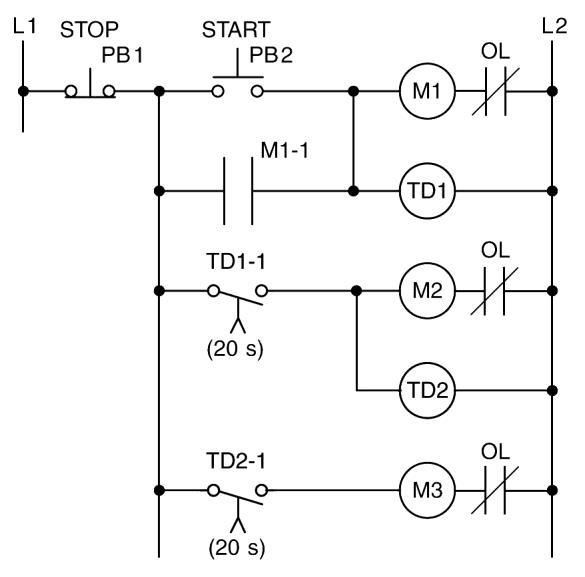
13. Prepare an I/O connection diagram and ladder logic program to execute the hardwired sequential time delayed motor starting circuit shown in Figure 7-29. Enter the program into the PLC and prove its operation.
Figure
Hardwired sequential delayed motor starting circuit for assignment 13.
To be completed by the student.
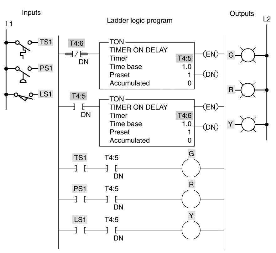
14. The program of Figure 7-30 is describe in the text and uses two interconnected TON timers to form an annunciator flasher program. Prepare an I/O connection diagram and ladder logic program for the process. Use addresses that apply to your PLC. Enter the program into the PLC and prove its operation.
Copyright (c) 2017 McGraw-Hill Education. All rights reserved. No reproduction or distribution without the prior written consent
Education. 33
of McGraw-Hill
7-29
To be completed by the student.
15. The program of Figure 7-31 is describe in the text and is used for control of traffic lights in one direction. Prepare an I/O connection diagram and ladder logic program for the process. Use addresses that apply to your PLC. Enter the program into the PLC and prove its operation
Copyright (c) 2017 McGraw-Hill Education. All rights reserved. No reproduction or distribution without the prior written consent of McGraw-Hill Education. 34
Figure 7-30 Annunciator flasher program for assignment 14.
To be completed by the student.
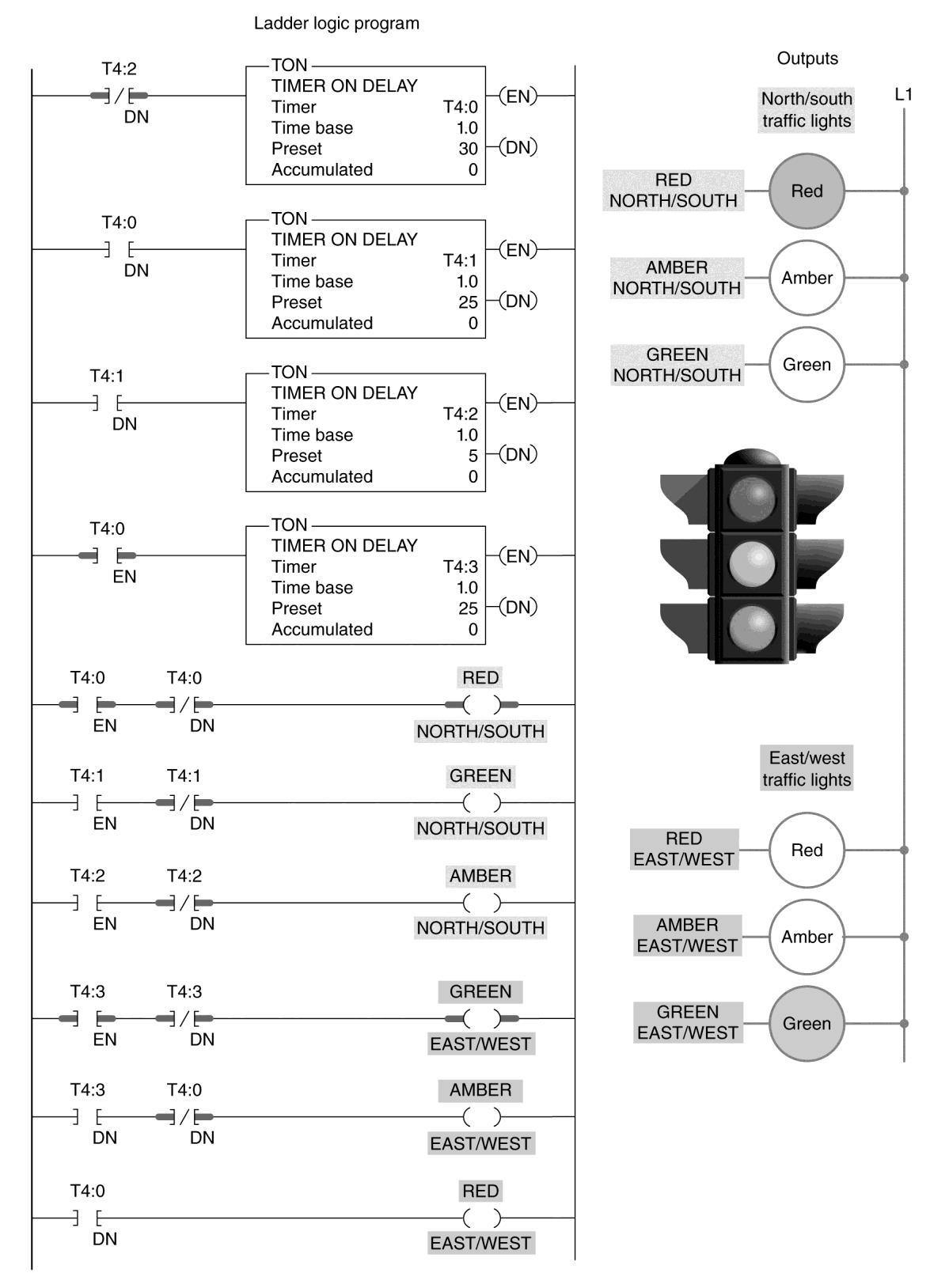
16. The program of Figure 7-32 is describe in the text and is used for control of traffic lights in two directions. Prepare an I/O connection diagram and ladder logic program for the process. Use addresses that apply to your PLC. Enter the program into the PLC and prove its operation

Copyright (c) 2017 McGraw-Hill Education. All rights reserved. No reproduction or distribution without the prior written consent of McGraw-Hill Education. 35
Figure 7-31 Traffic lights program for assignment 15.
Copyright (c) 2017 McGraw-Hill Education. All rights reserved. No reproduction or distribution without the prior written consent of McGraw-Hill Education. 36
Figure 7-32 Traffic lights program for assignment 16.
To be completed by the student.
17. Prepare an I/O connection diagram and ladder logic program for the hardwired automatic mixing process circuit shown in Figure 7-33. Enter the program into the PLC and prove its operation. The operation of the process can be summarized as follows.
• Process is initiated by pressing the start pushbutton PB2.
• Solenoid A is energized to allow fluid to flow into the tank.
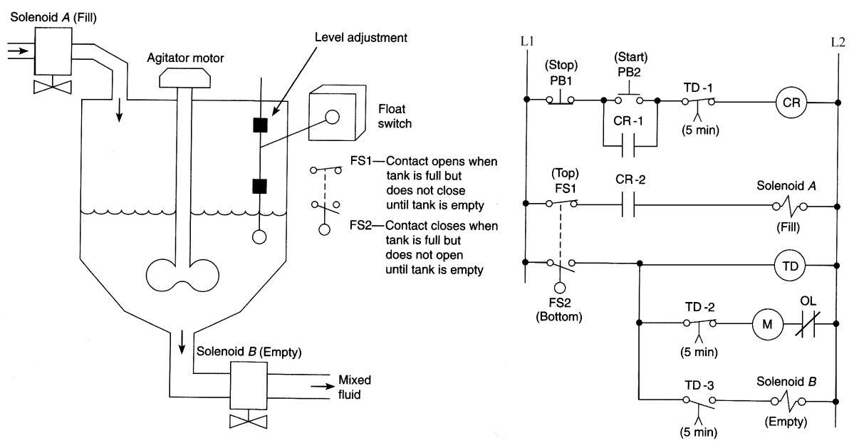
• Fluid flows in until the float switch is activated at the full position.
• Agitator motor is started and operates for 5 min and then stops.
• Solenoid B is energized to empty the tank.
• When the float switch is activated at the empty position, the process stops and is placed in the ready position for the next manual start.
Copyright (c) 2017 McGraw-Hill Education. All rights reserved. No reproduction or distribution without the prior written consent of McGraw-Hill Education. 37
Figure 7-33 Hardwired automatic mixing process for assignment 17. To be completed by the student.
18. Prepare an I/O connection diagram and ladder logic program for the hardwired motor control circuit shown in Figure 7-34. Enter the program into the PLC and prove its operation. The operation of the process can be summarized as follows.
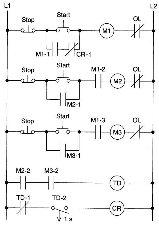
• The control process consists of three motors: M1, M2, and M3.
• The electrical control system is to be designed so that motor M1 must be running before motor M2 or M3 can be started.
• Each motor has its own start/stop pushbutton station.
• Both motors M2 and M3 can normally be stopped or started without affecting the operation of motor M1.
• However, if all three motors are running, the stopping of any one motor, for any reason, will automatically stop all three motors.
Copyright (c) 2017 McGraw-Hill Education. All rights reserved. No reproduction or distribution without the prior written consent of McGraw-Hill Education. 38
Figure 7-34 Hardwired motor control circuit for assignment 18.
To be completed by the student.
19. Write a PLC ladder logic diagram for a display sign that will sequentially turn on three lights 2 seconds apart, then turn all three lights off and repeat the sequence. Enter the program into the PLC and prove its operation.
To be completed by the student.
20. Write a PLC program that will turn on pilot light PL1 10 seconds after switch S1 is turned on. Pilot light PL2 will come on 5 seconds after PL1 comes on. Pilot light PL3 will come on 8 seconds after PL2 comes on. Pressing pushbutton PB1 will reset all the timers but only if PL3 is on. Enter the program into the PLC and prove its operation.
To be completed by the student.
22. When a switch is turned on, PL1 goes on immediately and PL2 goes on 9 seconds later. Opening the switch turns both lights off. Write a program that implements this process. Enter the program into the PLC and prove its operation.
To be completed by the student.
23. When a switch is turned on, PL1 and PL2 immediately go on. When the switch is turned off, PL1 immediately goes off. PL2 remains on for another 3 seconds and then goes off. Write a program that will implement this process. Enter the program into the PLC and prove its operation.
To be completed by the student.
Copyright (c) 2017 McGraw-Hill Education. All rights reserved. No reproduction or distribution without the prior written consent
McGraw-Hill Education. 39
of
24. When a switch is turned on, PL1 and PL2 immediately go on. PL1 turns off after 4 seconds. PL2 remains on until the switch is turned off. Turning the switch off at any time turns both lights off. Write a program that will implement this process. Enter the program into the PLC and prove its operation.
To be completed by the student.
25. A saw, fan, and lube pump all go on when a start button is pressed. Pressing a stop button immediately stops the saw but allows the fan to continue operating. The fan is to run for an additional 5 seconds after shutdown of the saw. If the saw has operated for more than 20 seconds, the fan should remain on until reset by a separate fan reset button. If the saw has operated less than 20 seconds, the lube pump should go off when the saw is turned off. However, if the saw has operated for more than 20 seconds, the lube pump should remain on for an additional 10 seconds after the saw is turned off. Write a program that will implement this process. Enter the program into the PLC and prove its operation.
To be completed by the student.
25) A lamp is required to turn on for 10 seconds each time a door is opened. Prepare an I/O connection diagram and ladder logic program that will perform this operation. Enter the program into the PLC, and prove its operation.
To be completed by the student.
Copyright (c) 2017 McGraw-Hill Education. All rights reserved. No reproduction or distribution without the prior written consent of McGraw-Hill Education. 40
26) A PLC program is required to control part of an industrial heating oven as follows:
• The system is activated by a Start button that seals in an internal control relay and is de-activated by pressing a Stop button.
• When the Start button is pressed, a TON timer will activate a warning buzzer which is on for 5 seconds and warns that the oven is about to start.
• After 5 seconds the buzzer stops and the heating coils for the oven are turned on for 10 minutes (600 seconds).
Prepare an I/O connection diagram and ladder logic program that will perform this operation. Enter the program into the PLC, and prove its operation.
To be completed by the student.
Copyright (c) 2017 McGraw-Hill Education. All rights reserved. No reproduction or distribution without the prior written consent of McGraw-Hill Education. 41
Programmable Logic Controllers 5th Edition Petruzella Solutions Manual Visit TestBankBell.com to get complete for all chapters
