


This 97-year-old bridge in Newport, near Cardiff, is the city's first heritage site to benefit from a council initiative to transition to energy-efficient LED lighting. Installed by Centregreat, the lighting will deliver 61% in energy savings, in line with Newport City Council's environmental goals and costsaving measures launched in 2021.
"This job was part of our contract with the council to maintain the street lights on the bridge," says Mike Marshall, Contract Manager at Centregreat, which hasitsHQinBridgend. "Wedothiswork all the time," he says of changing the lights from SON [sodium lamps] to LEDs.
f The four-lane bridge has 12 steel ] f ·a "' 8 columns -six on either side. Each column has three lanterns, one at the top illuminating the road and two lower ones lighting the footway.
Exterior lighting manufacturer Acrospire, which has worked with Centregreat on other projects, supplied the new lanterns. The company provided its 31 W Muirfield and 75 W Hexham luminaires -both made from aluminium and painted black. The Muirfield, a heritage post-top lantern, and the Hexham, inspired by Victorian gas lanterns, were selected for their authentic design and energy efficiency.
Using the 12 existing ornate columns and lantern arrangement, the new LED lighting solution has a 3,000 Kelvin colour temperature, which pays homage to the warm glow of the original gas lamps while delivering modern performance.
It took Centregreat about three days to replace the lanterns, using a mobile elevated working platform (or cherry

picker). The bridge stayed open during the installation. Traffic management to protect pedestrians was set up around each column, and the lane nearest the column being worked on was closed to traffic. It took two men two to three hours to upgrade each column.
"We had to replace the old lanterns with retro lamps as the original couldn't take the LEDs; the technology wasn't compatible," says Marshall.
About 15 years ago, Centregreat replaced the bronze embellishment kits that sat beneath the two lower lanterns on each column with a matching decorative element made from rubber and resin, because the originals were deteriorating.
"I think the upgraded lanterns look great and the LEDs should last for up to 20 years," Marshall adds.
NICEIC Technical Director
Paul Collins outlines significant developments in the industry, and the organisations working hard to help businesses adapt and thrive

The experience of learners, their tutors and employers


NICEICtraining is trusted by customers across the UK and provides the experience you need to take advantage of new opportunities.
We are committed to bringing you even more quality training programmes in electrical and renewable technologies, to support your business growth, build your skills and help you stay ahead of industry trends.
50+coursescoveringarangeoftopics. (V Electrical (v1>Renewabletechnology ~]'t>Emergencylighting,firedetectionandalarms A~ Businesssupport
Whenyoucangettrainingfromthemostrecognised certificationbodyintheUK,whygoanywhereelse?
©2024
ISSN 2042-5732 niceic.com

Enquiries 01582 539000
Communications manager: Debbie Shields debbie.shields@certsure.com
Customer services: 0333 015 6625
Sales: 0333 015 6626
Training: 0333 015 6627
Technical helpline: 0333 015 6628
Insurance: 0333 015 6629
@officialNICEIC
Published on behalf of Certsure by:
Think, 65 Riding House Street, London, WlW 7EH
Editor: Clare Dowdy clare.dowdy@thinkpublishing.co.uk
Group managing editor: Sian Campbell
Art director: Ian Hart
Associate director: Anna Vassallo
Client engagement director: Emma Godfrey
Content development director: Matthew Rock
Advertising: Tom Davison tom.davison@thinkpublishing.co.uk
Ben Sellers ben.sellers@thinkpublishing.co.uk
Connectionswelcomes ideas for contributions. Please email connections@thinkpublishing.co.uk
All rights reserved. This publication (and any part thereof) may not be reproduced, transmitted or stored in any format without the prior written permission of the publisher. Think Publishing Ltd accepts no liability for the accuracy of the contents or any opinions expressed herein.
Printed by Acorn Web Offset, West Yorkshire. Connectionsand its paper wrapper are printed on paper from European mills, meeting the
?EFC highest quality and environmental standards. Both the magazine and the paper wrapper are fully recyclable.
Welcome to the autumn issue of Connections magazine. The country has shifted considerably since our last issue, most notably with the change in government.
The electrical industry has also seen significant developments: Amendment 3:2024 has been published and has come into effect; proposed details for Amendment 4:2026 are now available for public comment; and the final Grenfell Tower Inquiry report emphasises the urgent need for reform. All this points to an exceptionally busy period for both the electrical industry and the wider building services sector.
This leads me to our cover story, which sets out to demystify who's who in the industry (page 33). Crucially, the article sheds light on what each of the leading organisations is doing behind the scenes to ensure the industry continues to progress and adapt to the changes happening around us. I strongly encourage you to take the time to read this report.
Returning to Amendment 4:2026 and the Draft for Public Consultation (DPC),
Findoutwhatthe industrybodiesare uptoonyour behalfPage33 Makesureyou commentonthe proposedchanges toAmendment 4:2026Page39 Refreshyourmemory onhowtobest prepareforyour assessmentPage
it's vital that you have your say on the proposed changes to the wiring regulations, set to be introduced in 2026. This is a major update, and details on how to provide your feedback are outlined in our news item on page 39.
Another important topic covered here is preparing for your NICEIC assessment (page 20). Whether you've been with us for one year or 25 years, it's always beneficial to refresh your understanding of the requirements and their rationale. Thorough preparation can help improve the assessment process, leaving plenty of time for valuable and productive conversations.
That's all from me for now. I hope you enjoy this issue, and don't forget to log any learnings on your CPD record as we will be asking to see it when we come to see you.
Paul Collins Technical Director, NICEIC


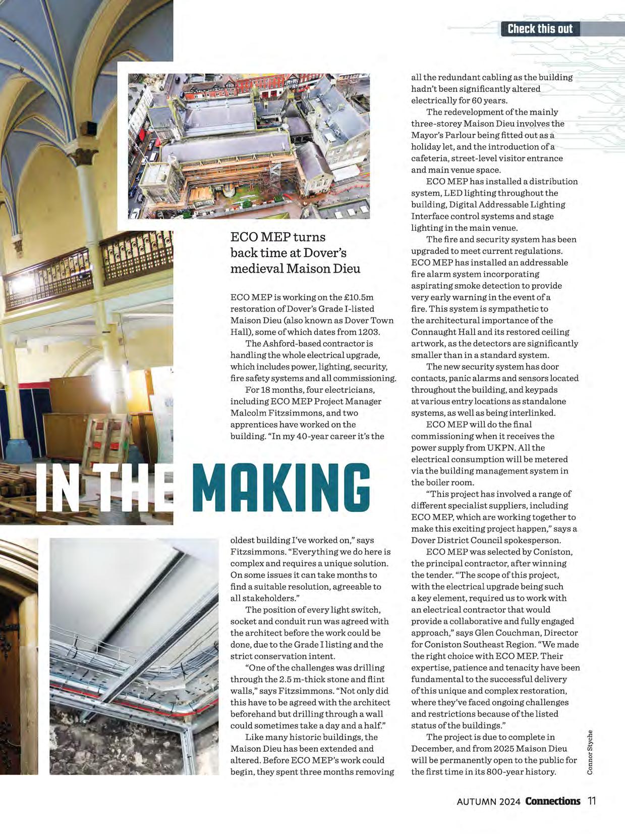
ECO MEP is working on the £10.5m restoration of Dover's Grade I-listed Maison Dieu (also known as Dover Town Hall), some of which dates from 1203.
The Ashford-based contractor is handling the whole electrical upgrade, which includes power, lighting, security, fire safety systems and all commissioning.
For 18 months, four electricians, including ECO MEP Project Manager Malcolm Fitzsimmons, and two apprentices have worked on the building. "In my 40-year career it's the
all the redundant cabling as the building hadn't been significantly altered electrically for 60 years.
The redevelopment of the mainly three-storey Maison Dieu involves the Mayor's Parlour being fitted out as a holiday let, and the introduction of a cafeteria, street-level visitor entrance and main venue space.
ECO MEP has installed a distribution system, LED lighting throughout the building, Digital Addressable Lighting Interface control systems and stage lighting in the main venue.
The fire and security system has been upgraded to meet current regulations.
ECO MEP has installed an addressable fire alarm system incorporating aspirating smoke detection to provide very early warning in the event of a fire. This system is sympathetic to the architectural importance of the Connaught Hall and its restored ceiling artwork, as the detectors are significantly smaller than in a standard system.
The new security system has door contacts, panic alarms and sensors located throughout the building, and keypads at various entry locations as standalone systems, as well as being interlinked.
ECO MEP will do the final commissioning when it receives the power supply from UKPN. All the electrical consumption will be metered via the building management system in the boiler room.
oldest building I've worked on," says Fitzsimmons. "Everything we do here is complex and requires a unique solution. On some issues it can take months to find a suitable resolution, agreeable to all stakeholders."
The position of every light switch, socket and conduit run was agreed with the architect before the work could be done, due to the Grade I listing and the strict conservation intent.
"One of the challenges was drilling through the 2.5 m-thick stone and flint walls," says Fitzsimmons. "Not only did this have to be agreed with the architect beforehand but drilling through a wall could sometimes take a day and a half."
Like many historic buildings, the Maison Dieu has been extended and altered. Before ECO ME P's work could begin, they spent three months removing
"This project has involved a range of different specialist suppliers, including ECO MEP, which are working together to make this exciting project happen," says a Dover District Council spokesperson.
ECO MEP was selected by Coniston, the principal contractor, after winning the tender. "The scope of this project, with the electrical upgrade being such a key element, required us to work with an electrical contractor that would provide a collaborative and fully engaged approach," says Glen Couchman, Director for Coniston Southeast Region. "We made the right choice with ECO MEP. Their expertise, patience and tenacity have been fundamental to the successful delivery of this unique and complex restoration, where they've faced ongoing challenges and restrictions because of the listed status of the buildings."
The project is due to complete in December, and from 2025 Maison Dieu will be permanently open to the public for the first time in its 800-year history.
Getting the basics of customer service right is an important part of building your business. There are clear links between customer satisfaction, revenue growth and profitability, according to the Institute of Customer Service (!CS).
In its latest UK Customer Satisfaction Index, the !CS found that "31%of customers would be willing to pay more to ensure they get excellent service." That's slightly lower than a year ago but 5% more than in 2020.
In parts of the country with a high density of electrical contractors all charging a similar day rate, how do you stand out from the crowd?
Customers often go on the three Rs -reviews, ratings and referralswhere a key component is customer service, says Certsure's Head of Customer Experience, Lucy Lowrie.

Practical elements that need to be right include "how you book in a job and arrange the time to visit the property, and if the context of the job changes, how you keep the customer updated", says Lowrie, who has also held senior customer service roles atAsos, Philips and Vodafone.
"It's always about the relationship skills of the electrical contractor," she adds. "Are they helpful and straightforward? Do they inspire confidence, and maintain communication throughout the job?" And crucially, it's then about encouraging the customer to give feedback, to ensure the quality of the job meets their expectations.
Joanna Causon, Chief Executive of the ICS, backs this up. "In many cases, the way organisations demonstrate care and understanding for a customer's personal needs and situation happens in the moment, through an employee's empathy, behaviour and responsiveness," she says in the Customer Satisfaction Index report.
"This underlines the importance of a constant focus on organisational culture
and developing the skills, behaviours and knowledge that lead to differentiated service experiences."
If all the customer service boxes are ticked, this should become a virtuous cycle. If not, then it can have the opposite effect because service failures and problems come with a cost, according to the index. That cost is the time employees waste dealing with the consequences of their organisation getting something wrong for a customer.
"The aspects of personal care and service most valued by customers are an organisation being available when needed, clarity and relevance of information and proactive contact," says Causon in the index.
"31%ofcustomerswould bewillingtoaymore toensuretheyget

• Whensomeone is a newcustomer,hawQuickly canyoufallowup?Hawdoyouexplainta them howyouworkandhawyoucanhelpthem? If you'rebusyandtheyneedanurgentjab,doyou havea networkof trustedtradespeople youcanreferthemta?
• Vauareyourbrand - decidewhatyouwantyour serviceofferingor paintof differenceta be,and ensurethatall yourinteractionsalignwiththese principles.[Sameimportantbehavioursareto be: honest,reliableanddependable,neatandtidy, proactiveandfriendly.]
• Ensureyoukeepyourpromises.
• Keepyourcustomerupdated.Ongoingdialogueis crucial.If thingschange,let themknowearlyand offeralternatives,andincludeimpact,optionsand casts.
• Askfor feedback-it's a greatwayta getyour customerratingsupandwill alsoallowyouta nip in thebudanyissuesthat mightbeshared.
• Provide a guaranteeorcaverperiodandexplain whatthis means.
• Shareuserstarterguides,taptipsandhawta monitor neweQuipment ta ensure it worksproperly.
• Considerhawta makeanyactivitiesthecustomer needsta doaseasyaspossible. Farexample,far makinga payment,createa way for themta makeananlinepaymentthrougha link.
• Keepyourcool,evenif thingsbecamefrayedor tense.Considerhawa differentapproachcouldget therelationshipbackantrack.
Farmaregoadideasfar thesaletrader,gota www.instituteafcustamerservice.com
• Business ta businessrelationships at a small ta mediumenterpriselevelwlllusuallyhavean accountmanagementlayerthatmanagesthe relationshipandbringstogetherthecustomerand theproductorservicewithanoverlay.
• Accountmanagementandthenthecustomer supportthatsitsbehindthisis criticalin managing a positive,proactiveandtrustedrelationshipwell.
• TheremaybemaredefinedKPlsandstandards agreed,potentiallywithbonusesorpenalties if the productorserviceslipsin anyway.
Farmaregoadideasfar SMEs,gota www.instituteafcustamerservice.com

By Charles Orton-Jones
The joys of self-employment are abundant. The freedom. The opportunity to keep all the profit. And the thrill of being the boss of your own enterprise. But those first years in business can be intimidating, and not all start-ups survive.
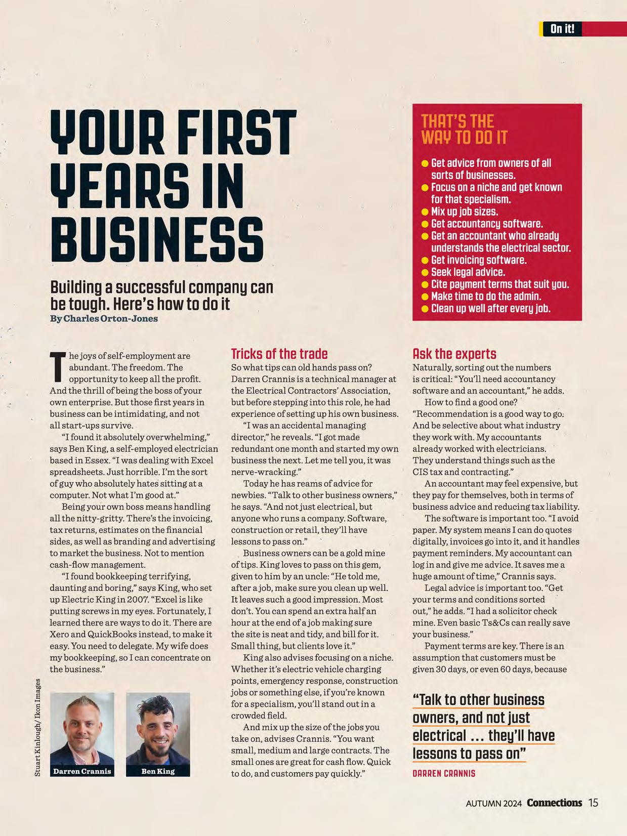
"I found it absolutely overwhelming," says Ben King, a self-employed electrician based in Essex. "I was dealing with Excel spreadsheets. Just horrible. I'm the sort of guy who absolutely hates sitting at a computer. Not what I'm good at."
Being your own boss means handling all the nitty-gritty. There's the invoicing, tax returns, estimates on the financial sides, as well as branding and advertising to market the business. Not to mention cash-flow management.
"I found bookkeeping terrifying, daunting and boring," says King, who set up Electric King in 2007. "Excel is like putting screws in my eyes. Fortunately, I learned there are ways to do it. There are Xero and QuickBooks instead, to make it easy. You need to delegate. My wife does my bookkeeping, so I can concentrate on the business."
So wh!J,ttips can old hands pass on?
Darren Crannis is a technical manager at the Electrical Contractors' Association, but before stepping into this role, he had experience of setting up his own business.
"I was an accidental managing director," he reveals. "I got made redundant one month and started my own business the next. Let me tell you, it was nerve-wracking."
Today he has reams of advice for newbies. "Talk to other business owners," he says. "And not just electrical, but anyone who runs a company. Software, construction or retail, they'll have lessons to pass on."
. Business owners can be a gold mine of tips. King loves to pass on this gem, given to him by an uncle: "He told me, after a job, make sure you clean up well. It leaves such a good impression. Most don't. You can spend an extra half an hour at the end of a job making sure the site is neat and tidy, and bill for it. Small thing, but clients love it."
King also advises focusing on a niche. Whether it's electric vehicle charging points, emergency response, construction jobs or something else, if you're known for a specialism, you'll stand out in a crowded field.
And mix up the size of the jobs you take on, advises Crannis. "You want small, medium and large contracts. The small ones are great for cash flow. Quick to do, and customers pay quickly."
• Getadvicefromownersofall sortsofbusinesses.
• Focusonanicheandgetknown forthatspecialism.
• Mixupjobsizes.
• Getaccountancysoftware.
• Getanaccountantwhoalready understandstheelectricalsector.
• Getinvoicingsoftware.
• Seeklegaladvice.
• Citepaymenttermsthatsuityou.
• Maketimetodotheadmin.
• Cleanupwellaftereveryjob.
Naturally, sorting out the numbers is critical: "You'll need accountancy software and an accountant," he adds. How to find a good one? • "Recommendation is a good way to go, And be selective about what industry they work with. My accountants already worked with electricians. • They 1,mderstand things such as the CIS tax and contracting." . An accountant may feel expensive, but they pay for themselves, both in terms of business advice and reducing tax liability.
The software is important too. "I avoid paper. My system means I can d~ quotes digitally, invoices go'into it, and it handles payment reminders. My accountant can log in and give me advice. It saves me a huge amount of time," Crannis says.
Legal advice is important too. "Get your terms and conditions sorted • out," lie adds. "I had a soHcitor check mine. Even basic Ts&Cs can really save your business."
Payment terms are key. There is an assumption that customers must be given 30 days, or even 60 days, because
"Talktootherbusiness owners,andnotjust electrical ... they'llhave lessonstopasson" DARRENCRANNIS
DARRENCRANNIS
that's what large enterprises can abso_rb. But it is perfectly acceptable to cite 14 days or even immediate payment. That'.s the beauty of being the bossyo_uget to decide.
Maybe the trickiest aspect is the admin. Owning a company means wearing two hats: boss and worker. A consistent theme from those who've had success is to make time to work on your business, not just in it.
"When I ran my own business, I did my admin on Wednesdays," says Crannis. ''.Ispent the morning doing marketing and networking. And in the afternoon I sorted out my paperwork. I did that from the start and it worked for me. If you don't set aside time for admin you'll lose money over the long run."
There are many online resources for business owners (see below).
Tempted? "Every successful business, no matter how well run it is now, started off as a person or couple of peoJ:)lein a garage sqmewhere," says King. "Many electrical businesses start small. Just • bite off what you can chew, and you'll keep growing. It's not as difficult as you think."
• Startups.co.uk is popularwith first-timers.It offersadvicefrom entrepreneursandexperts,and hasnopaywall.
• HMRCrunsfreelivewebinarson keepingbusinessrecords,filling in tax returns,andincomeand tax reliefs.
• TheOpenUniversityrunsa coursecalled'Entrepreneurshipfromideasto reality',againfree of charge.
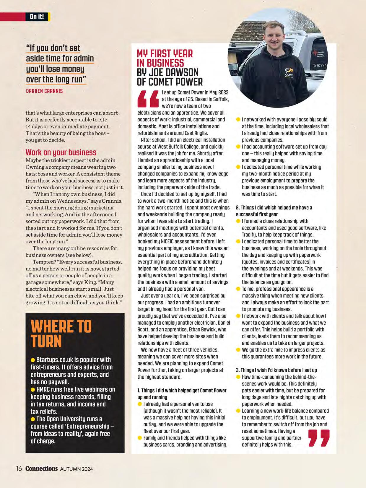
I setupCometPowerin May8083 at theageof 85.Basedin Suffolk, we'renowateamof two electriciansandanapprentice.Wecoverall aspectsof work:industrial,commercialand domestic.Mostis officeinstallationsand refurbishmentsaroundEastAnglia.
Afterschool, I didanelectricalinstallation courseat WestSuffolkCollege,andQuickly realised it wasthejobfor me.Shortlyafter, I landedanapprenticeshipwitha local companysimilarto mybusinessnow. I changedcompanies to expandmyknowledge andlearnmoreaspectsoftheindustry, includingthepaperworksideof thetrade.
OnceI'ddecidedto set upbymyself, I had to worka two-monthnoticeandthis is when the hardworkstarted.I spentmostevenings andweekendsbuildingthecompanyready for whenI wasableto starttrading. I organisedmeetingswith potentialclients, wholesalersandaccountants.I'deven bookedmyNICEICassessmentbefore I left mypreviousemployer,asI knewthiswasan essentialpartof myaccreditation.Getting everythingin placebeforehanddefinitely helpedmefocusonprovidingmybest QualityworkwhenI begantrading. I started the businesswith a smallamountof savings andI alreadyhada personalvan.
Justovera yearon,I'vebeensurprisedby ourprogress. I hadanambitiousturnover targetin myheadforthefirst year.ButI can proudlysaythatwe'veexceeded it. I'vealso managed to employanotherelectrician,Daniel Scott,andanapprentice,EthanBewick,who havehelpeddevelopthebusinessandbuild relationshipswithclients.
Wenowhavea fleetof threevehicles, meaningwecancovermoresiteswhen needed.Weareplanningto expandComet Powerfurther,takingonlargerprojectsat the higheststandard.
l. Things I didwhichhelpedgetCometPower upandrunning
• I alreadyhada personalvanto use (although it wasn'tthemostreliable). It wasa massivehelpnothavingthisinitial outlay,andwewereableto upgradethe fleetoverourfirst year.
• Familyandfriendshelpedwiththingslike businesscards,brandingandadvertising.
• I networkedwitheveryone I possiblycould at thetime,includinglocalwholesalersthat I alreadyhadcloserelationshipswithfrom previouscompanies.
• I hadaccountingsoftwaresetupfromday one-this reallyhelpedwithsavingtime andmanagingmoney.
• I dedicatedpersonaltimewhileworking mytwo-monthnoticeperiodat my previousemployment to preparethe businessasmuchaspossibleforwhenit wastimeto start.
I!.Things I didwhichhelpedmehavea successfulfirst year
• I formeda closerelationshipwith accountantsandusedgoodsoftware,like Tradify,to helpkeeptrackof things.
• I dedicatedpersonaltimeto betterthe business,workingonthetoolsthroughout thedayandkeepingupwithpaperwork (Quotes,invoicesandcertificates)in theeveningsandat weekends.Thiswas difficultat thetimebutit getseasierto find thebalanceasyougoon.
• Tome,professionalappearance is a massivethingwhenmeetingnewclients, andI alwaysmakeaneffortto lookthepart to promotemybusiness.
• I networkwithclientsandtalkabouthowI wantto expandthebusinessandwhatwe canoffer.Thishelpsbuilda portfoliowith clients,leadsthemto recommending us andenablesusto takeonlargerprojects.
• Wegotheextramileto impressclientsas thisguaranteesmoreworkinthefuture.
3.Things I wishI'dknownbefore I setup
• Howtime-consumingthebehind-thescenesworkwouldbe.Thisdefinitely getseasierwithtime,butbepreparedfor longdaysandlatenightscatchingupwith paperworkwhenneeded.
• Learning a newwork-lifebalancecompared to employment.It's difficult,butyouhave to remember to switchoff fromthejoband resetsometimes.Having a ' ' supportivefamilyandpartner definitelyhelpswiththis.
When it comes to health and safety (H&S) hitting the headlines, there are some horror stories out there. Take the tragic case of an 18-year-old electrical apprentice in Moneymore, Northern Ireland. Earlier this year, Londonderry Crown Court fined his employer, Swift Control Services (not NICEIC-certified), £10,000 after he suffered fatal injuries in 2021. He had come into contact with a live electrical circuit in a storeroom in the property while he was working alone and unsupervised.
By Helen Parton

There has been a rise in safety-related electrical incidents in the last few years, with the number of fatalities reported to the Health and Safety Executive up from four in 2018/2019 to nine in 2021/2022. Meanwhile 'other events', which include any short-circuit or overload, rose from nearly 15,000 to over 17,750 in the same period.
Handling injuries and working from height are two of the most common H&S hazards in the construction industry, with slips, trips and falls accounting for most accidents, says Tony Sidwell, Head of
Health and Safety and Environment at the Electrical Contractors' Association (ECA). "Injuries that are typically specific to electrical work include electric shock, electrical burns, muscular injuries and thermal burns."
Eloise Byrne, Specialist Adviser at the Institution of Occupational Safety and Health (IOSH), adds to the hazards list: "Injury from exposure to arcing, fire from faulty electrical equipment or installations and explosions caused by unsuitable electrical apparatus. Overhead and buried power lines at a construction site can also be hazardous as they carry a very high voltage."
A lot ofH&S issues can be headed off before they happen, with some pre-emptive planning. And as Certsure's Health, Safety & Environment Manager, Laura Southern, points out: "All NICEICcertified businesses can access our Pocket Guide app, which has lots of useful information." (See page 29.)
For Southern, you can't beat a back-to-basics approach to keep everyone safe. "Key things are planning your work, making sure you've looked at the HSE's five steps to risk assessment." This checklist covers identifying hazards, assessingthe risks, controlling the risks, recording your findings and reviewing the controls.
"Don't become complacent," she warns. "One day you could be going to a domestic property and another day you could be on a commercial construction site. Every site could be different and environments are changing so you may need to adapt."

Sidwell at ECA echoes this. "Too often the working environment is overlooked. This is where the majority of serious hazards are present, like working at height and confined spaces. Once completed, the risk assessment must be communicated to all relevant parties and reviewed on a regular basis or following any accidents."
IOSH's Byrne also highlights the importance of clear dialogue. "An effective two-way communication with workers on-site and any others who could be impacted by the work is one of the factors that electrical contractors should consider."
It's also about ensuring that equipment is safe, "that tools are maintained, clean and fit for purpose, and that equipment has been tested for electrical safety", she adds. And, of course, the electricity must be turned off before work is started and suitable measures must be in place where required to make sure it is not turned back on -this could be via a lock-out/ tag-out process.
GoodH6Sisnotjustrequiredbylaw, it'sgoodforbusinessbecause:
• Itmitigatesrisk,reducingtherisk offinesduetolackofcompliance withlegalobligations.
• Itincreasesemployeeretention andsatisfaction-arobust healthandsafetypolicyshows youcareasanemployer.
• Itshowsyou'reinnovative: you'reopentocontinuously improvingyourpractices,leading tobetterworkplaceconditions.
PoorH6Sisbadforbusiness:
• Itcouldmeanincreasedcosts intermsoflegalfees, compensationclaimsand increasedinsurancepremiums.
• Productivitycouldfallbecause ofyourstafffeelingunsafe, nottomentionabsenteeism as aresultofanyaccidentsand resultinginjuriesatwork.
• Vourreputationasaservice providercouldsufferifword spreadsthatyourH6Sisnot uptoscratchandpotential customerslosetrust.
Making sure you're insured is crucial. NICEIC Insurance Services arranges personal accident and short-term income protection policies. There are two levels of cover, either £250 or £500 per week benefit for loss of earnings. NICEIC Insurance Services Team Manager Rosie Tankard says: "The insurance not only provides cover in the event of a workplace accident, but extends to accidents outside of work too -for example, while playing sport. There is the option to add sickness should you be out of work due to illness, rather than accident." For more info go to www.niceicinsurance.com/terms-and-conditions.
Summing up the secret to good health and safety, Tony Sidwell stresses: "Human vigilance and positive behaviours will always play a vital part in keeping people safe in the electrical sector and all other industries and workplaces."
Smithexplains whysupervision andrecordkeepingareso importantinmeetingNICEIC schemereciuirements
Providing records of supervision is an NICEIC electrotechnical scheme requirement. It's to make sure that all electrical work is adequately and appropriately supervised. Your records demonstrate that you're meeting these requirements. They're evidence that you're managing your electrical work responsibly.
For businesses, reviewing supervision and training records can help you reduce your operating risk. And evidence of compliance can give customers confidence in you and your business.
The Principal Duty Holder (PDH) and the Qualified Supervisor (QS) are responsible for ensuring that all electrical work is adequately supervised. It's crucial for upholding high standards and protecting your business from potential liabilities.
The PDH is responsible for making sure there are systems in place so that all electrical work is carried out by competent persons who are adequately and appropriately supervised.
The QS is the technical representative for the certified business and is responsible for day-to-day safety, and the technical standard and quality of the electrical
work carried out under their supervision. The QS is responsible for identifying supervision requirements appropriate to the volume and complexity of your operations. That means ensuring all operatives are adequately supervised and being able to demonstrate how the ratio for supervision is determined, recorded and monitored. It's not one size fits all.
Your business must provide evidence that all personnel -whether directly employed, temporary, agency, subcontracted, self-employed or sole trader -are adequately supervised for the electrical work they undertake.
During your NICEIC management systems review (commonly known as the office audit) your assessor reviews evidence that all employed persons are competent and/ or adequately supervised for the electrical work they're undertaking.
Ensuring adequate supervision isn't simply about how many operatives you have on site. It's about considering what risk the work presents and who's undertaking those tasks. Are they competent to do

them? Do they have the Skills, Knowledge, Experience and Behaviours (SKEB)?
Determining the degree of supervision is based on the overall risk, which is determined by the level of operative and the degree of risk presented by the electrical work being undertaken.
l. Identify the level (one, two or three) of the operative appointed to carry out the electrical work (see table 1).
il. Identify the degree ofrisk (low, medium or high) based on table 2 and/or gain more detailed knowledge of the work to be carried out.
3. Cross reference the above items and identify the colour code in the risk matrix (green, amber and red).
4. Based on the colour code in table 3 and using table 4, identify what would be considered satisfactory in terms of (a) operative instruction, (b) inspector/ tester competence, and (c) involvement ofQS on site.
Based on the Electrotechnical Assessment Specification (EAS) and in
Table l LevelofOperativeAppointed OPEl!IITIVELEVELGUIOIINCE
LEVEL 1 Employed Persons would be Instructed persons (electrically) who would generally be apprentices, labourers, electrician's mates or electrical improve rs -and who, under the supervision of a Skilled person (electrically), could be able to install wiring systems. Others that fall within this category are career changers, who may have training and/or qualifications but lack experience.
LEVEL 8 Employed Persons would be Instructed persons (electrically) who are experienced, trusted electrical installers who can carry out Electrotechnical work efficiently and in accordance with the current BS 7671 and Building Regulations/Standards. Therefore, they can be expected to work most of the time without the need of close and detailed supervision.
LEVEL 3 Employed Persons would be considered as Skilled persons (electrically) who possess practical, theoretical and electrical engineering skills, experience and knowledge with adequate technical supervisory experience comparable to that of a Qualified Supervisor.
Table2DegreeofRiskintheElectrotechnicalWorkCoveredbyBS76n
Electrical work where the installation is isolated when not under LOW the control of the installer. Examples: First fix Electrotechnical work. Second fix Electrotechnical work.
Electrical work defined in BS 7671 as Minor Works in an unoccupied building -subject to safe isolation procedures documented and implemented.
Electrical work defined in BS 7671 as Minor Works in an occupied building -subject to safe isolation procedures documented and implemented.
All other Electrotechnical work, whether or not it is subject to safe isolation procedures.
Electrical work -Periodic Inspection and Testing.
Table3RiskMatrix
Level 1 Operative (instructed person: apprentice, improver, electrician's mate)
Level 2 Operative (instructed person: experienced, trusted)
Level 3 Operative (skilled person: equivalent to QS without role or qualification)
Inthesummer2084issueof Connections,weexploreddoing anddocumentingcontinuing professionaldevelopment. In ourwinter8024issue,we'll delveintoMCS.
turn the NICEIC electrotechnical scheme, NICEIC has provided guidance and associated tables and matrices in line with the EAS to help take the PDH and QS through these four key steps. The four tables show examples of the levels of operative (level 1, 2 and 3) and offer guidance on what types of work might be considered as a low, medium or high risk. They go on to show how to calculate the risk factor (using a traffic light risk matrix) and how to use this to help determine adequate supervision levels based on the risk factors.
As a business you're doing this already. Youknow which operatives you send out to do certain jobs. But this is about documenting and record-keeping as an evidence-based rationale so you can take a step back and look at your process and say: 'Hold on a minute, am I sending the right person?' That will help protect your business by making sure the electrical work your business is undertaking has been adequately and appropriately supervised.
If something goes wrong on site, you can demonstrate the business has undertaken this process. You can show the thought process behind your decisions; you haven't just put numbers on site, regardless of the type of work. So, the recording element, which can sometimes be overlooked, is key.
"Reviewinoursuerv1smn,
traininprocessesand recordsreallycanhell) mitiateourbusiness's oeratinrisks.Italsohels theOSbyensuringtheir responsibilitiesarebein metandmaintained"
The final step (table 4) is really important in understanding the QS's perspective. The level of operative you've assigned to the level ofrisk that you expect affects the level of supervision you have to provide to that individual. Because the higher the risk, the more involvement the QS needs to have on site.
Reviewing your supervision, training processes and records really can help mitigate your business's operating risks. It also helps the QS by ensuring their responsibilities are being met and maintained, giving them peace of mind that they have the right people on the right jobs, and they're being adequately supervised.
For NICEIC-certified businesses there's a free supervision template to download from our website (see below). It's essential to have a system in place. By following these steps and using the provided resources, you can effectively manage supervision, reduce risks and demonstrate compliance.
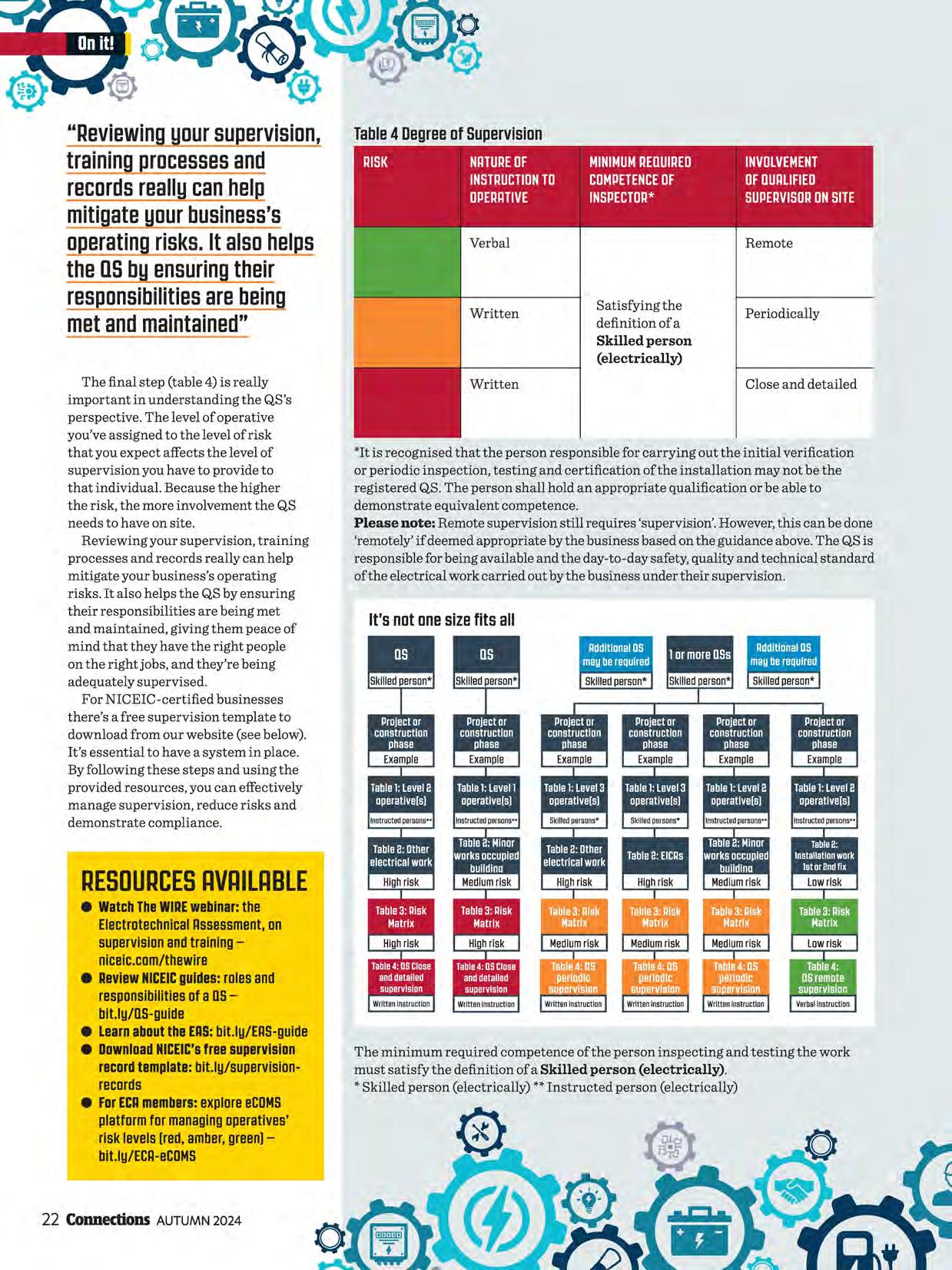
Satisfying the definition of a Skilled person (electrically)
Periodically
Close and detailed
*It is recognised that the person responsible for carrying out the initial verification or periodic inspection, testing and certification of the installation may not be the registered QS. The person shall hold an appropriate qualification or be able to demonstrate equivalent competence.
Please note: Remote supervision still requires 'supervision'. However, this can be done 'remotely' if deemed appropriate by the business based on the guidance above. The QS is responsible for being available and the day-to-day safety, quality and technical standard of the electrical work carried out by the business under their supervision.
eWatchTheWIAEwebinar:the ElectrotechnicalAssessment, on supervisionandtrainingniceic.com/thewire
• ReviewNICEICguides:rolesand responsibilitiesofaOSbit.ly/0S-guide
eLearnabouttheEAS:bit.ly/EAS-guide
• DownloadNICEIC'sfreesupervision recordtemplate:bit.ly/supervisionrecords
• ForECAmembers:exploreeCDMS platformformanagingoperatives' risklevels(red,amber,green)bit.ly/ECA-eCOMS
The minimum required competence of the person inspecting and testing the work must satisfy the definition of a Skilled person (electrically).
* Skilled person (electrically) **Instructed person (electrically)

BUILT TO LAST, LIGHTING THE WAY
THENEW,ROBUSTOUTDOOR FLOODLIGHTSFORANYWEATHER
The new standard for demanding outdoor applications: The FLOODLIGHT GEN 4 range is extremely efficient and very durable. Thanks to MULTI LUMEN, the brightness can be adapted to requirements. Sensor and Photocell versions add a further layer of versatility. Reliable even in the harshest conditions thanks to the waterproof cable gland, breather membrane, C4 corrosion resistance and up to IP66 and IK08. FLOODLIGHT GEN 4 are easy to install and come with a comprehensive 5-year guarantee.
Givingyouaccesstotheindustry's besttechnicalmindsandresources.
Technicalhelpline for expert support with installations, compliance and products.
~'(\\ NICEICPocketGuidesapp with 37+ technical guides.
CPDresourcesincluding THE WIRE webinars, NICEICevents, quarterly Connections magazine and live Q&As.
In-personandonlinetraining for core topics and new technologies.
Regularassessmentsto help you stay compliant, with guidance and technical advice.
NICEICOnlineCertificationSystem
-saving you time and money by selfcertifying your work and completing and sending certificates and reports. Cg;0
Savingson specialist, tailored trade insurance.
Discountson branded NICEICworkwear and tools in our online shop and 10% t@ off selected purchases at Tradepoint.
badge.
Drivingdemandfromcustomers.
Nationalmarketingcampaignsto raise public awareness of the high standards of NICEIC-certified businesses.
'FindatrustedNICEICtradesperson' tool to drive demand for your services.
Opening-upopportunities with specifiers such as facilities businesses, landlords and housing associations.
Representingyouintheindustry.
Communicatingyourvoice and influencing government and sector bodies through our role on industry committees.
Shapingfuturepolicyandregulations informed by your feedback.
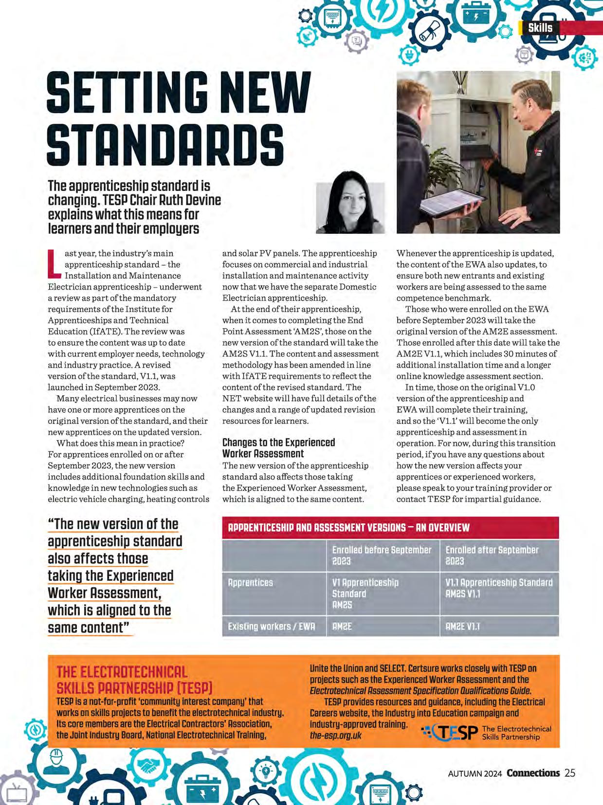
Theapprenticeshipstandard is changing.TESPChairRuthDevine explainswhatthismeansfor learnersandtheiremployers
Last year, the industry's main apprenticeship standard -the Installation and Maintenance Electrician apprenticeship -underwent a review as part of the mandatory requirements of the Institute for Apprenticeships and Technical Education (IfATE). The review was to ensure the content was up to date with current employer needs, technology and industry practice. A revised version of the standard, Vl.1, was launched in September 2023.
Many electrical businesses may now have one or more apprentices on the original version of the standard, and their new apprentices on the updated version. What does this mean in practice? For apprentices enrolled on or after September 2023, the new version includes additional foundation skills and knowledge in new technologies such as electric vehicle charging, heating controls
"Thenewversionofthe
and solar PV panels. The apprenticeship focuses on commercial and industrial installation and maintenance activity now that we have the separate Domestic Electrician apprenticeship.
At the end of their apprenticeship, when it comes to completing the End Point Assessment 'AM2S', those on the new version of the standard will take the AM2S Vl.1. The content and assessment methodology has been amended in line with IfATE requirements to reflect the content of the revised standard. The NET website will have full details of the changes and a range of updated revision resources for learners.
The new version of the apprenticeship standard also affects those taking the Experienced Worker Assessment, which is aligned to the same content.
Whenever the apprenticeship is updated, the content of the EWA also updates, to ensure both new entrants and existing workers are being assessed to the same competence benchmark.
Those who were enrolled on the EWA before September 2023 will take the original version of the AM2E assessment. Those enrolled after this date will take the AM2E Vl.1, which includes 30 minutes of additional installation time and a longer online knowledge assessment section.
In time, those on the original Vl.0 version of the apprenticeship and EWA will complete their training, and so the 'Vl.1' will become the only apprenticeship and assessment in operation. For now, during this transition period, if you have any questions about how the new version affects your apprentices or experienced workers, please speak to your training provider or contact TESP for impartial guidance.
Isanot-for-profit'communityInterestcompany'that worksonsklllsprojectstobenefittheelectrotechnlcalIndustry. ItscoremembersaretheElectricalContractors'Association,
Ourmonthlye-newsletterdeliversalltheinformationyou needtokeepup-to-datewiththeelectrotechnicalindustry.
Carefully curated each month to bring you and your team the most relevant and up-to-date information on the topics that matter most. You can expect to receive information such as:
• industrynews
• regulationchanges
• technicalinsights
• upcomingevents
• essentialcertificationupdates.
Thisemailissenttoqualifiedsupervisorsandprincipal dutyholders.
As an exclusive new benefit of certification with NICEIC,this e-newsletter does the hard work for you, so you can keep your finger on the pulse.
Want to learn more about recent amendments and industry developments?
Have a read of our latest issue.


Martin White of Whites Electrics in Canterbury found this when he was installing a new light fitting in a house extension. "The previous installer had fitted an extractor fan to the light via connector blocks with no enclosure or sleeving used." This was reconnected via a junction box and made safe.
Infutureissues,wewanttofeature yourgreatrepairworkalongside thebotchedjobs.Pleasesend beforeandafterphotosto
Steve Trotman ofTrotmanElectrical Services in Essex attended a callout because the customer could smell burning. He found this fault in the shower isolator. "When I asked who had installed this for them, I got the answer, 'Oh, my mate said he could do it for me'." Trotman fixed it by doing full insulation tests to make sure the cable was not damaged beyond use. "I then cut back all damaged cable, replaced the back box correctly, fitted a new isolator switch and terminated the cables correctly, and tested."
Phil Jones of PRJ Electrical Services in Inverness was completing an EI CR on a domestic property, when he found that the consumer unit had been doctored to fit a solid neutral conductor which was not designed for the unit. "I discussed the issue with my customer who agreed that I should fit anew consumer unit with RCBOs and surge protection."

HowthePocketGuidesappcan makeyourelectricalinstallation tasksthatbiteasier
The award-winning NICEIC Pocket Guides app is free to download for NICEIC-certified businesses. It's packed with information and tools, including:
• 38 Electrical Pocket Guides
• eight Gas Pocket Guides
• five easy-to-use calculators
• links to useful industry information sources
Adiabaticequation calculator
A handy way to determine the minimum cross-sectional area for circuit protective conductors based on the requirements of BS 7671 and using the adiabatic equation.
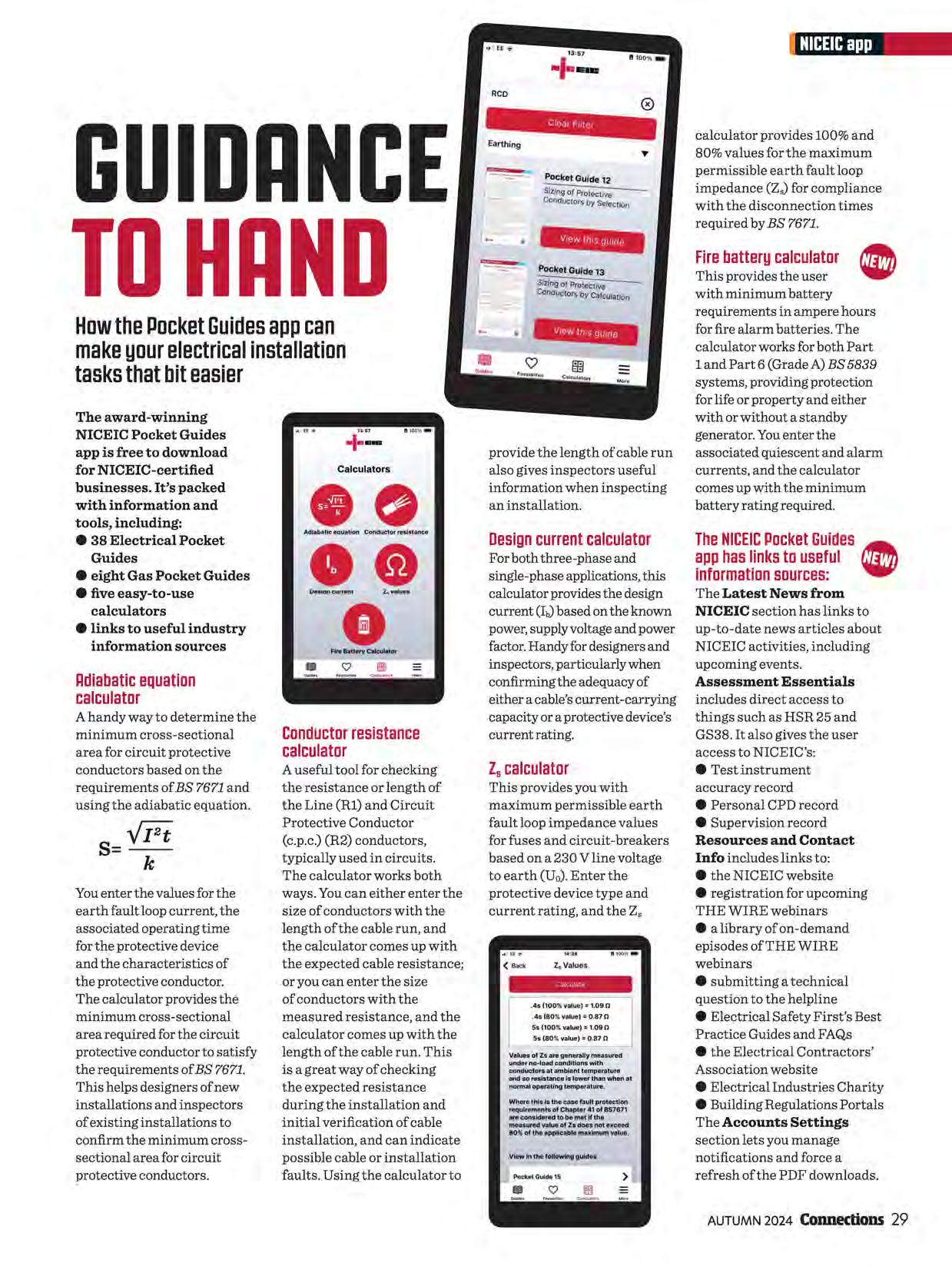
You enter the values for the earth fault loop current, the associated operating time for the protective device and the characteristics of the protective conductor. The calculator provides the minimum cross-sectional area required for the circuit protective conductor to satisfy the requirements of BS 7671. This helps designers of new installations and inspectors of existing installations to confirm the minimum crosssectional area for circuit protective conductors.
A useful tool for checking the resistance or length of the Line (Rl) and Circuit Protective Conductor (c.p.c.) (R2) conductors, typically used in circuits. The calculator works both ways. You can either enter the size of conductors with the length of the cable run, and the calculator comes up with the expected cable resistance; or you can enter the size of conductors with the measured resistance, and the calculator comes up with the length of the cable run. This is a great way of checking the expected resistance during the installation and initial verification of cable installation, and can indicate possible cable or installation faults. Using the calculator to
calculator provides 100% and 80% values for the maximum permissible earth fault loop impedance (Z.) for compliance with the disconnection times required by BS 7671.
provide the length of cable run also gives inspectors useful information when inspecting an installation.
For both three-phase and single-phase applications, this calculator provides the design current (Ib)based on the known power, supply voltage and power factor. Handy for designers and inspectors, particularly when confirming the adequacy of either a cable's current-carrying capacity or a protective device's current rating.
This provides you with maximum permissible earth fault loop impedance values for fuses and circuit-breakers based on a 230 V line voltage to earth (U 0). Enter the protective device type and current rating, and the Z,
This provides the user with minimum battery requirements in ampere hours for fire alarm batteries. The calculator works for both Part 1 and Part 6 (Grade A) BS 5839 systems, providing protection for life or property and either with or without a standby generator. You enter the associated quiescent and alarm currents, and the calculator comes up with the minimum battery rating required.
TheNICEICPocketGuides • apphaslinkstouseful informationsources:
The Latest News from NICEIC section has links to up-to-date news articles about NICEIC activities, including upcoming events.
Assessment Essentials includes direct access to things such as HSR 25 and GS38. It also gives the user access to NICEIC's:
• Test instrument accuracy record
• Personal CPD record
• Supervision record Resources and Contact Info includes links to: e the NICEIC website
• registration for upcoming THE WIRE webinars
• a library ofon-demand episodes of THE WIRE webinars
• submitting a technical question to the helpline
• Electrical Safety First's Best Practice Guides and FAQs
• the Electrical Contractors' Association website
• Electrical Industries Charity
e Building Regulations Portals
The Accounts Settings section lets you manage notifications and force a refresh of the PDF downloads.
With the start of the college year, thousands of new apprentices are taking their first steps on the ladder to becoming fully-fledged electricians.
If the electrical sector -and indeed the wider construction industry -is to get anywhere close to addressing the UK's predicted shortfall of qualified electricians and skilled tradespeople, then the recruitment of new starters is pivotal.

The industry needs to attract more than 100,000 additional electricians over the next eight years, according to the UK Trade Skills Index.
The electrical sector is awash with bosses and senior management whose own apprenticeship days are still a reasonably clear memory.
One of those is Andy Wood, Director of Rugby-based Hertz Electrical Contractors. He's clear how the decision

has benefited his life, and is keen to help as many others into the sector as he can.
"When I started out, I wanted to get away from the more formal educational route of A Levels and university," he says. "I thought work in the construction industry looked like fun and I managed to get onto an electrical apprenticeship. It worked for me and now I'm in the position where I can help others who struggle in a traditional educational setting."
With eight apprentices at various stages of their training regime at Hertz Electrical Contractors, Wood is certainly putting his money where his mouth is. (He gets £2,000 for each apprentice from Warwickshire County Council's Future Apprenticeships: Salary Support Programme via Warwickshire Skills Hub.)
"We try to take on two or three new starters every year," he explains. "We do get some that decide it's not for them but that's something we try to address before we offer any apprenticeship in the first place."
Those joining the sector will have a wider range of subjects and applications with which to familiarise themselves than in previous years. As the demand for solar PV, renewable power and electric vehicle charging infrastructure soars, apprentices must show their capability to adapt to these new challenges -without diminishing their thorough understanding of the more 'traditional' installation.
"For all apprentices to become fully qualified electricians they need to have a thorough understanding and experience across a broad range of work they will be expected to carry out," Wood says. "Renewables is becoming a more important part of the armoury for electricians but it's still based on the fundamentals of electrical installation we all learnt in our early career."
And while Hertz Electrical is generally keenest to take on postGCSE stage apprentices straight from school, there is another opportunity for firms
to have their pick of those who've decided university isn't for them.
The alternative route is T Levels (see Connections, Summer 2024, page 27). One place offering them is Leicester College, whose T Levels include Building Services Engineering with a specialism in Electrical Installation. Leicester College T-Level lecturer Derek Watters explains that "they're for those who are perhaps more academically capable. Students
"Theindustryneedsto attractmorethan 100,000additional electriciansoverthenext eightyears,according to theUKTradeSkillsIndex"
require a minimum standard at GCSE in Maths, English, Science and one other subject before we accept them onto our T Level course. But once they're on there we find that the students enjoy the mixture of classroom and practical learning they offer," he says.
As part of the course, all T Level students require an element of on-site experience through a work placement. This gives businesses an opportunity to assess potential apprentices before they take them on formally.
"It's a 'try before you buy' approachfor both parties," explains Watters, adding that "for larger organisations they really can offer a pipeline for talent".
As a relatively new qualification, T Levels may not yet be fully appreciated by the industry, but that's slowly changing, says Watters.
"Momentum behind them is building. We have 60 students in each year group, so T Levels are being recognised as valuable by students as either a way into industry or a pathway to university. We need to help employers -and indeed parents -gain a greater understanding of their value too," he adds.
In a sector that is forecast to be chronically short of fully qualified tradespeople within the next decade, gaining that understanding -and quicklycould be vital to its overall health.
First-year , apprentice ' AaronHillwas drawntathe sectorbythe challenges andthe variouscareeropportunities Itoffers,andapproachedthe teamatHertzElectrlcalabouta passlbleapprenticeship.
"IknewIdidn'twanta deskjab,"hesays."Iliketa bepractical.Theelectrical industryreallyappealed tame.Itseemsthemast challengingofthetradesand withnewtechnologiessuch asautomation,PYandEV becomingmarecommonplace, itcanofferadiversecareer.Sa farI'mreallyenjoyingit.Ilave hawmuchthereistalearn." WillRedgate isfurther dawnhis careerpath. HejoinedHertz Electricalas anapprentice sevenyearsago.He'ssince becameafullyqualified electricianandnowhelps developthenewrecruits.
"Theformaleducational settingofauniversitywouldn't havesuitedme,"hesays."I'm veryhappyIchasethiscareer andtheapprenticeshiproute. Ireallyenjoytheflexibility it offers.Natwodaysarethe same.We'recurrentlyhelping alocalbusinessimprovetheir energyefficiencythrough LEDlighting,PYandvoltage optimisation.NowI'mfully qualifiedImanageateamof electriciansandapprentices."

Our Weatherproof Range ensures safe, reliable outdoor electrical
access. Designed for high dust and water exposure, it boasts IP55 (Flush) & IP66 (Surface) ratings.
For added security, these padlockable products are available in
Flush and Surface Mount options. Manufactured in-house, Contactum
Options guarantees durability, exceptional service, and top quality.
Switch to Contactum's Weatherproof Range for protected outdoor
living, available across the UK.
Contact our Customer Services team for a stockist near you:
+442082087419ISales@contactum.co.uk
t's not often I need technical advice, but when I've come across a particularly unusual situation, I've run it past the NICEIC technical team," says Kelly Vincent, owner of Kelly Electrics, a small, all-female business serving domestic and commercial customers in London and Surrey.
She recalls one example: "I was designing garden lighting for two separate properties, each with an individual supply, but sharing a garden. I wanted to be certain of my understanding of how the earthing for the garden lighting would need to be installed to meet regulations and be safe for both households." As always, she says, the technical helpline's response was "quick and valuable".
It's well known that as an NICEICcertified business you have access to much more than the right to display
the NICEIC brand on your vehicle. The fact that your company has invested in becoming certified shows customers you are confident and proud to showcase any of your work. And our services and resources are available to your business every working day. These include the NICEIC technical helpline, where our experts can help you solve practical or theoretical problems, our NICEIC Pocket Guide app, which includes 37+ technical guides and calculators, live and on demand, THE WIRE webinars (recent topics have included leadership essentials and EICR coding), and live technical Q&As across NICEIC social media channels -see page 36 for full details.
Your NICEIC fees are also invested in the future of the electrotechnical industry, not just through NICEIC's work, but also through its work with the Electrical Contractors' Association (ECA) and Electrical Safety First
(ESF). They collaborate, alongside other industry organisations and the wider building services and construction sector, to improve standards and support businesses such as yours. The ECA and ESF are also co-owners of Certsure LLP, which operates NICEIC.
At the heart of our combined effort, says
NICEIC Technical Director
Paul Collins, is a shared "technical integrity goal", achieved through supporting and enhancing

(see 'NICEIC has got your back', right). For example, all three are members of the Wiring Regulations committee, JPEL/64, the BSijoint committee that develops the BS7671 standard.
The ECA is a trade association for electrotechnical contractors, installers and engineers working in England, Wales and Northern Ireland. Founded in 1901, it's the oldest of the three.
"As well as representing its members, the ECA serves the wider industry and the general public, in terms of safety and quality ofinstallation," says ECA Technical Director Mike Smith. It also works with partners including Build
UK and the Construction Leadership Council, to address issues such as slow payments to the competence of businesses.
These organisations also represent the industry in discussions with standards bodies and policymakers. They do this through membership of working and steering groups and committees, helping to guide the development of technical standards and regulatory requirements
contractors. It's campaigning for new legislation to improve payment practices and end abuse of cash retentions that leave small businesses bearing disproportionate financial risks. The ECA is calling for transparent payment systems to enable faster, fairer payments, and reform of the retentions system.
The ECA campaigns with the union Unite for fair pay and working conditions. The two are joint owners of the Joint Industry Board, which aims to improve training, competence and employment conditions to help businesses attract and retain good employees.
"It'snotoftenIneedtechnical advice,butwhenI'vecomeacross aparticularlyunusualsituation,I've runitasttheNICEICtechnicalteam"
The EC A's work with NICEIC and ESF is crucial. "NICEIC measures what a lot of our members and the wider industry are doing on site," says Smith.
rTheECA also draws on research and data gathered byESFon safety issues.
For its part, registered charity ESF works with the industry and policymakers to reduce deaths and injuries caused by electrical accidents.
ESF's key messages include discouraging consumers from attempting electrical work themselves; and encouraging electrical contractors and consumers to buy and use safe products from reputable suppliers. Its awareness campaigns include information and resources for parents and schools, to convey safety messages on topical issues.
In addition to its work on the JPEL/64 committee, ESF hosts the Wiring Regulations Advisory Group (WRAG), a discussion forum that addresses questions linked to application of the BS 7671 standard. Recently the WRAG worked on BS 7671 Amendment 3:2024: Requirements for Electrical Installations, which introduced new requirements for use of bidirectional and unidirectional protective devices (see Need to Know, page 39).
This has important implications for the safe operation of generating equipment, such as circuits connecting solar PV inverters, battery electric storage systems to consumer units or distribution boards. The WRAG has published a Q&A on allocation of classification codes for unidirectional devices in existing installations.
The Electrotechnical Skills Partnership (TESP): The not-for-profit organisation promotes careers in the electrotechnical industry, and higher standards of work. Its Electrician Plus initiative highlights electricians installing low-carbon technologies, and kitemarks qualifications including NICE IC training.
British Standards Institution (BSI): NICEIC supports BSI and IET (see below) on the development of the BS 7671:2018 Wiring Regulations (a joint standard). NICEIC also works with BSI on BS 5839 (fire detection and alarm systems in buildings), BS 5266 (emergency lighting), and PAS 2030 (retrofitting energy efficiency measures in existing homes).
The Institution of Engineering and Technology (IET) shares the role ofupdating BS 7671 with BSI.
MCS sets standards for lowcarbon energy technology products and installations. NICE IC contributes to MCS installer standards; and operates the NICEIC MCS Approved Contractor Scheme.
The Office for Zero Emission Vehicles (OZEV) works across government to support the transition to zero-emission road vehicles. NICEIC has worked with OZEV auditing competence of electric vehicle charging point installers.
E SF produces Best Practice Guides, covering topics such as electrical safety in private rented accommodation, and Electrical Installation Condition Reports (EICR). It also hosts an EICR Improvement Working Group, and an Electrical Installation Safety Forum.
All three organisations have contributed to the development of England's new regulatory regime for building safety. Alongside other construction sector and consumer organisations, they campaigned for the creation of a new regime, with their efforts helping lead to the passage through Parliament of the Building Safety Act, which received Royal Assent in 2022. Their work also helped inform the creation of the Building Safety Regulator (BSR). NICEIC is a member of the Competent Persons Forum, which works under the BSR to develop competence and compliance standards, and contributed to the most recent updates of the Mandatory Technical Competencies, due to be published soon. It's also a member of the Electrotechnical Assessment Specification (EAS) management committee, contributing to updates for the EAS, which specifies minimum requirements for a certified business seeking a competence certification for electrical work.
The ECA has made recommendations for competence requirements for installers and has helped to create professional development programmes
on fire safety knowledge. It has also supported the development of the Common Assessment Standard, with Build UK and other industry bodies, which can be used by contractors as a pre-qualification for bidding for public sector and some commercial project work and now includes a section on building safety.
ESF chairs a group on equipment maintenance and repair, on behalf of the Construction Leadership Council. "We're leading that group to make sure equipment is properly serviced and repaired, and doesn't impact on safety," says ESF Technical Director Martyn Allen. "With sensible enforcement, we should be in a much better place."
"It's an exciting time," says Smith. "We've seen more collaboration, not just between NICEIC, ESF and the ECA, but also with other industry bodies, coming together, recognising the need to ensure there is competence from an individual and organisational perspective. We're all pulling in the right direction."
Collins agrees. The work these organisations are doing together -funded in part by the fees every NICEIC-certified business pays -will ensure that the industry's workforce is "competent, supervised properly and doing the work correctly", he says.
So, ultimately, the contributions of every NICEIC-certified business are helping to ensure the safety of your colleagues and customers today; and to safeguard the future of your business and your industry.
"We'releading[theeguipment

THEWIREisourin-depth,CPD-accreditedwebinarseries thatisexclusivetoNICEIC-certifiedbusinesses.
It delivers everything you need to enhance your knowledge, stay updated on changes to legislation and regulations, and give useful information to help you run your business. You can quiz our experts and engage with peers in the industry, all from the comfort of your own home or workplace.
Doyouhaveatechnicalquestionorneedabitofadvice?
Don't miss our Technical Q&A live stream on Facebook and YouTube the first working Monday of each month at 8pm* and ask your question to NICEIC'stechnical experts. Get notified when we go live by liking our page on Facebook.com/NICEIC or subscribe to our channel at YouTube.com/niceic1
Missedthelivebroadcast?
No problem, access over 30 hours of CPD accredited content in our on-demand library.
NICEICInsuranceServicesisdesignedspeciallyfortheelectricaltrade, withyourbespokepolicycreatedjustforyourbusiness

by NICEICInsurance Services protects your livelihood.
lpQLICv7 InAu~st, t~elnstitution l..!: .!.JofEngmeermg and Technology (IET) and the British Standards Institution (BSI) published a Draft for Public Comment (DPC) on proposed changes (Amendment 4:2026) to the current BS 7671:2018+Amendment 3:2024 JET Wiring Regulations.
"We strongly encourage electrical professionals to respond to this DPC," says NICEIC Technical Director Paul Collins. "Your insights are crucial in helping shape these regulations."
Amendment 4:2026 will incorporate changes to harmonise standards at a European level. The UK must incorporate the technical intent of these changes as part of the BS 7671 revision programme.
IET Head of Technical Regulations Mark Coles says: "It is intended that this amendment will include requirements for stationary
secondary batteries, low-voltage generating sets, power over ethernet, energy efficiency, functional earthing and functional-equipotentialbonding for information and communication technology equipment and systems."
The need for further clarity on unidirectional and bidirectional protective devices became evident through enquiries to our technical helpline. This feedback informed our recommendations in the DPC.
Amendment 4:2026 is expected to be published in 2026. Until then, electrical businesses need to have a copy of Amendment 2:2022 -the 'brown book', the Corrigendum (May 2023) andAmendment3:2024. The latter two documents are available as free PDF downloads. To comment by 3 November, register on the BSI Standards Development portal.

TohelpyounavigatetheDPCproposals, we'vecreatedasuiteofresources, includingwebinars,videosanda dedicatedblog.Allareavailable at niceic.com/amendment-four
Apprentices and their training providers will soon have new support: the Apprentice Channel ofExcellence (ACE).
It will provide digital learning resources to support the study of Level 2 and 3 Electrical Installation.
The new venture is a collaboration between Electrical Safety First and LearningLounge, an award-winning provider of digital learning content to further education colleges and the wider electrotechnical training sector.
ACE will offer videos on science and theory, health and safety, practical skills, plus benchmarking quizzes, assessments and expert advice.
The eight highest-scoring SkillELECTRIC competitors from the national qualifying heats are prepping for the UK finals.
The finalists, pictured from top left, are: Charlie Moore of Bramham Electrical and College ofWest Anglia; Fabien Maciejewski, a completed T Level Learner at Leicester College; Ewan Thomas of JGM Services Electricians and SECTT; John Ross Campbell at A Campbell Electrical Services and SECTT; Jonathan Gough of MD Electrics and Southern Regional College; Kalum Low at MS Electrical and Renewables and SECTT; Milly Smith at CS

McKerlie Electrical Services and SECTT; and Dudley College's Richard Westwood.
SkillELECTRIC, the annual search for the UK's best student electrician, is organised by industry charity National Electrotechnical Training and sponsored by NICEIC. As part of our sponsorship, we're running a free online EV fundamentals course for the finalists. The final is held at Oldham College from 18 November. Top performers could be in with a chance to represent the UK in the Electrical Installation competition at WorldSkills 2026 in Shanghai, China.
Electrical Safety First's conference on 21 November in Westminster is titled Time for Change, and will explore the key trends impacting the electrical product industry.
The event will be attended by representatives from more than 200 government departments, manufacturers, retailers, importers, lawyers, fire and rescue services, and test houses.
Speakers will explore issues, and share insights on electrical product innovation to help the UK transition to net zero. See electricalsafety first.org.uk/ conference
Could one of your jobs be crowned NICE IC installation of the month?
Our new competition highlights the best work of NICEIC-certified businesses. Send us images of a recent electrical installation you're really proud of, and tell us why it deserves to win. We'll select a winner, and will feature it on our Instagram page. And you'll win a training course of your choice (subject to entry requirements). You'll be judged on the technical difficulty of the installation, the quality of the pictures and the written context you provide. To get involved, go to our Instagram page and like the launch post of the competition. Each NICEIC-certified business is limited to one entry per month. Good luck!
ThenewseriesofTHEWIRE is nowunder wayandincludesthefollowingepisodes:
• TheDraftforPublicConsultation(DPCJ ofAmendment4:i!Oi!6to BS7671:801Bwhatit isandwhatyouneedto know
• UncovertheprocessbehindtheUK's keyelectricalstandard:BS7671
• EssentialpreparationforyourNICEIC MCSassessment
• EssentialupdateonElectricalEnergy StorageSystems(EESSJ e vourNICEICassessment:common mistakesandhowto avoidthem Signupfortheliveeventordownload on-demand at niceic.com/thewire
As an NICEIC-certified business, you get money off thousands of products through B&Q/TradePoint for you and your staff.
NICEIC's partnership with TradePoint gives you a 10% discount on almost everything they stock. Visit the NICEIC Customer Portal to submit a request for a membership card direct to TradePoint.
Fromnowon,you'llgetjusttwomonthlynewslettersfromus.TheCircuit willdeliveralltheessentialinformationbusinessesneedaboutNICEIC certification.AndNICEICInsightswillkeepyouupto dateonthingslike trainingopportunitiesandindustrynews.
Your last chance to meet up with our experts at ELEXSHOW this year is 7-8 November at Sandown Park in Surrey. NICEIC's stand will showcase our new EICR Station, which highlights common issues found when undertaking an electrical installation conditioning report (EICR). This will sit alongside the demonstration rig, showing technologies such as solar PV. And our experts will be giving technical presentations.
We'll be back at ELEX next year too. Visit us at the Bolton Arena on 6-7 March, and at Alexandra Palace, London, on 27-28 March.
For the first time, more than 40% of global electricity came from zero-carbon sources in 2023. According to two reports from BloombergNEF, hydropower accounted for 14.7%,wind and solar combined for nearly 14% (a new record), and nuclear 9.4%.
The reports claim that wind and solar represented nearly 91% of net new power capacity in 2023 -up from 83% the year before -while fossil fuels, including coal and gas, represented just 6% of net new build, which is the lowest level ever.

Ourtechnicalengineersansweryourquestionson safetystandards,periodicinspectionsandreporting
What are the requirements/ recommendations for the interval between periodic inspections in houses in multiple occupation (HMOs)?
In England, the requirements and recommendations given in the Electrical Safety Standards in the Private Rented Sector (England) Regulations 2020 are applicable to HM Os.
In Scotland, the Licensing of Houses in Multiple Occupation: Statutory Guidance for Scottish Local Authorities states that:
• Appropriate certificates; that is for the fixed installation, an Electrical Installation Condition Report (EICR) or formerly a Periodic Inspection Report (PIR), be available to show that the electrical system for the property is safe (paragraph 4.10.7).
• The EICR has been renewed at least every five years, or earlier if this was directed in the EICR (paragraph 4.10.8). For more, visit bit.ly/HMOs-Scotland

Following the publication of the Electrical Safety Standards in the Private Rented Sector (England) Regulations 2020, which came into force on 1 June 2020, what are the requirements for the frequency of periodic verification of premises?
Part 2 of these regulations deals with the duties of private landlords in relation to electrical installations. Regulation 3, paragraph (1) states that a private landlord who grants or intends to grant a specified tenancy must ensure that:
(a) the relevant electrical safety standards given in BS7671:2018 are met during any period when the residential premises are occupied under a specified tenancy; and (b) the electrical installation in the
residential premises is inspected and tested at regular intervals by a qualified person; and (c) the inspection and testing is carried out before a specified tenancy commences.
Regulation 3, paragraph (2) states that for the purposes of sub-paragraph (l)(b) "at regular intervals" means:
(a) no more than five years after the initial certification of the electrical installation or the issue of an Electrical Installation Condition Report where the overall assessment of the installation, in terms of electrical safety and suitability for continued use, is stated as being satisfactory; or (b) where the most recent report under sub-paragraph (3)(a) requires such inspection and testing to be at intervals ofless than five years, at the intervals specified in that report.
Following on from Q2, what are the requirements regarding the documentation which must be issued on completion of the inspection and testing?
Regulation 3, paragraph (3) requires that following the inspection and testing required under subparagraphs (l)(b) and (c) a private landlord must:
(a) obtain a report (an EICR) from the person conducting that inspection and testing, which gives:
• the results of the inspection and testing, and
• the date by the next inspection and testing should be carried out;
(b) supply a copy of that report to each existing tenant of the residential premises within 28 days of the inspection and testing;
(c) supply a copy of that report to the local housing authority within seven days of receiving a request in writing for it from that authority;
(d) retain a copy of that report until the next inspection and testing is due and supply a copy to the person carrying out the next periodic inspection and testing; and
(e) supply a copy of the most recent report to:
(i) any new tenant of the specified tenancy to which the report relates before that tenant occupies those premises; and
(ii) any prospective tenant within 28 days of receiving a request in writing for it from that prospective tenant.
Following on from Q8, what action must be taken when the overall outcome of the report is unsatisfactory as a result of the.findings obtained during the periodic inspection and testing?
Regulation 3, paragraph (4) requires that where a report under sub-paragraph (3)(a) indicates that the installation does not meet the relevant electrical safety standards given in BS 7671: 2018 and the report requires the private landlord to undertake further investigative or remedial work, the private landlord must ensure that such investigative or remedial work is carried out by a qualified person within:
(a) 28 days; or
(b) where the person who compiled the report has specified a timescale, the period specified in the report ifless than 28 days, starting from the date of the inspection and testing.
Regulation 3 paragraph (5) further requires that where paragraph (4) applies, a private landlord must:
(a) obtain written confirmation from a qualified person that the further investigative or remedial work called for in the report has been carried out and that:
(i) the relevant electrical safety standards given in BS 7671: 2018 are now met; or
(ii) further investigative or remedial work is required;
(b) supply written confirmation, together with a copy of the original report which required the further investigative or remedial work to each existing tenant of the residential premises within 28 days of completion of the further investigative or remedial work; and
(c) supply written confirmation, together with a copy of the original report which required the further investigative or remedial work to the local housing authority within 28 days of completion of the further investigative or remedial work.
Regulation 3 paragraph (6) states that where further investigative work is carried out in accordance with paragraph (4) and the outcome offurther investigation is that further investigative or remedial work is required, the private landlord must repeat the steps in paragraphs (4) and (5) in respect of that further investigative or remedial work.
The draft regulations can be downloaded from bit.ly/PRS-regs

Whether the job is big or small, from changing a consumer unit to rewiring an entire commercial facility, from those jobs you can do with your eyes closed to a never-before-attempted solar or EV install, the most essential kit in your armoury is a copy of the IET Wiring Regulations -the 'brown book'.
No matter what the job is, the Regs sets the standard every time so, have you got a copy in your toolkit?

Objective:This article explores some of the considerations involved when specifying and installing a DC switch-disconnector, also known as a DC isolating switch, as a means of isolation between the solar photovoltaic array and the inverter.
Where a Solar PV inverter is installed, a means of isolation from both the AC and DC supplies is required (712.537.2.101). This article will focus on DC isolation, which is achieved through a switchdisconnector on the DC side of the inverter (Figl).
A DC switch-disconnector faces greater challenges than its AC counterpart. With an AC system operating at 50 Hz, the voltage crosses zero twice per cycle, occurring every 10 milliseconds (Fig 2(a)), which helps suppress electrical arcs. However, DC voltage is constant and lacks this zero-point crossing (Fig 2(b)), making arc extinction more difficult.
In AC systems, the natural zero voltage points in the cycle help extinguish electrical arcs during switching. Conversely, in DC systems, the steadystate voltage means that when contacts are separated, the voltage remains, creating a strong magnetic field within the air gap. This increases the likelihood of air ionisation between the switching contacts allowing current to bridge the air gap creating an arc. To combat this, DC switches may incorporate a spring-assisted mechanism to enable a fast make-and-break action. Some DC switches also employ multiple contacts to extend the arc path and aid in arc extinction.
A switch-disconnector is required for isolation of the inverter, but what exactly is a switch-disconnector?
Part 2 of BS 7671 defines a switch disconnector as: '~ switch which, in the open position, satisfies the isolating
Fig 2 AC & DC voltage magnitude as a function of time (a)
(b) DIRECTCURRENT
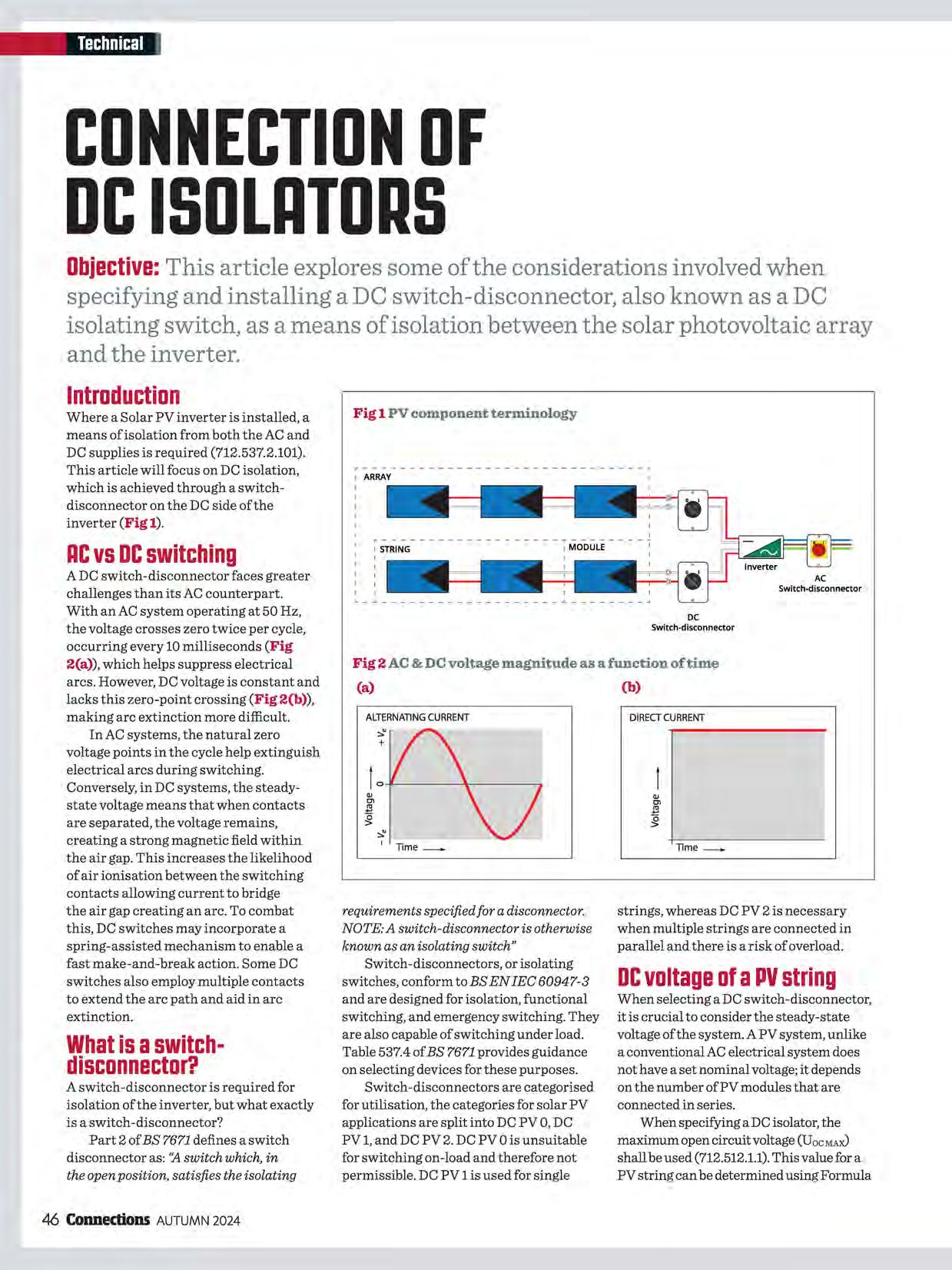
requirements specified for a disconnector. NOTE: A switch-disconnector is otherwise known as an isolating switch"
Switch-disconnectors, or isolating switches, conform to BS EN IEC 60947-3 and are designed for isolation, functional switching, and emergency switching. They are also capable of switching under load. Table 537.4 of BS 7671 provides guidance on selecting devices for these purposes.
Switch-disconnectors are categorised for utilisation, the categories for solar PV applications are split into DC PV 0, DC PV 1, and DC PV 2. DC PV 0 is unsuitable for switching on-load and therefore not permissible. DC PV 1 is used for single
strings, whereas DC PV 2 is necessary when multiple strings are connected in parallel and there is a risk of overload.
When selecting a DC switch-disconnector, it is crucial to consider the steady-state voltage of the system. A PV system, unlike a conventional AC electrical system does not have a set nominal voltage; it depends on the number of PV modules that are connected in series.
When specifying a DC isolator, the maximum open circuit voltage (UocMAlU shall be used (712.512.1.1).This value for a PV string can be determined using Formula
1.Another method for determining UocMAX is available, although this requires knowledge of the module temperature coefficient and minimum site temperature.
Formulal
UocMAx=No.of modules x UocsTcx 1.2
Where:
UocMAxis the maximum string open circuit voltage.
No. of modules is the total number of modules on the string.
U ocsTcis the open circuit voltage of the module under standard test conditions as declared by the manufacturer.
1.2 is a multiplier to take account of the voltage rise under a temperature lower than that of standard test conditions.
Knowing the value of DC current that the disconnector will have to interrupt is critical when selecting a switchdisconnector, as higher currents generate more heat in the arc. The magnitude of this current is proportional to the number of PV modules or strings connected in parallel. When selecting equipment for PV arrays, including DC isolators, the short-circuit maximum current (lsc MAJU shall be used (712.512.1.2).
Formula 2 can be used to calculate this value.
Formula2
lscMAX=No.of strings x lscsTcx 1.25
Where:
lsc MAX is the array maximum short-circuit current
No. of strings is the total number of strings in parallel
Isc sTcis the short-circuit current of the module under standard test conditions as declared by the manufacturer
1.25 is a multiplier to take account of the higher irradiance than that of standard test conditions
In order to determine the maximum current and voltage for a DC switchdisconnector, the manufacturer's details of the PV module are required. An example of this is shown in Fig 5.
Example
Using the example data given in Fig 5, determine the maximum voltage
and current for selecting a switchdisconnector for a single string containing 20 of the PV modules wired in a series configuration, with no other strings connected in parallel. Formulas 3 and 4 can be used to calculate the maximum voltage and current, respectively.
Formula3
UocMAX=No.of modules x UocsTcx 1.2
UocMAx = 20 x 39V x 1.2
UocMAX = 936V
HypotheticalPVPower
All data at standard test conditions
lrradiance: 1000 W/m2
Air mass: 1.5
Temperature: 25 °c
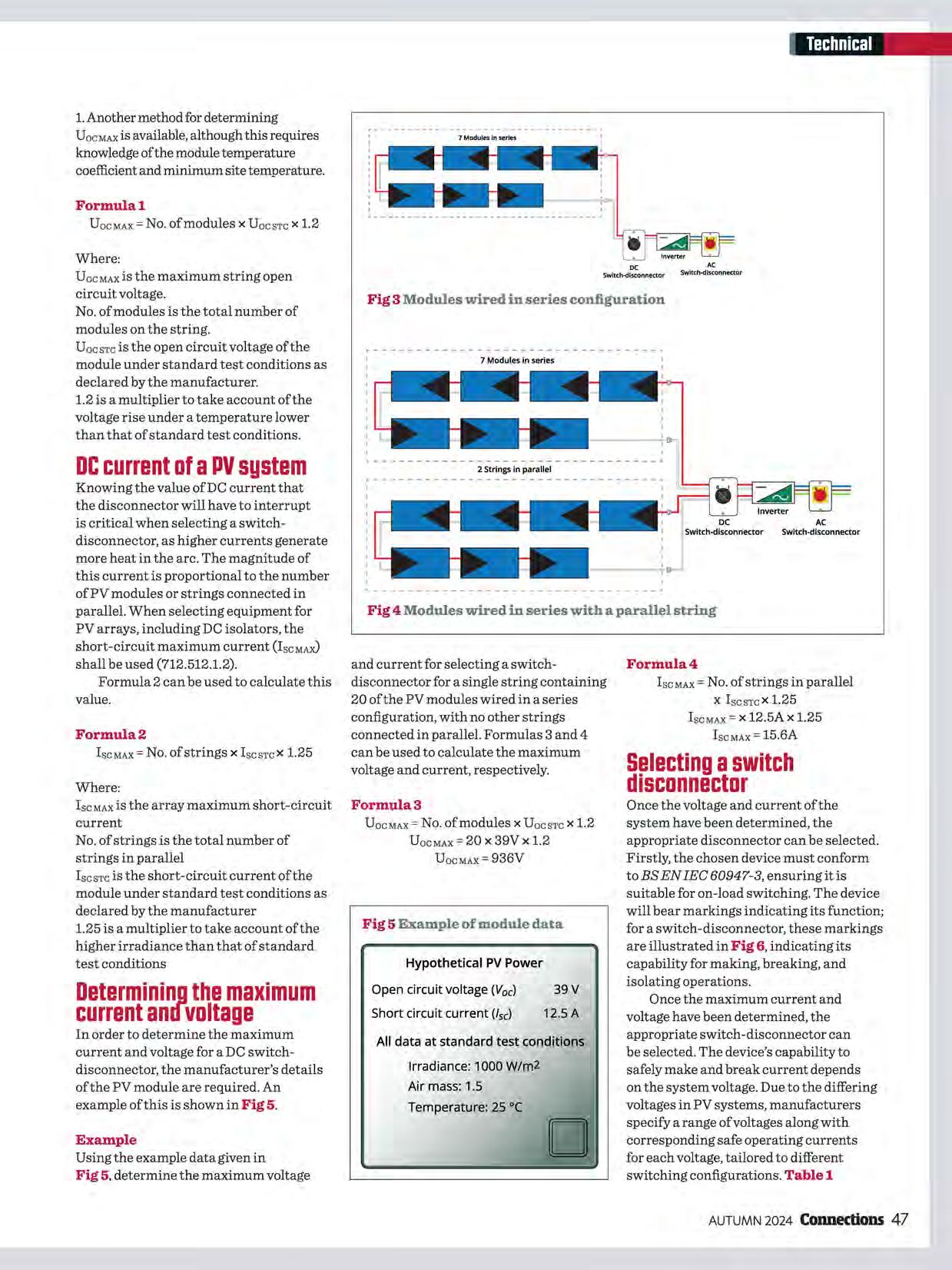
Formula4
lsc MAX = No. of strings in parallel X lscsTcX1.25
lsc MAX= x 12.5A x 1.25 lscMAx= 15.6A
Once the voltage and current of the system have been determined, the appropriate disconnector can be selected. Firstly, the chosen device must conform to BS EN IEC 60947-3, ensuring it is suitable for on-load switching. The device will bear markings indicating its function; for a switch-disconnector, these markings are illustrated in Fig 6, indicating its capability for making, breaking, and isolating operations.
Once the maximum current and voltage have been determined, the appropriate switch-disconnector can be selected. The device's capability to safely make and break current depends on the system voltage. Due to the differing voltages in PV systems, manufacturers specify a range of voltages along with corresponding safe operating currents for each voltage, tailored to different switching configurations. Table 1

represents hypothetical manufacturer's data for a DC disconnector.
Using the voltage and current values determined previously, the appropriate wiring configuration can be selected from Table 1.
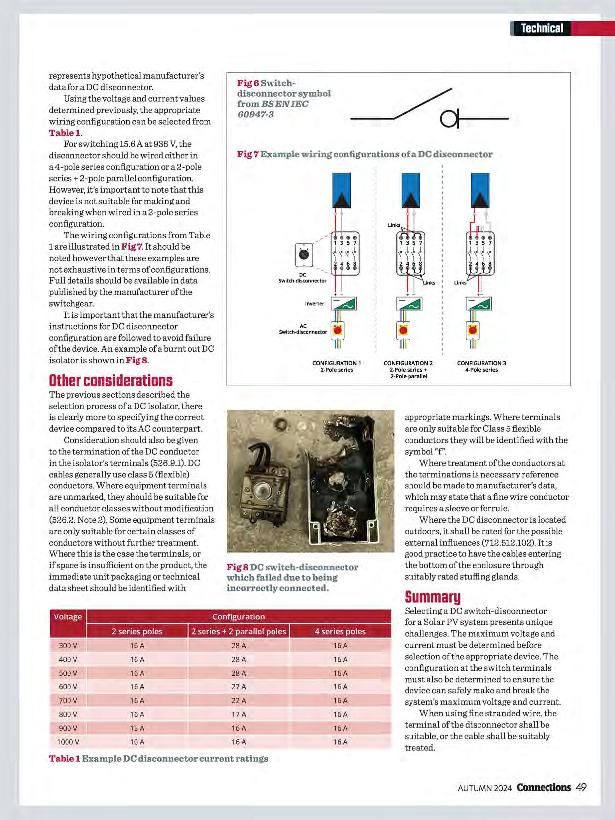
Fig 6 Switchdisconnector symbol from BS EN IEC 60947-3
For switching 15.6 A at 936 V,the disconnector should be wired either in Fig 7 Example wiring configurations of a DC disconnector a 4-pole series configuration or a 2-pole series+ 2-pole parallel configuration. However, it's important to note that this device is not suitable for making and breaking when wired in a 2-pole series configuration.
The wiring configurations from Table 1 are illustrated in Fig 7. It should be noted however that these examples are not exhaustive in terms of configurations. Full details should be available in data published by the manufacturer of the switchgear.
It is important that the manufacturer's instructions for DC disconnector configuration are followed to avoid failure of the device. An example of a burnt out DC isolator is shown in Fig 8.
The previous sections described the selection process of a DC isolator, there is clearly more to specifying the correct device compared to its AC counterpart. Consideration should also be given to the termination of the DC conductor in the isolator's terminals (526.9.1). DC cables generally use class 5 (flexible) conductors. Where equipment terminals are unmarked, they should be suitable for all conductor classes without modification (526.2. Note 2). Some equipment terminals are only suitable for certain classes of conductors without further treatment. Where this is the case the terminals, or if space is insufficient on the product, the immediate unit packaging or technical data sheet should be identified with
CONFIGURATION2 2-Poleseries+ 2-Poleparallel
CONFIGURATION 3 4-Poleseries
appropriate markings. Where terminals are only suitable for Class 5 flexible conductors they will be identified with the symbol"f'.
Where treatment of the conductors at the terminations is necessary reference should be made to manufacturer's data, which may state that a fine wire conductor requires a sleeve or ferrule.
Where the DC disconnector is located outdoors, it shall be rated for the possible external influences (712.512.102). It is good practice to have the cables entering the bottom of the enclosure through suitably rated stuffing glands.
Selecting a DC switch-disconnector for a Solar PV system presents unique challenges. The maximum voltage and current must be determined before selection of the appropriate device. The configuration at the switch terminals must also be determined to ensure the device can safely make and break the system's maximum voltage and current.
When using fine stranded wire, the terminal of the disconnector shall be suitable, or the cable shall be suitably treated.
Table 1 Example DC disconnector current ratings

Objective: In some cases, it is necessary to know the maximum permitted earth fault loop impedance (Zs) for the protective device used. This is to confirm the requirements for automatic disconnection in the event of a fault as part of the protective measure Automatic Disconnection of Supply (ADS). This article explores how designers and inspectors can determine the maximum permitted Zs for both circuitbreakers and moulded case circuit-breakers (MCCBs).
Circuit-breakers and MCCBs, manufactured to BS EN 60898 and BS EN 60947-2 respectively, are commonly used to provide automatic disconnection in the event of a fault as part of the protective measure ADS. In such cases, it is the responsibility of the designer to ensure that the protective device will operate within the permitted time. This is generally verified where the measured Zs is less than or equal to the maximum Zs permitted for the device.
The maximum disconnection times for ADS are contained within Chapter 41 of BS 7671. Table 1 displays the disconnection times for a TN system with a voltage to earth (Uo) of230 V AC.
Where a protective device to BS EN 60898 or BS EN 61009-1 is used, it is common practice to refer to Table 41.3 of BS 7671 to determine the maximum permitted Zs. However, the following statement given in Appendix 3 of BS 7671 should also be considered:
"The maximum values of earth fault loop impedance to achieve the disconnection time vary with the different types of protective device and also between manufacturers. Wherever possible designers should use the manufacturer's specific data. Alternatively, the impedance values given in Tables 41.3 and 41.6 can be used for
Final circuits of rated current not exceeding 63 A that include one or more socket-outlets (411.3.2.2)
Distribution circuits and circuits not covered by 411.3.2.2 (411.3.2.3)
Table 1 Typical disconnection times for a TN system

BS EN 60898 circuit-breakers. These values are far more onerous and in some cases may be difficult to achieve without installing larger sized cpcs."
The designer therefore needs to understand how to determine the maximum Zs values from manufacturers' data for a specific protective device.
The values in Table 41.3 are obtained from the time/current characteristics curves given in Appendix 3. Formula 1 shows how this is determined.
Formula!
Where:
Cminis a correction factor to account for voltage variations. This is given as 0.95 in Appendix 3 of BS 7671.
U o is the nominal AC rms line voltage to Earth.
I. is the current causing operation of the device in a specified time. For a Type C circuit-breaker this is 5 x the nominal current rating of the device (In)
When not using the values given in Table 41.3, to obtain the value of Zs, knowledge ofI. is required. To find the value ofI. for a specific manufacturer's device, the relevant time/current graph
Fig 1 Time/current graph for an imaginary Type C thermal-magnetic device
is required. These can be obtained from the manufacturers' websites. Fig 1 represents a time/current curve for an imaginary Type C circuit-breaker. This graph differs slightly from that of Appendix 3, as this displays the operational tolerance of the device, and is also representative of multiple device ratings within the Type C range. This graph represents thermal-magnetic circuit-breakers, the vertical line represents the magnetic part of the device, whereas the curve represents the thermal part.
To determine the value of current causing operation of the protective device (I.), the following steps are carried out:
1. Identify the disconnection time: Determine the required disconnection time for the device from Chapter 41 of BS7671.
2. Draw horizontal line: From the y-axis (time axis) on the graph, draw a horizontal line across the graph corresponding to the required disconnection time, for example 0.4 seconds.
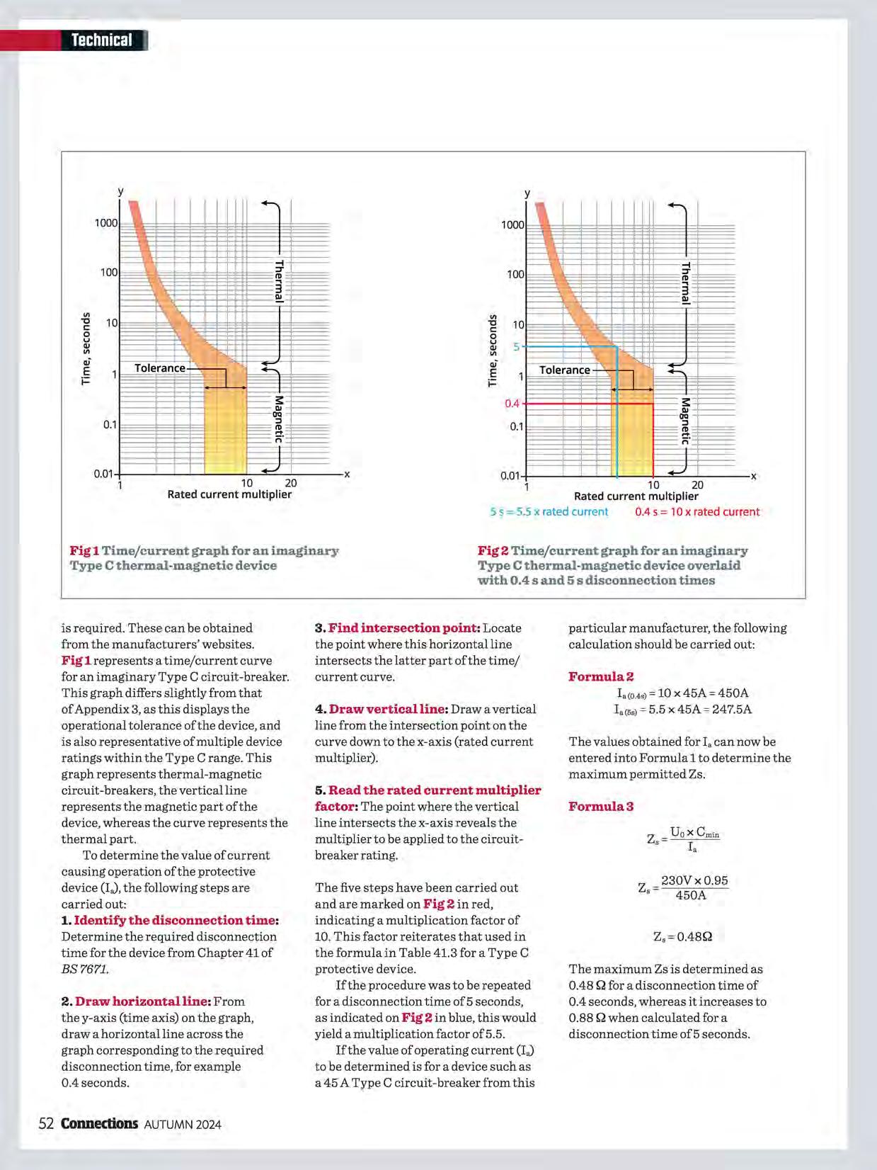
Fig 2 Time/current graph for an imaginary Type C thermal-magnetic device overlaid with 0.4 sand 5 s disconnection times
3. Find intersection point: Locate the point where this horizontal line intersects the latter part of the time/ current curve.
4. Draw vertical line: Draw a vertical line from the intersection point on the curve down to the x-axis (rated current multiplier).
5. Read the rated current multiplier factor: The point where the vertical line intersects the x-axis reveals the multiplier to be applied to the circuitbreaker rating.
The five steps have been carried out and are marked on Fig 2 in red, indicating a multiplication factor of 10. This factor reiterates that used in the formula in Table 41.3 for a Type C protective device.
If the procedure was to be repeated for a disconnection time of 5 seconds, as indicated on Fig 2 in blue, this would yield a multiplication factor of 5.5.
If the value of operating current (I.) to be determined is for a device such as a 45 A Type C circuit-breaker from this
particular manufacturer, the following calculation should be carried out:
Formula2
Ia(0.4s) = 10 X 45A = 450A Ia(5s) = 5.5 X 45A = 247.5A
The values obtained for I. can now be entered into Formula 1 to determine the maximum permitted Zs.
Formula3
z = 230V x 0.95 ' 450A
Z,=0.48Q
The maximum Zs is determined as 0.48 Q for a disconnection time of 0.4 seconds, whereas it increases to 0.88 Q when calculated for a disconnection time of 5 seconds.
While the previous examples given are based on circuit-breakers, the principle for obtaining I. for a thermal-magnetic MCCB remains the same. However, there may be other settings on the device that need to be considered.
Many MCCBs incorporate means to adjust the thermal and magnetic characteristics of the device.
The basic settings are listed below:
I,: adjusts the Long-time current thermal setting
I,d (or Im): adjusts Short-time magnetic setting
The I, adjustment is manufacturer dependent, although this can be a factor of the Invalue, such as 0.63 to 1.0. As an example, an MCCB with an In rating of 100 A with an I, setting of0.8 would give anI,of80A.
Similarly, the I,d setting can be somewhere around 1.5 to 10, which is a factor based on the In or I, setting of the device. As an example, using the Irvalue of0.8 and an I,d setting of 7, the I,dwould be 560 A (80 Ax 7 = 560 A). Fig 3 depicts these settings.
Once the values have been determined by the designer, the following steps will enable the maximum Zs value for the corresponding 0.4 sand 5 s disconnection times to be obtained.
For a 0.4 s disconnection time it is not necessary to consult the graph as I,d equals I •. However, prior knowledge of the device's tolerance is required.
For example, if the manufacturer states there is a 10 % tolerance on the device, this should be factored into the calculation as shown in Formula 4.
Note: the factor ofl.1 accounts for the 10% tolerance stated.
230x0.95 z, 560 xl.1
Z,=0.35Q
To obtain the operating current (I.) for a 5 s disconnection time, the graph would be referenced. Utilising Graph 2 as the imaginary MCCB time/current curve, the value ofia would be 440 A (5.5 x 80 A= 440 A). With the current I. obtained, the maximum permitted Zs can now be calculated as shown in Formula 5.
230x0.95 z, 440
Z,=0.49Q
This article is limited to thermalmagnetic devices, although MCCBs are sometimes equipped with an electronic trip. If electronic devices are used, manufacturers' information should be sought to obtain I. and
the corresponding maximum Zs for the devices.
Some manufacturers may provide software to aid determination of the values for their devices. This can be the most accurate and least timeconsuming method for determining the maximum Zs and is essential where electronic devices are used.
To ensure compliance with ADS, the maximum permitted Zs of the protective device needs to be obtained to ensure the measured value of Zs is within range. According to BS 7671, manufacturers' specific data should be utilised whenever possible.
Objective: In electrical engineering, graphs and charts serve as an essential tool for communication and data representation. The aim of this article is to look at graphs that specifically use log-log scales. Such graphs can offer a convenient way to analyse and visualise data in an easy and understandable format once their construction is understood. It is therefore important that electrical contractors are aware of how to read and interpret these graphs. This article will focus on those found in Appendix 3 of BS7671 and those issued by manufacturers to assist in the selection of overcurrent protective devices.
Log-log paper is a resource that makes use of the logarithmic scale where each incremental unit is arranged in a series of uneven bands grouped within repetitive cycles, and which signifies either a tenfold increase or decrease in a quantity. Logarithmic graph paper is a useful way ofrepresenting data that covers an extensive range ofvalues 1 For instance, it may prove difficult when needing to accurately display data ranging from, say, 0.01to1000 000 on the same scale. However, displaying such information may be achieved using a logarithmic scale that allows each cycle to represent a distinct range, as shown in Fig la).
Consider the log-log paper in Fig la, the horizontal axis starts at 1 within the first cycle which then increases in single lines unevenly spaced to a value of 10. Each subsequent line within the next cycle then represents an increase oflO up to a 100; then similarly, each further line represents an increase ofl00 and so on until 10,000 is reached.
Likewise, the vertical axis starts at 0.01 and progresses up to 10,000 in similar steps. However, representation of these values remains undefined until the axes are labelled.
The graph shown in Fig lb shows the characteristic curve of a 32 A fuse to BS 88-2 where the vertical axis shows time (s) and the horizontal axis shows prospective current (A).

To demonstrate how to interpret such a graph, let's assume a prospective fault current of 250 A has been calculated; the red dotted line intersects the fuse characteristic curve which indicates that the fuse takes approximately 0.4 s to operate.
There are two important observations about the time/ current characteristic curves given in Appendix 3 of BS 7671: i. The curves have been cropped at 0.1 s. For disconnection times less than 0.1 s, it becomes necessary to refer to manufacturers' data. ii. In relation to the curves associated with protective devices to BS EN 60898, the slowest operating times are shown.
Manufacturers' charts
Where fault conditions result in very short disconnection times ofless than 0.1 s, the characteristic curves detailed in Appendix 3 are no longer applicable. The designer will therefore need to consult manufacturers' data to determine the let-through energy (Ft). Such issues with short disconnection times are generally more of a concern on commercial and industrial installations rather than in a typical domestic installation.
The ability of a cable to withstand the energy during a fault and subsequent increase in temperature is dependent on its cross-sectional area (S),
resistivity, temperature coefficient, heat capacity of the conductor material, and the appropriate initial and final temperature (k).
The 'let-through' energy generated during the period of the fault is given by the formula:
Ft
Whereas the thermal 'withstand' formula for a cable is given by: k2s2
As such, it is important to remember that the value of k2S 2 for the cable is not less than the value oflet-through energy (Pt) quoted by the device manufacturer, i.e.
I2t < k2 S2 (434.5.2).
An example chart demonstrating the energy let-through against prospective short-circuit current is shown in Fig 2.
Based on the previous example and graph of Fig lb which considered a 32 A BS 88-2 fuse, what would happen when the fault current is increased to 3,000 A rather than 250 A?
From the characteristic curves given in Appendix 3 of BS 7671 it is evident that the disconnection time will be less than 0.1 sand, therefore, manufacturers' data will need to be assessed. Using the graph of Fig 2, with a fault current of 3,000 A, the let-through energy (Pt) is about 12,000A 2 s.
Providing the product of the k factor (Table 43.1 of BS7671) and the conductor cross-sectional area, both squared (k2SZ), is greater than 12,000, compliance with regulation 434.5.2 will be achieved.
Log-log graphs are a vital tool used in electrical engineering for analysing and visualising data across an extensive range of values. This article has explained the use oflog-log scales, particularly as used in Appendix 3 of BS7671.
Where fault conditions result in a very short disconnection time ofless than 0.1 s, manufacturers data charts should always be considered when selecting suitable overcurrent protective devices.
Footnote
1 Logarithmic graph paper can be either log-log, where both scales are logarithmic, or log-lin, where only one scale is logarithmic and the other is linear.
Prospectiveshort-circuitcurrent(A)
Fig 2 Example of a manufacturer's chart showing the let-through energy for BS 88-2fuses. (This chart is for illustration purposes only)
Objective: BS 7671 outlines several safety requirements for installations with harmonic currents. This article in particular focuses on the methods for sizing four-core and five-core cables carrying current having triplen harmonic content, and includes using a practical example.
An article in Connections, issue 229, explained harmonic currents and their origins. A second article in issue 230 introduced triplen harmonic currents in a three-phase circuit and highlighted the necessity ofincreasing cable conductor size to accommodate such types of harmonics.
When determining the required size of multi-core cables, Appendix 4 of BS 7671 provides tabulated values of current-carrying capacity based fundamentally on a balanced three-phase circuit with no harmonic content, and where the current and heating effect in the neutral conductor is zero. The current-carrying capacity of a four-core cable is therefore considered equivalent to that ofa three-core cable of the same construction and conductor size.
In contrast, a current will fl.owin the neutral conductor of an unbalanced three-phase circuit with no harmonic
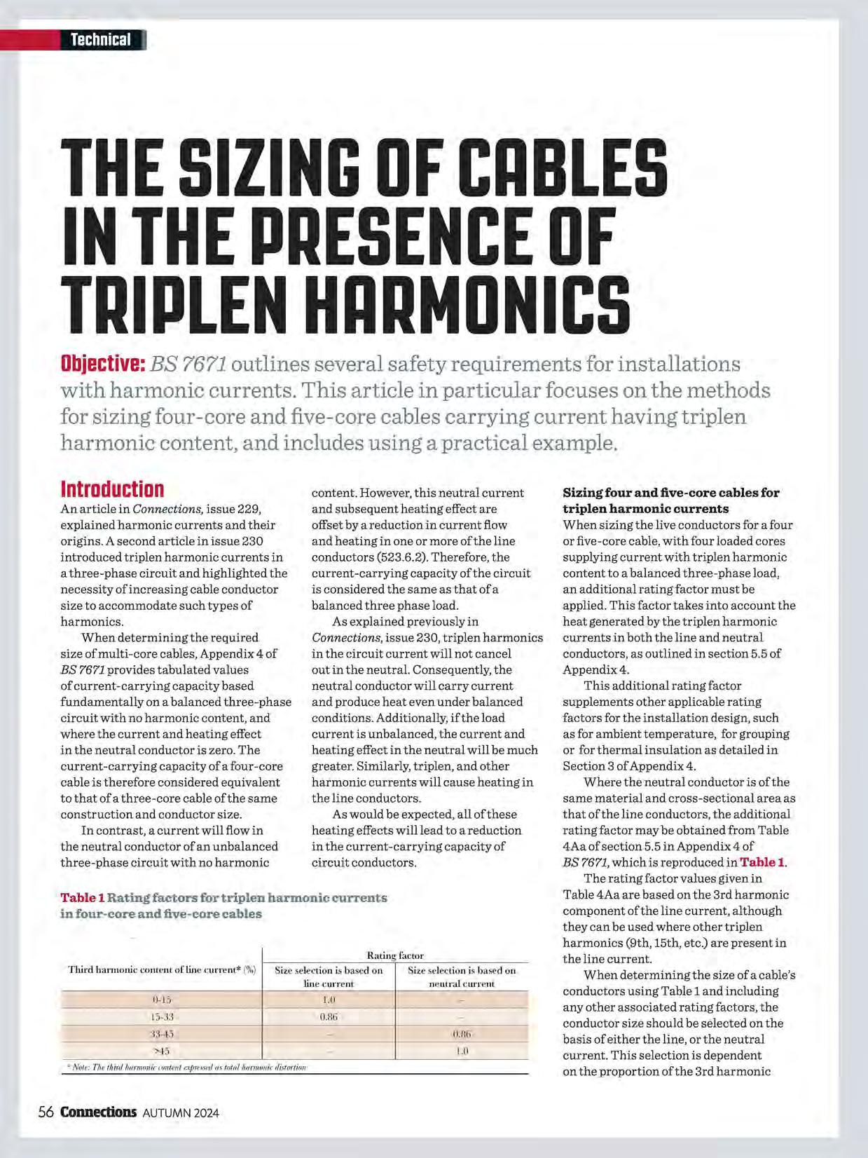
content. However, this neutral current and subsequent heating effect are offset by a reduction in current flow and heating in one or more of the line conductors (523.6.2). Therefore, the current-carrying capacity of the circuit is considered the same as that of a balanced three phase load.
As explained previously in Connections, issue 230, triplen harmonics in the circuit current will not cancel out in the neutral. Consequently, the neutral conductor will carry current and produce heat even under balanced conditions. Additionally, if the load current is unbalanced, the current and heating effect in the neutral will be much greater. Similarly, triplen, and other harmonic currents will cause heating in the line conductors.
As would be expected, all of these heating effects will lead to a reduction in the current-carrying capacity of circuit conductors.
Sizing four and five-core cables for triplen harmonic currents
When sizing the live conductors for a four or five-core cable, with four loaded cores supplying current with triplen harmonic content to a balanced three-phase load, an additional rating factor must be applied. This factor takes into account the heat generated by the triplen harmonic currents in both the line and neutral conductors, as outlined in section 5.5 of Appendix 4.
This additional rating factor supplements other applicable rating factors for the installation design, such as for ambient temperature, for grouping or for thermal insulation as detailed in Section 3 of Appendix 4.
Where the neutral conductor is of the same material and cross-sectional area as that of the line conductors, the additional rating factor may be obtained from Table 4Aa of section 5.5 in Appendix 4 of BS 7671, which is reproduced in Table 1.
The rating factor values given in Table 4Aa are based on the 3rd harmonic component of the line current, although they can be used where other triplen harmonics (9th, 15th, etc.) are present in the line current.
When determining the size of a cable's conductors using Table 1 and including any other associated rating factors, the conductor size should be selected on the basis of either the line, or the neutral current. This selection is dependent on the proportion of the 3rd harmonic
content present in the line current. If the triplen harmonic content:
• Does not exceed 33 %, sizing should be based on the line current, as this current will be greater than the current in the neutral.
• Exceeds 33 %, sizing should be based on the neutral current, as this current will then be greater than the line current.
The following example demonstrates the use of the rating factor chosen from Table 1.
A three-phase, four-wire circuit is designed to carry a load with a fundamental line current of 60 A. This circuit will be installed using a four-core armoured 90°C thermosetting insulated cable. However, the switchgear connected to the cable is not suitable for conductors operating above 70°C. As a result, the conductor size for the cable must be based on the current ratings for a four-core armoured 70°C thermoplastic insulated cable (512.1.5), as provided in Table 4D4A of Appendix 4 of BS 7671.
The cable is to be installed on a perforated cable tray (Reference Method E of section 7.1of Appendix 4) alongside four other circuits (C8 =0.75, from Table 4Cl). The expected ambient temperature is 40°C (C. = 0.87 from Table 4Bl). Overcurrent protection is to be provided by a BS EN 60898-1 circuit-breaker installed in both the line and neutral conductors.
Determine the minimum size of cable that meets the requirements of BS 7671 for current-carrying capacity for each of the following four load conditions:
1. A load that does not produce any 3rd harmonic content.
2. A load with a 3rd harmonic current of 25 % of the fundamental current.
3. A load with a 3rd harmonic content of 40 % of the fundamental current.
4. A load with a 3rd harmonic content of 50 % of the fundamental current.
Assume no other harmonic content is present.
The key stages in the calculations are shown in Table 2.
From Table 2, the minimum conductor size required for a four-core cable (or a five-core cable with one core
Table 2 Key stages of calculations
Fundamental line current(/ 11) 3rd harmonic line current / - I, x 111 3,- 100
Design line current
Design neutral current
Guidance from Table 4Aa
Protecti,·e cb·ice rated current (/,,)
Table 4Aa Rating Facwr (C4Aa)
IVIinirnumlabulatcd currcnt-cru·rying capacity required / I,, !(min) C.IAa x Cax Cg
Nearest higher actual 11, from Table 4D4A, col. 5 !Vfinimumconductor size required
functioning as a protective conductor) is 25 mm 2 where h =0 %, 35 mm 2 where h = 25 %, 50 mm 2 where h =40 %, or 50 mm 2 where h =50 %.
However, to meet the requirements for voltage drop in the circuit, larger conductor sizes may be required.
When a range of harmonic currents is present
The method outlined in Section 5.5 of Appendix 4 only takes account oftriplen harmonic content and the resulting heating effect in both the line and neutral conductors.
However, if the load characteristics result in significant levels of other harmonics (such as the 5th, 7th etc), their heating effect on the line conductor should also be considered.
Section 5.6 suggests that for cables with conductors of a cross-sectional area less than 50 mm 2, the effect of other harmonic currents can be accounted for by applying a rating factor (CJ to the fundamental design current: 2 2 2 C Jl +Jh5
Where:
I1 = 50 Hz current
15 = 5th harmonic current
hn =n th harmonic current
It is worth noting that Section 5.6 uses the
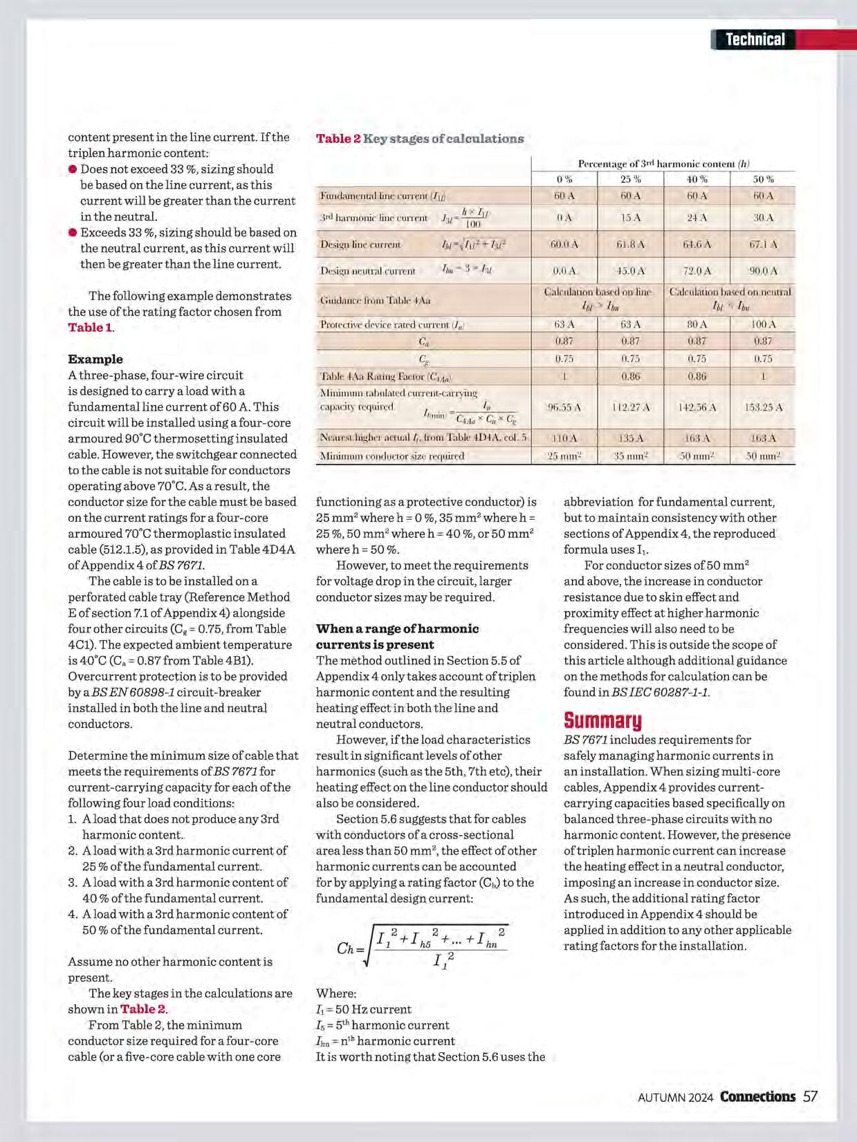
abbreviation for fundamental current, but to maintain consistency with other sections of Appendix 4, the reproduced formula uses I1.
For conductor sizes of 50 mm 2 and above, the increase in conductor resistance due to skin effect and proximity effect at higher harmonic frequencies will also need to be considered. This is outside the scope of this article although additional guidance on the methods for calculation can be found inBSIEC 60287-1-1.
BS 7671 includes requirements for safely managing harmonic currents in an installation. When sizing multi-core cables, Appendix 4 provides currentcarrying capacities based specifically on balanced three-phase circuits with no harmonic content. However, the presence oftriplen harmonic current can increase the heating effect in a neutral conductor, imposing an increase in conductor size. As such, the additional rating factor introduced in Appendix 4 should be applied in addition to any other applicable rating factors for the installation.
Objective:Live testing is permitted, but only where all three conditions of Regulation 14 of the Electricity at Work Regulations 1989 have been met. This article summarises these conditions as they relate to live testing activities.
Regulation 14 of the Electricity at Work Regulations 1989 (EWR) states that:
No person shall be engaged in any work activity on or so near any live conductor (other than one suitably covered with insulating material so as to prevent danger) that danger may arise unless:
(a) it is unreasonable in all the circumstances for it to be dead; and
(b) it is reasonable in all the circumstances for him to be at work on or near it while it is live; and
(c) suitable precautions (including where necessary the provision of suitable protective equipment) are taken to prevent injury.
This regulation applies to all activities during which it is necessary to work in close proximity to energised and exposed or inadequately insulated live parts where this may foreseeably give rise to danger. This would include activities such as carrying out the safe isolation procedure, checking the polarity of an incoming supply and testing earth fault loop impedance or RCD functionality. This is confirmed in paragraph 207 of The Electricity at Work Regulations 1989. Guidance on Regulations (HSR25) published by the Health and Safety Executive (HSE).
Let's consider the three requirements in Regulation 14 that must be met before live work may proceed.
1. It is unreasonable in all the circumstances for the conductor to bedead
It is reasonable for testing to take place on or near to a live conductor where the
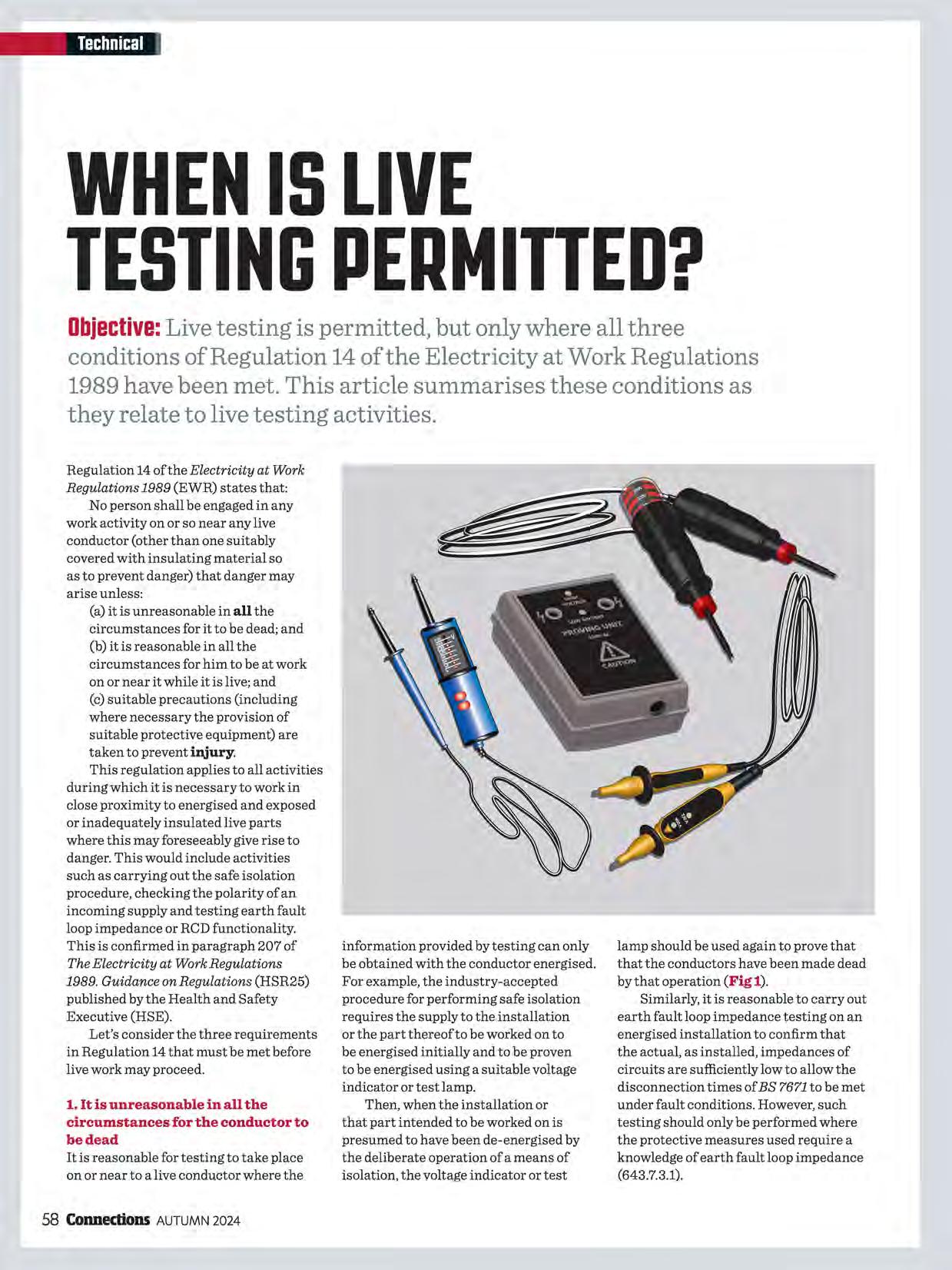
information provided by testing can only be obtained with the conductor energised. For example, the industry-accepted procedure for performing safe isolation requires the supply to the installation or the part thereof to be worked on to be energised initially and to be proven to be energised using a suitable voltage indicator or test lamp.
Then, when the installation or that part intended to be worked on is presumed to have been de-energised by the deliberate operation of a means of isolation, the voltage indicator or test
lamp should be used again to prove that that the conductors have been made dead by that operation (Fig 1).
Similarly, it is reasonable to carry out earth fault loop impedance testing on an energised installation to confirm that the actual, as installed, impedances of circuits are sufficiently low to allow the disconnection times of BS 7671 to be met under fault conditions. However, such testing should only be performed where the protective measures used require a knowledge of earth fault loop impedance (643.7.3.1).
Fig 2 Voltage indicator with integral self-test facility
Fig 1 Voltage detector used to check that there is no dangerous voltage present
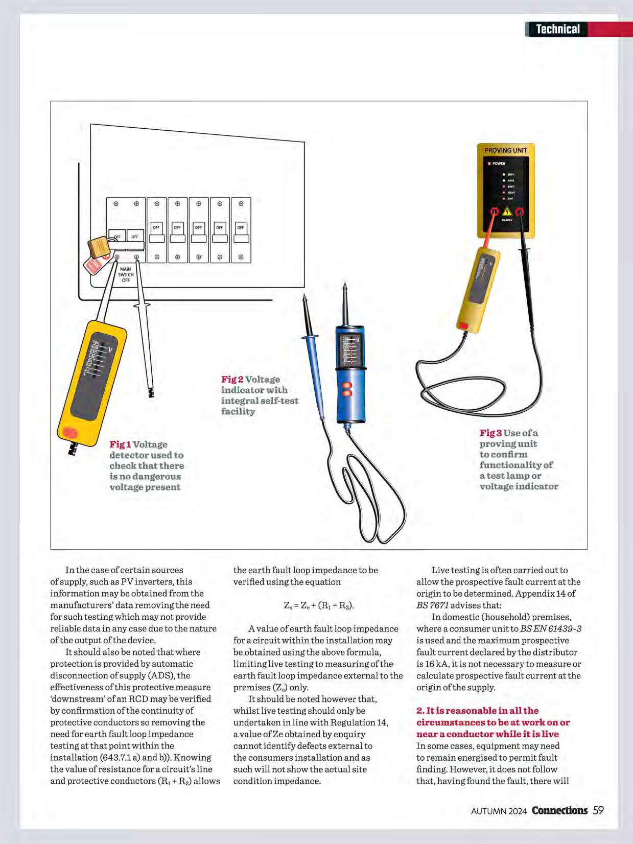
Fig3Useofa proving unit to confirm functionality of a test lamp or voltage indicator
In the case of certain sources of supply, such as PV inverters, this information may be obtained from the manufacturers' data removing the need for such testing which may not provide reliable data in any case due to the nature of the output of the device.
It should also be noted that where protection is provided by automatic disconnection of supply (ADS), the effectiveness of this protective measure 'downstream' of an RCD may be verified by confirmation of the continuity of protective conductors so removing the need for earth fault loop impedance testing at that point within the installation (643.7.1 a) and b)). Knowing the value ofresistance for a circuit's line and protective conductors (R1+ R 2) allows
the earth fault loop impedance to be verified using the equation
A value of earth fault loop impedance for a circuit within the installation may be obtained using the above formula, limiting live testing to measuring of the earth fault loop impedance external to the premises (Z.) only.
It should be noted however that, whilst live testing should only be undertaken in line with Regulation 14, a value ofZe obtained by enquiry cannot identify defects external to the consumers installation and as such will not show the actual site condition impedance.
Live testing is often carried out to allow the prospective fault current at the origin to be determined. Appendix 14 of BS 7671 advises that:
In domestic (household) premises, where a consumer unit to BS EN 61439-3 is used and the maximum prospective fault current declared by the distributor is 16 kA, it is not necessary to measure or calculate prospective fault current at the origin of the supply.
2. It is reasonable in all the circumstances to be at work on or near a conductor while it is live In some cases, equipment may need to remain energised to permit fault finding. However, it does not follow that, having found the fault, there will
necessarily be justification for subsequent repair work to be carried out live (HSR25: paragraph 220).
Justification for exposing live terminals solely to verify the correct operation of a voltage indicator or test lamp before and after use is arguably more problematic in terms of this condition. Whilst the use of a test lamp or voltage indicator on an energised circuit to prove dead is essential and unavoidable, it is possible to confirm the functionality of such test devices prior to and after such testing by either the integral self-test facility of some voltage indicators (Fig 2), or by the use of a suitable proprietary proving unit (Fig 3).
Such methods not only remove the need to expose live parts until it is necessary to confirm that conductor is energised, but also the need to access another live part after the conductor has been isolated to confirm that the test device is still functioning correctly.
3. Suitable precautions are taken to prevent injury
In the context oflive testing, suitable precautions to prevent injury include:
• only allowing suitably competent persons who are familiar with the type of installation, the test devices to be used and the work activities to be performed to carry out testing, and
• the use of suitable testing devices meeting the requirements of relevant product standards and the recommendations given in Electrical test equipment for use on low voltage electrical systems (GS38), and
• the use of suitable protective equipment as appropriate to the exposure risk (HSR25: paragraphs 221 and 222).
It is essential that all the above precautions are maintained over time (HSR25: paragraph 223). Testing skills need to be refreshed and instruments, test leads, probes and protective equipment need to be inspected before each use to confirm their continued suitability.
Where for example routine testing or fault finding is carried out on energised
equipment, a suitable precaution might be to cover live parts with a transparent insulating screen in which holes are drilled to enable access to be made to test points. In some cases, it might be appropriate to bring leads out from a test point, to a suitable multi-pin socket-outlet, permitting the use oftest equipment in a manner that is not only safer but may also reduce the time required to carry out the necessary testing.
Persons carrying out work on or near a live conductor have a legal responsibility for the safety of other persons who may be affected by their actions (EWR: regulation 3). They must therefore take suitable precautions to ensure effective control of the area where live testing is being carried out.
A risk assessment should be carried out to determine an appropriate course of action to suit the particular circumstances. A record of this assessment will be required where an employer has five or more employees. The guidance provided in The Electricity at Work Regulations 1989. Guidance on Regulations (HSR25), Electricity at work, safe working practices (HSG85) and Safety in electrical testing at work (INDG354) published by the HSE are invaluable to anyone carrying out live testing activities or having responsibility for those carrying out such work.
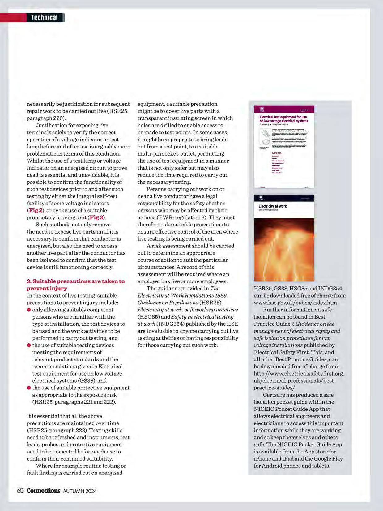
HSR25, GS38, HSG85 and INDG354 can be downloaded free of charge from www.hse.gov.uk/pubns/index.htm
Further information on safe isolation can be found in Best Practice Guide 2 Guidance on the management of electrical safety and safe isolation procedures for low voltage installations published by Electrical Safety First. This, and all other Best Practice Guides, can be downloaded free of charge from http://www.electricalsafetyfirst.org. uk/electrical-professionals/bestpractice-guides/
Certsure has produced a safe isolation pocket guide within the NICEIC Pocket Guide App that allows electrical engineers and electricians to access this important information while they are working and so keep themselves and others safe. The NICEIC Pocket Guide App is available from the App store for iPhone and iPad and the Google Play for Android phones and tablets.

Tried 6 Tested
Cost Effective
Time Saving
Memshield1S2
Available From Your Local
Electrical Wholesaler
Themainproductrangesthatareavailableinclude:
MBH. MCH. MDH 6. MDL 1,2.3 and 4 pole MCBs and MR30 RCBO pods for use with MEMSHIELD 2 boards and Bill Talisman Plus Boards.
Memera 2000 range of domestic consumer unit MCBs plus 08, MB. MC. MD 6K 6. 9K used with MEMSHIELD 1
MadeintheoriginalUKMEMHolyheadFactory

In the following multiple-choice questions you should choose one of the four options that, in your opinion, is the correct answer. You may find it useful to refer to the technical articles in this issue of Connections and BS 7671:2018+A2:2022. The answers to the questions, accompanied by a briefrationale, can be found at the end of the technical section.
1. The additional rating factor introduced in Table 4Aa of Appendix 4 is used to take account of?
a) Voltage drop in the circuit caused by triplen harmonics
b) Cables grouped with other cables
c) The heating effect caused bytriplen harmonics
d) An increase in ambient temperature
2. In an unbalanced three-phase circuit with no harmonic content, what is the effect on the neutral conductor's heating?
a) There is no offset by a reduction in the current and heating in the line conductors
b) It is offset by a reduction in the current and heating in the line conductors
c) It remains the same as in a balanced three-phase circuit
d) The result is that there is no current flow in the neutral conductor
3. When determining the size of a cable's conductors, what factor influences whether sizing is based on either the line current or neutral current?
a) Whether current flow in the threephase circuit is balanced
b) Whether current flow in the threephase circuit is unbalanced
c) The proportion of the 3rd harmonic content
d) The proportion of the 1st harmonic content
4. What is the correction factor to account for load temperature when comparing measured earth fault loop impedance (Zs) with the maximum permitted earth fault loop impedance of the protective device?
a) 0.75
b) 0.9
c) 0.65
d) 0.8
5. In an installation with a TN earthingarrangementthathasa nominal voltage to earth (U0} of 230 V, what is the disconnection time for a 40 A circuit serving only fixed equipment?
a) 0.2s
b) 0.4s
c) 5s
d) 0.8s
6. The symbol Iadenotes the:
a) Current causing operation of the protective device within the specified time
b) Design current of the circuit
c) Rated current or current setting of protective device
d) Rated output current of a generating set.
7. Switch-disconnectors conform to which product standard?
a) BS7671
b) BS EN 60898
c) BS EN 62606
d) BSENIEC60947-3

8. WhichofthefollowingUtilization Categories is suitable for use with single PV strings where reverse currents and significant overcurrent are not possible?
a) DC-PV0
b) DC-PVl
c) DC-PV2
d) DC-PV3
9. When calculating the short-circuit maximum current (Isc~ for use when selecting equipment PV array equipment, what value is used as a multiplier to take account of actual irradiance being higher than that given in standard test conditions?
a) 1.25
b) 1.35
c) 1.45
d) 1.55
10. The maximum prospective shortcircuit or earth-fault current in a circuit should not exceed:
a) The current-carrying capacity of the circuit conductors
b) The design current of the circuit when fully loaded
c) The current causing effective operation of the protective device
d) The rated breaking capacity of any associated protective device
11. Which one of the following statements correctly represents the relationship between let-through energy and the thermal constraints of the cable conductors?
a) Ft> k 2 S2
b) I2t<k 2 S2
c) It 2 > k 2 S2
d) It 2 < k 2 S2
12.Live testing to determine earth fault loop impedance should only be carried out where:
a) The protective measures employed require a knowledge of this information
b) It is necessary to confirm that the information given by the manufacturer of an inverter is correct
c) Protection by automatic disconnection of supply (ADS) for a circuit is provided by anRCD
d) The test is carried out in close proximity to a supply transformer
Answers and rationale
Q A Explanation
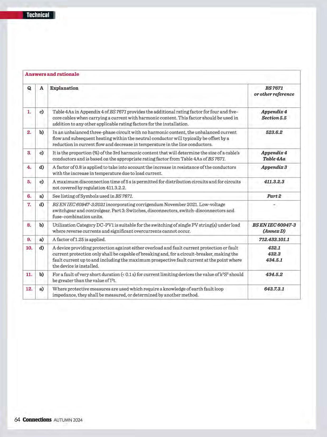
1. c) Table 4Aa in Appendix 4 of BS 7671 provides the additional rating factor for four and five- Appendix4 core cables when carrying a current with harmonic content. This factor should be used in Section5.5 addition to any other applicable rating factors for the installation.
2. b) In an unbalanced three-phase circuit with no harmonic content, the unbalanced current
flow and subsequent heating within the neutral conductor will typically be offset by a reduction in current flow and decrease in temperature in the line conductors.
3. c) It is the proportion(%) of the 3rd harmonic content that will determine the size of a cable's Appendix4 conductors and is based on the appropriate rating factor from Table 4Aa of BS 7671.
Table4Aa
4. d) A factor of 0.8 is applied to take into account the increase in resistance of the conductors Appendix3 with the increase in temperature due to load current.
5. c) A maximum disconnection time of 5 s is permitted for distribution circuits and for circuits
not covered by regulation 411.3.2.2.
6. a) See listing of Symbols used in BS 7671. Part2
7. d) BS EN IEC 60947-3:2021 incorporating corrigendum November 2021. Low-voltageswitchgear and controlgear. Part 3: Switches, disconnectors, switch-disconnectors and fuse-combination units.
8. b) Utilization Category DC-PVl is suitable for the switching of single PV string(s) under load BSENIEC60947-3 where reverse currents and significant overcurrents cannot occur. (AnnexD)
9. a) A factor ofl.25 is applied. 712.433.101.1
10. d) A device providing protection against either overload and fault current protection or fault
current protection only shall be capable of breaking and, for a circuit-breaker, making the
fault current up to and including the maximum prospective fault current at the point where
the device is installed.
11. b) For a fault of very short duration (< 0.1 s) for current limiting devices the value ofk 2 S2 should 434.5.2 be greater than the value ofI2t.
12. a) Where protective measures are used which require a knowledge of earth fault loop 643.7.3.1 impedance, they shall be measured, or determined by another method.

Pumpinganelectricalcurrentthroughseawatercanspeeduptherepairof damagedcoralreefs,whichgrowatasnail'space.Usingasmallelectrical chargefromfloating,solar-poweredislandsencouragesmineralsinthe watertocrystalliseonstructures,forminglimestonerockthatisthe perfecthabitatforyoungcorals.NGOReefWatchhasfoundthatwiththis help,coralgrowseventola timesfasterthantheusual0.5cmperyear.

Warehouse packing work can be pretty gruelling, and much ofit is already automated. So why not employ a 'humanoid robot'? Developed by US firmApptronik, Apollo is 5 ft 8 in, can carry 30 kilos and operates on swappable batteries. LEDs in its head, mouth and chest work together "to communicate status", says Apptronik. So when the mouth changes to a spanner, it needs maintenance! Expect to see Apollo in warehouses and manufacturing plants soon, followed by construction, oil and gas, electronics production, retail, home delivery and care of the elderly. Could it then come after the trades?
Electrical signals sent deep into a boy's brain have cut his daytime epilepsy seizures -triggered by abnormal bursts ofelectrical activity in the brain -by 80%. Until now, such seizures were treated with wires running up to the brain from a neurostimulator placed in the chest. In this new treatment two electrodes were inserted in the thalamus, akeyrelay station for neuronal information. A delicate operation, as the margin of error for the lead placement was less than 1 mm,BBCNews says. The leads are connected to the neurostimulator, a 3.5 cm 2 device inserted in the boy's skull. To block or disrupt abnormal electrical signals, the device emits a constant pulse of current. In future, the neurostimulator should respond in real time to changes in brain activity, blocking seizures before they happen.

Aico's free, award-winning Expert Installer training scheme is FIA CPD accredited and is designed to make sure installers have all the information they need to correctly install domestic home life safety systems, including Fire and Carbon Monoxide alarms and Environmental Sensors.

0Connect with fellow professionals eLearn new skills to earn points and receive prizes 0Rewards for members every month
Members of the community are eligible to participate in Aico's free-of-charge City & Guilds Assured Training - Domestic Fire & CO Alarm Systems.