WEEK 8-10 ASSIGNMENT 3
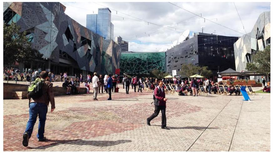
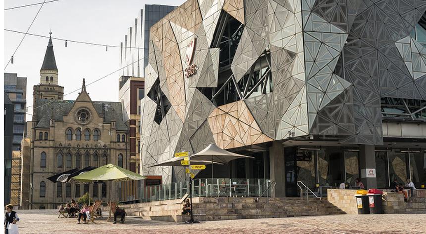
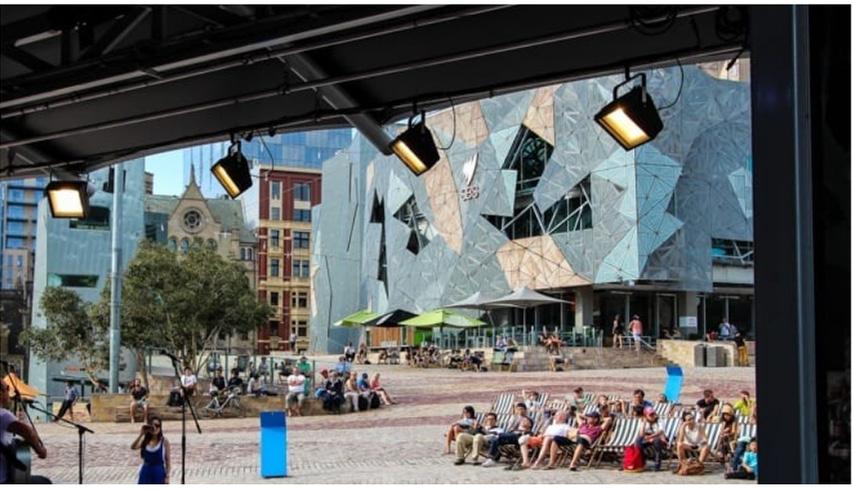
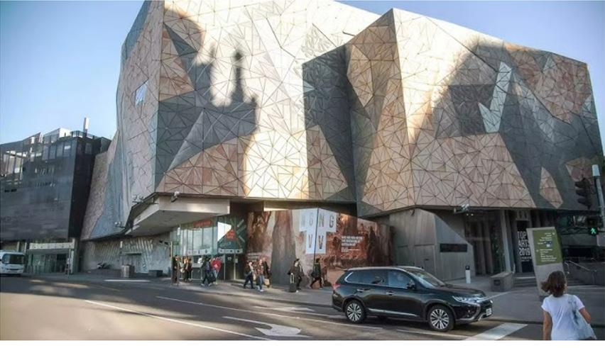
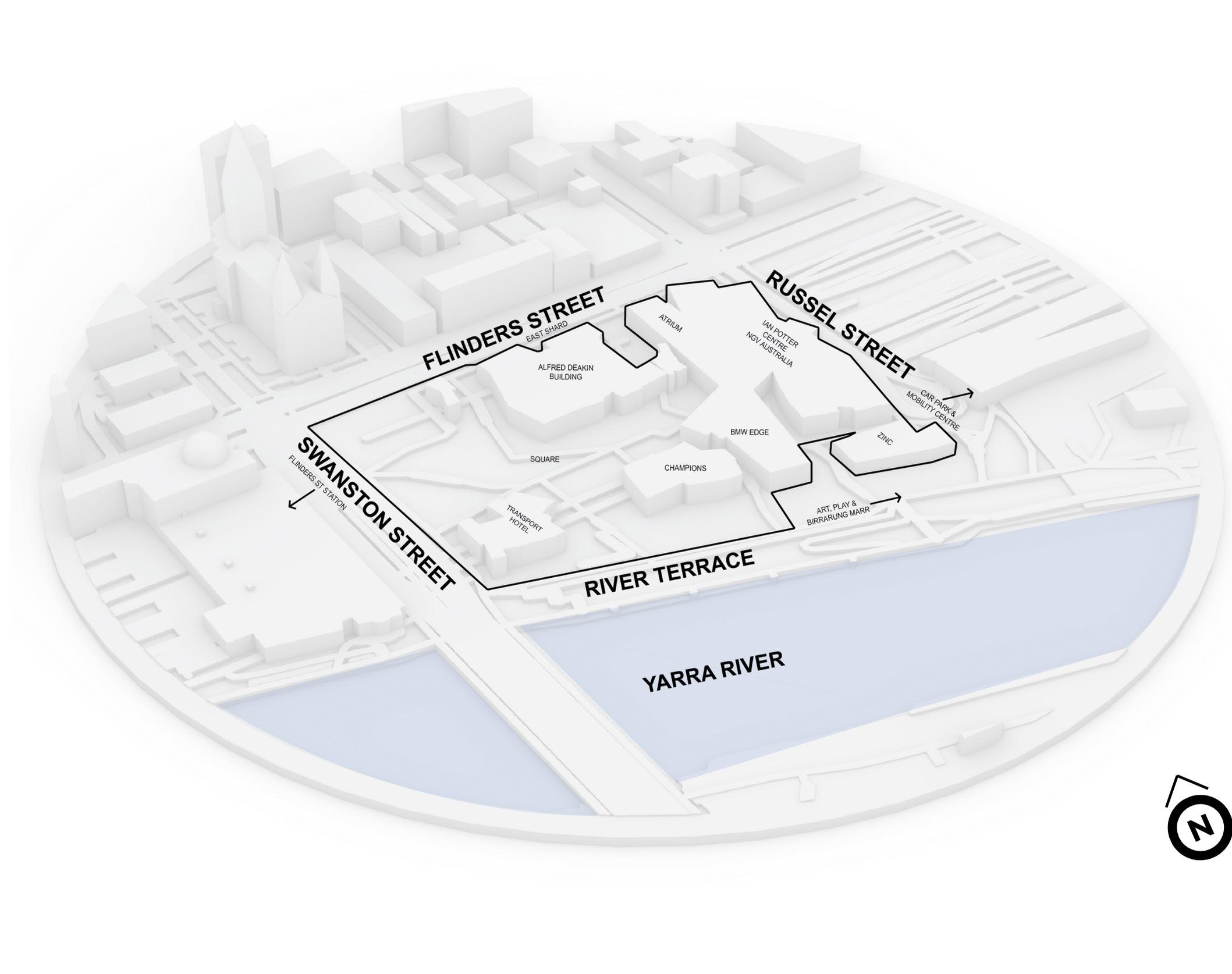
FEDERATION SQUARE, MELBOURNE VIC
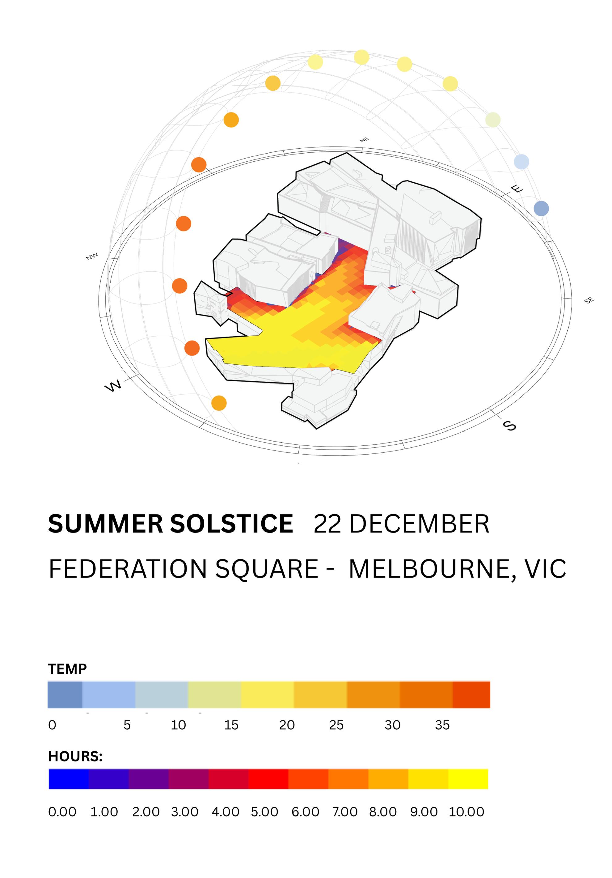
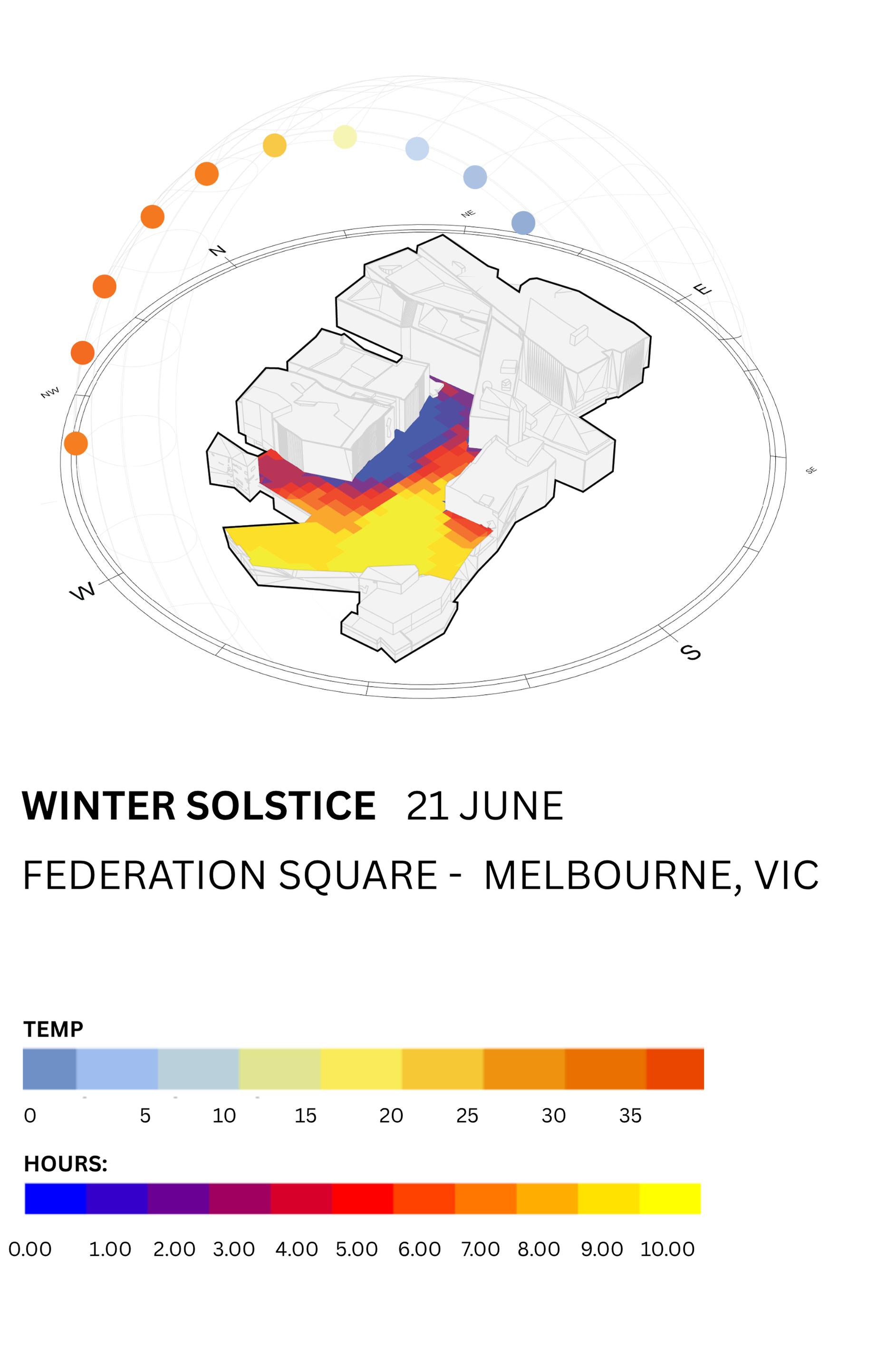
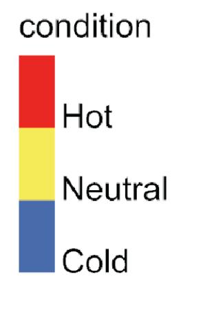
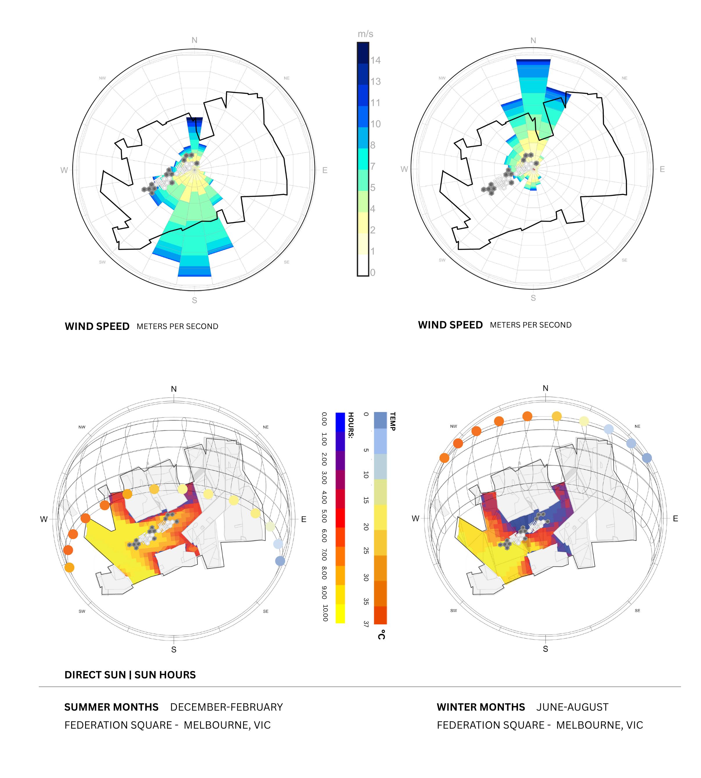
DIRECT SUN HOURS - EXISTING CONDITIONS
FEDERATION SQUARE, MELBOURNE VIC
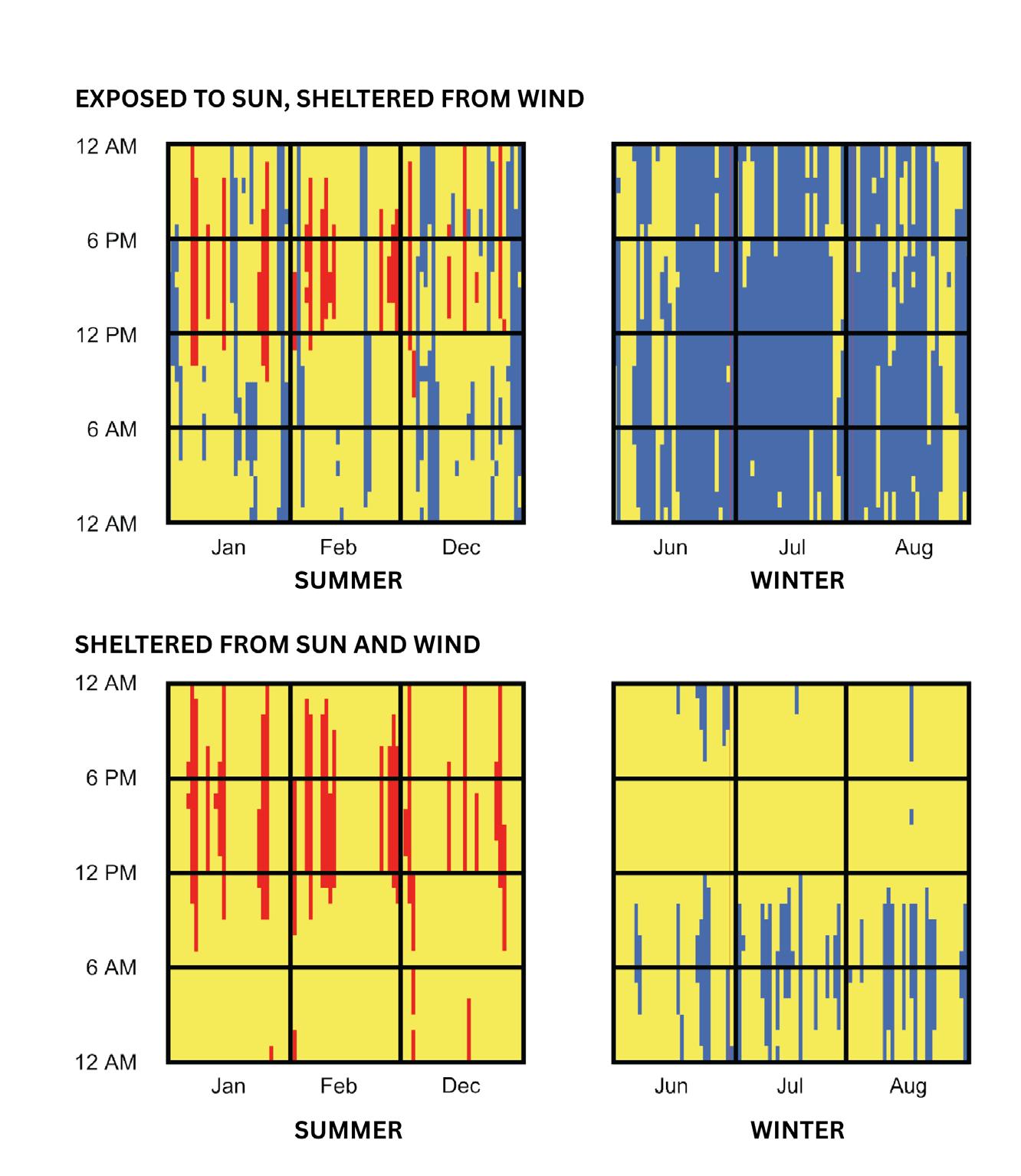
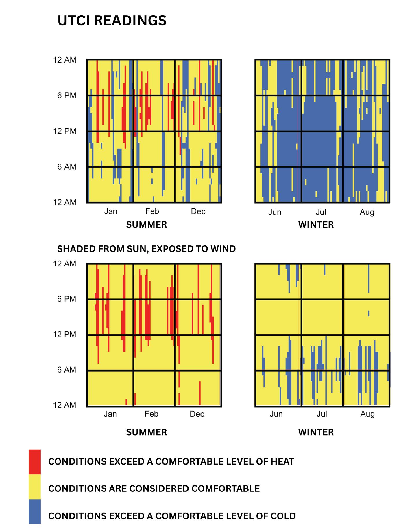
WIND ROSE - EXISTING CONDITIONS
FEDERATION SQUARE, MELBOURNE VIC
FEDERATION SQUARE - FEDERATION SQUARE -
SQUARE

WEEK 8-10 ASSIGNMENT 3
FEDERATION SQUARE, MELBOURNE VIC
DIRECT SUN HOURS - EXISTING CONDITIONS
FEDERATION SQUARE, MELBOURNE VIC
WIND ROSE - EXISTING CONDITIONS
FEDERATION SQUARE, MELBOURNE VIC
FEDERATION SQUARE - FEDERATION SQUARE -
SQUARE
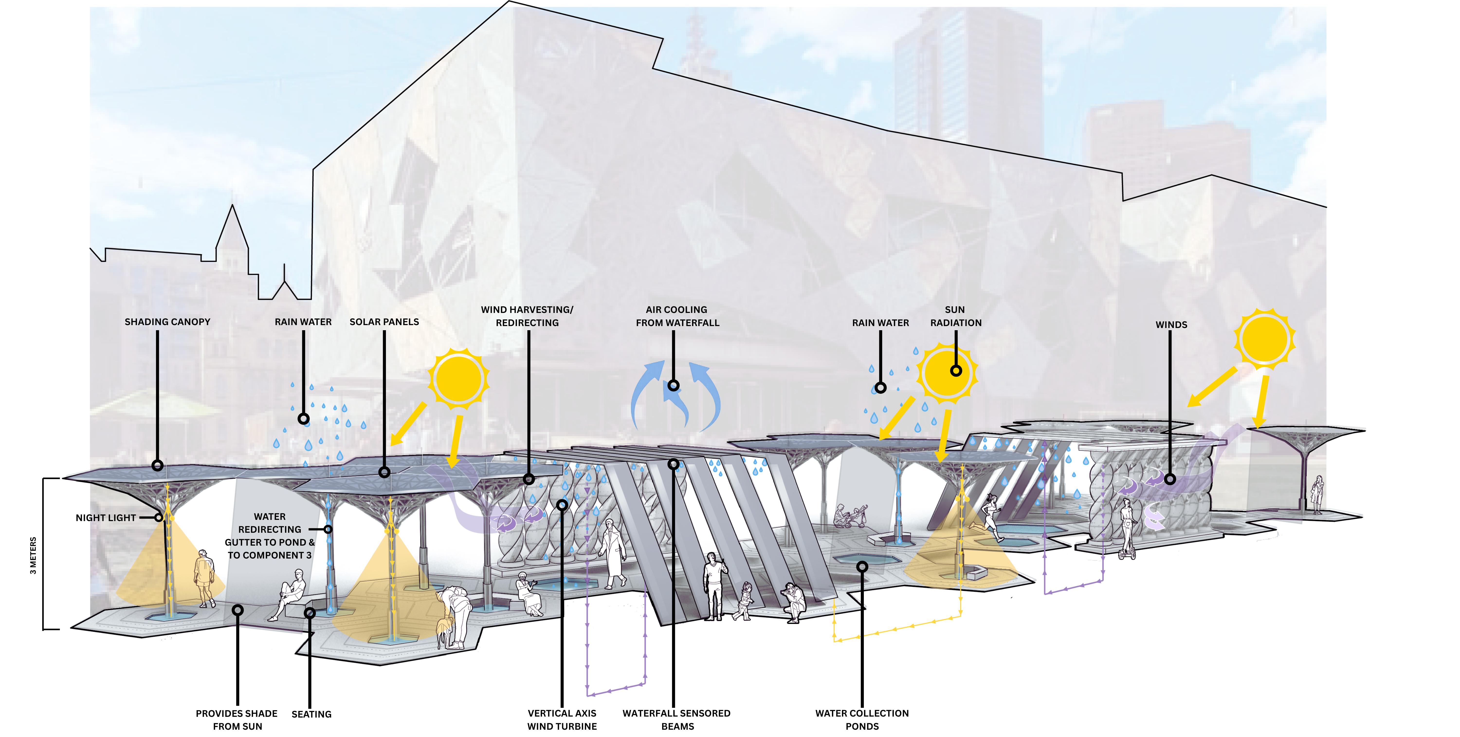
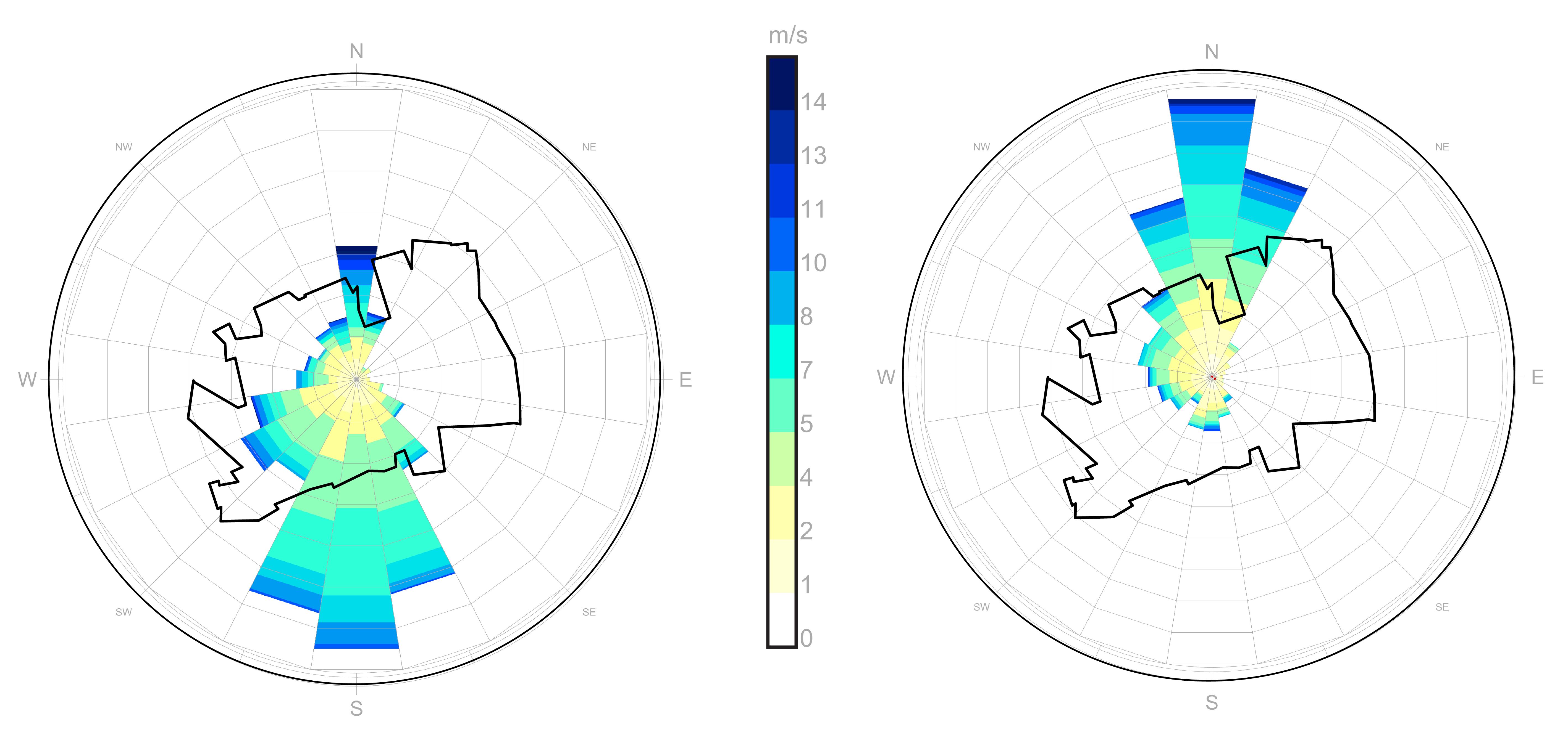
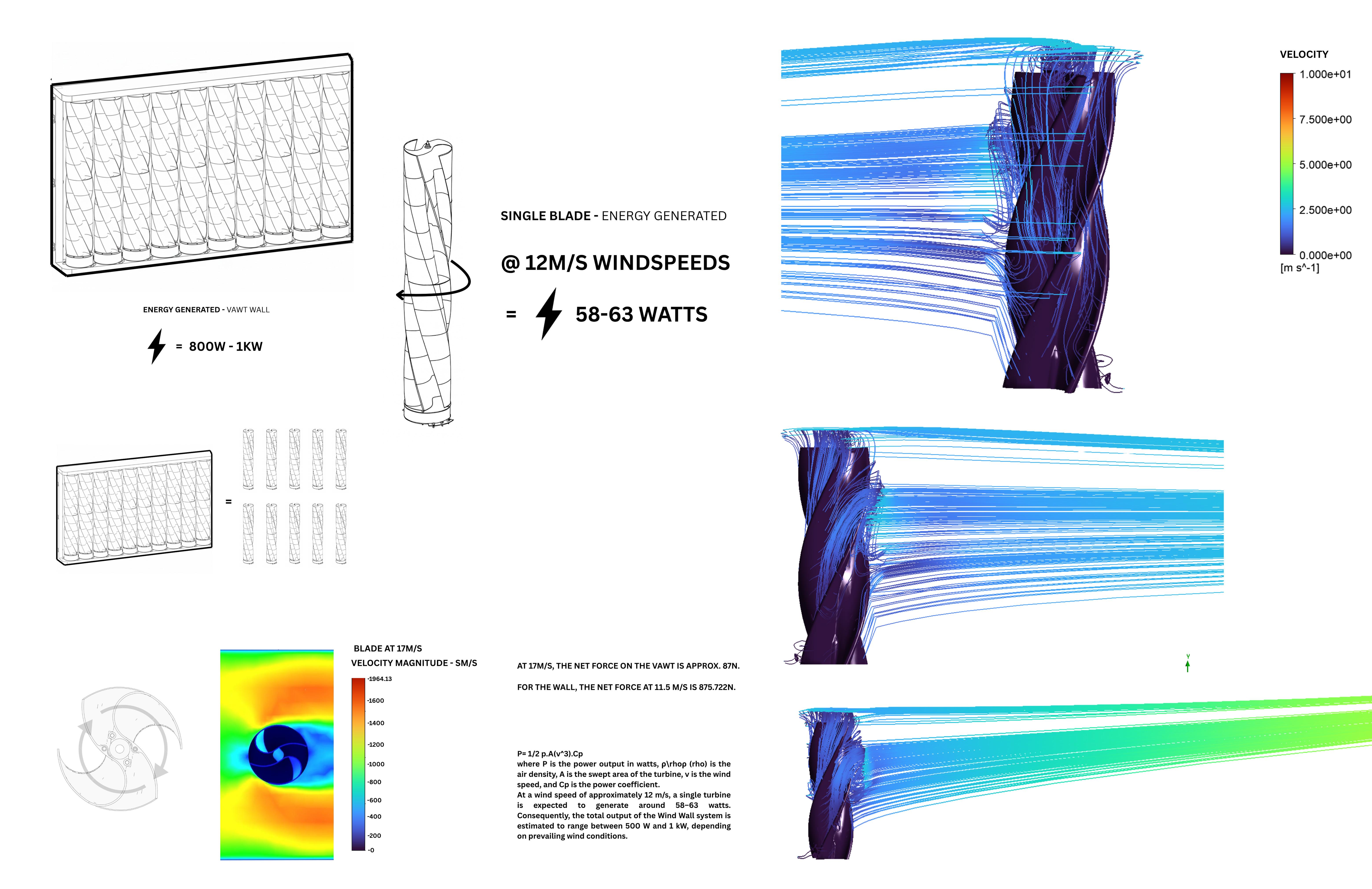
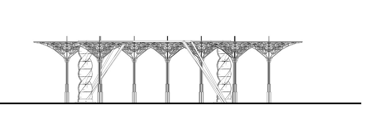
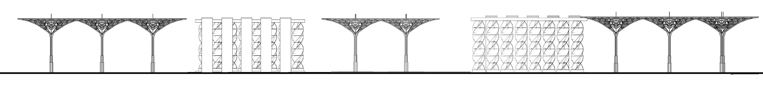
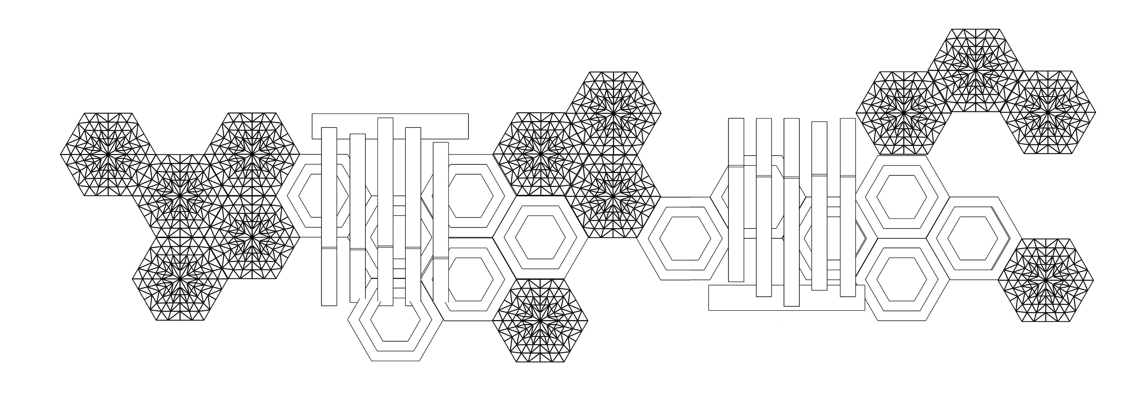
VERTICAL AXIS WIND TURBINES (VAWT)
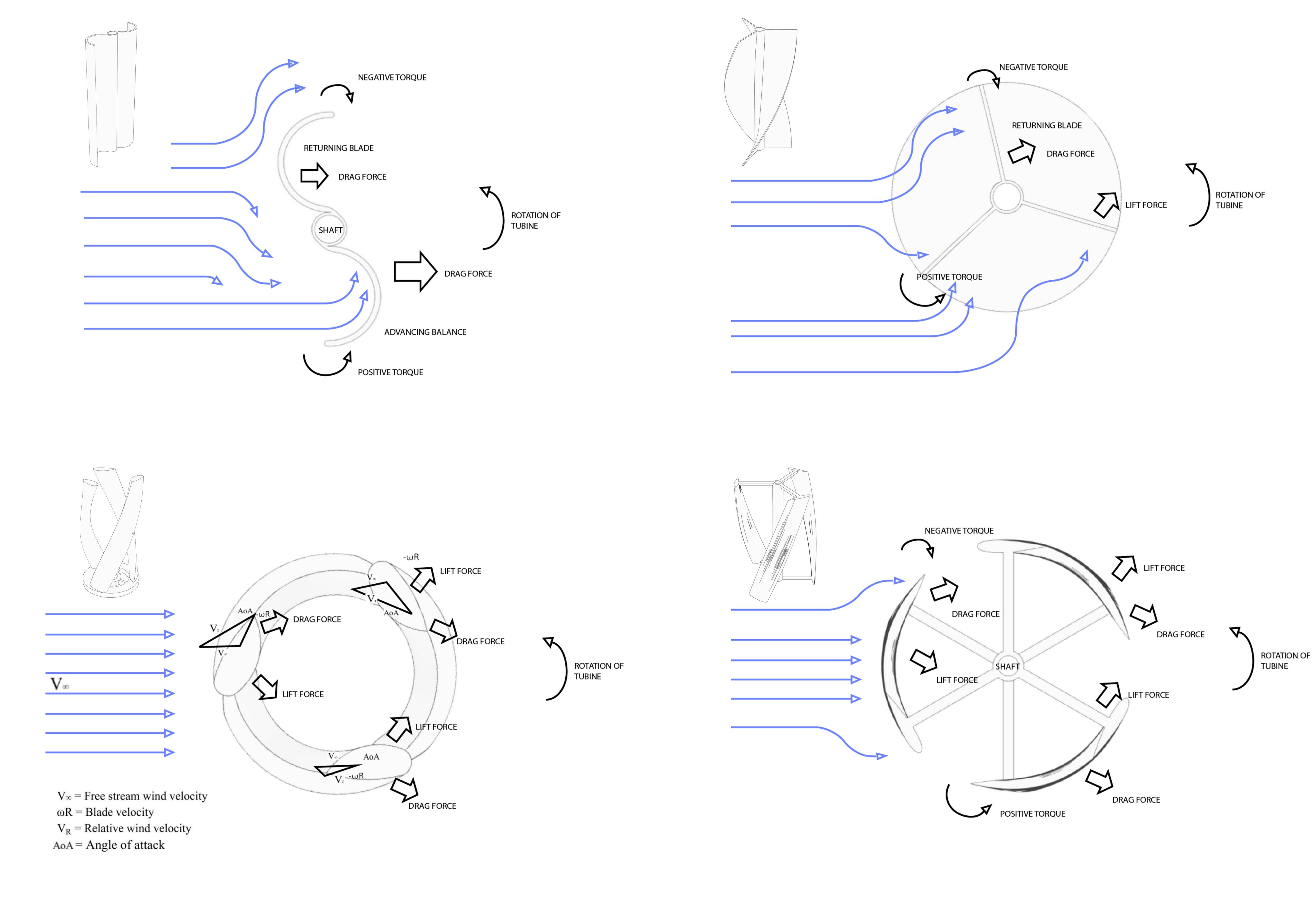
VERTICAL AXIS WIND TURBINES (VAWT)
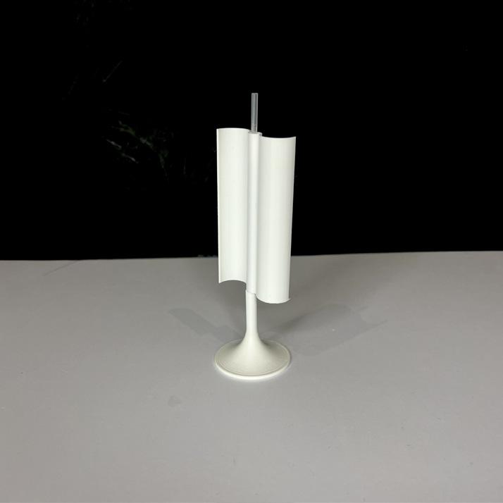
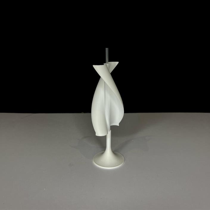
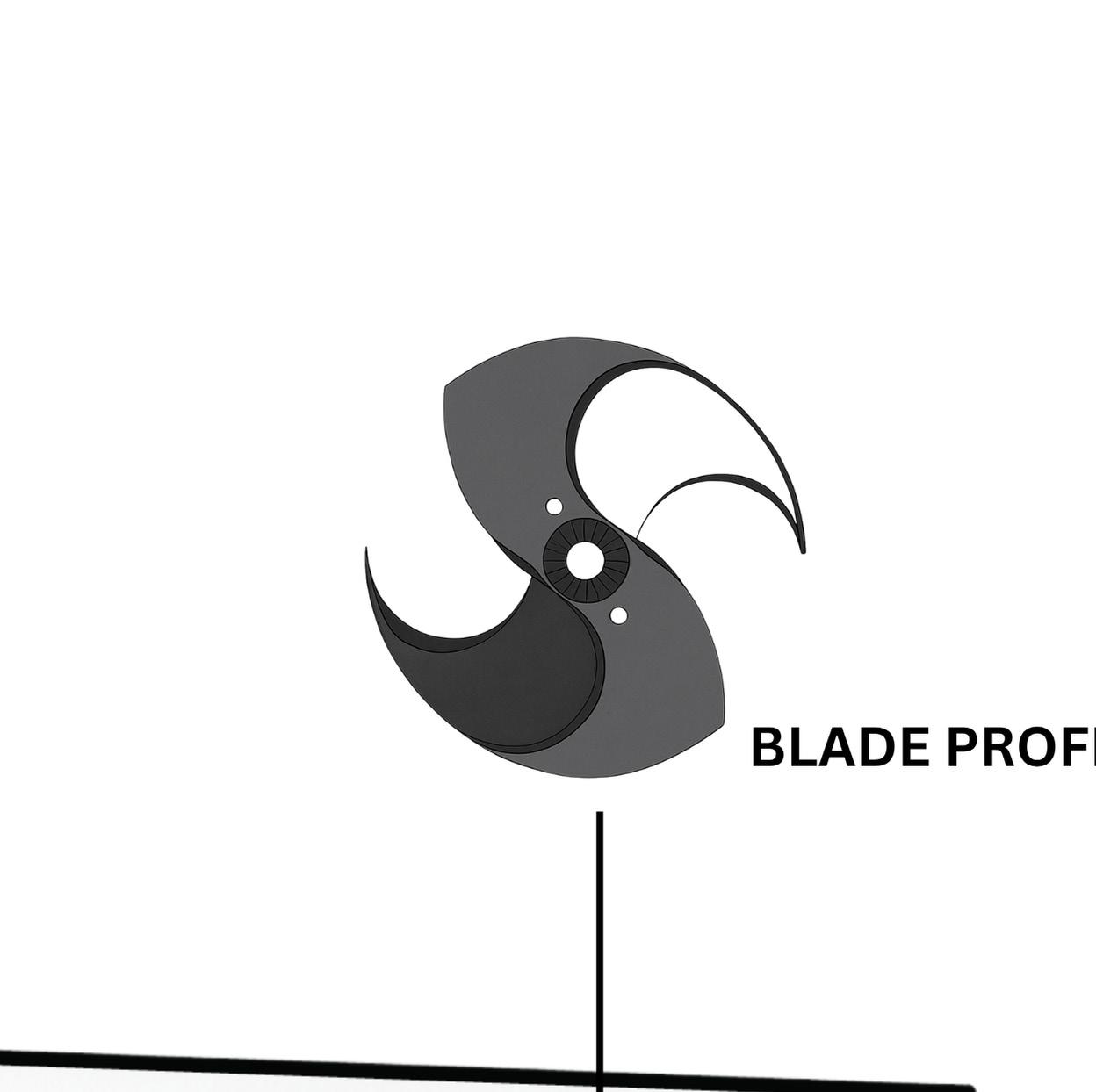

THE UGRINSKY PROFILE
THE UGRINSKY PROFILE METHOD VERTICAL AXIS WIND TURBINES (VAWT)
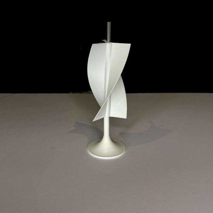
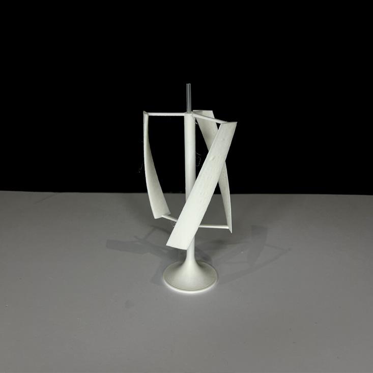
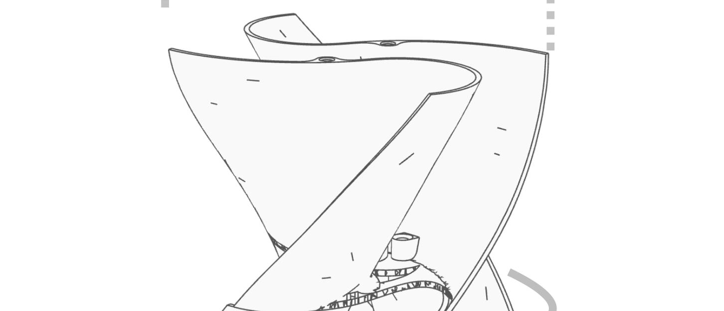
Select the planes and sketch the Ugrinsky blade profile.
After drawing the outline, duplicate it twice in the same sketch, moving the first copy up by 5 cm and the second up by 10 cm.
Rotate the first copied profile by 10° and the second by 20°. Multiple profiles instead of just one allows the blade surface to form smoothly and continuously along its length when lofted
Making two such profiles ensures that when we use the ‘Loft’ tool, it makes continuous blade length wise/
Once the loft is created, mirror it twice to form the second half of the blade. Then copy that blade section, move it up by 10 cm, and rotate it by 20°.
Repeat this method as needed.
I chose the Ugrinsky profile for its ability to perform well and for its capacity to produce positive, steady torque from every position. This is especially important since fluctuating torque can produce a ‘pulsing’ effect on the shaft, greatly diminishing its performance and efficiency.
Moreover, the Ugrinsky design has a maximum power coefficient of 0.170, which is a considerable 54.5% improvement over the Savonius turbine (see references).
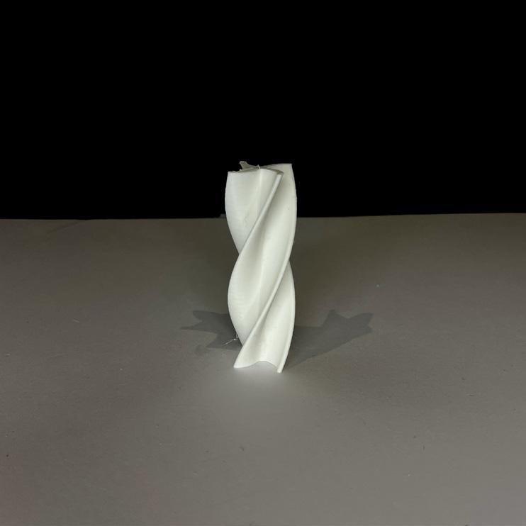
METHOD
VERTICAL AXIS WIND TURBINES (VAWT)
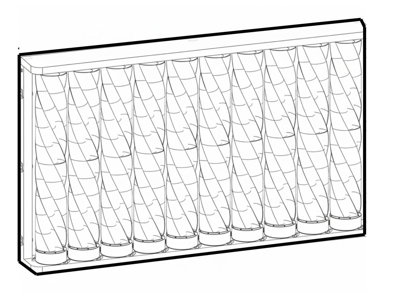
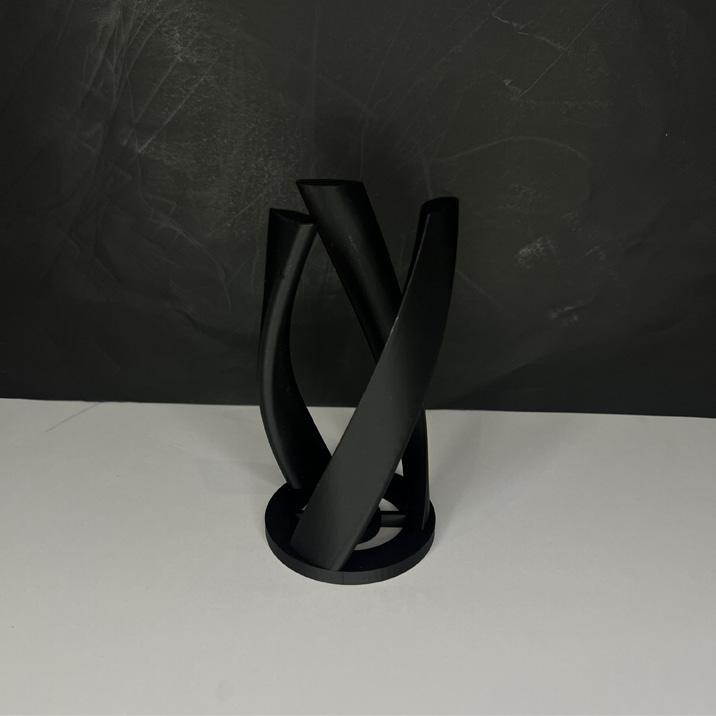
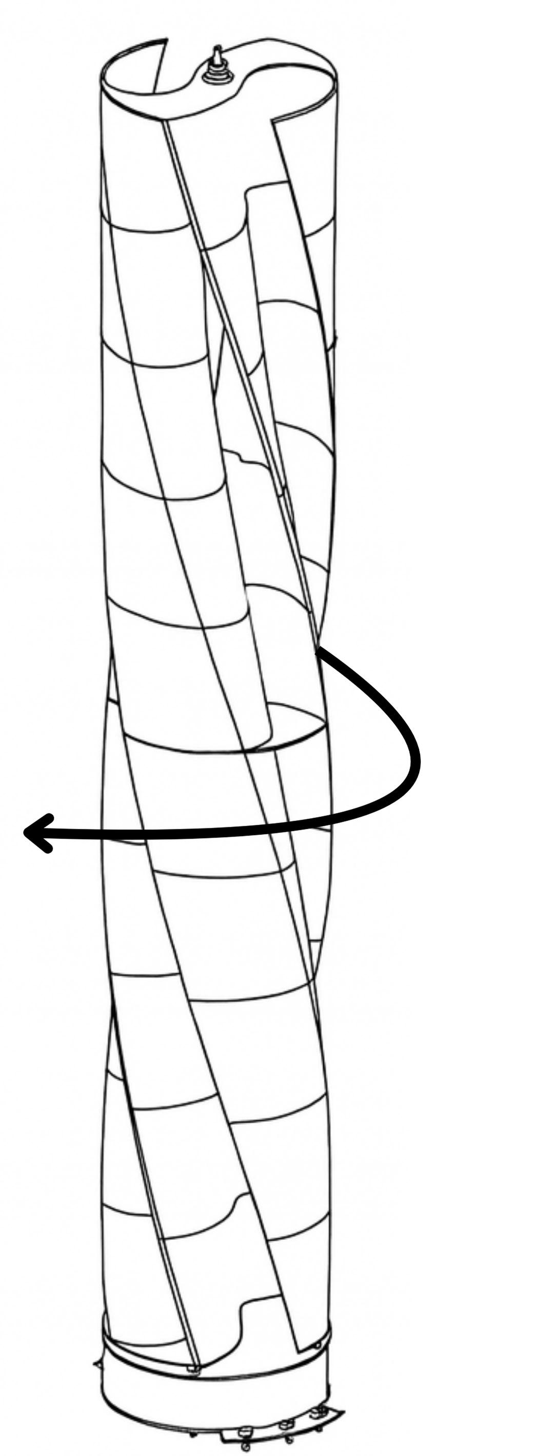
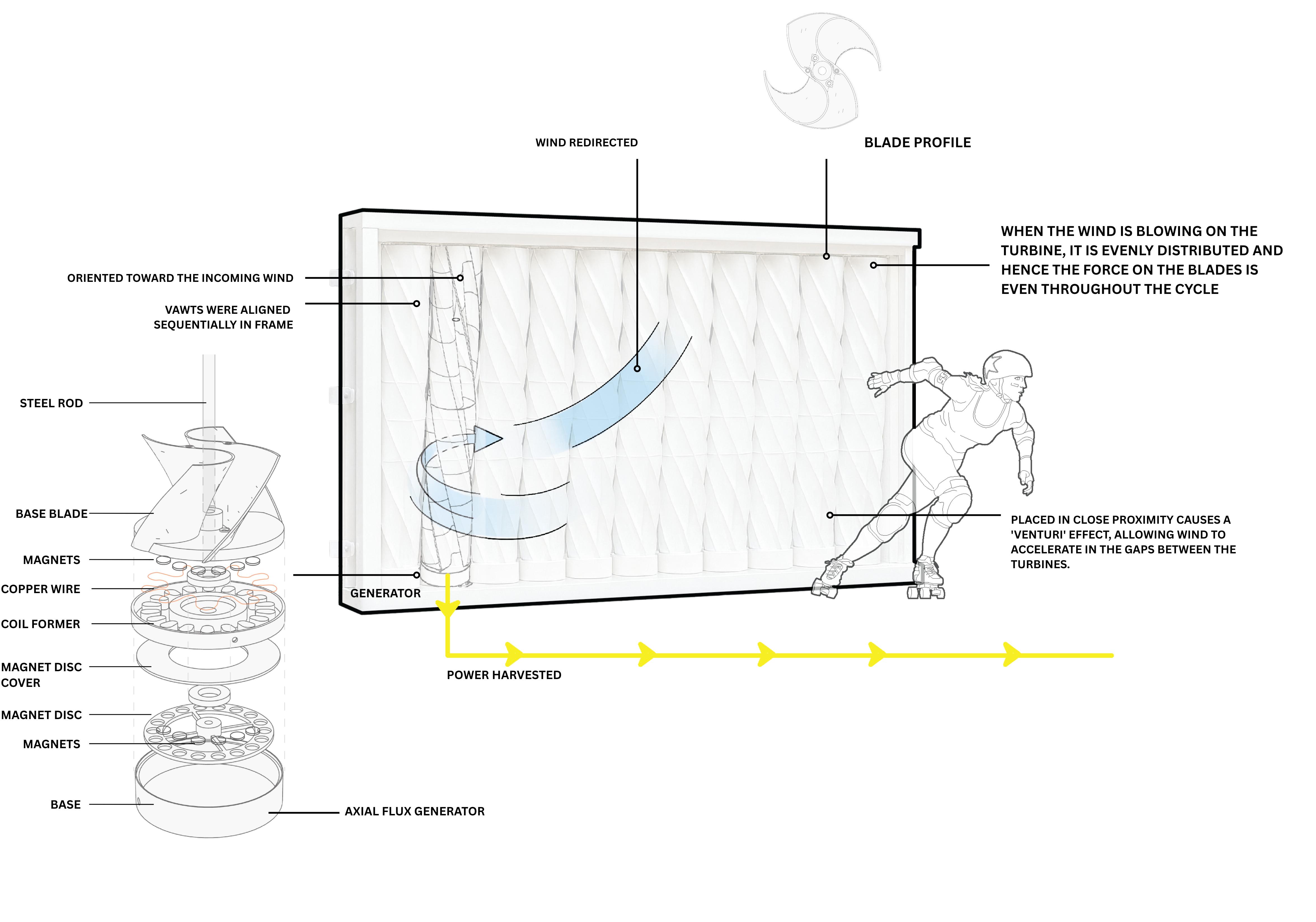
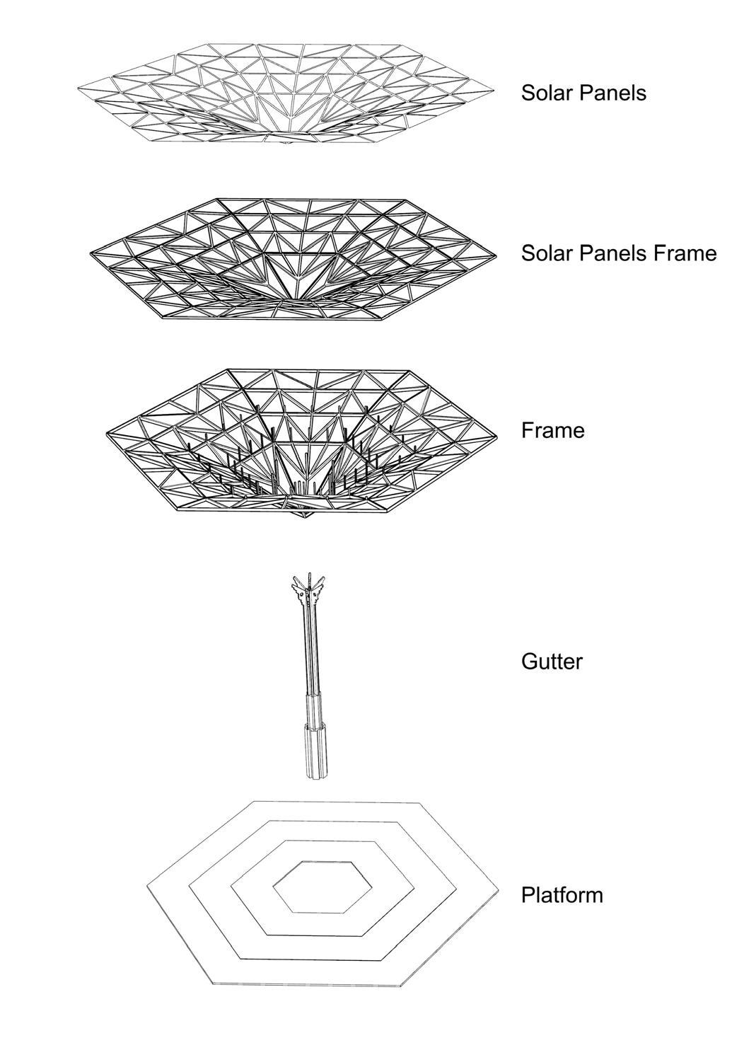
The blades are modelled to become modular and stackable, meaning the overall blade can be stacked to any height. This allows 3d printers to pint the model to scale in sections.
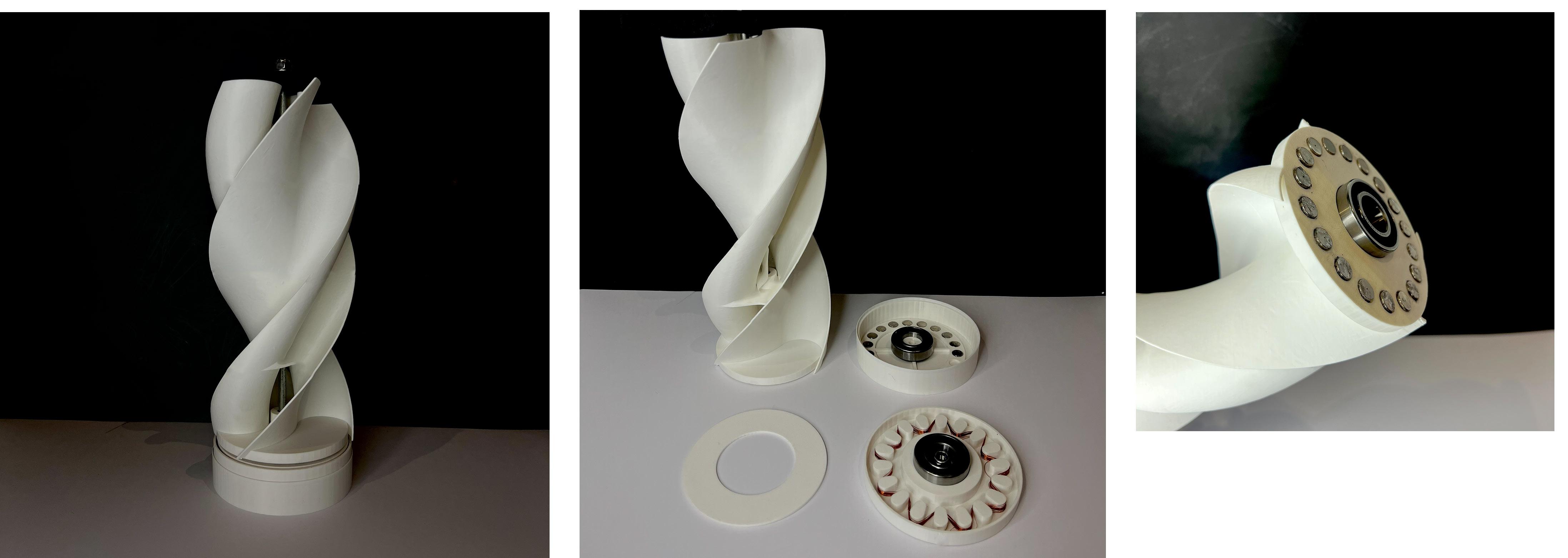
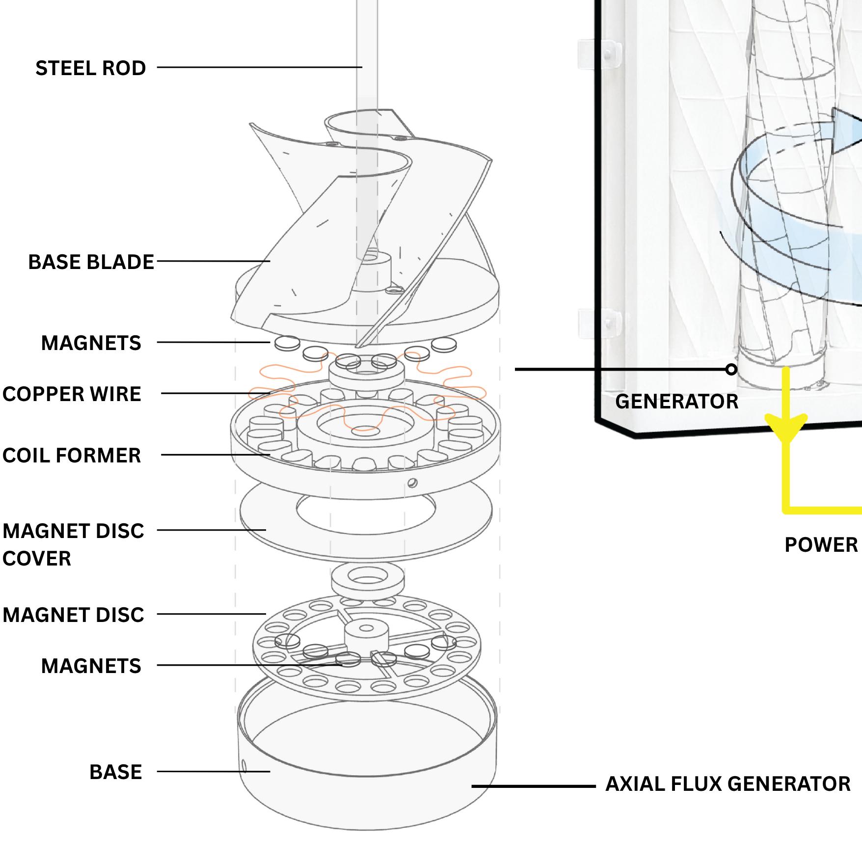
the Generator uses the “twisted serpent” method along with Neodymum/ rare earth magnets on the base of the first blade and below the twisted serpent.
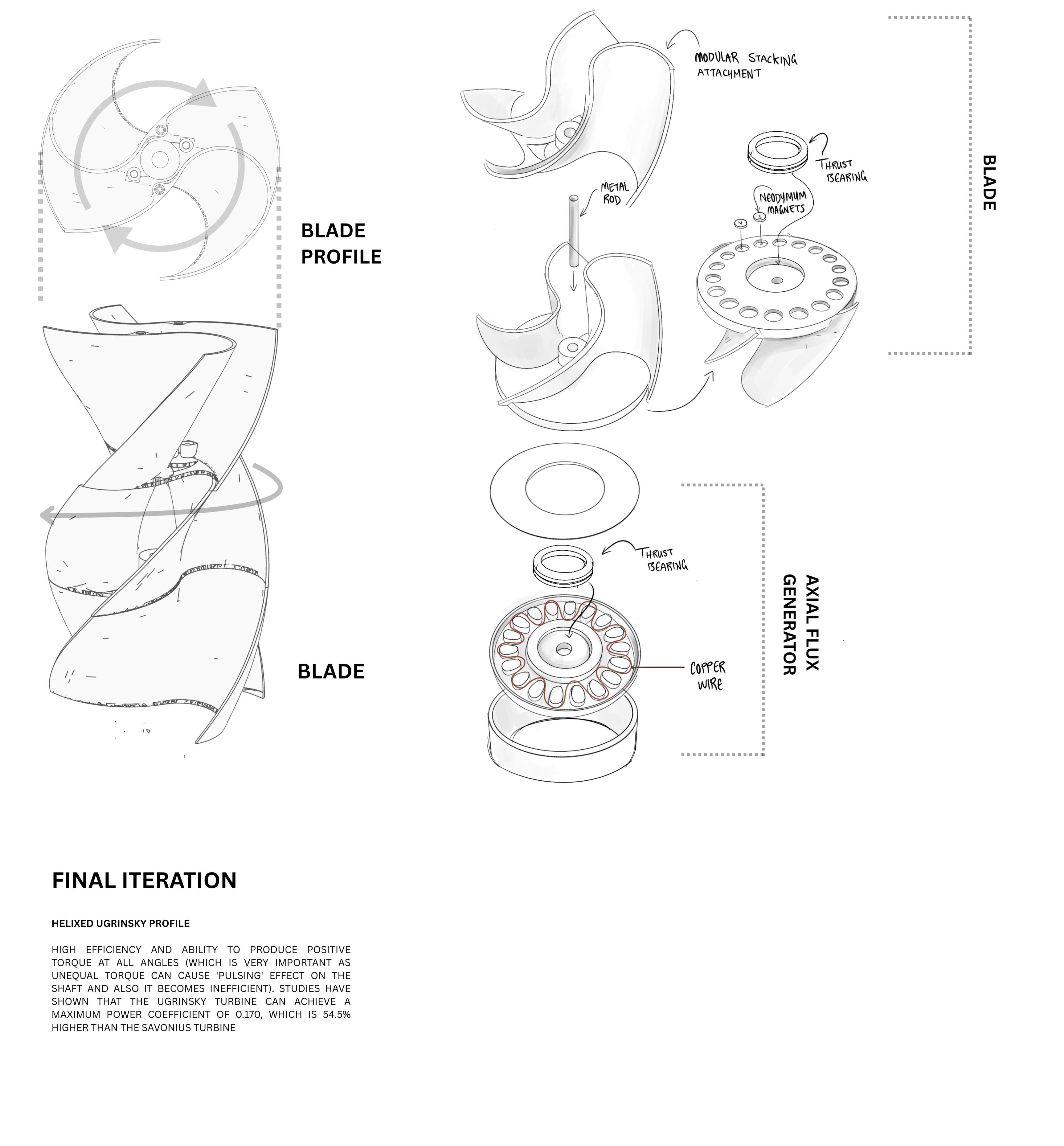
The generator uses magnets to generate a magnetic field which creates electricity in a coil. The helical or serpentine coil pattern utilizes the specific effect generated from the relative movement of magnets with the coil.
The design of the serpentine coil in a generator is such that the segments of wire are positioned to cut through a magnetic field in a generator, and a current is generated.

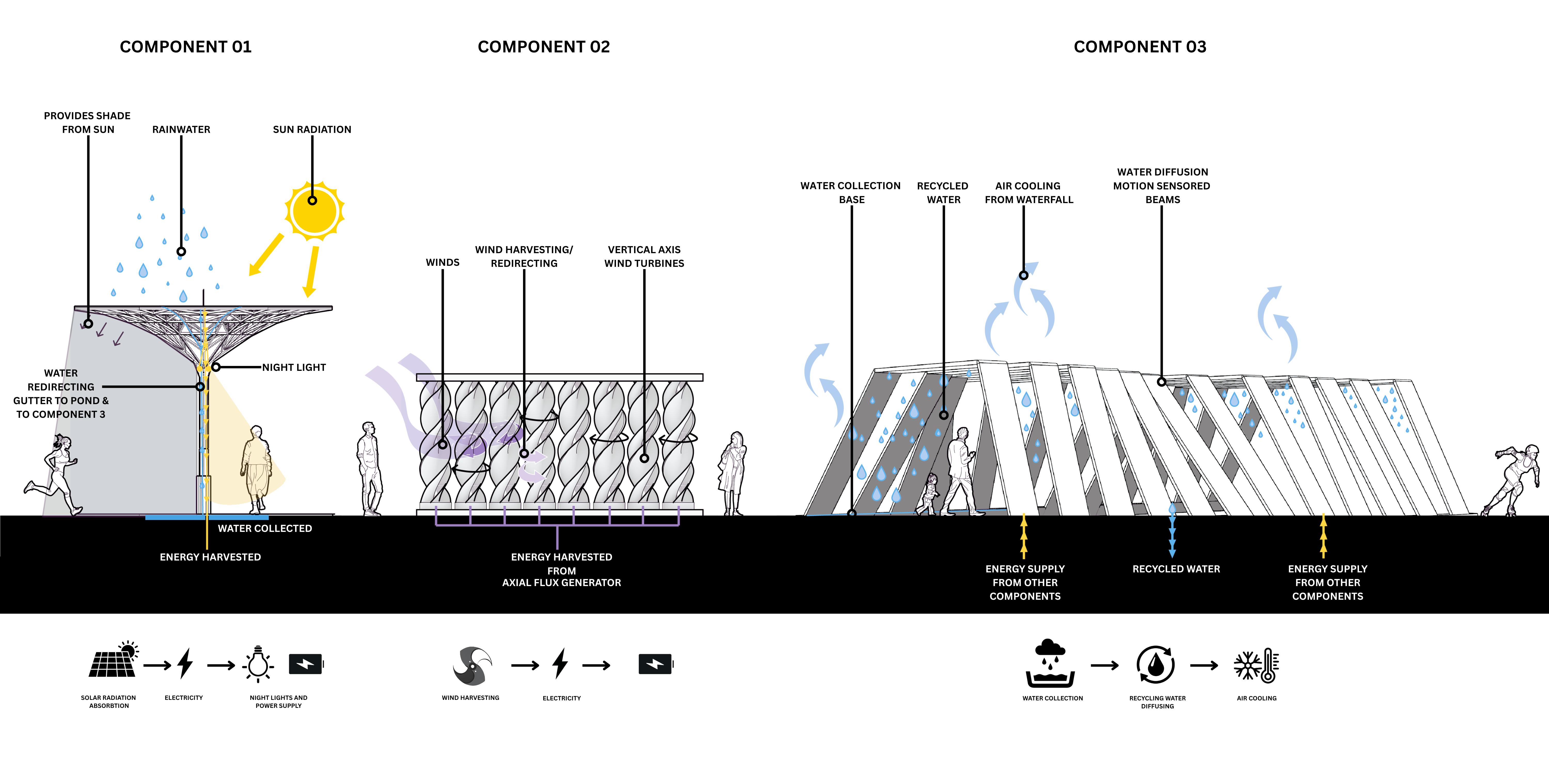
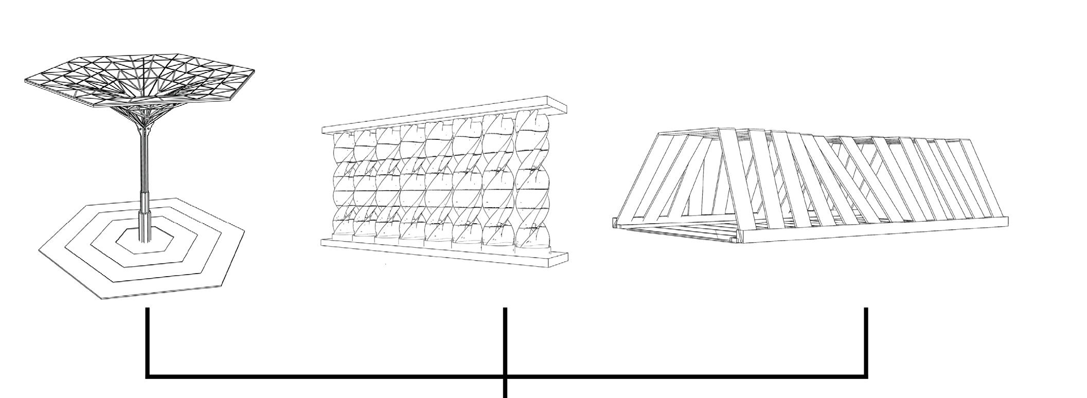
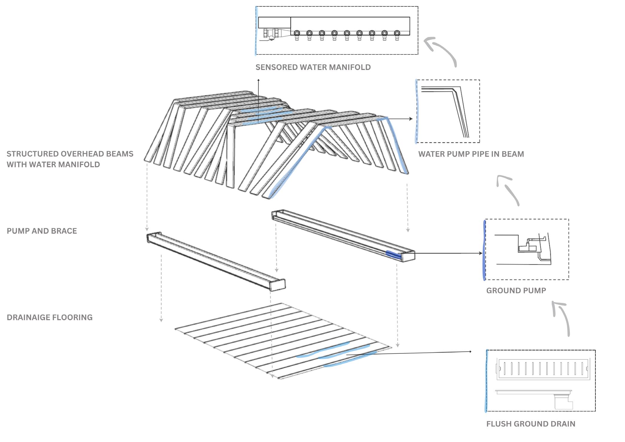
COMPONENT 01
02
COMPONENT 03