

2
A New Beginning
Master of Architecture Tectonics is a new program at the Faculty of Architecture at CEPT University. It is founded on the promise of developing competencies in architectural detailing and expression. The curriculum is focused on creating a community of fellow students and tutors who can examine, envision, and resolve a building’s architecture.
The MAT Foundation studio is a balancing act of four essentials of architectural tectonics. First, it teaches students how to make using analogy and digital workshop tools. The emphasis here is on tool handling, optimal posture while working, and the concentration required for general focus and safety. Second, it trains students to visualize structural stresses through modelling experiments. Students can express a detail based on structure and material properties. Third, it fosters agility in surveying available market items and products to employ them in detail or as a building element. Fourth, it prepares to discern between different sorts of drawings and create an appropriate drawing set to communicate an idea.
While grounded in the pedagogy around making as a basis, the studio never loses sight to be one of the prime movers of the future of architectural tectonics concerning India. An elaborate discussion on developing building language and aesthetics out of the coming together of industrial and natural material were taken at length to respond to some of our future environmental crises. In this sense, the foundation program is groundwork, reflexive yet with an eye set on the future for our students to lead with ideas when the time is right. We are very well answerable to a realistic present as much as to an imaginary future.
I acknowledge and express my deep gratitude to the students for having shown fortitude and taken a leap into the relentless demands of the foundation program. I am also thankful to my fellow teaching team Neel, Hemanshu, and Divya, for having supported me thoroughly and professionally during a tough academic time. We cannot fail in the beginning since we have failed so many times in the past. The studio remains incomplete without all of them. I wish to particularly thank Neel for having supported me in the studio throughout the last four years in a sustained way. I wish to thank CEPT workshop technicians Yatin bhai, Chirag bhai, Chhagan bhai and Amar bhai for training the students in the workshop. Maharshi bhai from FabLab ensured that the students learn 3D printing and laser cutting. Many thanks to him for his continuous support with modern tools. The studio also got immense support from Anjali Yagnik (Dean, Faculty of Architecture) in its inception, and colleagues of the Faculty of Architecture.
This booklet is inception to build a tradition of a compilation of studio work before the commencement of the CEPT exhibition. I am thankful to the entire student team to have made this possible.
Sankalpa
03 December, 2022
3
Foreword


4
Acknowledgement
The inception of MAT has been an exciting start of a journey towards a discrete vision in architectural practice that adds value through making, detailing, and meaning. The MAT Foundation studio successfully prompted us to reflect that a lot is yet to be explored, experienced, and experimented with. The studio inculcated knowledge in various areas allowing us to seek, analyse and reflect.
We thank Prof. Sankalpa and Neel Jain for opening our minds to a broader spectrum of skills and learnings. Our teaching associates, Hemanshu Dodiya, and Divya Solanki contributed significantly in adding value to the discussions and coordinating the studio. The studio framework helped us maneuver our thoughts into results through well-structured exercises and discussions. It was ensured that we became well versed with the workshop and sharpen our skills to understand the larger possibilities of making in Architecture. This inversion from making to drawing has made a difference in how we think now. We are grateful to Amar Kori, Chhagan Mahajan, Chirag Gajjar, Yatin Mistry, and the entire workshop team for their patience and guidance while training us at the workshop. Maharshi Solanki and Manish Patani guided us through the FAB-Lab and helped us explore digital fabrication technology.
During each exercise, the inputs from external mentors were insightful and needed at those crucial stages. We thank Anuj Anjaria, B.L. Manjunath and Shamik Desai for their valuable insights on mechanisms, building services, and structural systems.
Dinesh Sharma’s inputs on Fenestrations and Bhairav Patel and Aditya Patel on structural systems during midsemester reviews were valuable and thought-provoking.
We also thank our reviewers Mitul Desai, Pratik Soni, Saleem Bhatri, Saptak Patel, Sudhir Reddy, Smit Vyas, Surya Kakani, Vijay Arya and V. R. Shah for their valuable time and inputs on each of our projects. The conversations were interesting and provided a fresher perspective for thinking about a way forward in the program. Post-jury interactions with Bhavin Shukla and Kireet Patel opened avenues for discussions on varied topics. We thank you for initiating these valuable discussions.
Lastly, we would like to take this opportunity to thank every student who participates in the MAT Program. We all have been growing together through failure and success. Each of us is one of a kind and adds value and meaning to the journey ahead. We would continue to move forward with positivity and enthusiasm.
5
Khushi Daxini on behalf of MAT 2022 batch

6
Introduction
Course Description
The foundation studio aimed to set up a disciplinary impetus for the program with considerable emphasis on the method of design and making. The tectonic spatial form we see today is an expressive outcome of manipulating the geometrical logic, material,constructional, and structural ingenuities. The studio thus built the foundation of tectonics by ensuring students engage systematically in methods of investigation, derivation, and evaluation of form.
Four key considerations were accounted for while dealing with tectonics, namely:
1. Expression of detail as the articulation of structural forces
2. Expression of detail as the articulation of material and construction
3. Expression of the program as an articulation of detail
4. Expressive dimension of detail as expressed through prototypes, drawings, and models.
Coursework
The studio initiated familiarising students with the workshop, and building their ability to employ the various analogue and digital tools to produce specific building products. The developed skills were utilised through following exercises:
1. To make a mechanically controlled fenestration unit. The unit was aimed to be expandable, professionally deployable and technically innovative.
2. The second part dealt with the understanding of structural forces and their articulation in form. This is induced through active physical modelling by students using humble materials which mimic the properties of realworld construction materials. A spanning system was devised, tested and revised, to achieve an informed form.
3. The third and final part dealt with the consolidation of the above acquired skills, their resolution and their layering with a given design challenge. The skills were tested through three emerging typologies in a highrise, keeping in mind the future of resource crunch, land shortages and sustainability.
7
Making
Select one of the types of motion with material for the panel and the characteristics of the panel you wish to explore and attempt all the parts of the task given below.

Task
Design the climate control devices. Considering the dimension of frame to be 460 x 460mm.
Part A: To design a mechanism for the climate control device in a way that it can be operated through a mechanical input. Input force cannot directly be applied to the panel.

Part B: To design and make the panel for your climate control device. Preferably use more than one panel.
Part C: Do a market survey of hardware and fasteners that you would require in order to work out parts A, B and D. Make a matrix of those parts including detailed specifications and costs.
Part D: Design a locking system and a handle for the panel.

Learning outcome:
1. To detail out elements in two materials for a specific given function.
2. To identify and appropriately apply materials for a given task.
3. To design a mechanism to induce a type of selected motion in an opening. (4 weeks)
8 1.1
1.2
Opening assembly drawings


Create an assembly document for individual student’s fenestration in the sequence described:


1. A brief note of around 300 words describing each student’s object, its motion, materials, key highlights, and spaces where it can be used.

Modelling
Material:
Rigid Material: Board of max. dimensions 120 mm long, 20 mm wide, and 1 mm thick.

Flexible Material: Thin Printing Paper of max. dimensions 100 mm long, 100 mm wide, and lesser than 80 gsm,Flexible thread, thin transparent OHP sheet, pins, rubber-based adhesives
Task:
Students are required to pick a pair of end conditions from the options, and construct them1000 mm apart. Make a 1000 mm x 100 mm piece of OHP sheet and span it between the end conditions. The OHP should be broken into 3 or 5, or 7 and shall be placed in a horizontal plane. Stabilise this OHP sheet using the assigned materials.
While stabilising follow the following conditions: In stable conditions, the OHP sheet should not deflect more than 5 mm at the center under a 3kg uniform load over the entire spanning system. Material sizes should not exceed the specifications given. All connections have to be pin connections. Threads should be fixed at all connections and cannot slide. Distance between two parallel members should be 10 mm or more. Adhesives can only be used to connect your members at end conditions.
Tests:
The system should not deflect more than 5mm under uniform loading of 3 kg. The system should not break under 30 times its own self-weight or 10 kg load.
Learning Outcomes:
1. To derive a structural system that is able to resolve the intended load.
2. To physically realise the resolution of forces.
3. To recognise and articulate forces while addressing direction and magnitude.
4. To develop systems of joinery based on the behaviour of forces and mechanism of load transfer.

5. To develop modules that can repeat to form stable and complex assemblies. (3 weeks)

10 2.1
Identify materials for the spanning system and make a model at the end condition with the module next to it at the 1:5 scale.


(2 week)

11 2.2 Detailing and referencing
Input lecture and workshops
Mechanism, Gears and Systems : Prof.Anuj Anjaria Building services and application : Prof. Shramik Desai
Technicians guiding students
Metal Workshop : Amar Kori, Chaggan Mahajan

Wood Workshop : Chirag Gajjar, Yatin Mistry


Fablab Assistance : Maharshi Solanki, Manish Patani

12


13 Studio
M.A.T_Work
1. M.A.T Work becomes an attractive opportunity to access technology and equipment that an individual feels is essential and beneficial for one’s work but comes from a collaborative investment.
2. Workspace has a singular aim, to enable making accessible. These spaces are essentially open workshops that provide tools, spaces and even the know-how for individuals to create with. It aims to encourage a maker community where individuals with different interests and curiosities may come together to experiment, design and build, subsequently increasing the opportunities for creative problem solving and collaboration.
3. The spaces not only have access to equipment but also engage with other similarly motivated individuals and further diversifies collaboration opportunities.
Operation:
1. The makers can rent spaces on a weekly basis or quarterly basis.
2. Visitors can access public spaces freely, whereas studios only by invitation.
Design Objectives:
1. Function; allowing ease of making
2. Collaborate; spaces promoting creative collaborations, encourage involvement and interaction
3. Educate; space for individuals to learn from others and grow
4. Work and innovate; makers can customise their space for the nature of work
M.A.T_Learn
An individualised child-centric approach focused on creating a holistic upbringing of the child. A learning methodology that is satisfied through experiential learning by exploration and curiosity.
1. While the majoritarian view sees the learning spaces as a classroom, the new philosophy challenges the core pedagogical space and demands a new approach.
2. The foundation is seeking an architectural design where this pedagogical approach can be classified to rethink and reimagine school design beyond the perception of the typical classroom design.
3. It calls for an activity-based, hands-on learning school design based on this new learning philosophy. The complex understanding of children’s development and learning spaces can be brought into tangible architectural solutions.
Design objectives:
1. Design Flexibility; providing individual children to perform activities in their own way
2. Innovation; the design shall be challenging and innovative
3. Multifunctional spaces; able to carry out multiple functions efficiently.
M.A.T_Play
1. Sport centres are modern facilities which have to function extremely precisely and efficiently. In the Sports Centre, the inside and outside spaces are closely interlocked, creating harmony. As the exterior offers a place for the city to engage with along with the façade, the interior balances people’s emotions.
Design Objectives:
1. Inspiring and Integrating: To promote and encourage sports culture in the city.
2. Adaptability: to meet demands for flexible and differentiated sports facilities.
3. Efficient: Adhering to the international standards.
4. Educate: Space for individuals to learn from others and groW
14


15


M.A.T_WorkM.A.T_Work
M.A.T_Learn M.A.T_Play
02. Tessera
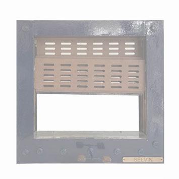
Rasika Lohar I Khushi Daxini
Selvin Varghese I Diksha Garg
05. Work links Hardik Arora
Interplay Manasvi Patil I Amrita Das
Hetansh Patel I Prateek Bansal
Vrushali Mali I Nishiki Varma
Mudit Tikmani I Miloni Patel 18 46 70 92 118 138 164 188 214 238 264
Content Foreword Acknowledgement
Introduction 01. Poly
06.
07. Vertical grounds Devashree Choudhari I Saurabh Narsikar 03. Four Gables
Harshal Kalantre I Hitprakash Mohanty 08. The Lacuna Alfiya Shaikh I Jyoti Mali 09. Learn High Aswin Sreekumar I Suriya Kumar 04. Built x autonomy
10. Tripple-Ripple
11. Frag-Play


The extensive 18 week Foundatio Studio did exactly what it intended to, it gave me a crisp introduction to what’s in store for this journey of architectural tectonics.
The studio followed a reverse pedagogy wherein we made to scale models right from the beginning and only produced the shop drawings once the final prototype was made. The idea was to better our understanding of materials and mechanisms through direct stimuli to our senses and get a more profound sense of “making.”
While the routes taken may have left me questioning the conventional methods of design, the uncertainty of a new process gave me an entirely new set of tools to work with, helped me build a stronger never die attitude and provided fresh avenues to interrogate.

At the beginning of the journey, one had an obvious question of “what” about the journey but the gradual process of taking one from an atomic to molecular stage has led one to question the “why” of it through critical understanding of the subject, in turn triggering a thought of its element and compound. The studio begun with a pragmatic approach of understanding mechanisms at a micro level and designing one at the node of functionality and aesthetics which later transformed into designing a spatial entity incorporated with the understanding of mechanisms done initially. This studio has induced a culture among us to look at any object’s design and functioning with a conscious effort of understanding it and knowing the purpose of its existence.
19
Mudit Tikmani Miloni Patel
PAT22206 PAT22197
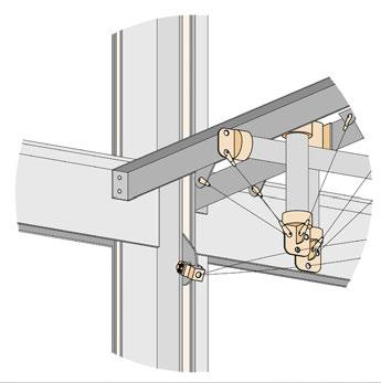
ASSEMBLY:
Star Link is a climate control device that functions on a vertical pivot motion. The primary materials used are timber and mild steel (MS). The device combines a system to links to that of a mechanical system which enables movement without any direct input force.
ABOUT TOOLS AND FINISHES
Timber: Automatic Saw Router Hammer Chisel Band Saw Sanding Machine Mitre Saw Junior Saw File
Mild Steel (MS):
Cutting Machine Drilling Machine Sheet cutting Grinding Machine Buffing Machine Clamps Welding Spot Welding Metal Chisel Hammer Punch Right Angle Pliers
Drilling Machine Impact Drill Wood Marker Screw Driver L Angle Adhesive Acrylic Spray Paint (Black)
Stain (Blue) Base Coat Top Coat
PARTS LIBRARY
Angle Bracket x 8 75mmx75mm Ball Bearing x 1 19mm dia., 6mm bore
Bevel Gear x 1 OD.: 43mm ID.: 6mm Teeth: 16; Right-Angle
Bevel Gear x 1 OD.: 65mm ID.: 6mm Teeth: 32; RightAngle
Threaded Rod x 1ft. 6mm
Double Screw x 32 25mm; 4mm dia.
Nut x 8 6mm bore
Washer x 4 6mm bore
Screw x 4 19mm; 4mm dia.
Nut- Bolt x 8 25mm; 4mm dia.
Sleeve x 4 19mm; 9mm bore
Nut- Bolt x 5 12mm; 3mm dia.
D- Nut x 1 6mm bore
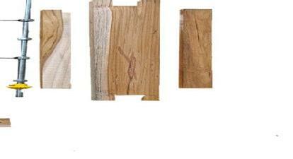
MATERIALS
All dimensions in mm.
90 90 90 90
x 75 x
15 15 30 30 x-15
20 y-80
2x+75 y 20
30 20 20 7 13 50
1. Assemble primary timber members.
172 20 50 45 25
210
335
12 12 35 85 85 85
210
335
172 20 50 45 25
Timber: X= 175; upto 350 Y= 400; upto 900 85 45 45
Mild Steel (MS): Acrylic: 85 45 45
2mm thick perforated sheet.

2mm thick solid sheet.
12 12 35 85 85 85
3mm thick clear sheet.
4. Integration of MS components.
20 STAR LINK
members.
2. Use L angles to fix members in postition.


3. Gear box assembly:
x 2

components.
5. Assemble the shutters and fixing of shutters onto the frame.
6. Final, closed condition.
21
fenestration by Mudit Tikmani

22
The plant-based turquoise stain can remind one of lights or the pol houses of Ahmedabad city
Linkages are connected to the shutters via clamps which provide the axis for pivot.

Perforated MS works well as the primary curtain wall element.


System of bevel gears connected to links.
of the northern city to the other.
Final, open condition. Opens upto 45 degrees.
23
fenestration by Mudit Tikmani
ABOUT

Phalanges is a climate control device that functions on a horizontal hinged motion. The primary materials used are wood and acrylic. The concept of the design was to imitate the movement of fingers which happens because of the hinge joints between two bones enabling the finger to move upward and downward.
The mechanical system of the device comprises of a pully connected with the worm drive. When the string of the pully is pulled it enables the worm drive to rotate enabling the cam follower mechanism to get into action because of which the fingers open and close.


The device is made with a combination of wood and acrylic. The expression of the window is fragile and graceful at the same time due to the used of acrylic. Also, the louvers made in transparent acrylic allows one to see the skeleton of the panel and provides a well-lit space even in the closed condition.
TOOLS
Automatic Saw Router Hammer Chisel Band Saw Sanding Machine Mitre Saw
PARTS LIBRARY
Drilling Machine Impact Drill Wood Marker Screw Driver L Angle Grinding Machine Lase cutting machine File
1. Assemble primary timber memebers of the frame.


Detail A : Step 1
3A. Assembly of the main members.
2. Gear box assembly.
4. Fixing the louvers on the main members.
5. Close condition of
24
MATERIALS
Screw Screw Nut
bolt
F
- F
-
Timber : Acrylic : PHALANGES Thread Rod
Nut boltNut boltNut
M -
pinM
pinM
F pin Pully Bearing Worm Wheel Washer L - Angle Worm
Detail A


3. Assembly of the main memebers with the cam follower system.


Detail A : Step 2


3B. Assembly of the main members with the cam follower mechanism.


Front view
Top view
the window. 6. Open condition of the window.
Side view
25
fenestration by Miloni Patel
Close

Semi-Open

Detail showing the connection between the cam follower mechanism and the arm of the screen with multiple hinge joints.

Detail showing the connection between the two separate arms of the screen by a serpentine element which allows the movement of both the memebers of screen in a synchronized manner.


26
Open
Detail showing the joinery of the transparent acrylic louvers with the arms of the screen. Notches in the arms hold the lovers in place which is further bolted using L-clamps. for stability.


Detail of junction of two hinge joints between: 1) two arms and 2) arms and serpentine members.


27
fenestration by Miloni Patel
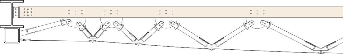
SPANNING 01:


The spanning system is conceptualised to integrate idea of modular units to that of tensigrity to derive a system which provides beam like solutions for large spanning area.


Module 01 consisting of 3 arms at set angles produced by “lost wax casting.” C clamp composed of 5mm plates is fixed to the module using plates in U profile.
Module 02 consisting of 3 arms at set angles produced by “lost wax casting.” Clamp supported the tension cable is fixed to the bottom of the module.

28
150x150x300mm C clamp composed of 5mm MS plate and anchored to the 38mm OD dia. rod using a 40mm ID dia. sleeve.


Turn buckle anchored to the bottom of the I-beam and used to keep the cables in tension.

150x150x300mm C clamp composed of 5mm MS plate and anchored to I-beam with brackets and 12mm bolts.


29
spanning by Mudit Tikmani
Top View
End Condition and Module 01.
Module 02 detail and tension cable.
Isometric View
The exercise focused on deriving a structural system that is able to span for 10 meters. Initially dummy materials like paper and pins were used to design modules to span horizontally while understanding the behaviour of forces acting on it. Further, the spanning had to be resolved for it to materialise in reality.


The idea here was to create a spanning system that has a delicate demeanour but takes load in actuality. To do so, the spanning system was created with bundled tubes running horizontally which was imagined to take certain load above it.

30
Weld SPANNING 02:
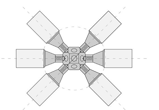
Mero Joint Detail


31
Steel tubular section Cover sleeve Rod anchor Locking ring Gusset plate Ring stiffner
Final model - Elevation
spanning by Miloni Patel
Final model - Isometric view
Location : Sabarmati Riverfront, Ahmedabad
Site Area : 6375 SQM.
Typology : Workspaces | MAT Work


Poly which translates to “many” is built on the idea of bundled columns and split core system. Taking an unconvential route for both, structural and functional systems of a multi-storey structure, the intention is to blur the lines between primary and secondary spaces.

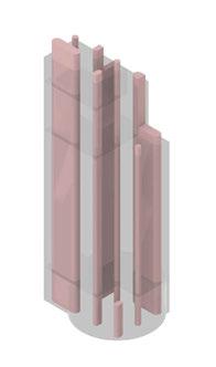
MASSING IN-PROCESS:
Singular mass and core.
Singular mass and split cores to enable greater internal permeability.


Split mass to increase exposed surface area to capture more views and sun.
Cores massing as imagined with typical functions.
Structure restrictricted to the core perphery to integrate functional to structural systems.

32
POLY
CORES: ZONING:
Vertical Circulation: Staircases


Service Cores
Wet Areas
Admin. an Vertical Circulation: Lifts
Service cores are distributed across the floor plate to better integrate them with the primary spaces.

Washroom/ Kitchen Core at the south-west can modulated on each floor as per requirement.


DEVELOPING AN EXPRESSION:
Admin. and Services
Public and Community Spaces Workshops Studio/ Lecture Halls/ Co-Working Spaces
Spaces with greater dead load stacked towards the bottom.
Fixed/Regular footfall areas placed towards the top.
System of bundled columns; 70 primary columns each of 150mm dia.

Columns wrapped around the critical core positioning to curtail south light.
16m tall circular podium defined by 150mm dia. columns.

Using metal curtain to act as primary external skin along with dry walls at certain locations to break monotony.

33
organization and planning_poly


34 4 WHEELERPARKING 2 WHEELERPARKING
STP
05 10M UNORGANISED SETTLEMENTS TOWARDS SABARMATI RIVER RIVERFRONT
Ground Floor Plan
AMPHITHEATRE ALIGHTING AREA ENTRY EXIT
SECURITY TRANSFORMER POND RETAIL SPACES 1. 2. 7. 4. 6. 3. 5. 7. 8. 9. 11. 12. 12. 12. 1. 4. 6. 10. VEHICULAR ACCESS EXHIBITION AREA
RIVERFRONT ROAD TOWARDS AIRPORT
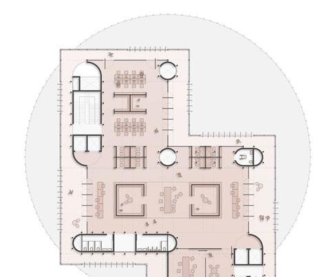


35 1. Staircase 2. Garbage Chute 3. HVAC Shaft 4. Fire Shaft 5. Electric and Server Shaft 6. Passenger Lift 7. Service Lift 8. Female Toilet 9. Male Toilet 10. Drinking Water 11. Accessible Toilet 12. Plumbing Shaft 13. Kitchen/ Pantry 14. Unisex Toilet 15. Storage LEGEND ground floor plan and typical floor plans_poly
Auditorium
Library Studios Lounge/ Day Care Centre Workshop
1. 2. 7. 4. 6. 3. 5. 7. 8.9. 11. 12. 12. 12. 1. 4. 6. 10. 1. 2. 7. 4. 6. 3. 5. 7. 8.9. 11. 12. 12. 12. 1. 4. 6. 10. 1. 2. 7. 4. 6. 3. 5. 7. 14.13. 11. 12. 12. 12. 1. 4. 6. 10. 1. 2. 7. 4. 6. 3. 5. 7. 8.9. 11. 12. 12. 12. 1. 4. 6. 10. 1. 2. 7. 4. 6. 3. 5. 7. 8.9. 11. 12. 12. 12. 1. 4. 6. 10. 15.
Top of overhead water tank.
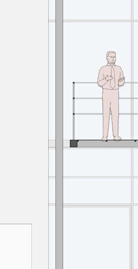
+128m +120m
End of habitable/Service areas. +72m
Double Height 03: +32m

Top


Double Height 02: +16m


36 BUILDING SECTION: B2 B1 G 01 02 03 04 05 06 07 08 09 10 11 12 13 14 15 16 17 18 19 20 21 22 23 24 T 0 8 16M
Level Basement Below
of podium. +/-00m Double Height 01: Ground
Decking Sheet below VDF flooring.


Spanning system across a 9m span supporting glulam members.

450mm deep cellular I-section.
Ring beam tieing the bundled columns together.
150mm dia. MS sections as the unit of bundled columns.
buidling section and structural system_poly


37
STRUCTURAL SYSTEM:


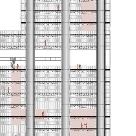
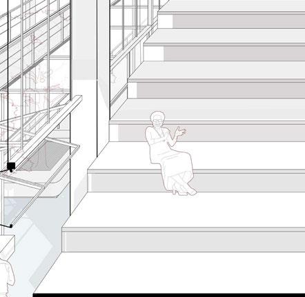
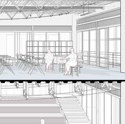
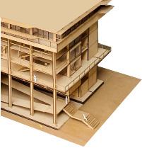
38 SECTIONAL PERSPECTIVE ACROSS FLOORS 12-14:
CAFE/ LOUNGE/ DAY CARE CENTRE


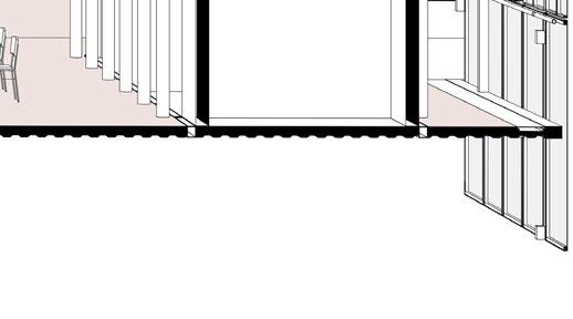


WORKSHOPS
STUDIO/ CO-WORKING SPACES


39
sectional perspective_poly
1. Fixing 50mm dia. MS section between two mullions as railing and adding C clamps along the I-beams.
Study Model


2. Assemblying the metal curtain by wrapping it around a frame made of 25x25mm MS box section and clamping with MS plates on all 4 sides.


3. Attaching the modular frame onto the I-sections with the help of the clamp.
4. Openable vertical pivot devices controlled through linkages. Infill made in same metal curatin. Final, open conditions.
40 FENESTRATION ASSEMBLY:
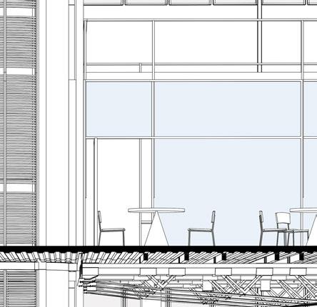
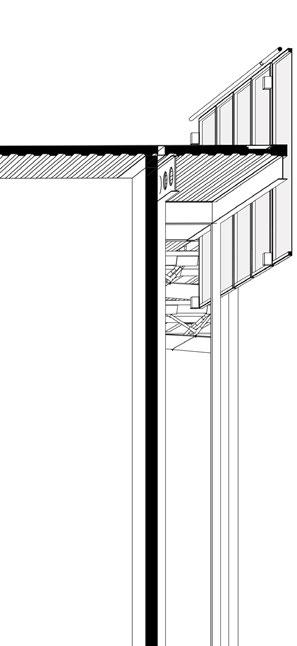
1. 100x110mm MS I-Section Mullions to mount the curatin wall.
2. 110x300mm MS I-Section on the periphery of each floor plate. 3. MS Floor Drain 4. Mezzanine Floor Parapet Composed Of 38x38mm MS Box Section. 5. 4mm Thk Metal Curtain wrapped over 38x38mm box section. 6. Mezzanine Floor 150x150mm MS Box Section. 7. 150x150mm MS Box Section Bundle Column Tie Member.


150mm Dia. Ms Section Bundle Column Member
13. 110x400mm MS I-Section Cellular beam as secondary spanning beam.


Opening system in vertical pivot motion. 15. 38mm dia. MS section between mullions as handrail.
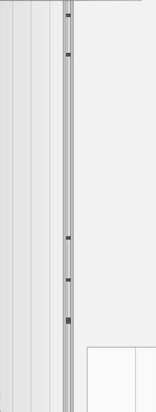
41 WALL SECTION: fenestration
assembly and wall section_poly
9. VDF Flooring 10. Decking Sheet 11. Aluminium Flashing 12. Spanning System
LEGEND 4. 12. 6. 13. 14. 5. 15. 3. 11. 2. 8. 10. 9. 1. 0 0.51M
8.
14.


42
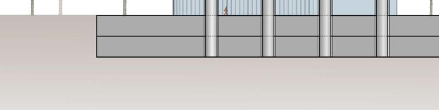
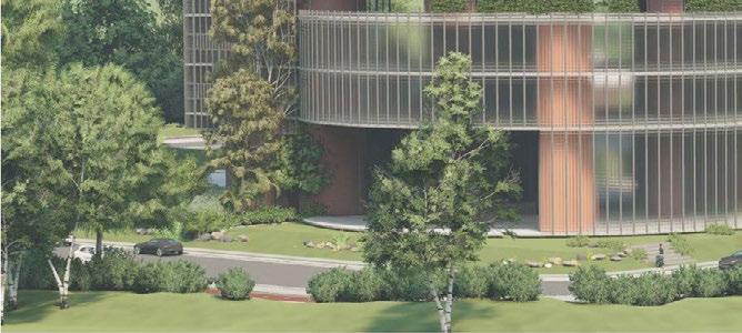
Exterior view as seen from north
north of the structure.
Workshop
Studios
Lounge/ Day Care Centre


Typical Space between the exterior and interior skin.


43
visualisation_poly
Process model expressing the verticality of the building.


Process model expressing the volumetric play in the building.
Process model showing the play of vertical service cores.
Modelling the fixed cores and structure composed of bundled columns and floor plates.


Fixing the facade panels on the structural skeleton and curtaining the podium with slender vertical facade mullions.
Facade panels placed completely on the whole building.
44
STUDY MODELS:


45 study models_poly

Writing a reflection for me is to look back at the learnings in terms of the journey and how far I’ve come through. A person isn’t static, and who am I right now is not as important unless we have the context of what I was before this studio. It has broadened my spectrum of questions whose answers are to be found. The studio has pushed my limits so much so that at this point, it feels content to have been survived through. The last 4 months really challenged me to realise my abilities as well as inabilities. These realisations were important so that it can be worked on with a positive attitude and enthusiasm. It was a journey of learnings, unlearnings, failures and success.

The Foundation Studio has boosted my sense of detailing. It has pushed me to get out of my comfort zone and explore myself to create something beyond my limits. The Process of making, fostering new technologies, critical thinking, failures, brainstorming, making mistakes, resolving, learning, translating ideas into details, the expression of forces, their articulation into spanning system, structural systems, materials, and details, all of it has encouraged me to learn from own mistakes and advance further based on the learnings.

47
PAT22167 PAT22278
Khushi Daxini Rasika Lohar
SWIVEL
Horizontal Pivot Window


Swivel is a Horizontal Pivot Window designed to simplify user experience by providing a single rotating handle for multiple horizontal pivot panels. The mechanism is based on connecting multiple panels with gears that are provided with motion through a single loop of timing belt on both sides of the window frame. The bevel gear setup at the base of the window frame change the direction of the motion, facilitating movement of the Timing belt.

48
Kit of Parts
01.
02.
03.
04.
05.
06.
07.
08.Timing
09.
10.
11.
12.
13.
14.
15.
LEGEND
MS Anchor for MDF Frame
Nut Bolts
MDF Frame for MS Panel
MDF Panel
L Angle
Acrylic Panel (MDF Substitute for visibility)
Gear
Belt
Ball Bearing
Washers
Bevel Gear
MS Rod for Bevel gear
MDF base panel
MS Panel
MDF Front frame
Align timing belt to the gear set in synchronization
Fix panels to the MS Anchors using nut bolts

Closed condition Open condition

49 fenestration
by Khushi Daxini
Assemble MDF Parts with interlocking system.Gear Assembly with MS Panel anchorsAssemble Bevel gear Assembly at the base
REPRISE
Vertical Sliding Shading Device

Reprise is a Vertically Sliding shading device designed in MDF and Bamboo as its primary material used for construction. This device translates rotational motion into linear motion. When the handle is rotated in anti-clockwise direction , the panel of opening moves upwards.


Tools Used
Bamboo saw Mallet Knife Hacksaw Planar Machine Sanding Machine Mitre Saw Junior Saw Right Angle
File Drilling Machine, Socket drill Chisel Hammer Wood marker Screw Driver Pliers Punch
Cutting Machine Laser cutting Machine Drilling Machine Sheet cutting Grinding Machine Buffing Machine Clamps Metal Chisel Hammer
1. Bottom Frame Assembly


2. Addition of Mechanism

Parts Library
Panel Assembly
3. Addition of Panel and Frame
50
Open Condition


51 fenestration
by Rasika Lohar 5. Frame Top Part Assembly
Closed Condition 4. Addition of Front and Back of Frame
The intention of this exersice was to understand the basics of forces, in terms of direction and magnitude. The learnings were taken forward to understand how pyramid as an accepted stable form can be incorporated into a force diagram to design a spanning system (10 m span). The process initially explored pyramid as surfaces and eventually was optimized into line diagram keeping in mind material utilization, joinery details and aesthetics.


This exersice also explored new means of technology for model making through 3D Printing.


52 SPANNING 1
Process Models
Final Model
1 2
3 4 5


10
Typical condition Detail 01 End condition detail 01
End condition Detail 02
7 6 8 1 3 LEGEND 01. Glulam member (120x180 mm) 02. MS Gusset Plate (5 mm thk.)

8 mm Dia Bolt 04. Hook for tension cable 05. MS Pipe (60.3 mm OD) 06. MS I section as beam
MS Box section 08. MS Plate for Glulam anchor (5 mm thk.)
MS Plate on Box section 10. Tension cable (8 mm thk.) Isometric View


Typical condition Detail 02
53
Elevation Plan
03.
07.
09.
spanning by Khushi
Daxini
The Spanning System exercise helped to understand the line diagram of forces and the translation of line diagram into a spanning system consisting of spanning members, as a stable form which was designed and explored using state of the art technologies such as 3D printers, which in this case helped to explore and convey material expression. The process also helped us understand the ways of material optimization, making and experimenting joinery details with respect to aesthetics and stability.

Process model of spanning system
Final model of spanning system


54 SPANNING 2
Plan of spanning system
Elevation of spanning system
1. 2 3 4 5 6 7 8
Spanning Assembly Drawing


1. 60 x 60 mm M.S angle
anchored In the precast member and M.S box section
2. 172 x 92 mm M.S box section that holds the precast spanning member

3. 450 mm depth M.S I section
4. 8 mm thk M.S base plate
5. 6mm thk gusset plate with Cylindrical y - end pin
6. 12mm dia tie rod in tension
7. 6 mm M.S plate anchored in precast member.
8. M.S rod end that holds 12mm tie rod tension member
3 4 5 6 7 7
Isometric view of assembled spanning system
2 2
1. 1.
8 8
Elevation of Spanning member
View of end condition and cable to spanning member detail
by Rasika Lohar
55 spanning
Inspire; inspire makers through design form and spaces, be an identity Function; allowing ease of making Collaborate; spaces promoting creative collaborations, encourage involvement and interaction.
Educate; space for individuals to learn from others and grow Work and innovate; makers can customise their space for the nature of work
LOCATION : SABARMATI RIVERFRONT, AHMEDABAD
SITE AREA : 6375 SQM. TYPOLOGY : WORKSHOPS


TESSERA
9m
1m 3m 0 Site Plan
Understanding site, context and movement
Understanding scale, orientation and built mass
Design Development
Seggregating core and program and developing the form to create sense of approach
Integrating ancillary activities as a linkage to primary activities and the service core.
12 m3 m9 m 7.5 m 9 m 7.5 m
Seggregating Work areas and Service core as a key to initiate design.


Re-orienting the service core block to allow sense of approach and accessibilty.
Integrating column-grid. Eccentric corridor provides varied spanned spaces, as an intention to divide primary and secondary spaces accordingly.


Integrating services, shear walls to understand the structural system wholistically.

Finalizing movement diagram with a focus on the importance of connecting transition space.

57 organization and planning_tessera
Concluding geometry, movement, spatial configuration and overall structural system. Form Development

58 Ground Floor Plan 01 02 03 04 10 11 12 01. Atrium 02. Wood Workshop 03. Administration 04. Machine Lab 05. Toilet (Male) 06. Toilet (Female) 07. Toilet for specially abled 08. AHU 09. Passenger Lobby 10. Foyer 11. Landscapes 12. Loading Unloading deck 1m 3m 0 9m 1m 3m 0 9m 0 m3m 9m 18m
Typical Floor Plan (Workshop + Studio )
8th Floor Plan ( Library + Archive )
Typical Floor Plan ( Discussion Rooms + Studio )


11th Floor Plan ( Cafeteria + Recreation )

59 organization and planning_tessera

60 Section Basement Ground Floor Podium 8th Floor 3rd Floor 11th Floor 22nd Floor
Terrace Lvl OHT Level
LIBRARY
CAFETERIA WORKSHOPS and STUDIOS
WORKSHOPS and STUDIOS
1m 3m 0 9m 0 m4.2 m 9m 18m
AUDITORIUM Atrium
Decking Sheet

Joists along 9m span to support MS Section
Spanning system adding structural stability in larger volumes
Castellated beams along corridor for ease of services
Shear Wall ( Passenger elevators )
Castellated beams along corridor for ease of services
RCC+I-section composite columns
Flooring 450 mm deep I-Sections
Structural System
61 building section and structural system_tessera

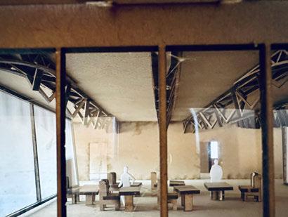
62

63 sectional perspective_tessera


64 Wall Section Detail at Floor Junction A 1 2 3 4 5 6 7 8 9 10 Perforated sheets composed for varied light and ventilation requirements of the space M S Framework For Facade exo-skeleton acting as a layer to modulate porosity 1. M S I section 450 MM Depth 2. M.S 100 X 100 MM Box Section 3.Perforated Metal sheet 4. Vertical cross bracing cables 5. Spandrel panel 6. Double glazed inner facade 7. Horizontal extrusion for upper unit 7. Vertical extrusion for upper unit 8. Horizontal pivot shading device 9. Precast spanning members 10. 172 x 92 MM Box section holding precast members B C D
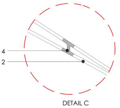
The IDEA
Detail showing integration of primary structure, spanning and glazing layer


B
Aluminium grating detail
A C D
Fenestration Details
65 fenestration and wall section_tessera
‘Porosity as a derivative of spatial Organization’
Process Models


66


67 process_tessera


68


69 model and renders_tessera
 F O U R G A B L E S
Understanding the significance of the process of creation and then realising the end product as a result of the process was the most important takeaway from this section of the program for me. Paying close attention to the origin of any detail and how it ultimately works in relation to the material and constructional approach used. In terms of course pedagogy, the studio allows students to investigate the structure of an idea and how to make it a reality by actually constructing it, accompanied by a seamless workshop making experience. This helped me acquire confidence in my ability to create, ultimately validating my concepts..
True learning in architecture can only be absorbed by intimating oneself with real material. That’s what I have understood from this part of the masters program. A rigorous process of visualisation as well as experiential structural systems both in digital and physical has widened my vision of looking into micro levels of architecture. Moreover, the intensity of the foundation program helped me stretch my limitations to it’s extremes and overcome them.


71
Harshal Kalantre
PAT22136
Hitprakash Mohanty
PAT22130
Vertical folding and rolling Window
The rolling and folding window is made out of Timber frame and MDF panels where the whole framing system is strengthen by tongue and groove joints. The window has a singular function of folding up and down which is controlled by the rotation in both direction of the knob below.The function run in simple concept of pulling and releasing.


72 ZIG-ZAG
Mechanical functioning of Window:


Outer frame parts are fixed in all grooves created

Parts Library:

Mechanism is fixed to the frame and its panel 5mm MDF panels are fixed in perpendicular to each other as shown in the above diagram


Timing Belt 40mm dia gear
Nut & bolt
Window opening motion images:
73
fenestration by Hitprakash Mohanty
60mm dia gear6mm threaded rod MS cleat


Construction timber
4mm folded gusset plate
2mm M.S. Plate 5mm thk. M.S. Plate
2mm thk. M.S. bend plate

8mm thk. tension cable
Detail A : Support Module
Detail B : End Condition
Cable Holder 6mm thk. M.S. Plate
Metal cable holder
3mm triangular MS plate is welded to maintain its form
4mm gusset plate to fix decking sheet 4mm gusset plate

50mm thk. const. timber
Detail D : Triangular plate


Detail C : Joinery

76 SPANNING SYSTEM:
This spanning system is a type of beam that can span up to 10-15m between beams or columns. This system, in particular, reacts differently to forces that come from above. As a result, while designing, a few factors were taken into account, such as the joinery of both the end conditions and the nature of the material, because different situations react differently to the forces applied to them. The majority of the spanning material in this system is flexible, which can be built of MS folded plates and is supported by additional stiff members to avoid torsion. A tension cable is supported beneath the system to prevent it from buckling or bending.
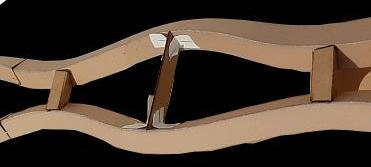


77
spanning by Hitprakash Mohanty
Model Images:
Process models:

78 SPANNING SYSTEM

79 spanning by Harshal Kalantre
LOCATION : SABARMATI RIVERFRONT, AHMEDABAD
SITE AREA : 6375 SQM.
TYPOLOGY : vWORKSHOP SPACES
Four Gables is a multi-use commercial high rise tower comprising of workshop spaces, studio spaces, a multi-floor library and an auditorium with a capacity of about 200 persons. The design was developed to create multi-level spaces establishing an internal visual connectivity between floors in a high rise building.

80
FOUR GABLES
The basic idea was to design the structural system of the high rise such that the activity could take up as much floor area as possible. By locating the service cores on the four corners, we free up floor space from columns and shear walls.

With the service circulation now oriented along the exterior face, the circulation areas in the centre are limited. Therby allowing more volumnar variation in spaces with the provision of double heights and mezzanines.
The buidling mass is also raised to allow barrier free user movement throughout the plinth
81
Diagrams & Models :
Conceptual
Service cores are placed on all four corners
Volumnar mass raised to provide public space
organization and planning_Four Gables
Volumetric recessions on west and south facade to optimise daylighting and thermal heating

82 BUILDING ORGANISATION
Workshop floor plan


83 organization and planning_Four Gables
Site Layout
11.
12.
Auditorium floor plan Legends: 1.Auditorium 2.Open air theatre 3.Electrical shaft 4.HVAC shaft 5.HVAC Shaft 6.Plumbing Shaft 7.Electrical shaft 8.Fire shaft 9. Workshop seating 10.Tool rack
Working Table
Workshop machinery

84 SECTION
Structural Layout Exploded View :Structural System
100mm RCC on 2mm decking sheet
Spanning system 1 & 2
Decking sheet to I-section (beam) joinery
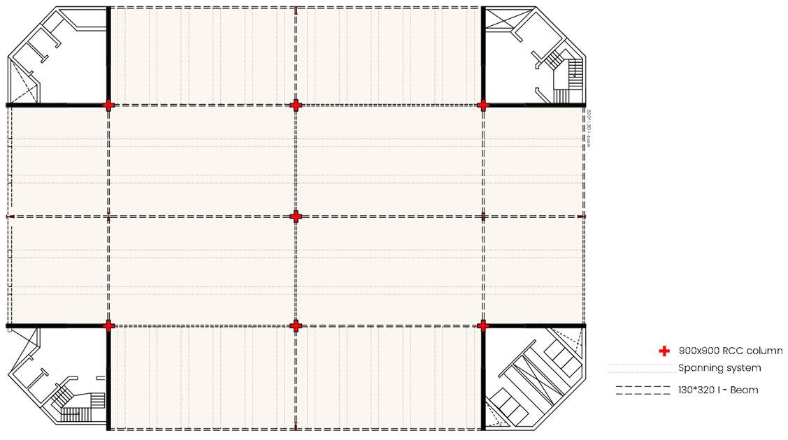
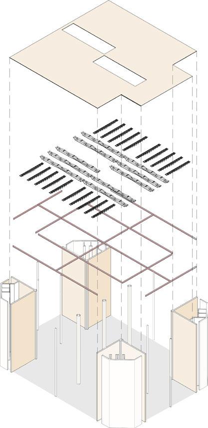

130*320mm I-section Beam
I-section(beam) to shear wall joinery


Four cores consisting L- shaped shear wall
I-section(beam) to H-Section column joinery
85
STRUCTURAL SYSTEM
Building section and structural system_Four Gables

86 SECTIONAL PERSPECTIVE

87 sectional perspective_Four Gables
50mm flooring 100mm RCC Slab on decking sheet
2mm decking sheet
Spanning system
300*300mm H - section column
60*60mm Box section framing 130*320mm I - section as beam
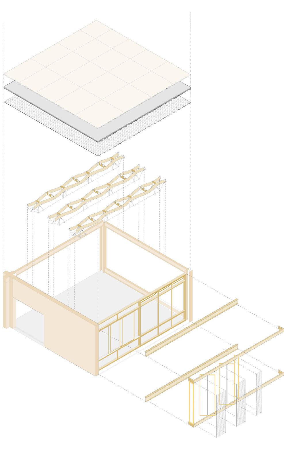
C- section as Support of vertical louver
Vertical louver with metal porforated panel
88 FENESTRATION DRAWINGS


89 fenestration and details_Four Gables
Handle Vertical Louver detail:
gear
MS Rod
box section Aluminium
thk. MS Plate
bearing
Fenestration model image: Fixed glass detail: Bevel
10mm
60x60mm
casing C-Shaped Aluminium frame Double glass 2mm
Ball
C-Section(Bottom) C-Section(Top) Ball bearing

90


91 physical model_Four Gables

My approach towards an architectural intervention has always been through understanding of a mass, where detailing somehow was a recurrent thought to the overall built. Through this semester, I developed an outlook towards detailing as an integral part of a whole. I have realised how even an opening design is tied to the expression on a city wide scale.

The studio began with the fundamental question of starting a design from a part rather than the complete and progressed to the integration of details in the final exercise. The concept centered around creating a narrative about the relationship between spatial experience and the processes that generate expression. As a result, the overwhelming process of employing tools in the workshop and understanding dynamics leading to design in a construction system was fulfilling. Working with scales that are rarely used, such as 1:1, 1:10, and 1:50, as well as having hands-on experience with manufacturing, helped build a grasp of materials and their behaviour, as well as the art of construction.

93
Selvin Varghese
Diksha Garg
PAT22312
PAT22100
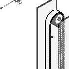
LATTICE
vertical sliding opening
‘The lattice’ is envisioned as modular based system for vertical sliding opening. The system devised tries to achieve opening using rack and pinion system and transferring the motion through a pulley mechanism into a timer belt attached to spur gear and the panel.

The distance travelled by the rack is equally proportionate to the movement of panel upwards.

MECHANICAL
94
SYSTEM_COMPONENTS
Rack Timing belt Acrylic washer Acrylic washer
PROTOTYPE_CLOSED AND OPEN CONDITION
Spur gear Ball bearing M.S rod
Roller wheel


95 W-110 50 W-135 65 W 65 W-110 80 11 H H-135 55 65 1. M.S. main frame components + assembly_parts 3. Side
assembly 5. Panel assembly_parts 6. Closed and open
assembly 2. M.S.
components + assembly_ welded 4. Bottom
frame
condition_final
main frame
frame assembly
fenestration by Selvin Varghese

96

97 fenestration by Diksha Garg
A structural system is derived that is able to resolve the intended load, using 120mm long, 20mm wide and 1mm thick board, 80 gsm paper and flexible thread. Support members were used under the following conditions: rigidity 60%, flexibility 10% and threads 30%. The spanning uses Glulam top-chord connected to the structural member and the spanning members are composite of glulam and M.S members adhering to compressive and tensile stresses. Steel cables are further used for further tensioning of the members .


B
1. 2. 3. 4. 5. 6. 7. 8. 9. 10.
150 x 150 Glulam spanning member
10mm thk MS plate
150 x 150 Glulam
10mm thk MS Connector
10mm thk MS strut
5mm thk Gusset Plate
5mm thk Gusset Plate with hook for tension cable
8mm thk tension cable
8mm dia bolt
10mm dia Bolt
98 SPANNING 1
A
Detail at ‘A’


Detail at ‘B’
7 3
1 2 3 4 5

9 9 2 4 5
3 8
6 10 8 spanning by Selvin Varghese
99
Detail at ‘C’

100 SPANNING 2

101 spanning by Diksha Garg
Our spaces’ needs and requirements are always evolving. Today’s urban environments demand ongoing expansion and change. Buildings are often created with the goal of serving specific roles and user groups and not undergoing major modification over its lifetime.
Functions may change over time, but form is what remains.
SITE PLAN

Way to Basement
10m Wide Road Loading and Unloading Bay Parking
Entrance 0 20
102 Built x autonomy
Urban Plaza Exhibition Area Play Area
Workspaces
Socio-interaction spaces
Studios
Urban farm Workshops Multifunctional hall Library Lecture hall Auditorium Offices
Retail and urban plaza
CLIMATE CONSIDERATIONS
103 organization and planning_built x autonomy
Site Program Distribution Program Distribution
and roof open spaces BUILDING ORGANIZATION
Existing
Mass on Site Elevating the ground form Ground
SYSTEM Permeable floor plate to allow cross ventilation Provision of informal double height volumes along north and east and service core along south to prevent heat gain Permeable floor plate to allow cross ventilation Provision of informal double height volumes along north and east and service core along south to prevent heat gain
STRUCTURAL
Inner and outer columns Service CoreCross Ventilation Double height volumes across northern facade
Break
Workshop zone 1 Workshop zone 2
Staff lockers and storage
Service storage/ Multi purpose room
Common Workspace
TYPICAL WORKSHOP PLAN
seen below
TYPICAL STUDIO PLAN


104
out space Workshop
1 23 4 5 6 7 10 9 11 9 12 13 14 8 1 1 23 4 5 6 7 10 9 11 9 12 13 14 8 1 10 0 10 0


105 organization and planning_built x autonomy 1. 2. 3. 4. 5. 6. 7. 8. 9. 10. 11. 12. 13. 14. Staircase HVAC Indoor Unit HVAC Shaft Dust Collection Area
Break out space Planter box seen below
Storage/
Ramp Up 1 23 4 5 6 7 10 9 11 9 12 13 14 8 1
PLAN Studio 1 Studio 2 STUDIO/
PLAN 1 23 4 5 6 7 10 9 11 9 12 13 14 8 1 10 0 10 0
Service Lift Female Toilet Male Toilet Plumbing Shaft Passenger Lift Drinking Water Service Storage Garbage Chute Fire Shaft Electric and Server Shaft
Discussion Area
Control Room Green Room
AUDITORIUM
LECTURE ROOM
Urban farm Workshop and studios Library Auditorium and lecture hall Reception

SECTION
1 2
7 8 8 9
6
3 4 5
10
11 12
1.150 x 200 Glulam spanning member 2.550 x 550 ISMB and RCC composite column 3. 130 mm thk. steel deck slab and VDF flooring 4.450 x 220 I section beam 5.65 mm thk. FRP grated flooring 6.Vertical sliding folding partitions

7. 250 x 110 M.S. C-Channel 8.75 x 75 SHS column 9.Vertical hinge opening 10.Horizontal pivot opening 11. U-PVC louvers 12.Chicken mesh
building section and structural system_built
107
x autonomy STRUCTURAL SYSTEM


108 SECTIONAL PERSPECTIVE


109 sectional perspective_built x autonomy
110 FENESTRATION DRAWINGS 2 1 A D B C 1 detail at ‘A’ detail at ‘B’ detail at ‘C’ detail at ‘D’ 2 1 2 5 6 111 1 12 14 4 6 8 9 3 3 10 7 1 3 1.75 x 75 SHS Column 2.40 x 40 SHS 3.12 mm MS Tie rod 4.Clevis and Yoke 5.MS angle runner 6. Steel sheet panel 7. MS angle cleat 8. Vertical panel joint 9. Horizontal panel joint 10. Turnbuckle connection
mesh
Gear
11. 250 x 110 M.S. C-Channel 12.M.S. Chicken
13.M.S. Rod for connection 14.M.S. Flat 4MM thk 15.S.S. Bevel Gear 16.S.S. Spur
1. 75 x 75 x 10 M.S Box section 2. 25 x 25 x 3 M.S Box section 3. 65 mm thk. M.S grated flooring 4. 75 x 75 x 10 M.S L-angle 5. 75 x 75 x 8 M.S Box section 6. 130 mm thk. steel deck slab 7. VDF flooring 8. 25mm thk industrial flooring

9. M.S sheet 10. 40 x 40 x 5 M.S box section 11. 8mm thk toughened glass 12. 40 x 25 x 4 R.H.S 13. M.S wire 14. 40 x 40 x 5 M.S box section 15. 450 x 220 x 18 I-section 16. 25 x 15 x 5 L-angle
17. M.S wire mesh 18. U-PVC louvres 19. 100 x 100 x 12 M.S Box section 20. 40 x 25 x 4 R.H.S 21. 5MM thk M.S flat 22. 5MM thk M.S expanded mesh
111 fenestration
x autonomy WALL SECTION
and wall section_built
_ 1 : 250 expression model

112
_ 1 : 250 conceptual model

113 process models_built x autonomy


115 renders_built x autonomy

116 _ 1 : 50 detailed model


117 physical model_built x autonomy


Moving away from a set approach to design, into a pedagogy as that of the foundation studio of Architectural Tectonics, it was indeed an enthralling experience.
Driven by the experience of hands-on learning, moving from a detail onto a project like the high rise, there were countless learnings developed through the ‘process’, which were realised when being conscious about every step.

119
Hardik Arora PAT22128
Horizontal Pivot Window
Paradox is an opening device pivoting on horizontal axes. It is named after the impression which the device paints in a viewer’s mind, it is an attempt at combining contradictory forms of expressions of design. Facing this paradox as it is operated by the user, the intent is to slowly build as a part of the viewer’s daily use.
The idea of the opening started with conceptualizing the design as a statement intended to break the usual association of an opening. The design started with assembling the panel and then going towards the mechanism.


Across four designed iterations of mechanisms achieving a pivot on horizontal axes, this was chosen based on its simplicity, ease of assembly, possible scaling and workmanship ease. Strengthened by the process of making, this design intends to open new possibilities of explorations of expression in elements of architecture. Furthermore, the design can be explored through different material combinations, rendering the product in varied ways as desired by the user.
Tools
Measuring Tape
Battery drill
Screwdriver
Hammer Chisel
Drill bit 1.5, 3, 6, 12 mm Jig saw Band Saw Machine Adhesive
Sandpaper 150 grit Miter Saw Right Angle Wood Marker Router


Mild Steel (MS):
Cutting Machine Drilling Machine Sheet cutting Grinding Machine Buffing Machine Welding
Spot Welding Metal Chisel Hammer Punch
Right Angle Pliers
120 PARADOX
Mechanism Installation
Mechanism Installation


Step 1 : Bearing into Acrylic Parts
Step 1 : Bearing into Acrylic Parts
Step 2 : Fix pully 1 and 2 on MDF
Step 2 : Fix pully 1 and 2 on MDF
Step 3 : Add rod with Gear and Pully into Bearing on one side
Step 3 : Add rod with Gear and Pully into Bearing on one side

Step 4 : Add 2nd Gear into handle Rod and fix spacer as per timing belt placement.
Step 4 : Add 2nd Gear into handle Rod and fix spacer as per timing belt placement.
Step 5 : Fix Outer Panel with Bearing
Step 5 : Fix Outer Panel with Bearing
121 5 Frame Assembly Acrylic 1 2 Note: Leave the fixing of Part 1 and Part 2 until last step. 6
Panel Assembly
Panel Top into Frame 6
Fix
Closed Condition Open Condition 1 1. Assemble Primary MDF members. Leave Part 1 and 2 Acrylic 2. Install Mechanism 3. Panel Assembly MDF: Y X-2T-4A A A A A A A A A A A A A A Z Z X-2Z A X-2Z X 2AY A X-2A +T A X-Z 10 T X/3 X/3 X2 X X2 Materials Y X+2T-B T T 2A-2T X-B X-B Y-2T A X-B X2 X2 Dim as per Pulley Component 1 All dimensions in mm. X= Length Y= Width A= Y/4 B=Width (Acrylic) T= Thickness Total = B A A A A A A A A A A A A A Z Z X-2Z X2 Z Z Z X-2Z Acrylic : Assembly : Open Condition 2 Fenestration by Hardik Arora
The spanning system designed, constitutes of two members running in a combination of compression and tension forces. ISMB 300 is used for the peripheral beam with the members composed of 50x50 I and cross sections of varying length.
The spanning is designed based on the given end conditions.The brief aims to achieve a design that takes up a load ten times the weight of the spanning. This spanning system is used as a part of the program as a primary structural member, amalgamating with the expression of the overall program.


122 SPANNING
Final Spanning Model 1:10
A work space, with its sole purpose to create innovation, demands innovative thought. Intuitive or process derived, this thought is of prime importance as a driving force throughout the design.
A new idea is generated through its manner of structure and expression. The design started with a different idea, slowly developing into an outcome of 3 parts demarcated by their expression, structure, opacity and relationship to one another. These three parts involve a difference of material which enhances the intended idea. This resulting idea, birthed out of an amalgamation of material, details, structure and the expression which kept on developing towards the final result.

The idea became clearer, through a series of sketches and models, rendering its related iterations as they were made. The expression models and sketches translated the brief in their individual manner, with the whole portraying the idea differently.


124
Concept Model 1 Concept Model 2 WORK LINK
Mass from FootprintPodium Base Subtracting in Site Response Setting Tower onto Podium

Adjusting mass on Podium as per site


125
building
and planning_work link
Adjusting massing of Podium Dividing Mass by Opacity Adding Circulation Cores Adding/Subtracting Volume of Mass Adding Lattice Exhibition Process Model 1:500 Process Model 1:250
organization
LEGEND
Site Plan / Ground


A.Entrance Plaza
B.Block Entrance
C.Fire Control Room
D.Staircase 1
E.Exhibition Hall
F.Staircase 2
G.Electrical Room
H.AHU Room
I.Toilet F
J.Toilet M
K.Fire Lift
L.Lift Lobby 1
M.Reception
N. Admin Head Office
O. Admin Offices
P.Lift Lobby 2
Q.Lecture Hall
R.Double Height Exhibition
S.Entrance 2
T.Staircase 3
U.Staircase 4
V.Conference Hall
W.Lawn
X.Central Atrium
2 3 4 5 6 7 8 9 10 11 12 13 14 15 16 17 18 19 20 21
23
1
22
24

building organization and planning_work link
Exhibition Bridges Lattice Framework
Rooftop Plaza Private Studios Workshops Group Studios 2 Library Group Studios 1 Workshops Studios Offices Workshops

Retail Lecture Halls
Public Library Exhibition Halls

The structural design of the program was detailed out keeping in mind the intended expression of 3 typologies of mass throughout.
Uptil Floor 13, the structure constitutes of RCC columns (600x600), with a network of Spanning systems at 3m Distance and RCC beams (250x 500) as horizontal members.


From Floor 14, steel sections columns(500x500) with spanning and Steel I Section beams (250x500) are present continuing to lattice.
18 mm Flooring
140 mm Concrete Slab
2 mm Decking sheet bolted to Spanning Members
Spanning Members
I Section Beam 250 x 500
(C Section X 2 ) Column (500x500)
I Section Beam RCC Columns Steel Columns
system_work link
building section and structural


130 SECTIONAL PERSPECTIVE
Spanning System


18 mm Flooring
Library LVL 2 Library Floor 14 Workshop Floor 13
140 mm Thick Concrete Slab Workshop Floor 14

131
sectional perspective_work link


132 FENESTRATION DRAWINGS RCC COLUMN 600 X 600 INSULATION FOR STONE TO WINDOW SLIDING WINDOW MULLIONS 75 X 150 TRANSOM 75 X 75 SUPPORT FROM WINDOW FRAME


133 WALL SECTION
detail_work link
wall section and fenestration


134

135
Podium Southwest View
Credits Podium developed on concept by Habitat Architects


136 Southwest View Model 1:50


137 physical model_work link


Looking at architecture through the lens of tectonics opened up new avenues for exploration- starting from a micro scale, diving into an explorative study of mechanisms to understand their working and science, so that it can become a part of the design process, progressing to spanning and then further expanding the scale to a high rise. For me, this studio was a space for exploring the process and allowed me to grow with it. Resources such as workshop equipments, consultants and technicians enabled me to explore material and see it as something beyond what is read in case studies and lines drawn on a computer screen.
MAT is an atypical course which provided the knowledge of existing and emerging methods of architectural design, which was quite a unique experience. While working on various scales, from micro level to macro, I have learned that the resolution of forces is what ensures how a design functions. The studio instilled a new perspective, through a keen understanding of material, its effect on forces and its construction. The exploration of different materials was enriching along with the hands on work, as it introduced me to craftsmanship. The whole curriculum required a certain consistency. It was tough but the outcome was worthwhile.


139
Manasvi Patil
PAT22033
Amrita
Das PAT22186
Horizontal Sliding Folding Window


Wave is a Sliding Folding window which uses bamboo and MS as the primary material for construction. It works on a mechanism which allows it to be operated from an indirect mechanical input. Bevel gears connected to gears attached to a timing belt allow the horizontal motion of the panels of the sliding folding device.

The panel uses half cut bamboo attached together in a wave form to create a screening device. It is an attempt to use bamboo as a material in different ways. The slats look and function very similar to timber. Whereas, the half cut bamboos maintain the cylindrical character of bamboo and exhibit its natural beauty.

WAVE


Vertical Blinds
Click is a material-based design for Vertical Blind windows. The major aim is to get the window open to function without exerting any effort directly on the blinds. The materials used for the construction of the window is Timber and Bamboo. The lead screw is the main mechanism through which the horizontal movement of the panels takes place. The linkages are also used for the rotatory movement of the panels. The whole mechanism works through the electricity, which offers simple installation, accessibility and usability.


Adding wood and bamboo joinery

Model images
Adding the mechanism in place
142 CLICK
Panel Assembly
Addition of 5mm groove in the vertical frame


Attaching the pannel members and other pivot members
Clamping the frames
Connecting the pannels
143 fenestration
Amrita Das
by
Span - 10m
Material - Mild Steel


The spanning system was designed through an exploration of various kinds of forces acting upon a horizontally spanning member. This spanning assembly is a combination of systems put together to allow covering long spans.


End

Condition
Spanning Model - Scale 1:10
SPANNING 1
LEGEND
1. 100mm x 150mm M S Hollow Box Section


2. 50mm x 75mm MS Box Section Bracing 3. 50mm dia MS Hollow member 4. 8mm thk Gusset Plate 5. 22mm dia. Bolt 6. 30mm dia MS Member 7. 6mm dia Tension Cable 8. 10mm thk MS Hook for Turnbuckle 9. Turn buckle 10. 10mm thk MS L Plate 11. 6mm thk MS Plate 12. 275x 600 x 20 I- Section Column 13. 10mm thk MS Plate


Span - 10m
Material - Bamboo and Mild Steel


The spanning system was designed through experimenting on module formation. Each bamboo modules provides various support in a longer span.

End Condition
Spanning Model - Scale 1:10
Spanning Model in Elevation


146
2
SPANNING
LEGEND

1. 20 mm thk M.S Member 2. 20 mm M.S bracing members 3. 75 mm Hollow Bamboo 4. 45mm Solid Bamboo 5. 40mm Solid Connecting Bamboo 6. 20mm MS Saddle 7. 15mm Bolt 8. 6mm dia Tension Cable 9. 4mm thk MS Gusset Plate 10. Turn buckle 11. 10mm thk MS L Member 12. 8mm thk MS Tube 13. 600 x 275 X 20 I- Section Beam 14. 20mm thk Stiffeners 15. 10mm thk MS Angle Member

Location - Thaltej, Ahmedabad
Site Area - 6984 sq.m

Typology - Educational Institution


Interplay is a high rise educational institution with the capacity to accomodate 880 students and 80 teaching and non-teaching staff. Pockets of informal interaction spaces are interspersed between formal classroom spaces vertically, to allow a balance between work and play. The formal learning spaces do not follow a typical classroom layout, but incorporate spaces essential to the development of students within the formal area itself.
Terrace Class XI & XII Library Class IX, X & Laboratory Art Area
Class IV-VIII Indoor Games & Canteen
Class I - III
Dance & Drama Auditorium & Conference Exhibition Area Administration Block Assembly Area Reception
148
INTERPLAY
Site Context Building OrientationSegregation of spacesVolumetric ArticulationCore Position Zoning Diagram Formal Spaces SITE
Area RailwayTrack
Residential
Sardar Patel Ring Road
Informal Spaces
Core at South


149 organization and planning_interplay
Section Formal Block CLimate Response Vertical Sun Angle - 55 Light Shelf Thermally Insulating Wall Assembly LEGEND 1. Vehicular
2. Pedestrian
3. Bus
4. STP 5. Substation 6. Ground
7. Badminton
8.
9. Tennis
10. Childrens
11. Outdoor
12. Ramp
1 2 9 6 7 5 8 11 10 12 3 4
North Facade Glass Envelope Shading Device Wider Projection for West Direction West Facade
entrance
entrance
parking
with track
court
Basketball court
court
play ground
learing space
to basement
Formal Block Typical Floor Plan -1
Formal Block Typical Floor Plan -2
Exhibition Area
Administration Block
Assembly Area and Administration Block
Reception
Ground Floor Plan

150


151 organization and planning_interplay Formal Block Typical Floor Plan Formal Block Typical Floor Plan -1 Service Lift 2.4 x 2.0 m Service Lift 2.4 x 2.0 m Garbage chute Garbage chute Classroom 9.0 x 11.3 m 1.8 m wide Balcony Staff room 5.0 x 5.5 m Reading room 5.0 x 5.8 m Staircase 6.0 x 3.3 m Staircase 6.0 x 3.3 m Staircase 6.0 x 3.3 m Staircase 6.0 x 3.3 m Male Toilet 5.6 x 2.1 m Male Toilet 5.6 x 2.1 m Female Toilet 3.5 x 2.3 m Female Toilet 3.5 x 2.3 m D Toilet 1.6 x 2.3 m D Toilet 1.6 x 2.3 m Multipurpose space 20.5 x 11.3 m Lift 2.4 x 2.0 m Lift 2.4 x 2.0 m Lift 2.4 x 2.0 m Lift 2.4 x 2.0 m Lift 2.4 x 2.0 m Lift 2.4 x 2.0 m Lift 2.4 x 2.0 m Lift 2.4 x 2.0 m Ac Ac FHC FHC LV LV ELV ELV Assembly Area and Administration Block N


152 SECTION

153 building section and structural system_interplay
SYSTEM LEGEND 1. IPS Flooring 2. Comflor Decking Sheet 3.Spanning Systen 1 4. Spanning System 2 5. False Ceiling 6. 275 X 600 I Section 7. Glass North Facade 8. Dry Wall 9. Light Shelf 10. MS Support Framework 11. Vertically Sliding Windows 12. Sunshading Devices
STRUCTURAL


154 SECTIONAL PERSPECTIVE


155 sectional perspective_interplay
F E
Exploded
View
of

Facade

156 FENESTRATION DRAWINGS
Detail A Detail B Detail C
Isometric Section


157 fenestration and wall section_interplay WALL SECTION
Detail D Detail E Detail F D

158 Visualization

159 render_interplay Multipurpose Activity Space Formal Classroom

160 1:50 Scale Model
Sunshading projections conceptualization Segragation of Formal and Informal


Combination of Concepts and further exploration of facade


1:500 1:500 1:250 1:500 1:250
Response to the ground


162
Formal Classroom Block Views
Informal Area Views


163 physical model_interplay


The foundation studio provided me with an opportunity to question and disrupt the design process followed in practice. The real challange was to build a narrative based on parts of a system for establishing architectural character. The gradual scaling of modelsfrom 1:1 for an element of building, to 1:10 for a system of the building, to finally 1:50 for the complete building added rigour and ambiguity to the studio.
Apart from the intended learning outcomes, the journey provided with lot of intangible learnings. From dealing with uncertainties of working on someone else’s design to working with a partner, the semester has been truly fun-filled and enriching.

After a long period of covid, moving out of the home town brought back the same feeling when I was heading for bachelors. Through my journey in this semester, I understood that the overall approach towards work was different from the process known to me. The assignments were designed in a way that we got a knowledge of working with actual material, dealing with a long span, and understanding of scale. The course helped me develop the curiousity for detailing. The urge to see the end product helped us to complete work consistently. Very thankful to the tutors and TA’s for guiding us through out the semester.

165
Devashree Choudhari
PAT22092
PAT22308
Saurabh Narsikar
The cross is a parallel motion window which operates using the mechanism of the lead screw. It consists of two frames with the outer frame moving linearly outwards. The outer frame is cladded with a series of interlaced bamboo slats to form the panel.
In the mechanism, there are 3 lead screws that control the motion with two in the vertical axes and one in the horizontal axis. Bevel gears have been used in the mechanism to facilitate the motion transfer between the axes. A system of cross linkages on the vertical sides are attached to the lead screw to allow the window to slide outwards from the frame. The linkages are connected to the panel via nuts which move up and down the lead screw to allow elongation and compression.
The window uses timber and bamboo as it’s primary materials with timber being used in the outer frame while the inner frame is framed in bamboo section and cladded in a mesh of bamboo slats.


166 CROSS
Parallel motion window
h
d Mechanism assembly Indoor elevation Outdoor elevation Frame and Panel assembly
w
LEGEND
1a38mm Timber frame horizontal member


1b38mm Timber frame vertical member


2a90mm Timber frame base horizontal member
2b90mm Timber frame base vertical member
3a12mm dia lead screw
3b6mm dia lead screw
4a12mm inner dia ball bearing
4b6mm inner dia ball bearing
4c5mm inner dia ball bearing
5Bevel gear
6Bamboo frame

712mm dia bolt with anchors (Custom made)
8150mm acrylic linkages
925mm timber vertical member for panel
167 fenestration by Devashree Choudhari
Isometric view
Closed position Open position 1a 1a 1a 1a 2a 2a 2b 2b 1b 1b 6 8 9 9 4c 7 7 7 7 1b 1b 4a 4a 3a 5 5 3a 3b 4b
Kit of Parts Linkage detail
Vertically Hinged window
The aim is to create a product in a way that the direct force application needs to be completely nullified, and the operation needs to be carried out with the mechanisms. This was done with the help of bevel gears, spur gears, and timing belts. The bevel gear assembly converts the force applied to the handle, to the gears functioning the opening and closing of the window.
The primary material used is the MDF and bamboo. MDF houses the entire mechanism, i.e. spur gears, washers, timing belt, ball bearings. The bamboo works as the vertical member of the frame. The panel has a frame of timber, with a laser cut MDF.
This window uses 4 38mm dia spur gears, 2 15mm dia spur gears, 13 6mm ball bearing, 2 6mm Washer, 2 metals linkages welded with SS rod, 2 20mm dia bevel gears, timing belt and 6mm SS rod.
The assembly of mechanism

The assembly of bamboo and MDF for the window frame

168
SWING
Model views - Closed, Open Conditions


The exploded view of the frame assembly

Panel assembly

169
fenestration by Saurabh Narsikar
The key idea of the spanning beam was to express semi-tensigrity using flexibile and rigid materials. The alternating arrangement so formed was thus modulated to cater to torsion produced by vertical parallel members that are in tensigrity by the meanes of cables.
A B C


Isometric view of the spanning beam


Detail C Detail B Detail A

170 SPANNING 1
Process model: Iteration in articulating forces through paper and checking for loading.


Expression and detailing of iteration mentioned above through 1:10 model.


171 spanning by Devashree Choudhari
The spanning system is designed for a span of 10m. It uses 60mm dia steel pipe as supporting member. The top supporting member is a 180 x 100mm Glulam.


172 SPANNING 2
1. 180 x 100 mm Glulam member 2. 60 dia steel pipe 3. 6mm Gusset Plates 4. Custom made MS pipe connectors
1:10 Structural and Fenestration Model


173 spanning by Saurabh Narsikar
Steel pipes to Glulam connectionColumn - Beam Connection at first end
Column - Beam Connection at second endWW


174 VERTICAL GROUNDS
2
3
4
5
6
1 7 8 9 3 5 2 4 6 Exploration 1 Exploration 2 Exploration 3 Building
1:500
Building
7 Extra curricular zone: sports + recreation 8 Academic zone: Learning areas 9 Admin zone: Office and ancilliary areas Middle and high school Primary school Pre-primary school 1 Site context
Basic massing w.r.t. byelaws
Breaking the form for ventilation
response to sun: Insertion of core and adding porosity
Vertical grounds
Structural grid: RCC + Steel frame structure
Organisation
Model
evolution
Imagining a school as a high-rise building could be the need of the hour, but it loses the scale and the touch of ground that is necessary for holistic learning. The question is- how to integrate this idea and make spaces with the point of view of a child?
Vertical grounds is thus a formal exploration of this idea. The program is divided such that it creates a schools within school expression, where cantilevered grounds act as datum for activity and interaction. The articulation of learning spaces is based on the age-group of the primary usersthe children.

175 organization and planning_vertical grounds
1 3 4 5 6
8 9 2
LEGEND 1Entry 2Watchman cabin 3Building 4Open air theatre 5Fire tank, Underground water tank and treated water tank 6Electrical substation 7STP 8Bus Parking 9Exit
7
Site Plan N
Typical plan: Pre-primary & Primary (arrangement 1)
1 2 3 3
Typical plan : Pre-primary & Primary (arrangement 2)
LEGEND
1Formal Learning

2Informal Learning
3Collective learning
4Double height court

5Co-curricular activities
6Admin Office
7Records Room
8Entrance Verandah

9Staff Room
10Spill out Space
11Vice-principal
12Principal chamber
13Meeting room
14Core
Typical Admin & Staff room Plan


176
5 5 4 4 2 2 2 1 1 6 7 8 10 11 12 14 14 14 14 14 14 13 9 1
Typical plan Secondary School (arrangement 1)
Typical plan :Secondary School (arrangement 2)


Typical plan: Vertical Grounds


177 organization and planning_vertical grounds
1 1 1 6 7 9 10 10 11 12 13 1४ 1४ 1४ 1४ 1४ 1४ 8 2 2 4 5 1 2 2 4 5
1Formal
2Informal
3Collective
4Double
5Co-curricular
6Badminton
7Amphi
8Board
9Table
10Canteen
11Serving
12Kitchen 13Store 14Core
LEGEND
Learning
Learning
learning
height court
activities
court
seating
game zone
tennis zone
seating
counter
Building section highlighting the volumetric play across the program


178 SECTION


179 building
grounds
SYSTEM
section and structural system_vertical
STRUCTURAL
LEGEND 1IPS flooring 2Framework for IPS flooring 3Precast hollowcore slab 4Spanning system across 10m 5350x350 cruciform column

180 SECTIONAL PERSPECTIVE
Sectional perspective showing the various activities and volumetric play in spaces.

181 sectional perspective_vertical grounds
LEGEND
1ISMC 150 Vertical mullion
2Built-in seating with back rest railing
3Planter box made in 18mm MS plate
4ISMC 150 Horizontal member

510mm MS plate
6Spanning beam

7150x75x10 Unequal angle section beams
8350x350 cruciform columns
9Railing for standing balcony


10Precast hollocore slab
11100dia Drain pipe for planter
182 FENESTRATION DRAWINGS
1 2 3 4 5 6 7 8 9 10 11
LEGEND
1Precast hollocore slab
2ISMC250 as end plate
318mm MS Plate as planater with 100dia drainage pipe


410mm MS Plate
5ISMC150 Vertical mullions

6ISMC150 horizontal member


183 fenestration
section_vertical grounds WALL SECTION
and wall
2 3 4 5 6
Fenestration & spanning detail model (1:10) 1
Exterior render showing North-east elevation


184
Render showing the spatial expanse of the vertical ground
Render showing Food court area


185 renders_vertical grounds
Building model Scale: 1:50


186
Facade detail
Connecting bridges


187 physical model_vertical grounds

This monsoon semester foundation Studio, has been a lot more challenging than I had expected it to be. The foundation studio has broadened my view beyond the typical nature of architecture, going beyond the basics and coming up with new ways to explore design and construction. The assignments starting from basic fenestration design and going up to high-rise expressions have helped widen our horizon on the subject by dealing with design and structure issues simultaneously. The experience of working relentelessly through out the semester and continuously been pushed to the edge of productive capacity has taught me a lot, and will always be a great yet a different learning experience.

This studio has challenged the conventional notion of construction and design from the very first day. The process starts with a design opening where I can introduce myself to plenty of new machines in the workshop and some primary mechanisms. I can say that this was the best start for the foundation studio of tectonics. The second exercise was the development of a spanning system. which was such a fresh experience again to develop a design and structure system simultaneously in which all faculty helped to get in the process of learning. The third and king of the foundation studio came in last the MAT Learn design. During the whole process, I sharpened and developed my skills. I think these four months were productive for learning architecture in a true manner.

189
Alfiya Shaikh Jyoti Mali PAT22155
PAT22026
vertical blind window
strenghthened by fingered joints. MS Plate frames are welded together to form the panels.
Tools and Finishes
JHAROKA
Timber: Automatic Saw Router Hammer Chisel Band Saw Sanding Machine Mitre Saw Junior Saw File
Mild Steel (MS):
Materials
The Jharoka is a window based on “hinged on vertical axis mechanism”. The gears are arranged such that by rotating the knob, both panels that are rotating opp. to each other, can be opened together. The frame that is made up of Medium Density Fiberboards is strenghthened by fingered joints. MS Plate frames are welded together to form the panels.
Drilling Machine Impact Drill Wood Marker Screw Driver L Angle Adhesive
Stain (Blue) Base Coat Top Coat
Tools and Finishes
Cutting Machine Drilling Machine Sheet cutting Grinding Machine Buffing Machine Clamps Welding Spot Welding Metal Chisel Hammer Punch Right Angle Pliers
The Jharoka is a window based on “hinged on vertical axis mechanism”. The gears are arranged such that by rotating the knob, both panels that are rotating opp. to each other, can be opened together. The frame that is made up of Medium Density Fiberboards is strenghthened by fingered joints. MS Plate frames are welded together to form the panels.


Timber: Automatic Saw Router Hammer Chisel Band Saw Sanding Machine
Acrylic Spray Paint (Black)
Parts Library
Ball Bearing 19mm dia., 6mm bore
Spur Gear 1
Mild Steel (MS): Cutting Machine Drilling Machine Sheet cutting Grinding Machine Buffing Machine Clamps Welding Spot Welding Metal Chisel Hammer Punch Right Angle Pliers
Acrylic Spray Paint (Black)
Panel:

Frame: Panel:
Ball Bearing 19mm dia.,
Spur Gear 2 Spur Gear 3
Spur Gear 1
Spur Gear 2 Spur Gear 3
Nut- Bolt 25mm; 4mm dia.
Nut- Bolt 25mm; 4mm dia.
Timing belt
Timing belt
190
All dimensions in mm.
Assembly: 1. Basic
4.
the panels MECHANISM
JHAROKA
Assembly
Fixing
4000 FOUNDATION STUDIO
(M22)AT
1. Basic 4.
Fixing MECHANISM
Material
mm. Assembly: 1. Basic Assembly of all the MDF members
mm. Assembly: 1. Basic Assembly of all the MDF members 2. Introducing SS Rods to fix mechanism. 3. Panel Assembly 4. Fixing the panels to the frame 6. Fixing the mechanism into the frame MECHANISM OPEN CONDITION CLOSED CONDITION

ALFIYA SHAIKH PAT22026 EXERCISE 1 MAKING
Introducing SS Rods to fix mechanism. 3. Panel Assembly 4. Fixing the panels to the frame 6. Fixing the mechanism into the frame MECHANISM OPEN CONDITION CLOSED CONDITION ALFIYA PAT22026 EXERCISE 1 MAKING
191
fenestration by Jyoti Mali
in
2.
ALFIYA SHAIKH PAT22026 EXERCISE 1 MAKING in mm. Assembly: 1. Basic Assembly of all the MDF members 2. Introducing SS Rods to fix mechanism. 3. Panel Assembly 4. Fixing the panels to the frame 6. Fixing the mechanism into the frame MECHANISM OPEN CONDITION CLOSED CONDITION 1. Assemble primary mdf members and shatters 2. Gear box assembly: CLOSE CONDITION OPEN CONDITION MECHANISM
Vertical blinds
Vertical blinds offer a high level of light and privacy control. You can have them fully or partially open or closed, as well as tilting the louvres to the exact degree you want to filter light and enable you to look out without making it easy for others to see in.They offer great thermal efficiency, to help to regulate the temperature of the room by keeping too much sun (and heat) out in summer, or insulating against the cold in winter.
1. Assemble primary metal members.
2. Gear box assembly:


3. Integration of acrylic blind with ball wheel.

4. Assemble the blinds and fixing of carriers into the frame.


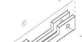


192
PARASOL
CLOSE CONDITION
SEMI OPEN CONDITION OPEN CONDITION


193
fenestration by Alfiya Shaikh
VERTICAL METAL MEMBER
PERFORATED MATEL SHEET 8 MM THICK
TENSON ROD 6MM DIA.
TENSION CABLE 20MM DIA
ROD
194 SPANNING 1 1
4
3
4
5
6
7
DETAIL
DETAIL C
2 3
5 1 MS CLEAT 3MMTHICK 2 BOLT 15MM DIA
TENSION
6 MM DIA. 8 STEEL PLATE 5MM THICK TO ATTACH THE TENTION FORK 9 VERTICAL MEMBER 10 GUSSET 5 MM THICK 11 GLULAM 200MMX100MM 12 BOLT 6MM 13 VERTICAL MEMBER WELDED WITH CLEAT 14 CLEAT3MM THICK 6 DETAIL A DETAIL B 7 8 9 10 2 11 6 3 12 13 14
C DETAIL A DETAIL B
PLAN ELEVATION MODULE DETAIL
Connection of tension cable and module
Connection of tension cable and module with I-beam


Sequence of module in spanning system where angle between module vary because of different end condition.

195 spanning by Jyoti MAli
1 METAL ROD 12MM DIA. 2 GUSET PLATE -1 3 L PLATE 6MM THICK 4 GUSET PLATE -2 5 BOLT 8MM 6 TATA STEEL ADVANCE UK I-BEAM 363MM X 173 MM 7 GUSET PLATE 8MM THICK 8 BOLT 12MM THICK 9 TESION CABLE 12MM DIA
196 SPANNING 2
1 2 3 4 4 3 5
DETAIL
DETAIL C PLAN
DETAIL C
4 6 7 8 9 10 4 5 DETAIL A DETAIL A
B
ELEVATION MODULE DETAIL
DETAIL B
ELEVATION
Connection of tension cable and module with secondary I-beam


Relation of module and tension cable in spanning system
Connection of tension cable and module with I-beam

197 spanning by Afiya shaikh
The objective of the program is to design a school building with focus on expression of high-rise buildings. Initial focus, through the process models was on creating a volume that is light on visual mass. The aim was to reduce the massing as well as breaking the verticality of the structure.


Volumetric Articulation CLIMATE
Daylight and Sunpath Analysis
198 THE LACUNA
1 MAIN ENTRY


2 ELECTRIC SHAFT 1400MMX27OOMM

10 MALE TOILET 11 FEMALE TOILET 12 DRINKING WATER 13 UNIFORM AND BOOK STORE 14 CONFERENCE ROOM 15 ACCOUNT STAFF 16 ACCOUNT OFFICE 17 ASSEMBLY HALL 18 EL.LV


9 0 10 20 50 100


18 19 20 22 21 23 27


19 SUB. T. 20 TRANSFORMER 21 FT 22 DOMASTIC WATER TREATMENT 23 UGT 24 PUMP 25 TREATED WATER 26 CHILLER PLANT 27 SGT 24 25 26 GROUND FLOOR PLAN


199 organization and planning_the lacuna
1 2
3 FIRE SHAFT 1400MMX 1500MM 4 PLUMBING SHAFT 2100MMX1400MM 5 LIFT 6 STOR ROOM 7 ADMIN STAFF ROOM 8 PASSAGE 9 FOYER 13 17

200 8300 3500 6800 3800 6500 7000 6910 4600 4300 4000 1 2 34 5 5 6 7 8 1 1 9 CLASS ROOM PLAN 11 UP UP 8 10 11 12 2 34 5 5 9 10 11 12 INDOOR PLAY AND LOUNGEPLAN 0 5 10 20 50 0 5 10 20 50
CLASSROOM 10000MM X8000MM
ELECTRIC SHAFT 1400MMX27OOMM
FIRE SHAFT 1400MMX 1500MM
PLUMBING SHAFT 2100MMX1400MM
SPILLOVER SPACE 6580MMX8000MM
STAFF ROOM 3500MMX10000MM
LIBRARY PLAN
201 organization and planning_the lacuna 8300
3800 6500 7000 6910 4600 4300 4000 2 34 5 5 9 10 11 12 12 13 13 8
3500 6800
1
2
3
4
5
6
7
8
9
10
11
12
13
14
15
0 5 10 20 50
LIFT
PASSAGE
FOYER
MALE TOILET
FEMALE TOILET
DRINKING WATER
INDOOR PLAY AND LOUNGE
LIBRARY RECEPTION
READING SPACE


202 SECTION


203
SYSTEM
7
3 4 5 6 7 3 4 5 6 1 2
building section and structural system_the lacuna STRUCTURAL
1 CONCRETE SLAB 150MM 2 COMFLOUR 60 TATA STEEL DECKING SHEET 3 GRINDER 100MM x150MM 4 SPANNING SYSTEM 5 TATA ADVANCE UK BEAM 363MMx173MM 6 RCC COLUMN 300MM X600MM
SHEAR WALL
structural system of individual space essential role of spanning system as beam in every floor


206 FENESTRATION DRAWINGS 1 2 3 4 1. Insulated tempered glass 2. Silicone sealant with backer rod Spider fitting and connector 4. Support glass connection 1 2 3 5 1.Transome caps 2. Mullion caps 3. Insulated tempered glass 4. Transomes 5. Mullions 4 DETAIL A DETAIL B


207 fenestration and wall section_the lacuna WALL SECTION 1 SPANNING A 2 150MM SLAB WITH DECKING SHEET - COMFLOR60 3 GLASS RAILING 4 EPF 60 FSS CURTAIN WALL 5 SPANNING B 3 4 5 6 7 5 8 6 TATA STEEL ADVANCE UK I-BEAM 363MM X 173 MM 7 LIBRARY 8 INDOOR PLAY AND LOUNGE 9 DRYWALL 100MM 10ALIMUNIUM FINS 11 CLASSROOM 1 2 9 11 10 DETAIL A DETAIL C DETAIL B DETAIL C DETAIL B DETAIL A LEGEND

208


209 render_the lacuna
Interior render of classroom
Interior render of double hight library
start with abstarct idea of open, close and semi open space
polish that idea while intraducing semi open spaces with glass facade

Final interpretation witth concern of climate and context


column and intermidiate fins follow the same path verticaly where library block aid to cut that verticality. building has plenty of semi open spaces which work as gathering space. building provide a sence of being connected to the ground.

210


211 models_the lacuna


212


213 physical model_the lacuna

The foundation studio for masters in architecture tectonics (MAT) helped in really understating one’s narrative, the right and wrong and delved heavily into details. Each exercises had its purpose and even though it tested our limits, the quality of the product that came from it was very satisfying.
The exercises taught us in different aspects of one’s career. They gave us a deep understanding on machinery, parts, crafting, and team work, from which I understood my strengths and limitations in grounds where I was very unfamiliar with and above all gave good friends and faculties who gave me immense support and inspiration.

Architecture Tectonics had the greatest impact in changing the perception of building, structures and most importantly details. It actually opened the path to make things rather than just design them digitally. The Hands on experience created a huge impact on how much small details matter. It was all a trial and error process which really made one to be cautious about what he is doing. The Spanning’s preliminary exercise part helped to understand how structures work in a system. Every single element of the system has its own purpose and factors. LEARN HIGH is not just about designing a school design and also to make a 1:50 physical model which is actually felt like constructing a actual building which one has to consider the factors like material, labor needed and also a time frame to complete it.

215
PAT22358
Aswin
Sreekumar Suriya Kumar PAT22068

216

217 fenestration by Aswin Sreekumar

218

219 fenestration by Suriya Kumar

220
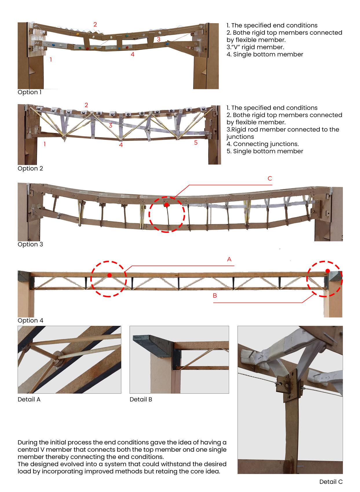
221 spanning by Aswin Sreekumar

222

223 spanning by Suriya Kumar

224

225 organization and planning_learn high

226

227 organization and planning_learn high

228
building section and structural

229
system_learn high

230

231 sectional perspective_learn high

232

233 fenestration and wall section_learn high

234

235 renders_learn high

236

237 physical model_learn high

The foundation studio for the newly introduced Architectural Tectonics was full of explorations throughout the semester. Being a recent graduate, I developed a new perspective to design through this studio at CEPT University.


The studio gave me a close perspective to the importance of design decisions and their correlation with the details. The window exercise helped me to explore different materials as well as components and understand their integrated behaviour. Designing the spanning system gave an insight on how the whole composition of the structural system works and thier effect on forces. The studio concluded with designing a highrise building, which pushed me to cross my limits in terms of the production process as well as looking into minute details that are essential.
The architectural tectonics foundation studio at CEPT University has been a challenging yet rewarding roller-coaster trip for me. This studio not only revitalized my body and mind towards the fundamental design approach and process, but it also enhanced the depth of it.
Each exercise was unambiguous in terms of its objectives and learning outcomes, and it dispelled the myth that these outcomes may only be felt at the conclusion of the exercise. I now place the same value on completion as I do on the process. The workshop, which is an important component of the studio, increased confidence and provided insightful information on the harmony and tolerance between material-machinery-body.
239
Hetansh Patel
Prateek Bansal
PAT22134 PAT22255
The designed masterpiece is a vertical sliding folding window, made up of timber and acrylic. The dimensions of the window are 460mm x 460mm. The mechanism of the window is different from the typical design mechanism available in the market. The unique mechanism of this window is one of the features which stands out more than the others.
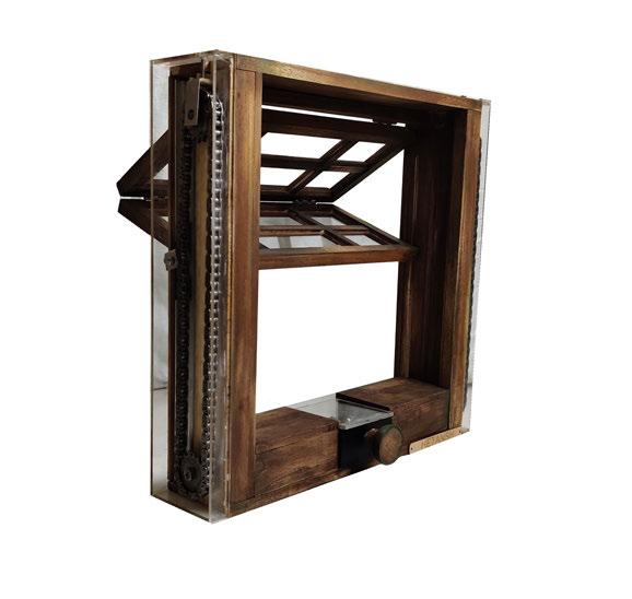


Mechanism and Material Template:
Mechanism and Material Template:
Length
8/13 Gear Chain 8/13 Sprocket (SDF60)Aluminum Channel Roller Size: 100 Size: CustomSize: 60(1) Chain Connector Size: Custom SS L-Clamp Size: 25
SS L-Clamp Size: 25 Chain Connector Size: Custom
8/13 Sprocket Size: Custom
(SDF60)Aluminum Channel Roller Size: 60(1) (SG120)Aluminium Channel Size: 460
SS U-Angle Size: 20x20x40
Ballbearing 5mm Bolt Nut
Components of window Open Condition Front elevation of window
Bevel Gear Size: 25 Nail Screw Flat Bottom Screw Size: 25 Size: 25 Size: 35
SS U-Angle Size: 20x20x40 Size: Custom 5mm Bolt Size: 80x5 Size: Custom Screw Size: 25
Size: 600X8 STUDIO
Threaded Rod Size: 600X8 Size: Custom Nut Size: 8 OD Flat Bottom Screw Size: 35
Width FOUNDATION
240
Used: ~ Measuring Tape or Ruler ~ Right Angle ~ Hammer ~ Small Hacksaw ~ Screwdriver ~ Marking Gauge ~ Pliers ~ 1”,1/2” Chisel ~
~
vertical
Tools
Bandsaw Machine
Mighter saw CHAIN REACTOR
sliding folding window
~Bandsaw Machine
~Mighter saw ~Router ~Drill Machine ~Planer Machine ~150, 220 Sandpaper ~4mm Threading Tool
Threaded Rod Size: 10|22Size: 80x5Size: 8 OD
(SG120)Aluminium Channel Size: 460 *All units are in millimeters
8/13 Gear Chain Size: 100 Bevel Gear Size: 25 Ballbearing Size: 10|22 Nail Size: 25
Step 1
Assemble the vertical members for the frame.
Step 2
Screw the aluminum channel in the slot of vertical member.
Step 3 Step 4
Fix the mechanism onto the frame and add the outer box to hang it from top.
Assemble the handle mechanism in the box and fix it to the frame.
Step 5 Step 6
Assemble the window panel.
Attach the panel to the main frame with screws from the top & connect it with the chain.
241
fenestration by Hetansh Patel
HETANSH
|
1.1 HETANSH
|
EXERCISE
PATEL
PAT22134
PATEL
PAT22134
horizontal hinged window
The founding principle of tectonics foundation studio is “MAKING FIRST.” This activity was designed to help students get practical knowledge of the materials and their limitations when used alone or in combination with other materials. A mechanically driven horizontally operated system measuring 460mm by 460mm is the subject of the project. A prototype is experimented in with a material pair of metal and bamboo.
CONCEPTUALIZATION
The design is motivated by the proportion of metal to be employed with bamboo as the frame, in order to limit the device’s overall weight. The mechanized slit-like opening in the window frame opens and closes utilising a simple handle lever system which is furtherlinked to tension cables.
Vision of device as a slit in frame

KIT OF PARTS USED

The procedure started with choosing a proper bamboo for the frame and learning how it was processed. Next, slits and a handle were sliced out of 2mm thick MS sheet. From other stores, smaller mechanical components were acquired.
The constraints I had to respond to were the tools and equipments I had access to, as well as the tolerance of the material with regard to its size.
Ball bearing 19:OD | 6:ID
M-hook Nut-bolt 3”-long

Metal wire, 1.5mm dia

Roller tyre, 16mm dia.
SS washer, 16mm dia
Cable sleeve Screws 2”-long
242
PEEK-A-BOO
tools used for bamboo cutting


243
bamboo (~50mm dia) Solid bamboo (~32mm dia) SS and aluminium sections Chopped bamboo slats | Grinding finish Solid bamboo corner joinery Hinged MS fin, Handle and other parts
fenestration by Prateek Bansal THE MAKING From market to workshop Hollow
1. Assemble the ball bearings in vertical bamboo member + Metal fin + Bamboo frame.
2. Insert all the hooks in place + fix handle in the slot with nut-bolt + fixspring in place with handle.

3. Stick all the bamboo slats.
4. Pass the tension wire from handle-through hooks and metal fin.


244 ASSEMBLY DRAWINGS
Peek-a-boo, a horizontal hinged device, made in bamboo and metal

245 fenestration by Prateek Bansal PROTOTYPE OUTCOME
The purpose of this exercise was to create a span system and stabilise an OHP sheet with evenly distributed force over it using the provided materials, which are scaled-down copies of the actual rigid-flexible and thread materials. The exercise began with exploring the forces acting in a spanning system corresponsing to the modules decided. The material used in model were jute board (rigid material), thread (flexible material), and paper (flexible material). The compinents were joined using pin or rigid joint.


The overall motive of this exercise was to understand the behaviour of different spanning system. Different materials and their properties were explored which brought out an interesting outcome.
End Conditions of the spanning system Points junction end condition forming a ‘Y’ shape.

246
models Quick explorations done to get an understanding of the system Process model - 1:10 First exploration of the whole spanning system in place SPANNING 1
Conceptual
Process model - 1:10
Alternative showing the effort to lighten the spanning system by reducing the members
Detail Module - 1:10
Models showing the details and the various joinery applied
Part model - 1:5


Models showing the details and the various joinery applied
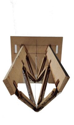


247 spanning by Hetansh Patel
50mm dia ms loop to 30mm dia pipe
30mm dia metal cord

12mm thk ms clamps


glulam wood beam 200x300mm

248 (M22)AT 4000 FOUNDATION STUDIO Specification Legend 1.
2.
3.
4.
5.
6.
7.
8.
9.
10.
11.
12.
13.
1 3 2 13 D1 D2 D1 D2 D3 D3 4 5 6 7 910 11 12 8 View along with the material and the various components Isometric View
ISMB 600 Primary Beam
25mm base plate (For timber beams)
10mm shield wall anchor fastener
15mm thk timber planks
12mm thk ms struts
10mm dia aluminum rivets
25mm clevis pin
140mm dia-80mm high ms cylinder for clevis and yoke joinery
6mm thk ms plate Gusset Plate with hook for cord connection
End Condition of the spanning system
Final Model - 1:10 Detail 1 Detail 2 Detail 3
Top view of the spanning system

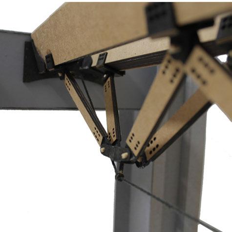


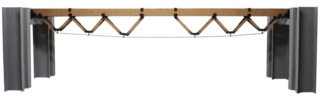
249
Single module of the system Detail 4 Connection of modules
spanning by Hetansh Patel
Through a series of modelling experiments, the goal was to discover and comprehend force behaviour on the spanning system. Given the provided materials, which were scaled-down versions of the genuine rigid, flexible and thread-like materials, the aim for this exercise was to develop a span system and stabilise an OHP sheet with uniformly distributed force over it. After the stability was established in a diagram, real materials in distinct sizes came into play and joineries at each point were detailed out.


Understanding forces


250
Arriving at a stable force digram 1:10 sacle model for 10m span Tension in upward direction Revrse arched Compression in downward direction
end conditions Iteration 01 Iteration 02 Iteration 03 SPANNING 2
Opted


251 spanning
Specification legend 1. ISMB 600 beam 2. 25mm thk MS gusset plate base 3. 25mm plate with hooks Deatil - D1 Deatil - D2 Deatil - D3 4. Turnbuckel hook 5. 12mm thk MS top cap 6. 12mm dia rod welded on clamps 7. 12mm dia fixing bolts 8. 12mm dia fixing bolts Timber lapped sandwiching an MS plate in between Long span beams isometric view Fixed on a primary beam Final model images 1:10 scale model expressive details expressive details 9. 12mm thk MS bottom cap 10. 1200mm long glulam wood beams (75x150mm) 11. Timber member 75x100 mm cross-section 12. 18mm dia hexa-bolt 2 3 4 1 5 6 1200mm long glulam wood beams (75x150mm) Galvanized structural steel tension cable (12mm dia) Timber sections joined as per detial 7 8 9 9
by Prateek Bansal
Sports Centres are places that bring thousands of people together and create a sensational architectural atmosphere. They are highly emotional places of identification and devotion. At the same time, they are modern locations which have to function extremely precisely and efficiently. They often have their monumental presence in big cities. They also create the identity of the city and place due to high digital consumption of sports.


252 TRIPLE-RIPPLE
Program outline: Indoor sports and Institute 60% Fitness 20% Cultural spaces 10% Auxiliary spaces and services 10% Design Objectives: 1. Inspiring and Integrating 2. Adaptability 3. Efficient 4. Educate 5. Inclusive High rise development model scale 1:250 High rise development model scale 1:250 Final massing model scale 1:500 Conceptual expression model scale 1:500 Conceptual expression model scale 1:500 Expression model responce to site scale 1:500 Massing expression development
A.
B.
Structure grid evolution from program for the given site.
A. Compromise on auxiliary spaces.
B. Relativly more auxiliary floor space.
Allowed footprint and mass on site Setting out core at edge away from stadium face
Fire staircase open form all three sides
Program stacking arrangement (from bottom to top):
•Open to public podium
•Sports training
•Fitness - Gym + Medical and dining block
•Administration block
Climate responce
Defining floor plates and podium Combining and exaggerating volumes, Modular formation. 3 Levels = 1 Module


Ground volume with singular roof, responce developed to ground.

Skin development with module, to respond climate and program behind.

253 organization and planning_triple-ripple
Climate orientation
South sun effect on flat facade
South sun effect on undulated facade
Building development and organization diagram
BUILDING PLANS
Typical floor plan layouts


Typical double height lower level layout
court
Typical double height upper level layout Badminton court
Layout legend


1 Floor lounge (double height) 2 Lift lobby 3 Toilet female 4 Toilet men 5 Electrical room
room
Badminton court (6.1m x 13.2m)
walkways
room
free break-out zone
11 Office plaza
cultural plaza
roof terrace
dinnig terrace
254
Badminton
N 1.0 M 0.0 M 10.0 M 5.0 M N 1.0 M 0.0 M 10.0 M 5.0 M 6 AHU
7
8 Peripheral
9 Players
10 Noise
12 Open
+
13 Open
2 3 3 6 6 7 8 8 8 8 9 9 10 6 6 4 4 5 5 5 5 1
Typical office floor layout


Office plaza
Open terrace level layout


Private terrace

255
N 1.0 M 0.0 M 10.0 M 5.0 M N 1.0 M 0.0 M 10.0 M 5.0 M 2
organization and planning_triple-ripple
3 3 6 6 12 13 11 6 6 4 4 5 5 5 5 1
Steel channel sections (200mm x 150mm)

Steel box section frame for skin (200mm x 200mm box)
Skin infills (Glass, perforation and louvers)
Exploded structure diagram for single storey module Building exterior render


storey of a
Rcc slab fill
Slab reinforcement
Steel deck slab (Colflor-80)
Steel seck slab (80mm cover : 12mm dia reinforcement bar)
Edge trim fixed to beam for fixing deck slab
Secondary span beams
Cantilever beams


Secondary beams (Steel ismb 300)

Primary beams Twin steel cahnnel section column
Composite span beam
Steel i-section tapered beam (600mm : 300mm deep x 300 mm wide)
Steel i-section beam (600mm : 300mm deep x 300 mm wide)

Twin steel cahnnel section column (600mm x 700mm)
building section and structural system_triple-ripple

257
Full height section


Blown up section of one Blown up section of one module

258
SECTION
SECTION
WALL
Fenestration drawings
FENESTRATION- DETAILS

Detail- D4
100 X100mm Aluminum box section for DGU glazing
12mm thk MS casted angular end clamp

150mm MS channel section fixed to cantilever beam
Hand rail bolted at the slab edge
Detail-D3


Detail-D2
Detail-D1
50 X 75mm MS box section
600mm wide MS louver clamp to hold wooden plank 300mm MS angle section
200 X 200mm MS box section
65mm thk. MS grated flooring 12mm thk MS casted center clamp
150mm MS channel section
25mm thk Flooring
150mm thk Steel deck slab (colflor-80)


150mm Edge trim and MS angle for caping
6mm thk gusset plate bolted at extension
Cantilever beam


MS bracket under beam junction
fenestration and wall section_triple-ripple


259
one
drawings
module


260 SECTIONAL PERSPECTIVE
ht. Lift lobby
lobby
level
Double
Lift
Concourse
Upper lounge A Typical sectional view of a module. A module = 3 floors Badminton court
Mezzanine level Seating zone Break-out zone Badminton court


261 sectional perspective_triple-ripple
PHYSICAL MODEL MAKING
Scale 1:50
Office and terrace responce to sky
Full height building model made in MDF and Plywood Scale 1:50


262
Fire staircase popping out between shear walls
Building interior space in daylight. Double ht. badminton court. Scale 1:50


263 physical model_triple-ripple
The buffer space between skins Harmonial scaled composition

This studio gave me a new perspective on the detailing process and the language of expression of a design. As I continue to develop my understanding of details, I started to see different levels of complexity that an architectural work can embody. Design opening introduced us to mechanisms and different machines in the workshop. Second exercise introduced us to the nature of forces on spanning structures and the way of its articulation. Different types of materials were explored in the spanning system. And the third exercise was designing high-rise that deals with all the acquired skills. We had to consider spanning, fenestration details, columns beam requirements, building expression, material use, sustainability and space organization. Whole process made me understand what to consider and how to make it all work together. I learned the process of making along with design in this studio.
The foundation studio led by Prof Sankalpa and Neel broadened my horizon, when it comes to understanding the relationship between Designing and Detailing. Focused on the process of Making - from understanding, designing and developing the mechanism of a window to designing and detailing the form, structural and non-structural elements of a Highrise, it inculcated a very hands-on approach to the process. The studio also helped me deepen my understanding and further develop my skills to be able to understand, analyze and detail out systems at different scales. I would like to thank Prof Sankalpa, Neel and Teaching Associates - Hemanshu and Divya for this amazing experience!


265
PAT22402 PAT22228
Vrushali Mali Nishiki Varma

Parallel Motion Window - Vrushali
PARALLEL EDGES
fenestration by Vrushali Mali
SYNTHESIS HORIZONTAL BLINDS
Synthesis is a combination of two processes in the horizontal blinds, one being opening and closing of the Louvers (individually) and the second being the up and down motion of the Louvers (Together). The original mechanism of the horizontal blinds involved strings, pulleys and gears. The idea behind the designed mechanism was to remove one component i.e. to not use gears but to work the entire system only with the help of strings and pulleys. With that in mind I wanted the system to have a components on the sides where it could be guided by a more structured set of components formulating the mechanism, which is ultimately working on strings and pulleys. So, the mechanism has been developed with the idea of mechanical pin joints inspired by the scissor mechanism, but modifying it to make a different and integrated system connecting both the operations.
The materials used in the assembly are Timber (to prove a sturdy frame), MDF and Acrylic (for the Mechanism), joined by nuts and bolts of different sizes, along with Stainless steel Pulleys (Bobbins) and a thin but strong String.
The key highlights of this mechanism is the design of the mechanism components with it self adjusting properties as it is set in motion. This mechanism since it is my take on the mechanism of horizontal blinds, it can be used on the inner side of windows which are fairly lower in height.

BASE FRAME ASSEMBLY
-Attach 2 pieces of Mechanism Part C as spacers to the channels with Feviquick or EvoBond -Insert 6 pulleys in each channel -Align Assembly A between the 2 pulley sets in the channel assembly -Join Assembly Assembly B on both sides with the holes aligned with the pulleys (as shown in drawing) with Nut and Bolt Set A
DETAIL A
Open Close Mechanism for Louvers Assembly A Attach 1 piece of Mechanism Part B to Mechanism Part A with Feviquick 25
JOIN THE FRAME PART A, B, C AND E WITH SCREW TYPE A AND L-ANGLE CLEATS AS SHOWN IN THE DRAWING ABOVE
MECHANISM SUPPORT, UPPER PULLEY MECHANISM AND LOCK ASSEMBLY
Upper Pulley Mechanism Assembly B (Left Side of the Frame)
Assemble, with the Mechanism Rod B passing through the Centre, in the following order:
Pulley Stopper - PulleyPulley Stopper - Leave 5MM gap - Pulley Stopper - Pulley - Pulley Stopper
Attach 2 pieces of Mechanism Part C with Feviquick Join this assembly to Frame Part B with Nut and Bolt Set C
Upper Pulley Mechanism Assembly A (Right side of the Frame)
Assemble, with the Mechanism Rod B passing through the Centre, in the following order:
Pulley Stopper - Pulley - Pulley Stopper
-Attach the 2 pieces of Mechanism Support Part B aligned with the edges of the timber frame and the MDF Back Frame
-Attach the 2 pieces of Mechanism Support Part A aligned with the edges of the timber frame
-Attach the Pulley Support Part A to all 4 Mechanism Parts while aligning the holes in the centre
-Attach the Channel base, Upper Pulley Mechanism and the Locking Mechanism as shown in the Drawing
-But keep the Knob Unattached
Insert Channels with the Mechanisms into the Channel Support and Hammer it (gently) from the top to set it inside the support firmly
- Join the Louver connectors Close Mechanism on and Bolt Set C - Attach the Louver Panels the Mechanism Part Close Mechanism Assembly while aligning the centres
268
Frame Part A, B and Material: Timber Board Dimension: 460X90X12 Quantity: 3 Assembly Mechanism Rod A Material: Stainless Steel Rod Dimension: 4 dia X 150 Quantity: 2 Mechanism Material: Steel Dimension: 100 Quantity: 460 90 Category A: Category B:
DETAIL
MECHANISM
A
and C Board 460X90X12
Frame Part D Material: MDF Dimension: 460X100X5 Quantity: 1
Mechanism Rod B
Frame Part E Material: MDF Dimension: 460X460X8 Quantity:
Frame Part F Material: MDF Dimension: 460X4600X5 Quantity: 1
Mechanism Support A Material: MDF Dimension: 100X40X5 Quantity: 2
Pulley Support Part A Material: MDF Dimension: 15 diaX5 Quantity: 8
Pulley Stopper Material: Rubber Dimension: 15 dia X5 Quantity: 12
Mechanism Support B Material: MDF Dimension: 50X50X5 Quantity: 2
Mechanism Pulley Part B Material: Timber Dimension: 20X20X11 Quantity: 2
Mechanism Support C and D Material: MDF Dimension: 47X67X5 Quantity: 2
Category E: Lock Mechanism
Mechanism Pulley Part A Material: Timber Dimension: 45X45X5 Quantity: 4
Thread Material: Thin Nylon Dimension: 1 Dia X 3000 Quantity: 1
ASSEMBLY PART A
Channel Material: MDF Dimension: 440X21X5 Quantity: 4
Louver connector Material: MDF Dimension: 280X15X5 Quantity: 4
Louver Panel Material: MDF Dimension: 280X100X2 Quantity: 4
DETAIL B
Mechanism Part A Material: Acrylic Dimension: 60X15X5 Quantity: 28
Up Down Mechanism for Louvers Assembly B
Join Mechanism Part B, Part A and Part C (in this order) with Nut and Bolt Set C
Mechanism Part B Material: Acrylic Dimension: 45X15X5 Quantity: 28
Mechanism Part C Material: Acrylic Dimension: 30X15X5 Quantity: 22
MECHANISM ASSEMBLY PART B
Lock Part C Material: MDF Dimension: 40X80X8 Quantity: 4
Lock Spacer A Material: Timber Dimension: 75X10X5 Quantity: 2
Lock Spacer B Material: Timber Dimension: 40X10X5 Quantity: 2
Lock Part D Material: MDF Dimension: 35X8X8 Quantity: 2
DETAIL C
connectors to the Open both sides with Nut Panels on both sides on C set of the Open Assembly with Feviquick, centres of both the parts
Align and Join the 2nd hole of the Mechanism Part C on both sides with Nut and Bolt Set A (as shown in the drawing)
DETAIL C
Open Close Mechanism Pulley Assembly
Cut the Pieces to sizes given in the catalogue in Timber and drill holes in the Mechanism Pulley Part A with a 5mm drill bit
Lock Part B Material: MDF Dimension: 35dia X5 Quantity: 2
Attaching Thread for Up Down Mechanism
Attach the 2 Mechanism Pulley Part A on both Sides of Mechanism Pulley Part B with Fevicol SH Add the Pulley in the Assembly with Nut and Bolt Set B Make 2 sets of this assemby for both sides
Tie the Thread to the Last Piece of the Channel Mechanisms on both sides, run them through the Upper pulley mechanism sets and tie it to the Lock Mechanism pulley (as shown in the Drawing above)
Attaching Thread for Open Close Mechanism
Tie the thread to the Louver Panels on both sides, Pass them through the Open Close Pulley Mechanism Assembly and tie it to the Lock Mechanism pulley (as shown in the Drawing above)
269 fenestration by Nishiki Varma
Assembly Part Catalogue
Material: Stainless Steel Rod Dimension: 4 dia X 100 Quantity: 2
- angle Cleat
Stainless Steel Dimension: 20 outer Dia 5 inner Dia 20 Length Quantity: 31
and Bolt Set A
Nut and Bolt Set B
Nut and Bolt Set C +
4
Screw B Material: Stainless
Screw A Material: Stainless Steel Dimension: 3 Dia X 12
Support Material: MDF
460 100 440 430 34 8 340 15 8 280 120 40 40 40 60 15 15 45 30 15 8 8 8 8 8 42.5 15 42.5 17.5 15 17.5 12..5 15 15 17.5 47 67 37 17 460 460 460 460 15
Part A Material: Plastic 3D
Knob
A: Frame B:
Category D: Hardware
L
Material: Mild Steel Dimension: 55X55X15 Quantity: 4 Lock Spring Material: Mild Steel Dimension: 5 dia X40 Quantity: 2 Pulley Material:
Nut
Material: Stainless Steel Dimension: 4 Dia X 60 Quantity: 22
Material: Stainless Steel Dimension: 5 Dia X 40 Quantity: 2
Washer Material: Stainless Steel Dimension:
Dia X 20 Quantity: 20
Steel Dimension: 3 Dia X 25 Quantity: 8
Quantity: 34 Channel
Dimension: 47X67X5 Quantity: 6
Lock
Printed Dimension: 30 diaX64 Quantity: 2
Material: Plastic (3D Printed) Dimension: 65X65X24 Quantity: 2
Mechanism Category C: Mechanism Support
DETAIL B
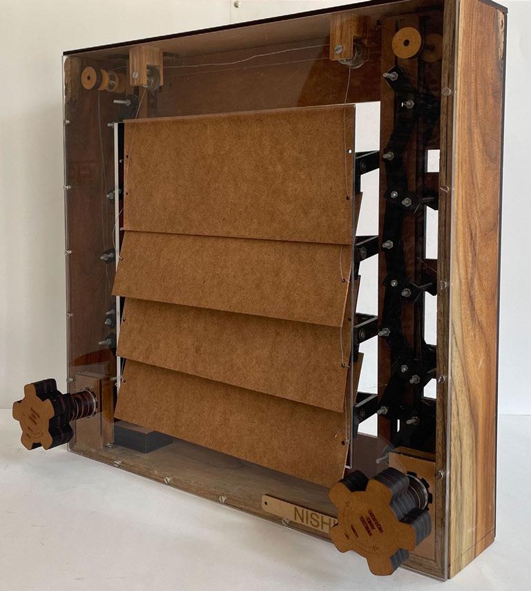
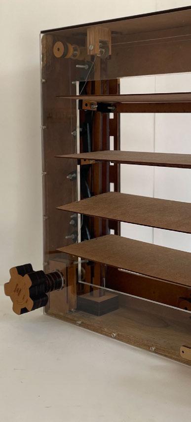
270 SYNTHESIS FINAL OPERATION | STAGE 01 CLOSED OPERATION PARTIALLY OPEN - OPEN-CLOSE


271 fenestration by Nishiki Varma | STAGE 02 OPEN-CLOSE MOTION OPERATION | STAGE 03 COMPLETELY OPEN - UP-DOWN MOTION
SPANNING DESIGN 01 - Vrushali

End Condition 01: 6 Points
End Condition 02: V (Profile)
Material:
- Engineered Bamboo (Vertical Members)


- 50mm thk MS Box Section (Top cord)
- 15mm thk SS pipes
SPANNING DESIGN 02 - Nishiki

End Condition 01: 3 points
End Condition 02: 1 Line
Material:
- 60mm thk Timber [Triangle Members]


- 10mm thk MS Plate with profile cutting (assembled as a box section) [Top Cord]
- 15mm thk steel rope cable [Bottom Cord]

272
10mm thk MS angle Cleat (60 degree) welded to internal plate
10mm thk MS plate welded to internal plate (for attaching Top Cord)
10mm thk MS plate welded to internal plate (for attaching Top Cord)
5mm thk groove inside timber piece for MS plate
25mm thk MS Plate Laser cut according to Design 250mm wide and 60mm thk Timber cut according to design
36mm dia, 180mm long nuts and bolts to join the module assembly
Module Assembly (Straight Triangle)
10mm thk MS angle Cleat (60 degree) welded to internal plate
25mm thk MS Plate Laser cut according to Design
5mm thk groove inside timber piece for MS plate
250mm wide and 60mm thk Timber cut according to design
36mm dia, 180mm long nuts and bolts to join the module assembly
Profile cutting of top cord (with arch for better performance in compression and to also reduce the material). Laser cut MS sheet according to file shown (assembles as a MS Box Section)
Module Assembly (Inverted triangle)


36mm dia, 180mm long nuts and bolts to join the module assembly
Top Cord Fabrication
5mm
Bend the Sheet along the Red (etched) lines, welded and secure them with nuts and bolts along the holes
150mm dia, 350mm long MS Cylinder (Sand casted according to design) to weld the Top Cords and Triangle modules (at different angles) together

Top Cord Assembly
Triangle
Bottom Wire Assembly (run through wire holes in triangle modules, held in place with stoppers after posttensioning)
273
Assembled Module
Assembly (Top Cord + Triangle Modules + Bottom Wire) End Condition assembly 1 (3 Points) 3D Axonometric View of Entire Spanning Assembly Attached to Column-Beam System End Condition assembly 2 (Line)
Assembled Module
Top Cord Assembly Spanning
plates
Thk Top Cord Joinery MS
Laser Cut according to design (Attached by welding)
Top Cord (Compression) Bottom Wire (Tension) 5mm Thk Top Cord JoineryMS plates Laser Cut according to design 800x800 IS I-section Structural Steel Beam 800x800 IS Cruciform-section Structural Steel Column 60mm Outer Dia x 100mm long Rope Wire stoppers (to hold the post tensioned wire in place) 15mm Dia Metal Rope wire (post-tensioned for bottom cord)
Bottom Wire Assembly
Modules Welded to Top Cord Assembly
900x500x25mm MS end plate Laser cut according to design (placement of holes) 400x550x25mm MS end plate Laser cut according to design (placement of holes) Line End Condition Inverted Triangle Assembly Straight Triangle Module Compression Bottom Wire (Tension) 225x150x30mm MS Box Section for End condition joinery
Thk Top Cord Joinery MS plates Laser Cut according to design
5mm
Frag-Play is an indoor sports raining environment. To break the rigidity and monotony of the defined sports areas and their requirements - Fragmentation of spaces and volumes are done from Macro to Micro scale. The fragmentation design with respect to 3D grids (6x6x4.5m for macro and 200x200mm for micro) which are derived according to the standard requirements of the different types of sports’ courts. With the service cores on the east and est side of the building, the programmes are oriented in the North-South direction for maximum variation of natural light. Supporting and complimenting the open plan aspect of the design the structural system is derived to incorporate larger spans of column-free spaces, while enhancing the framentation concept through its design (Cruciform Columns appear to be fragmented due to their profiling and form).
Moving to Micro Scale - the Facade of the strucutre is also derived from the grid and designed according to the functional requirements to provide a combination of direct and diffused light, thus further enhancing the experience of the users. A combination of different types of facades is in- corporated [vertical louvers, grid design, horizontal louvers and FRP panelled walls (with a variety of opaque, transparent and translucent panels designed according to the functional arrangement)]
Building Organization Diagram
Marking Layers of Programe Catergories according to Public, Semi-Public and Private
Fragmentation of Layers (with respect to 4.5M Vertical Grid) according to Function Height requirements (Indoor Sports areas requiring larger clear heights9-12M)
Fragmentation and Sub-Division of the Layers according to the Size requirements of the Specific Functions

Removing Fragmented volumes between different functions to create Voids, Green Spaces and allow for wind flow through the structure
Public and Cultural Spaces
Semi- Public Spaces - Indoor Sports Private SpacesSports Institute Service and Circulation Cores Green Terraces
Moving Volumes in North and South direction (according to functional requirements and design) to further enhance the Fragmented form of the Design
Adding Horizontal and Verical Circulation along with Service cores on the East and West Facade to:
- Create access on both sides of the structure
- For Structural Support on East and West side of the Building
Developed Form of the Design through Different layers of Fragmentation according to Functional requirements, responding to the site and context
274 FRAG-PLAY
MAT PLAY
CROSS ROAD B’
Voids according to Southwest windflow EXTERIOR VIEW NORTH FACADE EXTERIOR VIEW SOUTH FACADE
DHARNIDHAR A’ A
N
Overall Context Plan N


Building orientaion to vantage points of surrounding context from all heights Orientation according to sunpath of Ahmedabad Constructed Road Stadium Vegetation B
N
Existing road Sports Center Site Plan
Climate Diagram SCALE - 1:200
organization and planning_frag-play
SARDAR PATEL STADIUM ROAD


Typical Floor Plans
typical floor plans_frag-play SCALE - 1:200 N
Terrace 131.0M
Canteen 126.5M
Library, Research + AV Room 122.0M
Library + Research 117.5M
Multipurpose Room, Coaching Room 113.5M
Medical + Physiotherapy Floor 108.5M
Team Room + Sports Head 104.0M
Basketball 95.0M
Gymnastics + Martial Arts 81.5M
Wrestling + Boxing 72.5M
Chess, Table Tennis + Squash 63.5M
Acrobatics, Rock Climbing + Skating 50.0M
Badminton + Turf Cricket 36.5M
Auditorium +Theatre 27.5M
Gym + Meditation 23.0M
Gym + Yoga 18.5M
Gallery + Admin 14.0M
Restaurant 9.5M
Podium 5.0M
Ground Floor 0.0M
278 SECTION AA’
Depicting Internal Fragmentation inside the building design
I-section and Double I-section Beam Grid and Cruciform Section Column - for smaller spaces of the Sports Institutea


I-section and Double I-section Beams with Spanning systems and Cruciform Section Column - For larger spans of the sports areas
I-section and Double I-section Beam Grid and Cruciform Section Column - for the combination of different sizes of the Public and Cultural Spaces
I-section Beam Grid and Cruciform Section Column - Offset 6M for Podium (Public spaces, Services and Parking areas)
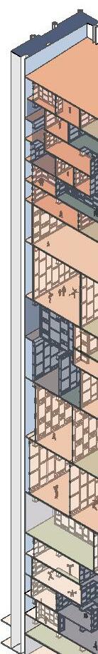


Public and Cultural Spaces
Semi- Public SpacesIndoor Sports Private SpacesSports Institute Service and Circulation Cores Green Terraces
279
building section and structural system_frag-play STRUCTURAL SYSTEM
Depicting Internal Fragmentation inside the building design cut axonometric Section bb’ with both spanning
structural details STRUCTURAL BAY MODEL
Structural Diagram
designs,
Depicting details of the North and South Facade (Both Static and Dynamic)


- Detailing the Section of the 1.8m wide walkway on south facade (curtain wall)


- Slab types and details (Decking slab and different types of layered slab for green buffer spaces)


- Structural Details and arrangement along with spanning arrangement varying through the building as per the requirements aof the functions


280
Perspective
through 3
south facade detail
Sectional
-
floors along with north and


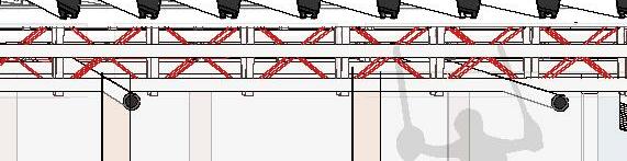


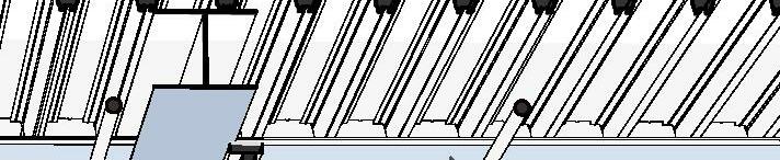


281 sectional perspective_frag-play
WALL
BRICK
500
SMALL
AIR
FIRE-FIGHTING
1.8M WIDE
800X800MM MS
450MM DEEP
ROOT
MS TOP CORD 15MM THK METAL ROPE WIRE
POLYURETHANE FLOORING INCLINED PLANE DETAIL
AT EVERY 4.5M FOR COLUMNN STABILITY 150X150X10MM MS EQUAL LEG ANGLE CLEAT 800X800X20MM I-SECTION MS GIRDER SLIDING
100MM
ComFlor 225 METAL DECKING DETAIL FLOORING (METAL DECKING) FOR SERVICES PIPES GRID DESIGN (FACADE)
DESIGNS (MS FRAME WITH FIBRE REINFORCED PANELS)
PARAPET WALL TERRACE GARDEN PLANTATION HORIZONTAL DUCSTS FOR SERIVICES
MM DIA PIPE FOR SERVICES AND WIRING OF DYNAMIC FACADE SPANNING DESIGN 01
TREES AND BUSHES PLANTATION (500MM THK)
DRAIN
PIPES
WALKWAY ON SOUTH FACADE
CRUCIFORM COLUMN
SOIL LAYER
BARRIER
TENSIONED BOTTOM CORD
(STIFFNERS)
WINDOW WITH LOW-E GLAZING SPANNING DESIGN 02 CORRUGATED DRAINAGE
THK PCC IN SLOPE (1:76) TOWARDS DRAINAGE PIPE WATERPROOFING WITH 3MM PLASTOMERIC BITUMEN COMPOUND - TEXSA MAKE OR EQUIVALENT SLURRY MIX OVER SLAB
STRUCTURAL DETAILS
Material: Structural Steel coated with Intumescent Coating for fire safety Cruciform Column Joinery: I-section and T-section - joined together with welding and 150x150x10mm MS Equal Leg Angle Cleat
FENESTRATION DETAILS

Material:
External Frame - 100x100mm Thk MS box section (Welded)
Internal Frame - 50x100mm Thk MS box section (Welded)
Glazing - 10mm thk Low-emissivity double glazing for better performance
A combination of Transparent glass (for lower sliding window) and Translucent/Frosted glass [depending on the function (for the upper fixed windows)]
FACADE DETAILS
GRID FACADE ASSEMBLY:

Material: Frame - 100mm Thk MS box sections (Welded)

Internal Grid Detail Elements - 60mm Thk Timber (Assembled with Tenon and Mortise Joints)

VERTICAL LOUVERS ASSEMBLY:
Material: Frame - 100mm Thk MS box section (Welded)
Internal vertical/horizontal louvers - 60mm Thk Timber (Assembled with Tenon and Mortise Joints).

283
detail_frag-play
fenestration and facade
Timber Module Assembly
Grid Facade Design Layers
Vertical Louvers Design Layers


284
Showing Fragmentation of Form Exterior view - north facade
Exterior view - South facade
Design of the South Facade according to the functions
Interior view - boxing and wrestling

Visually interconnected and overlooking spaces derived from the fragmented design for a more connected and involved experience for the users


285
renders_Frag-Play


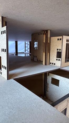


286 PROCESS MODELS 1:50 MODEL INTERIOR VIEWS


287
model_Frag-Play 1:50 MODEL EXTERIOR VIEW
process models and physical


Trusting the process


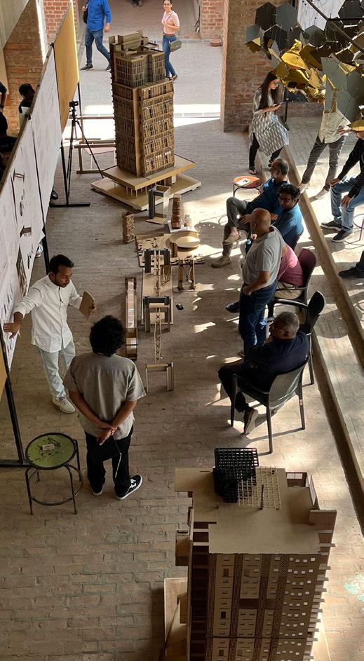
Editorial Team
Compilation : Amrita Das, Selvin Varghese, Saurabh Narsikar Graphics : Diksha Garg, Miloni Patel Proof Reading : Devashree Chaudhari, Manasvi Patil
290
The architect’s general task is to provide a warm and liveable space. Carpets are warm and liveable. He decides for this reason to spread one carpet on the floor and to hang up four to form the four walls. But you cannot build a house out of carpets. Both the carpet on the floor and the tapestry on the wall require structural frame to hold them in the correct place. To invent this frame is the architect’s second task.
 - Adolf Loos, ‘The Principle of Cladding, 1898


