25-0602
Let’s build the
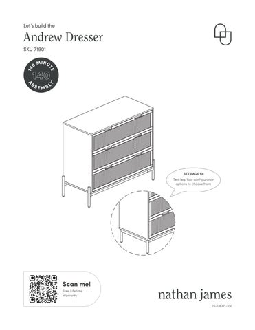
Andrew Dresser SKU 71901 0
MINU
L
Y
14
A
SS
TE
140 EMB
SEE PAGE 13: Two leg/foot configuration options to choose from
Scan me! Free Lifetime Warranty 25-0627 -VN
25-0602
Let’s build the
Andrew Dresser SKU 71901 0
MINU
L
Y
14
A
SS
TE
140 EMB
SEE PAGE 13: Two leg/foot configuration options to choose from
Scan me! Free Lifetime Warranty 25-0627 -VN