What’s included - Part two
Begin by attaching the handles. Take the two handles (J) and position them inside the drawers, aligning the holes. Use the M3x12mm Screws (K) and a screwdriver to securely attach the handles to Top Sub-assembly (1).
Step 2
Flip the Top Sub-assembly (1) onto its back, ensuring it is upside down. Attach the Anti-tip Bracket (Q) using the M4x14mm Screw (S) and your screwdriver. After completing this step, take the Door Catcher (N) and secure it in place with the M3x15mm Screws (O) and your screwdriver. Next, referring to the provided image as a guide, insert the Ø6x34mm Cam Bolt (B) and Ø6x30mm Wooden Dowel (C) into their designated holes.
Grab components 2, 3, and 5. Insert the Cam Bolts (B) and Wooden Dowels (C) as shown in the accompanying imagery. Place the Cam Bolts (B) into the top holes and insert the Wooden Dowels (C) on the sides. Step 3
C X6 X10
Once Step 3 is complete, attach the Right Side Panel (3) to Back Panel (5) by aligning the two Cam Bolts (B) with the corresponding holes on Back Panel (5). Use the Cam Locks (A) to fasten the pieces securely in place. Step 4 A
5 3 A A
How to use cam locks
Did you know?
Cam locks are used to join t wo panels together, usually the edge of one to the flat side of another.
First, your cam bolt (or cam pin) will need to be properly inser ted into the flat side of the board.
Import ant Note: Only tighten the cam bolt until it is secure. Do not over-tighten.
Next, you will fit the proper hole on the edge of the associated joining panel over the cam bolt.
Import ant Note: When installed properly, the head of the cam bolt will be visible through the larger hole on the side of the joining panel.
Next, you will notice the cam lock has a “C” shaped back. Commonly, an arrow on the front of the cam lock points in the same direct ion as the open sec tion on back
Using these as your cue, insert the cam lock into the large hole so the opening of the “C” fits over the head of the cam bolt.
Using a screwdriver, you will turn the cam lock until it stops, usually between 130º or 180º. You will feel the panels pulling closer until they are secured.
Import ant Note: Only turn the cam lock until the panels are fully engaged & feel secure. Turning too far may lead to hardware failure
Still having issues?
If a cam lock seem s to be spinning in place or is not “catching” or pulling the panel s together as expected , first remo ve the cam loc k & tr y agai n whil e ma ki ng sure that every thin g is properly positoned & oriented.
If you are still having issues getting things worki ng as expected, firs t re move the cam lock then unscr ew th e cam bolt slightl y (les s than 1 complete turn) to see if that helps with the alignment of the cam lock & bolt
Take the component assembled in Step 4 and connect it to the Top SubAssembly (1). Ensure that all the parts align correctly, using the diagram below as a reference. Once properly aligned, apply gentle pressure to join the elements together, and then secure them in place using the Cam Locks (A).
Now, take the Left Side Panel (2) and affix it to the assembly you have been working on. Ensure that everything is properly aligned, and then apply pressure to push it into place. Once the panel is attached, use the Cam Locks (A) to securely fasten everything together.
Time to fasten the Left Side Panel (2) into place! Begin by sliding the drawer outward to expose the corresponding holes. Proceed to insert the Ø1/4x28mm Bolts (G) into each hole and tighten them using the Allen Key (I).
Slide drawer out before securing side panel with bolts through the bottom access area.
8
Almost there! It’s time to grab the Bottom Panel (4) and attach it to the assembly. Grab your screwdriver and use the M4x50mm Screw (D) to secure the Bottom Panel (4) into place. Let’s finish this!
Attach the Left Side Metal Frame (8) and the Back Metal Stretcher (9) together, then secure them in place using the Ø1/4x12mm Bolt (H) and Allen Key (I). Tighten to 75%.
Next, attach the assembled parts to the bottom of the desk. Use the Ø1/4x32mm Bolts (F) and the Allen Key (I) to securely fasten these parts. Tighten to 75%. Step 9
Take the Right Side Metal Frame (10) and attach it to the Top Sub-assembly (1) and the Back Metal Stretcher (9). Use the Ø1/4x12mm Bolts (H), the Ø1/4x32mm Bolts (F) and the Allen Key (I) to firmly secure it in place. Tighten everything to 100%, even those from previous steps. Step 10
Locate the Door (6) and attach two Hinge (L) pieces. Secure them in place using the M4x14mm Screws (M) and a screwdriver. Step 11
Step 12
Install the door to the desk using the M4x14mm Screws (M). Then, attach the door handle - Handle (J) - using the M3x12mm Screws (K) and a screwdriver.
Helpful tip: Place your desk where it will reside and ensure everything is level prior to installing the doors. This will help reduce adjustments to the hinges (see following pages for adjustment tips).
Finishing touches! Place the Metal Shelf Pins (E) in four spots at the desired height. Slide Adjustable Shelf (7) into place. Great job! Your new desk is now complete. Step 13
Wobbly or unlevel? Adjust feet until stable!
Is your c abinet door looking crooked or unevenly spaced? (Cont.)
If you’re still having trouble lining ever yt hing up, your next step should be to try to adjust the feet slightly to square up the cabinet & doors. Follow the illustrations below:
If the right door appears to be hanging low, you can adjust the adjustable leveler on the front right until the door is bett er aligned.
If the lef t door appears to be hanging low, you can adjust the adjustable leveler on the front left until the door is bet ter aligned.
Step 14
Safety first! Use the wall anchor to secure your desk to the wall. You’ll need a drill and 1/4” Drill Bit for this step. Drill a 1/4” hole into the wall for the Plastic Anchor (R). Insert the Plastic Anchor (R) in the hole, then secure the Adjustable Anchor Braket (Q) to the wall using a M4*35mm Screw (P).
IMPORTANT NOTE
You must install the provided anti-tip kit hardware solution, as instructed, to prevent the furniture unit(s) from tipping over - which could possibly lead to injuries or damage.
The provided anti-tip kit hardware solution is intended only as an additional safety measure & deterrent; it is not a substitute for proper adult supervision.
The provided anti-tip kit hardware solution is not an earthquake restraint. If you wish to add the extra security of earthquake restraints, they must be purchased & installed separately.
WALL
Young children (and/or pets) can be seriously injured by tipping furniture units.
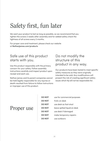
Safety first, fun later
We want your product to last as long as possible, so we recommend that you tighten the screws 2 weeks after assembly and for added safety check the tightness of all screws every 2 months.
For proper care and treatment, please check our website at NathanJames.com/products
Safe use of this product starts with you.
Use this product responsibly with the primary concern for your safety. Follow assembly instructions carefully and inspect product upon receipt and each use.
Nathan James and its parent companies cannot be held legally responsible for any injuries or death resulted from failure to follow instructions or improper use of this product.
Do not modify the structure of this product in any way.
Our products have been tested to meet specific safety measures as they were originally intended to be sold. Any modifications will present the risk of creating significant safety issues which NJ will not be responsible for.
DO NOT use for commercial purposes
DO NOT frolic on desk
DO NOT use desk as foot stool
Proper use
DO NOT leave spilled liquid on desk
DO NOT use desk if damaged
DO NOT make temporary repairs
DO NOT use outdoors