Design Guidelines GENERAL RETURNWAY LAYOUT Run Direction
Drive Shaft
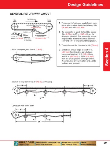
A, Vertical Sag When Running 3 in to 5 in (76 mm to 127 mm)
Detail A Entry Direction Detail A - Minimum radius of 6 in (153 mm)
* Be Sure To Break Ends of Returnway
D, Horizontal Span 18 in to 24 in (457 mm to 610 mm)
Short conveyors [less than 6’ (1.8 m)]
A - The amount of catenary sag between each set of return rollers should be between 3 in. (76 mm) and 5 in. (127 mm). B - If a snub roller is used, it should be placed 9 in. (0.23 m) to 18 in. (0.46 m) from the drive and idle shaft. The snub roller should be placed so that the chain has between 150° and 180° of wrap around the sprocket. C - The minimum roller diameter is 3 in.(76 mm) D - Slide beds should begin at least 18 in. (457 mm) from the drive sprockets on conveyors less than 12 ft. (3.6 m) long and 24 in. (610 mm) to 48 in. (914 mm) from the drive sprocket on longer chains. A combination of return rollers and a slide bed can also be used.
Section 4
Idle Shaft
Medium to long conveyors [6’ (1.8 m) and longer]
Conveyors with slider beds
29