5400 Series Low Air Inclusion Refrigerant Assembly Instructions/Component Part Numbers
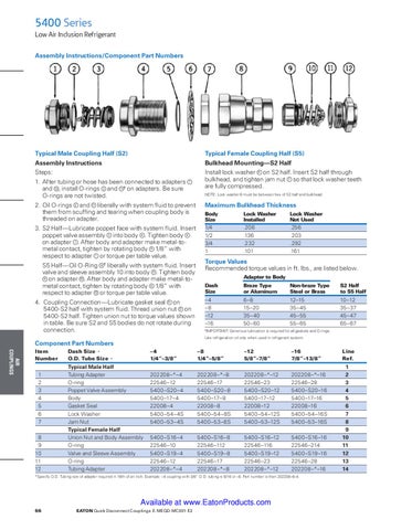
Typical Male Coupling Half (S2)
Typical Female Coupling Half (S5)
Assembly Instructions
Bulkhead Mounting—S2 Half
Steps: 1. After tubing or hose has been connected to adapters and 12 , install O-rings 2 and 11 † on adapters. Be sure O-rings are not twisted.
1
Install lock washer 6 on S2 half. Insert S2 half through bulkhead, and tighten jam nut 7 so that lock washer teeth are fully compressed. NOTE: Lock washer 6 must be between hex of S2 half and bulkhead.
2. Oil O-rings 2 and 11 liberally with system fluid to prevent them from scuffing and tearing when coupling body is threaded on adapter.
Maximum Bulkhead Thickness Body Size
Lock Washer Lock Washer Installed Not Used
3. S2 Half—Lubricate poppet face with system fluid. Insert poppet valve assembly 3 into body 4 . Tighten body 4 on adapter 1 . After body and adapter make metal-tometal contact, tighten by rotating body 4 1/8” with respect to adapter 1 or torque per table value.
1/4 1/2 3/4 1
.206 .136 .232 .101
S5 Half—Oil O-Ring 9 † liberally with system fluid. Insert valve and sleeve assembly 10 into body 8 . Tighten body 8 on adapter 12 . After body and adapter make metal-tometal contact, tighten by rotating body 8 1/8” with respect to adapter 12 or torque per table value. 4. Coupling Connection—Lubricate gasket seal 5 on 5400-S2 half with system fluid. Thread union nut 8 on 5400-S2 half. Tighten union nut to torque values shown in table. Be sure S2 and S5 bodies do not rotate during connection.
Torque Values Recommended torque values in ft. lbs., are listed below. Adapter to Body Dash Size
Braze Type Non-braze Type or Aluminum Steel or Brass
S2 Half to S5 Half
–4 –8 –12 –16
6–8 15–20 35–40 50–60
10–12 35–37 45–47 65–67
12–15 35–45 45–55 55–65
IMPORTANT: Generous lubrication is required for all gaskets and O-rings.
†
Use refrigeration oil only when used in refrigerant system.
Component Part Numbers AIR COUPLINGS
Item Dash Size→ Number O.D. Tube Size→
1 2 3 4 5 6 7 8 9 10 11 12
.256 .203 .292 .161
Typical Male Half Tubing Adapter O-ring Poppet Valve Assembly Body Gasket Seal Lock Washer Jam Nut Typical Female Half Union Nut and Body Assembly O-ring Valve and Sleeve Assembly O-ring Tubing Adapter
–4 1/4”–3/8”
–8 1/4”–5/8”
–12 5/8”–7/8”
–16 7/8”–13/8”
202208–*–4 22546–12 5400–S20–4 5400–17–4 22008–4 5400–54–4S 5400–53–4S
202208–*–8 22546–17 5400–S20–8 5400–17–8 22008–8 5400–54–8S 5400–53–8S
202208–*–12 22546–23 5400–S20–12 5400–17–12 22008–12 5400–54–12S 5400–53–12S
202208–*–16 22546–28 5400–S20–16 5400–17–16 22008–16 5400–54–16S 5400–53–16S
5400–S16–4 22546–10 5400–S19–4 22546–12 202208–*–4
5400–S16–8 22546–112 5400–S19–8 22546–17 202208–*–8
5400–S16–12 22546–116 5400–S19–12 22546–23 202208–*–12
5400–S16–16 22546–214 5400–S19–16 22546–28 202208–*–16
*Specify O.D. Tubing size of adapter required in 16th of an inch. Example: –4 coupling with 3/8” O.D. tubing is 6/16 or –6. Part number is then 202208–6–4.
Available at www.EatonProducts.com 66
eaton Quick Disconnect Couplings E-MEQD-MC001-E2
Line Ref.
1 2 3 4 5 6 7 8 9 10 11 12 13 14