INDIANINSTITUTEOFENGINEERINGSCIENCE ANDTECHNOLOGY,SHIBPUR
Aminiprojecton“DESIGNOFTRANSMISSIONLINETOWER”
Underthesupervisionof“Prof.AparnaDeyGhosh” by
MrinmoySaha (2024CEM022)
DepartmentofCivilEngineering
Specialization:StructuralEngineering
MasterofTechnology
1st Year-1st Semester
A.INTRODUCTION
Atransmissionlinetower(orpylon,electricitypylon,hydrotower)isatallstructure.Itismadeofsteel lattices. It is usually used to carry high voltage. It is a medium that provides electric power from generatingstationstoelectricalsubstations.[1]
Thetransmissionlinetowersarecategorisedinfourcategories-
1. Thesuspensiontowers.
2. Thedead-endterminaltowers.
3. Thetensiontowers.
4. Thetranspositiontowers.
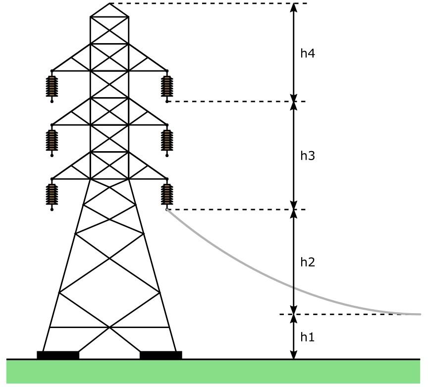
The height of a transmission line tower is generally between 15m-55m (49-180 ft). When a longer-span transmission tower is needed, then the taller tower willbeconstructed.Thefactorsthataffecttheheight oftransmissiontowersare[2]-
I. Minimumpermissiblegroundclearance(h1)
II. Maximumsag(h2)
III. Verticalspacingbetweenthetopandbottom conductors(h3)
IV. Verticalclearancebetweenthegroundwire andtopconductor(h4).
V. Totalheightofthetower(h)=h
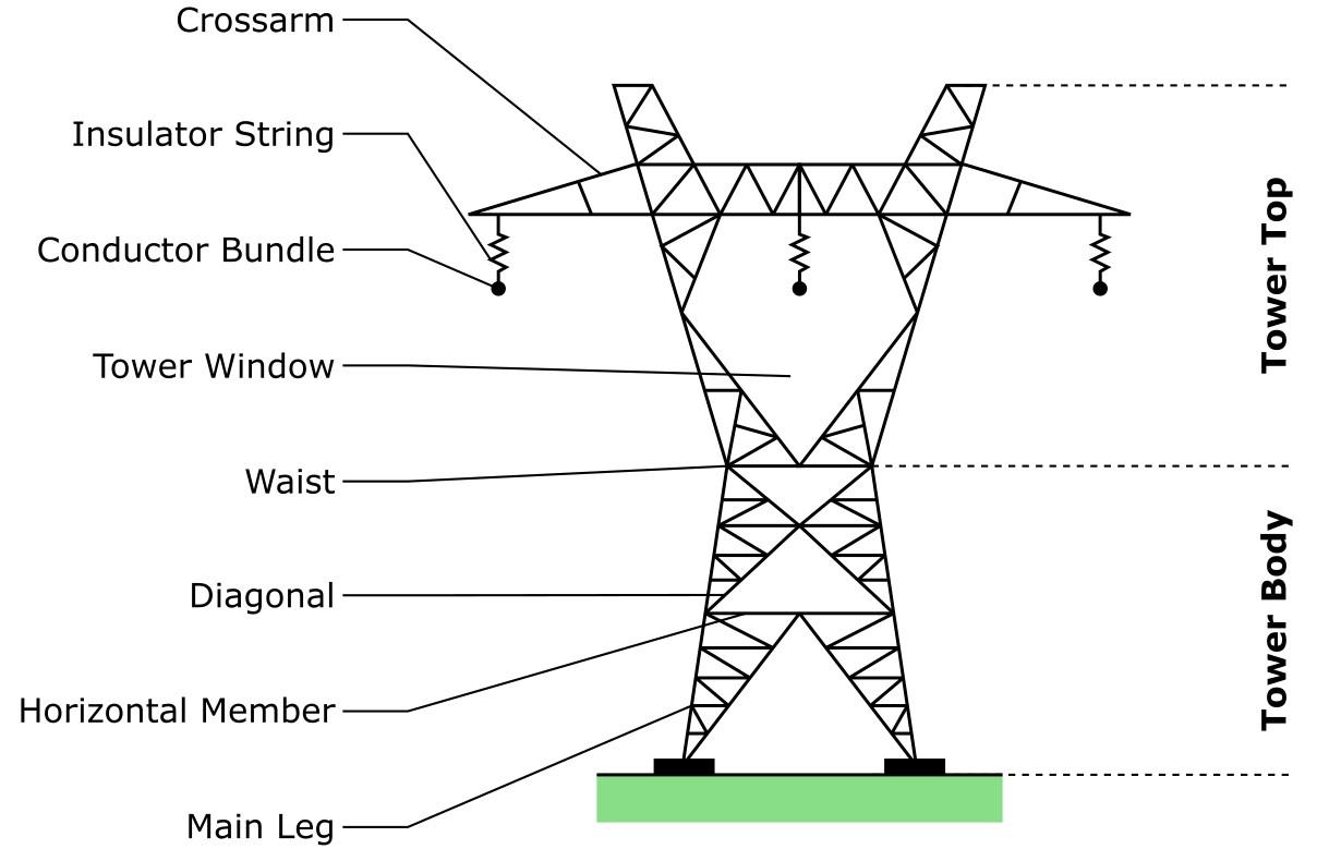
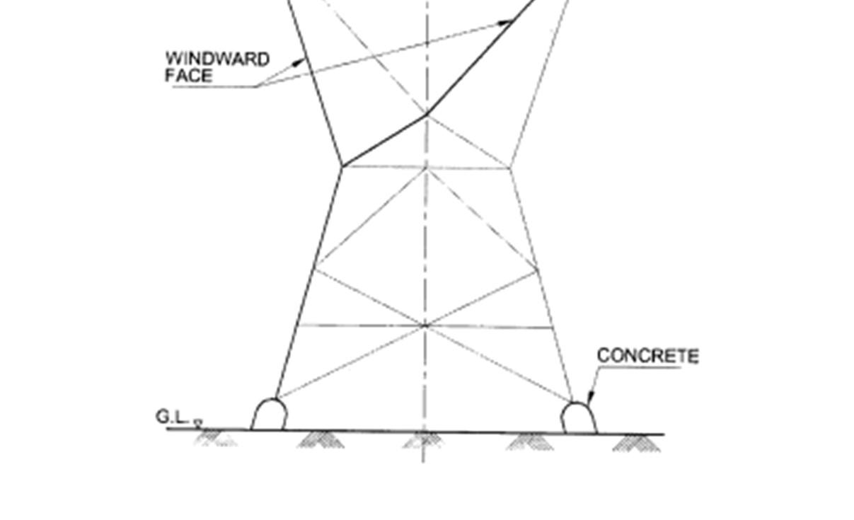
Atransmissiontowerhasthreemainparts-
a. Towertop
b. Waist
c. Towerbody
Further, these 3 parts are divided into many sub-parts.Thereare-
a. Towertop-
i) Crossarms
ii) Insulatorstring
iii) Conductorbundle
iv) Towerwindow
Fig-1:TransmissionTowerStructure[3]
Fig-2:PartsofTransmissionTower[4]
b. Towerbody-
i) Diagonal
ii) Horizontalmembers
iii) MainLeg
Thetransmissionlinetowersaregenerallymadeoftubularsteels,lattices(steeloraluminium), woodandconcrete.
Generally,thetransmissiontowerissubjectedtothefollowingloads:
Deadloadoftower.
Deadloadfromconductorsandotherequipment.
Loadfromsnowonconductorsandequipment.
Snowloadonthe toweritself.
Windloadonthetower.
Windloadonconductorsandequipment.
Erectionandmaintenanceload.
Loadsfromconductorstensileforces.
Seismicload.
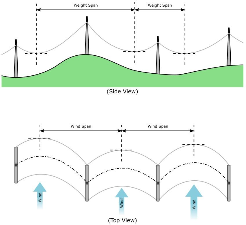
The conductors are the main load source on a transmission tower, acting like chains that can only withstandtensilestresses.Asaresult,theso-called"weight span"—which may differ significantly from the "wind span"usedinconjunctionwiththewindloadcalculation— is used to compute the dead load from the conductors.
Figure3:WindLoadsandWeight[6]Typically,anaverage span lengthof300to 450metersisselected. The presence of ice, snow, etc. increases the weight of the covered sections and makes them more vulnerable to wind-related damage. Transmission tower damage and collapse have oftenresultedfromundervaluingthesefactors.Theamount andpatternofsnowandice.[5]
Fig-3:WeightandWindLoads[6]
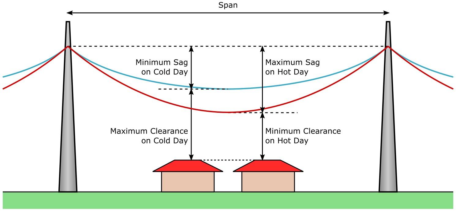
From the mechanical point of view, the conductors act like wires whose sag between two supports depends onthe temperature and pretensioning of the wires. When the temperature is low the
DesignofTransmissionLineTowers
Fig-4:Saggingdifferenceduetotemperaturechanges[7]
sag will be minimum and when the temperature is high the sag will be maximum. The tensile forces duetothesaggingofwiresplayabigroleinstructuraldesign.
Theconfigurationof aself-supportedsteellatticetowerisdependentonvariouselectricaland structuralrequirementssuchas-
1. Conductorarrangement
2. Minimumgroundclearance
3. Lengthofinsulatorassembly
4. Theairgapclearances
5. Mid-spanclearancesbetweenconductorandgroundwire
6. Natureofshieldingprovided,thatis,thenumberandheightofgroundwires
7. Thesystemofbracingpatterns
All the above factors are therefore to be considered from transmission efficiency, structural soundnessandpersonnelsafetypointofview.[8]
Herearesomeotherthingstoconsiderwhendesigningatransmissionlinetower:
Tower height: The user specifies the tower's height, and the structural designer then designsthetower'sconfiguration,members,andjointdetails.
Foundation: The tower's foundation is usually designed for compressive loads, but it may also need to withstand uplift and tilting forces.The type of foundation used dependsontheexpected upliftandlateralforces.
Windloads:Windloadsontheconductorandgroundwirecanbecalculatedusingthe formula Fwc = Pd × Cdc × L × D × GC
Where,
Fwc = wind load on conductor; Pd = design wind pressure; Cdc = drag coefficient for ground wire (=1.2 drag coefficient for conductor = 1.0); L = wind span; d = diameter of conductor/ground wire; Gc = gust response (3.4)
SomeNotableElectricTransmissionLineTowersinIndia:[9]
HooglyRiverCrossing 1932 WestBengal DiamondHarbor 236m
TistaRiverCrossing 1985 WestBengal Jalpaiguri 120m
SoneRiverCrossing 1983 UttarPradesh SoneBhadra 96m
B. SOME IMPORTANT CODALPROVISIONS [IS 802 (Part 1/ Section 1): 2015]
B0.SomeTerminologiesUsedinTheDesignofTransmissionLines[10]
Return Period: The number of years, reciprocal of which gives the probability of extreme windexceedingagivenwindspeedinanyoneyear.
Reliability: Reliability of a transmission system is the probability that the system would perform its function/task under the designed load conditions for a specified period. In simple terms, the reliability may be defined astheprobabilitythat a given item will indeed survive a givenserviceenvironmentandloadingforaprescribedperiodoftime.
Security: The ability of a system to be protected from any major collapse such as cascading effect, if a failure is triggered in a given component. Security is a deterministic concept as opposedtoreliability,whichisprobabilistic.
Safety: The ability of a system not to cause human injuries or loss of life. It relates, in this standard,mainlytoprotectionofworkersduringconstructionandmaintenanceoperations.
Tangent Tower: Also known as ‘suspension tower’or ‘straight line tower’. Conductors on thesetowersaresupportedbymeansofI-strings,V-strings,oracombinationofIandVstrings.
AngleTower:Theseareusedatlocationswherethereissameangleofdeviation.Thesetowers are further classified based on different deviation angles. These towers are also known as ‘tensiontower’asconductorsaregenerallysupportedwithtensioninsulatorsonthesetowers.
SuspensionInsulatorString:I,VorYtypeinsulatorstringsuspendedontangent/suspension/ straight-runtower.Onthisstring,conductorissuspendedfromacross-arm.
Tension InsulatorString: This string is used on tension/section/angle/dead end towers. It is providedonbothsideoftowerinthedirectionofconductor.
B1.ReliabilityConsiderations[11]
Transmissionlinesshallbedesignedforthereliabilitylevelsgiveninbelowtable.Theselevels areexpressedintermsofreturnperiodsinyearsofclimatic(wind)loads.Theminimumyearly reliabilityPs,correspondingtothereturnperiod,Tisexpressedas: Ps = (1 – 1/2T)
TableofReliabilityLevelsofTransmissionLines
Description
Returnperiodofdesignloads,inyears, T
Reliabilitylevel1shallbeadoptedforEHVtransmissionlinesupto400kVclass.
Reliabilitylevel2shallbeadoptedforEHVtransmissionlinesabove400kVclass.
Reliability level 3 shall be adopted for tall river crossing towers and special towers, although thesetowersarenotcoveredinthisstandard.
B2.WindEffect[12]
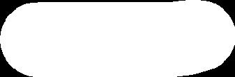
1. BasicWindSpeed(VB)
Figure 5 shows thebasic wind speed map of India as applicable at 10 m height above mean ground levelforthesixwindzonesofthecountry.BasicwindspeedVB isbasedonpeakgustSpeedaveraged overashorttimeintervalof about3s,correspondstomeanheights above groundlevelin openterrain (Category2)andhasbeenworkedoutfor50yearsreturnperiod[seeIS875(Part3)].
Basicwindspeedsforthesixwindzones(seeFig.5)are:
WindZone
BasicWindSpeed(VB m/s) Zone-1
Zone-5
Zone-6
Notes:
50m/s
55m/s
ReferencemaybemadetoIS875(Part3)forbasicwindzonemaps.
Incasethelinetraverseson theborderofdifferent windzones,the higher windspeedmaybe considered.
2. MeteorologicalReferenceWindSpeed(VR)
It is the extreme value of wind speed over an over-ageing period of 10 min duration and is to be calculatedfrombasicwindspeed,VB bythefollowingrelationship:
VR = VB / K0
Where,K0 isafactortoconvert3speakgustspeedintotheaveragespeedofwindduring10minperiod atalevelof10maboveground.K0 maybetakenas1.375.
3. DesignWindSpeed(Vd)
Thereferencewindspeedobtainedshallbemodifiedto includethefollowingeffectstogetthedesign windspeed:
RiskCo-efficient
The table below gives the risk coefficient values K1 for different wind zones for the three reliability levels.
Tableofriskco-efficientK1 fordifferentreliabilitylevelsandwindzones
ReliabilityLevel
Co-efficient,K1 forWindZones
TerrainRoughnessCo-efficient(K2)
Below table gives the values of coefficient K2 for the three categories of terrain roughness correspondingto10minaveragedwindspeed.
TableofTerrainroughnessco-efficient,K2
TerrainCategory 1 2 3
Co-efficient,K2 1.08 1.00 0.85
Note- For lines encountering hill/ridges, the value of K2, for a given terrain shall be changed to next highervalueofK2.
4. TerrainCategories:
Category-1:Exposedopenterrainwithfewornoobstructionandinwhichtheaverageheight ofanyobjectsurroundingthestructureislessthan1.5m.
NOTE — This category includes open seacoasts, open stretch of water, deserts and flat treeless plains.
Category- 2: Open terrain with well scattered obstructions having height generally between 1.5mand10m.
NOTE—Thiscategoryincludesnormalcountrysideswithveryfewobstacles
Category-3:Terrainwithnumerouscloselyspacedobstructions
NOTE—Thiscategoryincludesbuiltupareasandforestareas.
5. TopographyFactor(K3)
Thebasic windspeed Vd takesinto accountthe generallevelofthesiteabove sealevel.Thisdoesnot allow for local topographic features such as hills, valleys, cliffs, escarpments, or ridges which can significantlyaffectwindspeedintheirvicinity.Theeffectoftopographyistoacceleratewindnearthe summitsofhillsorcrestsofcliffs,escarpmentsorridgesanddeceleratethewindinvalleysornearthe footofcliffs,steepescarpments,orridges.
Theeffectoftopographyshallbesignificantatasitewhentheupwindslope(θ)ismorethanabout 3°, and below that, the value of k3 may be takento be equal to 1.0. The value of k3 is confined in the range of 1.0 to 1.36 for slopes more than 3°. It may be noted that the value of k3 varies with heightabovegroundlevel,atamaximumneartheground,andreducingto1.0athigherlevels.
6. ImportanceFactorforCyclonicRegion(K4)
The east coast of India is relatively more vulnerable for occurrences of severe cyclones. On the west coast, Gujarat is vulnerable for severe cyclones. Studies of wind speed and damage to buildings and structurespointtothefactthatthespeedsgiveninthebasicwindspeedmapareoftenexceededduring thecyclones.Theeffectofcyclonicstormsislargelyfeltinabeltofapproximately60kmwidthatthe coast.Inordertoensurebettersafetyofstructuresinthisregion(60kmwideontheeastcoastaswell
as on the Gujarat Coast), the following values of k4 (as recommended in IS 15498) are stipulated as applicableaccordingtotheimportanceofthestructure:
Structures of post-cyclone importance for emergency services (such as cyclone shelters,hospitals,schools,communicationtowers,etc.)
7. DesignWindPressure(Pd)
The design wind pressure on towers, conductors and insulators shall be obtained by the following relationship:
Where,
Pd =designwindpressure,inN/m²;
Vd =designwindspeed,inm/s.
Design windpressures, Pd for thethree reliability levels and pertaining to six wind zones and thethreeterraincategorieshavebeenworkedoutandgiveninbelowtable.
B3.LOADSONTOWERS[14]
1.ClassificationofLoads:
Transmission lines are subjected to various loads during their lifetime. These loads are classified into three distinctcategories,namely,
a) Climatic loads, related to the reliabilityrequirements.
b) Failure containment loads, related tosecurityrequirements.
c) Construction and maintenance loads,relatedtosafetyrequirements.
ClimaticLoad
These are random loads imposed on tower, insulator string, conductor and ground wire/OPGW due to action of wind on transmission line and do not act continuously. Climatic loads shall bedeterminedunderthe followingclimaticconditions,whicheverismorestringent:
Fig-6:HorizontalConfigurationTower[15]
a) 100% design wind pressure at everyday temperature, [(Pd) for transverse windand(Pd X sin²Ω)for obliquewind],
b)75%designwindpressureateverydaytemperature,
c)36%designwindpressureatminimumtemperature.
NOTES
1Criterion(b)istobeadoptedforalltowersundersecuritycondition.
2 Criterion (c) is normally not crucial for tangent tower but shall be checked for angle or dead-end towers,particularlyforshortspans.
FailureContainment Loads,RelatedtoSecurityRequirements
Theseloadscompriseof,
A)Anti-CascadingLoads;
B)TorsionalandLongitudinalLoads;and
C)NarrowFrontWindLoads.
A.Anti-CascadingLoads
Cascadefailuremaybecausedbyfailureofitemssuchasinsulators,hardware,joints,failuresofmajor componentssuchastowers,foundations,conductorduetodefectivematerialorworkmanshiporfrom climaticoverloadsorsometimesfromcasualeventssuchasmisdirectedaircraft,avalanches,sabotage, etc.Thesecuritymeasuresadoptedforcontainingcascadefailuresinthelineistoprovideangletowers atspecificintervalswhichshallbecheckedforanti-cascadingloads.
B.TorsionalandLongitudinalLoads
Theseloadsarecausedbybreakageofconductors)and/orgroundwire/OPGW.Allthetowersshallbe designedfortheseloadsforthenumberofconductor(s)and/orgroundwire/OPGWconsideredbroken.
C.NarrowFrontWindLoads
Onlysuspensiontowersaretobedesignedunderthiscondition.Theseloadsarecausedbyhigherwind Speedinnarrowwidth acting on tower andinsulator andnowindis consideredactingonwiresunder thiscondition.
ConstructionandMaintenanceLoads,RelatedtoSafetyRequirements
Theseareloadsimposedontowersduringconstructionandmaintenanceoftransmissionlines.
C.LITERATUREREVIEW
Shukla and Selvaraj (2017) studied the plot demonstrated a relationship between structural analysisandthereal-worldbehaviouroftowersandconfirmedthatsoftwarecanaccuratelypredicthow members would behave when loads are applied. The real forces in each member are somewhat lower than the software-calculated values. For this reason, the software analysis can completely rely on the design. Despite these outcomes, there have been numerous instances where testing has failed—either totallyorpartially.
Pandiyan,PeterandKannan(2018)studiedacomparisonofthecircularhollowsection'sweight while they are the same in height, bracing, and 220KV power tower, the rolled steel section was less noticeable.IntheFuturehollowsectionsmightprovideausefuloptimizingdesignbasedontheweight andefficiencyof different bracingsystems andtower height. Consequently, thetabular columnabove displaysthecomparisonoftheweightofdifferenttubularsectionsofstructuralsteeldimensions.
Chyrmang and K (2020) observed that when employing an X bracing tower instead of a K bracingtower,3.07%lesssteelweightwasused.TheconclusionisthatXbracingislessexpensivethan
Kbracing.Forbothbracingsystems,theBaseShearoftheTowersforWindZones2and6ofSeismic ZoneVis72.2%higherthantheSeismicZoneII.Underallloadingscenarios,thereislittle difference in the deflections of any bracing system. Therefore, in practical terms, it can be advised. Whenconsideringearthquakeloading,allofthedeflectionsarewithinallowableboundsiftheyareless than Dmax = 0.005*H, where Dmax is the greatest lateral deflection and H is the height of the structure above the base. All the deflections for Wind loading are in permissiblelimitsarelessthanH/100.
Quddus, Riyan andAnwar (2018) observed that the steel that is utilized in transmission line towersisprimarilytheleastamountofsteelthathasthebeststructuralfitfor220KVlinetowers.
Sonowaletal.(2015)concludedthatthemanualanalysisofastaticallyindeterminatestructure, such as a transmission line tower, is exceedingly intricate. For this issue any software can help in analysis.
Punse(2014)observedthattheperformanceofanarrow-basedsteellatticetransmissiontower structureiscrucial,particularlyundereccentricloadingconditionsathighaltitudescomparedtonormal towers.This specific type of tower can effectively withstand design wind loads and actual loads.The lower tier members playa significant role in handlingaxial forces, while themembers supporting the cableshavealocalizedimpact.Verticalmembersbearmoreloadthanhorizontalanddiagonalmembers, andtheonessupportingcablesathigherelevationsgreatlyinfluencethetower'sbehaviour.Thetwisting momentoftheintactstructurehasminimaleffect.Bytreatingthetower'sgeometryparametersasdesign variables,substantial weight reductioncanbeachievedthrough geometrychanges.Towers withangle sectionsandX-bracingexperiencegreaterweightreductionafteroptimization,whiletubesectionsare notcost-effectiveforthistypeoftower.Thetotalweightofthetower,includingnutbolts,anchorbolts, hardware,etc.,rangesfrom30to35tones.
Reddy et al. (2018) observed that the utilization of Triangular Base Self-Supporting Tower resultsina9.23%reductionintheweightofstructuralsteel.Additionally,theuseofSquareBaseGuyed Mastresultsina 39.96%decreasein structuralsteel (excludingguyropes),directlytranslatingto cost savingsineachtowerorthestructuralenhancementofthetransmissionline.
Srikanth and Satyam (2014) observed that in their current study involves analysing various loads, including vertical, lateral, and longitudinal loads, based on Indian standards. The critical combination of forces in the structure is the breaking load. Research on transmission towers has indicatedthatthefailureoflegmembersincreasesthestructure'svulnerabilitytodamage.Theanalysis revealed that the maximum axial force in the leg members is 1600kN when considering the breaking load combination, while it reduces to 522.382kN without considering breaking load. Assuming the tower is in the central span of equal distances between adjacent towers, the breaking load is not the
primary design criterion for elements. Despite conducting dynamic analysis, wind remains the predominantloadonthesetallstructures.
Modani and Warade (2024) observed that the utilization of STAAD. Pro for the analysis and design of transmission towers presents numerous benefits. This software offers precise structural analysiscapabilities,enablingengineerstomodelandevaluateintricatetowerstructuresunderdifferent loads and conditions. The automated design optimization features assist in enhancing the design for cost-efficiencyandadherencetodesigncodesandstandards.Theuser-friendlyinterfaceandadvanced modelling tools improve productivity, while the visualizations and documentation capabilities contribute tobetter comprehension, communication, and compliance. Overall, STAAD. Pro proves to bearobusttoolthatstreamlinestheefficientanddependableanalysisanddesignoftransmissiontowers, resultinginsecureandcost-efficientstructures.
Mohite, Patil and Shetti (2019) observed that the steel transmission tower was studied for different riskcoefficients withthe same bracing system in Pune andDelhi, considering seismic zones IIIandIV.Theanalysisofthesteeltransmissiontowerswascarriedoutusingversion20oftheSAP2000 Integrated Solution for StructuralAnalysis and Design Software. Based on the research and analysis usingthe same software, the following conclusions were drawn, confirmingthe safety of thetowerat bothlocations:1)Thereisasignificantdifferenceinthebendingmomentforcesonthemembersatthe twospecifiedlocationsduetoslightchangesinwindpressure,buttheyremainwithinsafelimits,with themaximumforce observedon member no.4.2)The axial force inthe membersofthe transmission tower shows a substantial change between the two locations, with the maximum axial force observed onmemberno.4and40.3)Thereisaslightchangeinshearforce.4)Thebasereactionishigherinthe Delhi steel transmission tower compared to the Pune steel transmission tower. Further studies can exploredifferentseismiczones,bracingsystems,andriskcoefficients.
ObservationsfromLiteratureReview:
Hollowsectionscouldoptimizedesignbasedonbracingefficiencyandtowerheight.
Xbracing towersareless expensivethanKbracing towershigherBaseShear in Wind Zones2and6ofSeismic ZoneV.Deflectionsofanybracingsystemaresimilarunder all loading scenarios, with allowable bounds for earthquake loading and permissible limitsforwindloading.
The manual analysis of a statically indeterminate structure, such as a transmission line tower, isexceedinglyintricate.
A narrow-based steel lattice transmission tower structure is crucial for withstanding wind loads and actual loads at high altitudes. It can handle axial forces, vertical
members, and cablesathigherelevations.Geometryparameterscan be usedtoreduce weight,withanglesectionsandX-bracingachievinggreaterreduction.
TheTriangularBaseSelf-SupportingTowerandSquareBaseGuyedMastsignificantly reduce structural steel weight, leading to cost savings and structural enhancement in transmissionlinestructures.
Indian standards for various loads, focusing on breaking load. Transmission towers' failureincreasesvulnerabilityto damage.Themaximumaxial forcein leg membersis 1600kN when considering breaking load, but wind remains the predominant load on tallstructures.
D.DESIGNANDANALYSISOFTHEMODELUSINGSAP2000
D1.ModelDescription[16]:
TotalHeight: 30m
Distancebetweentwotowers: 50m
MaterialUsed: Steel
YieldStrengthofSteel(Fy): Fe345
SectionUsed: ISA200200
StructureType: LatticeType
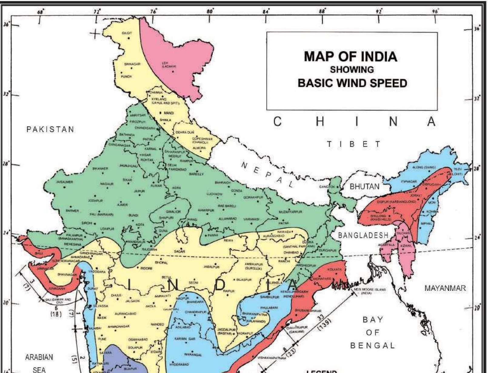
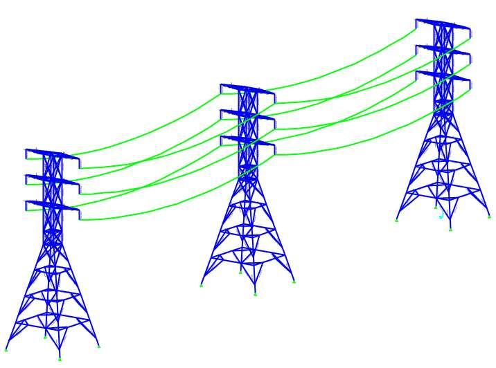
Fig7:ArrangementofModel
D2.SectionProperty[17]
Designation ISA200200
Size 200mmx200mm
Thickness(t) 25mm
SectionArea(a) 93.80cm2
WeightperMeter(w) 73.60kg
CentreofGravity(Cxx=Cyy) 5.88cm
DistanceofExtremeFibre(exx=eyy) 14.12cm
ProductofInertia(Ixy) 2015.7cm4
RadiusatToe(r2) 10mm
RadiusatRoot(r1) 15mm
ModulusofSection(Zzz=Zyy) 243.3cm3
RadiiofGyration(rxx=ryy) 6.05cm
RadiiofGyration(ruu) 7.63cm
RadiiofGyration(rvv) 3.88cm
MomentofInertia(Ixx=Iyy) 3436.3cm4
MomentofInertia(Iuu) 5460.9cm4
MomentofInertia(Ivv) 1411.6cm4
D3.LoadDescription:
WindloadappliedalongXandYdirectionsandtheconditionsandvaluesaregivenbelow:
CodeFollowed: IS-875(Part3):2015
Location: Kolkata
WindZone: ZoneV(fromFig5)
WindSpeed: 50m/s
ReliabilityLevel: 2
ExposureandPressure Condition ExposurefromArea Objects
TerrainCategory:(K2) Category3(K2=0.85)
RiskCo-efficient:(K1) 1.13
TopographyFactor:(K3) 1.00
ImportanceFactorforCyclonicRegion(K4) 1.30
D4.DesignSpeedandDesignWindPressure Calculation
D5.Result:
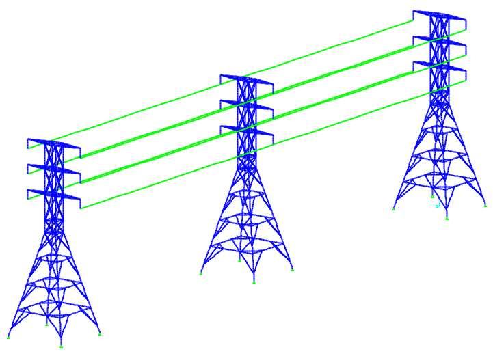
Fig9:TensionedCable
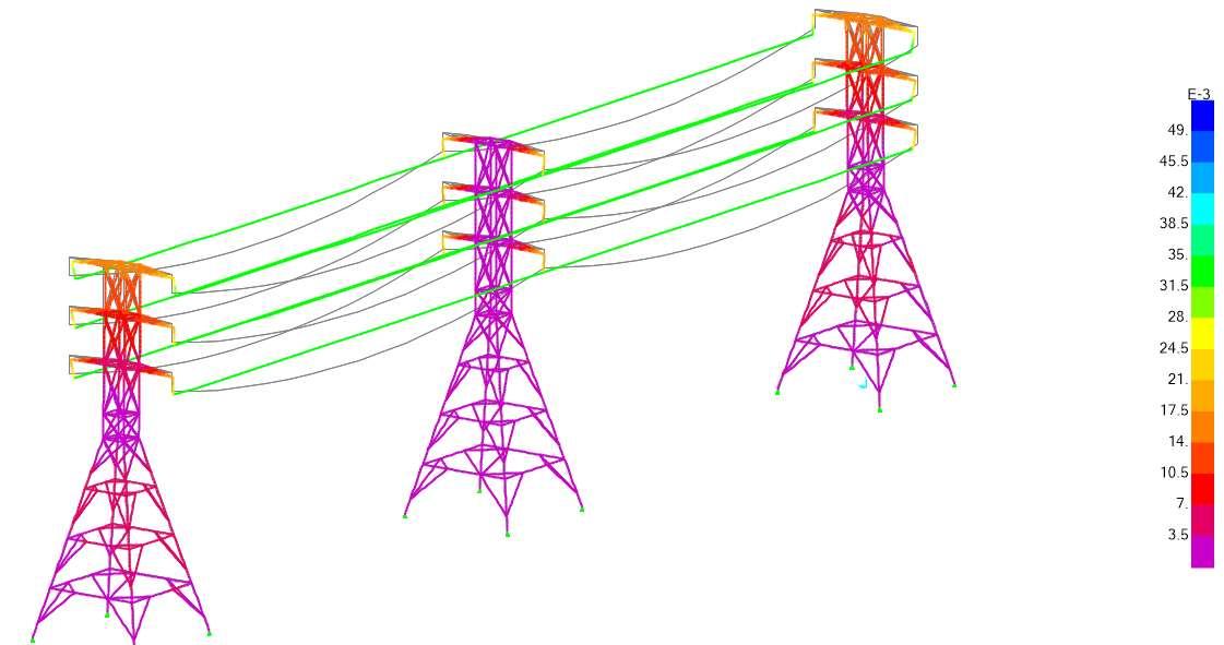
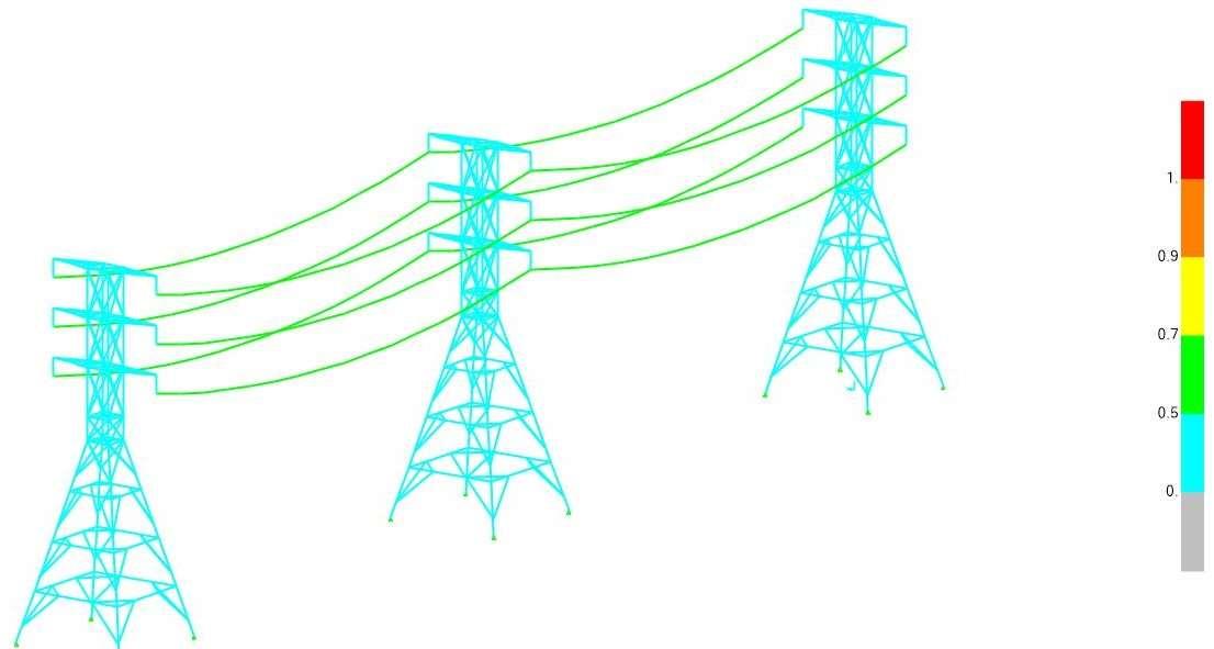
Fig10:ResultantStressColourContourBefore SteelDesign
DesignofTransmissionLineTowers
Fig11:ResultantStressesContour AfterSteelDesign
G.CONCLUSION
The design result displays the structure is safe under the wind load, extreme wind speed condition at coastal region. The result of SAP2000 analysis can be matched with the real time project. The transmission line tower structure can be mainly failed in wind load as well as breaking force of insulators. The analysis is done on wind load analysis. In future the analysis can be done by the combinationofwindloadandbreakingforceofinsulators.
F.LISTOFABBREVIATIONS
1. IS-IndianStandards
2. EHV-ExtraHighVoltage
3. OPGW-OpticalGroundWire
4. ISA-IndianSteelAngle
G.REFERENCES
[1]&[9]Wikipedia-https://en.wikipedia.org/wiki/Transmission_tower#
[2] & [3] & [4] & [5] & [6] & [7] Savree- https://www.savree.com/en/encyclopedia/electricaltransmissiontowers#:~:text=Transmission%20Tower%20Structures,guyed%20(supported%20by%20cables)
[8]N.B.Mishra(1979).AnalysisandDesignofTransmissionLineTowers.ADissertationSubmitted inPartialFulfillmentofTheRequirementsforTheAwardofTheDegreeofMasterofEngineeringIn WaterResourcesDevelopment.
http://shodhbhagirathi.iitr.ac.in:8081/jspui/image/pdf/web/viewer.html?file=/jspui/bitstream/12345678 9/4104/1/WRDM175686.pdf
[10]& [11]&[12] &[14]IndianStandardCode ofUse of Structural Steel inOverheadTransmission LineTowers—CodeofPractice- Part1:Materials,LoadsandDesignStrengths-Section1:Materials andLoads(FourthRevision)-IS802(Part1/Section1):2015
[13]IS875(Part3):2015,Figure-01,Pageno-06
[15]IS802(Part1/Section1):2015,Figure-03,Pageno-08
[16]YouTube Channel- Decode BD:TransmissionTower Design withWind Loading & Cable Effect inSap2000.https://www.youtube.com/watch?v=_Z3hBz9tFeU
[17]ISSP:6(1)-1964,Table-III,Pageno-10
[18]FailuresofTransmissionLineTowers-CommitteeReports:G.O.I.:MinistryofPowers-Centra ElectricalAuthority(C.E.A.). h ps://cea.nic.in/failure-type/failures-of-transmission-linetowers/?lang=en
VeerendraKumar Shukla and M. Selvaraj(2017).Assessment of StructuralBehavior ofTransmission Line Tower using Strain Gauging Method. International Journal of Steel Structures 17(4): 1529-1536 (2017).https://link.springer.com/content/pdf/10.1007/s13296-017-1220-y.pdf
AravindPandiyanA.,JohnPeterS.,andKamalaKannanP.(2018).ComparativeAnalysisandDesign ofTransmissionLineTowerUsingSteelSectionwithTubularSection.InternationalResearchJournal ofInnovationsinEngineeringandTechnology(IRJIET).
https://irjiet.com/common_src/article_file/1564495939_de42609f71_2_irjiet.pdf
Sniawlangki T Chyrmang, Prof. Geetha K (2020). Analysis of Transmission Tower. International ResearchJournalofEngineeringandTechnology(IRJET).https://www.irjet.net/archives/V7/i8/IRJETV7I887.pdf
Mohd Abdul Quddus, Mohd Riyan, Dr. Mohd Farrukh Anwar (2018). Analysis And Design of Transmission Line Towers in Comparison with WindAnalysis. International Journal of Management, TechnologyandEngineering.https://www.ijamtes.org/gallery/3-.pdf
D.B. Sonowal, J.D. Bharali, M.K.Agarwalla, N. Sarma, P. Hazarika (2015).Analysis and Design of 220kVTransmissionLineTower(AconventionalmethodofanalysisandIndianCodebasedDesign).
IOSR Journal of Mechanical and Civil Engineering (IOSR-JMCE). https://www.iosrjournals.org/iosrjmce/papers/NCIEST/Volume%201/08.40-49.pdf
Gopi Sudam Punse (2014). Analysis and Design of Transmission Tower. International Journal of ModernEngineeringResearch(IJMER).https://www.ijmer.com/papers/Vol4_Issue1/AP41116138.pdf
T.AbhiramReddy,K.Murali,DSVSMRK.Chekravarty,P.AnilSagar(2018).Analysisand EconomicalDesignofTransmissionLineTowersofDifferentConfigurationsSubjectedtoWind Load.InternationalJournalofCivilEngineeringandTechnology(IJCIET). https://iaeme.com/MasterAdmin/Journal_uploads/IJCIET/VOLUME_9_ISSUE_1/IJCIET_09_01_03 7.pdf
LingampallySrikanth,Dr.DNeelimaSatyam(2014).DynamicAnalysisofTransmissionLineTowers. International Conference on Civil Engineering and Applied Mechanics (ICCEAM) 2014 in Paris, France.
https://cdn.iiit.ac.in/cdn/web2py.iiit.ac.in/research_centres/publications/download/inproceedings.pdf.b 47454e113c618d3.50617065725f207372696b616e74682e706466.pdf
Prof. P. O.ModaniandShrikantS.Warade(2024).AnalysisandDesignofTransmissionTowerusing Staad-Pro. International Journal of Advanced Research in Science, Communication and Technology (IJARSCT).https://ijarsct.co.in/Paper15001.pdf
NitishA.Mohite,VinayakB.Patil,V.G.Shetti(2019).StructuralAnalysisofSteelTransmissionTower for different Risk Coefficients-ACaseStudy.InternationalJournalfor ResearchinApplied Science& EngineeringTechnology(IJRASET).https://www.ijraset.com/fileserve.php?FID=24632