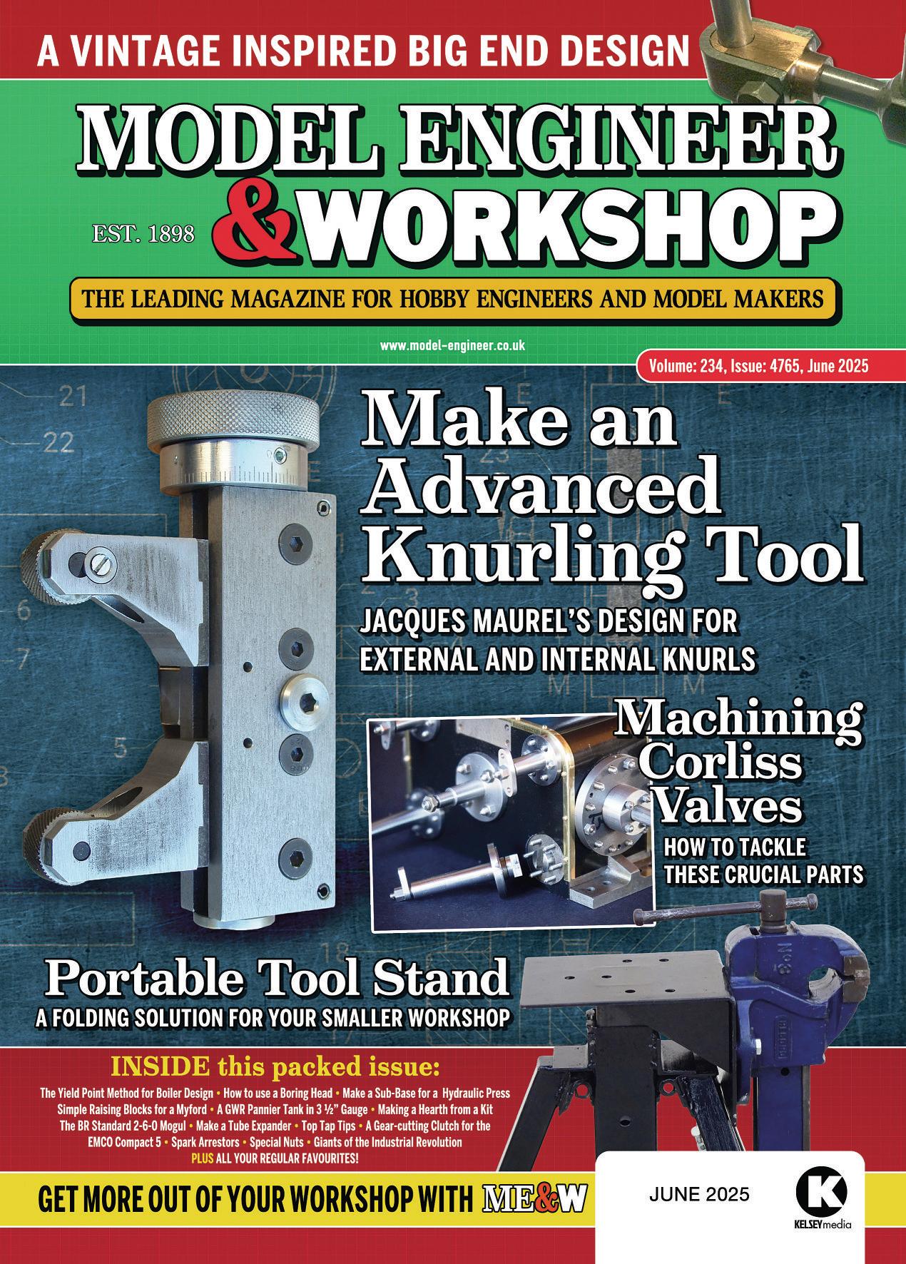











9 COVER FEATURE –A MultiPurpose KnurlingTool
This advanced knurling tool designed by Jacques Maurel is capable of both internal and external knurling.
16 The BR Standard2-6-0 Class4StandardEngine
Doug Hewson details the weighshaf forhis 5” gaugeMogul
21 Beginner’sWorkshop
Geometer gets down to the nuts and bolts of workshop practice.
22 ASub-Base fora Press Tool
Will Dogget makes an alternative base forhis hydraulic press, previously described in MEW.
26 The Yield Point Method
LesSmith and Alan Browndescribe compareyield point calculations forboiler shell thickness withthose based on ultimate tensile strength
30 Lathe Raising Blocks
MikeJospehshares his economical alternativetocommercial raising blocks.
31 Three Giants of the Industrial Revolution
MathewBolton, James Watand WilliamMurdoch arecelebrated in the heart of Birmingham.
36 End of the Big End?
ThelateDavid Fulton took inspiration from 19th century engineering to makeaspace-saving big-end bearing
37 Quick Notesfromthe Workshop
Some further tipsfor tapping small threads.
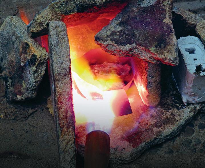
38 AFolding Stand
This space saving work stand employs avariety of atachments fordiferent tools, described by Steven Steliou.
44 ATandemCompound MillEngine
David Thomas makes the Corliss valves, the mostdistinctivefeature of this technically advanced steam engine.
51 Spark Arrestors
PeterHowell looksatthe control of sparksinhazardous areas.
55 AGWR Pannier Tank in 3½ Inch Gauge
Gerald Martyn shares the drawingsfor
his locomotive’swater pump, adesign thatcould be useful forother 3½” gaugemodels.
59 Working on the Lathe: Drilling and Boring
Neil Raine explains the use of aboring head and looksatreamers.
62 ATubeExpander
MatJefery explains his design fora tool forexpanding tubes into tubeplatesthatcan be made in awide rangeofsizes.
66 An EMCO Compact 5 Screwcuting Clutch
Graham Meek concludes his Compact 5lathe screwcuting clutch design.



70 Nowfor Something Completely Diferent
Aheron with abrokenleg maysound likea wildliferescue, butRoger Vane wasfaced with some unusual workshop challenges.
72 Book Review: Miniature Passenger Hauling Railways
RogerBackhouse reviews this new book by Paul Carpenter.
74 APrefabricated Hearth
Neil Wyat makes and uses abrazing hearth with alaser-cut kit.






















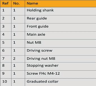
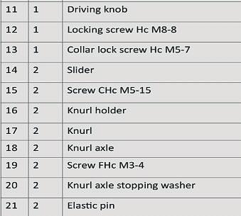
•Agraduatedcollar 10 allows an accurate control of the knurls movement thatwill be very useful to control the knurl’sdepth (for repeatable batch work) and also forthe other purposes of this tool
•The guide 2 and 3 is free to rotate around its axle 4 fora free alignment on the workpiece, the shank 1 being locked in the tool post. Thetwo pins 23 arefor limiting this rotation at rest •This type of tool is useful formaking parallel knurls as it’sdificult to adjust the cut knurling tools forstraight knurls; see my article MachiningShiny Knurls in Model Engineer 4543.
Thetool shank 1 being clamped ina toolholder,adjustthe pivot axis (part 4)tocentreheight.
Adjustthe cross slide forthe knurls axis to be in the vertical planealong the lathe’s axis.
Tightenthe knurls until justcontacting the job forabout 2mm length, ‘zero’ the graduatedcollar
Giveasquirt of cuting oil before starting the spindle.
Tightenthe knurls (quitequickly to avoid double knurls)onthe rotating


work, take‘half the knurl pitch’from the graduatedcollar (0.5mm forexamplefor a1mm knurl pitch); stop the spindletocontrol the depth obtained. Start the lathe, correcting the depth if necessary,engaging the self-act (feed ~0.2mm/turn)tomachine the knurled part.
Stop the lathe afer completionand remove the atachment
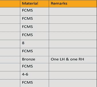
Note:FCMS-freecuting mildsteel CHc –cap head. FHc –flathead cap screw.CRS –Cold Rolled Steel.
Thefollowing notescover some of the moreunusual machining operations:
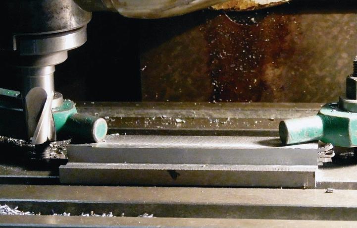
Rear guide 2and front guide 3: I’ve used twopartsfor guiding the sliders 14,toavoid the use of aspecial Tslot milling cuter.This meansitispossible to adjustbyshim packing between 2 and 3 to geta small amountofplay, to allowslightlateral rocking of the knurl holders 16.Toachieve good geometry,it’snecessary to clamp the blank directly on the machine table, photo 3 Assemble the twoparts on the sliders, or with a120mm (minimum)length of 15mm squareCRS, align lengthwise and drill and setthe pins 21.The block 2 and 3 is then drilled, tappedand reamed. Setnow the screws 22 to lock the guide parts 2 and 3
Slider 14: Forgood geometry,the side groovesmustbemade with a side cuter at the same seting of the machine vice foreach operation, see photo 4
Driving screw 6: To ensurecoaxiality,the threads areroughcut between chuckand centre, and finished with adie.
Driving knob 11: Be careful as the tapped part must be lefhand thread to fit 6 (2/3 of the length)and


this case if youreverse the jawitwill be necessary to reversethe locking mechanism foritnot to protrude outside the jaw.
Place the nuts 7 in the sliders 14 and fit them on the screw 6 in symmetrical positions relativetothe centrepart of the screw.Set the whole inside the guiding blocks 2 and 3.Don’t forget to put some grease between the threads and on the sliding surfaces.
Fit the washer 8 with its screw 9 on 6.Fit the collar 10 on 11,don’t forget to place asmall brass pad under the screw 13;screw the whole on 6 (it could be worth lockingaxially the sliders 14 with aclamp to ease this job). Adjust 11 forslightaxial play, setand tighten 12
Assemble the whole on the holding shank 1,screw on the axle 4,adjust forslightaxial playand tightenthe counternut 5.All the moving contact points should receivesome grease.
Assembling the knurls 17 and knurl holders 16 is straightforward.
It’so nly necess ary to changet he knur ls and the knurl ho lders, se e photo 6 and fig. 2 .This to ol wo rks liket he moreu sual type, photo 7 ,t he up pe rk nurl is cut ting while the lowe r is crush ing fo ra fo rwardrot at ion of the la the spindle (t herei sak ine ma tics ex plana tion in Mo del En gi neer 454 3), but the re sul ti svery go od af te ro ne pass only and the depth of cut adjus tmen ti se asyw ith the gradua te dc ollar.
Alwaysb ec aref ul to sett he righ t knurl at the righ tp lac e, and the knu rl holders 24 in the righ tp os i t i on !They mu st be as shown on fig.2o ryou ’ll obta in bad lo ok ing kn ur ls crossi ng at 30 degrees ins te ad of 90 de gre e s. Fo r example, if yo uwan ttogof ro mt he sma ll dia mete rp osi ti on (lef toff ig.2 ) to the large diamete rp os i t i on (c en tre of fig.2 )t he lowe rk nur lh old e rw il lb e exchanged with th eh ighe ro ne bu t the knurls al so nee dtob eexc ha nged between the holde rs .Remember th at the screws 25 mus ta lwaysl oo k towa rd the la the chuck.
Th erei s0.4mm plays pecifie d


Additional Parts ListFor Cut Knurling:


between parts 24 and 14,s op art 24 can rota te around part 15 to give about 1.5 degree cle aran ce .B ec areful to check the inclina tion re la tive to the fe eding direction, photo 8 .I f therei sn oc learance, so me swarf is cr ushed on th em ac hine dk nu rl sa nd theywon’t fo rm cl ea nly
Th eh olding shank 1 is clampe di na to olholder; adjus tt he pivot axis (p ar t 4 )toc en treh eigh t.
Ad jus tt he cross slide fo rt he knurl’sa xis to be in avert i cal plane al ong th el at he’s axis -as trip of 1mm thick ga ugep la te can help,s ee


photo 9
Ti gh te nt he knurls un til jus t con tacting the job fo ra bout 1.5mm length, ‘zero’ the gradua te dc ollar
Giveas quirt of cutting oil befo re st arting the spindle.
Ti gh te nt he knurls (q uiteq uickly to avoid do uble knurls)o nt he running part, taket he knurl pitch from the gradua te dc ollar,feed fo ra fewm illimetres and stop the spindle to review the depth obtained.
St art the la the, go to the st arting position to correct the depth if ne cessary,e ngaget he self-a ct to

machine the knurled par t.
Sometimes the righ t- hand helix is deeper than the left-hand one; it’s necessary to increase the depth of cut from 1.2 to 1.4 knurl pi tc hes to curet his problem.
Stop the la the af te rc ompletion and re move the at tachmen t, photo 10 shows the re sult with mild steel.
In the next ins talm en tI will given otes on making these p arts and illus tratef urther additions fo ri nternal knurling aw ide ra nge of diamete rs
To Be Con tinued.


at 44 degrees which is connected to the weighshafreturn spring,which we will come to later. If youlike, youcould finish the job of properly by drilling a 5/16” hole, 15/16” deep from the centre flangeoutwards. No,Iknownoone will ever see it but youwill knowthatit is there!
We will nowcome on to the weighshafreturn spring, fig 59.First of all, thereisabit of fabrication to do but Iamsurethatitwon’t hurt! This wasone thing Imissed of my own 4MT as it would nothavebeen visible because of the tanksso-really sorry chaps,Ihaven’t taken anyphotos.
Thereisa longshafontowhich the spring is fited and thatis33/8” long. Thereisa plate whichhas apiece of 3/32” welding rodacross the centrebut perhapsI should have said half abar as it needs half filingaway! This is just to givea litlebit of pivot to the spring when the gear reverses. Thespring needs abit of trial and error,but Iwould guess it should be no morethan20swg wirex3/8” diameter.
Ithink the next thing has to be the reverser gear box. Imade twelve paterns forthis piece of equipment and it is nowonsale at TheSteam Workshop.Itwas very gratifying that


we did sell afew hundred of these when Iwas in business,but Imade all of these parts while one of my friends wasmaking apatern forthe manifold forthe BR Standardengines. There areactually thirteen castingsinthe kit of parts as thereare twouniversal joints. Ihavemade severalgear boxes forvarious people and Istarted on the main castingwhich has the indicator drum on theside. Photograph 130 shows Geofmachiningthis piece. (I had to usethe photosthatGeofWhittaker took formewhile he wasbuilding 75069.) He only had to takeabit of a skim out of it. Thenextjob wastodrill

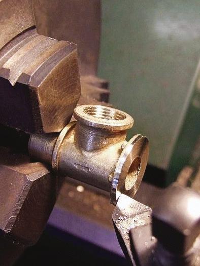
andtap the branch and this is shown in photo 131.Itwill also be advantageous to machine down the flangeofthe branch as thin as possible to give beter clearance to the operating handle, bearing in mind thatyou also need to machine the branchsothatthe lockis uprightonce assembled.
As shown in photo 132,I provided
achuckingspigot so that the flange could be machined. Ihavejustshown, in photo 133,wherethe hole needs drilling to giveaccess to the grub screw on the shaf.One thing Imustsay about the indicatordrum is thatyou need to counterborethe back of it so that it will fit over the protruding boss wherethe shafisfixed in.The cap is just fixed on


with atinydropofsof solder.Ihave chosen the gearssothatthe indicator drum reads the cut-ofs correctly.Once the gear boxisall machined and assembled it is nowtime to fix the stand in place; photo 134 shows this bolted into the cab and photo 135 shows thegear boxinits rightful position. Photograph 136 also shows the reverser gear boxin


Athirdviewtoshowhow it fits snugly.

138: Additional universal joints bring operation closer to the driver.
this backwards and forwards to your heart’scontent!
Ih avea lso sho wn in pho to 13 9 the newf ul ls iz erever ser ge ar boxf or 76 077 being fini sh ed of fo nA ndrew Meredith’s wo rk bench.
One morel ittle job tha tyou can do in this sess ion is ma ke the va cuum re servoir.T his is quit ea visible


it em on yo ur engine so even if it is ad umm yi tn eeds to be theref or comp le te ness. Ih avep rovi ded th e dr aw ing fo ri ti n fig 60 .I ti sj us ta tin can, re ally,a nd it is bolt ed to the engine with ac ouple of st ra ps to hold it in place. It needs bolting cen tr ally to the back of the cross st ay be tween the mo tion
br acket s. Ia mh oping tha tI ha ve jus t given it ab it of clear ance to ke ep it from re st ing on th es ta yb elo w. Pho to gr aph 140 sho ws it sitting theren icely out of the wa y. Please no te ,h owever,Im ay ha ve sho wn it on the dr aw ing the wrong wa yround. Th ei nle ts hould be on th el ef th and side of the engine.