




❖❖ Crossness Adding glamourto thepumping ofsewage Cornwall LNWRsingle wheeleris readytoroll RadioControl Wheresteam andelectronics meet Rust Whereitcomes from–howto stopit RubySwann takestotheroad BUILDATWINCOMPOUNDWINDINGENGINE THEORIGINALMAGAZINEFORMODELENGINEERS Vol.232No.47405–18April2024 Joinouronlinecommunity www.model-engineer.co.uk















© 2023
EDITORIAL
Editor: Martin R Evans
MEeditor@mortons co uk
Deputy editor: Diane Carney
Designer: Druck Media Pvt Ltd
Club News: Geoff Theasby
Illustrator: Grahame Chambers
Publisher: Steve O’Hara
CUSTOMER SERVICES
General Queries and Back Issues
01507 529529
Monday-Friday: 8 30am-5pm
Answerphone 24hr
help@classicmagazines co uk
www classicmagazines co uk
ADVERTISING
GROUP HEAD OF INVESTMENT – Lifestyle & Tractor Publications | www talk-media uk
Mason Ponti
mason@talk-media co uk
Investment Manager: Chris Jeffery
By post: Model Engineer advertising, Mortons Media Group Media Centre Morton Way
Horncastle, Lincs LN9 6JR
PUBLISHING
Sales and distribution manager: Carl Smith
Marketing manager: Charlotte Park
Commercial director: Nigel Hole
Publishing director: Dan Savage
SUBSCRIPTION
Full subscription rates (but see page 486 for offer): (12 months, 26 issues, inc post and packing) –UK £128 70 Export rates are also available, UK subscriptions are zero-rated for the purposes of Value Added Tax
Enquiries: subscriptions@mortons co uk
PRINT AND DISTRIBUTIONS
Printed by: William Gibbons & Son, 26 Planetary Road, Willenhall, West Midlands, WV13 3XB
Distribution by: Seymour Distribution Limited, 2 East Poultry Avenue, London EC1A 9PT
EDITORIAL CONTRIBUTION
Accepted photographs and articles will be paid for upon publication Items we cannot use will be returned if accompanied by a stamped addressed envelope and recorded delivery must clearly state so and enclose sufficient postage In common with practice on other periodicals, all material is sent or returned at the contributor’s own risk and neither Model Engineer, the editor, the staff nor Mortons Media Ltd can be held responsible for loss or damage, howsoever caused The opinions expressed in Model Engineer are not necessarily those of the editor or staff This periodical must not, without the written consent of the publishers first being given, be lent, sold, hired out or otherwise disposed of in a mutilated condition or in other unauthorised cover by way of trade or annexed to or as part of any publication or advertising, literary or pictorial manner whatsoever


http://www facebook com/modelengineersworkshop

http://twitter com/ modelengineers



Vol. 232 No. 4740 5 – 18 April 2024
488 SMOKE RINGS
News, views and comment on the world of model engineering
489 BUTTERSIDE DOWN
Steve Goodbody returns with further tales of the trials and tribulations of a model engineer’s life
492 IMLEC 2024
Rod Ainsworth invites you to compete in this year’s efficiency competition at Southport
494 BUILDING 3020 CORNWALL IN 5 INCH GAUGE
Jim Clark builds a model of Francis Trevithick’s LNWR 2-2-2 locomotive
500 G1 OR 16MM LOCOMOTIVE RADIO CONTROL
Malcolm Batt uses BBC micro:bit computers to add radio control to a 32mm locomotive
504 GRINDING THE TARCUTTA CAMSHAFT
Gerard Dean needs a pair of camshafts for a V12 motorcycle engine so decides to grind them himself
506 THIXOTROPIC METALS – ‘ALLOY 14’
Geoff Theasby strays into the cutting edge of metallurgical science
507 SMEE NEWS
Martin Kyte reports from the Society of Model and Experimental Engineers
508 RUST FORMATION AND PREVENTION IN THE WORKSHOP
Neil Raine looks at the causes of rust and how it may be prevented




512 POSTBAG
Readers’ letters
513 MERRYWEATHER SELF PROPELLED STEAM FIRE ENGINE
Werner Schleidt finds an old boiler and is inspired to construct a fire engine around it
517 LNER B1 LOCOMOTIVE
Doug Hewson presents a true to scale fiveinch gauge model of Thompson’s B1
523 A TWIN TANDEM COMPOUND STEAM ENGINE
Graeme Quayle presents an interesting design for a compound winding engine
525 BOOK REVIEW
Henk-Jan de Ruiter reads about the restoration of antique toys
526 THE AMERICAN LOCOMOTIVE
David Rollinson takes a look at the classic and ubiquitous 4-4-0 locomotive
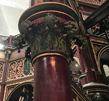
529 A VISIT TO THE CROSSNESS ENGINES
Robert Hobbs visits a rather grand and ornate pumping station in South East London
532
CLUB NEWS
Geoff Theasby compiles the latest from model engineering clubs around the world
535
CLUB DIARY
Future Events
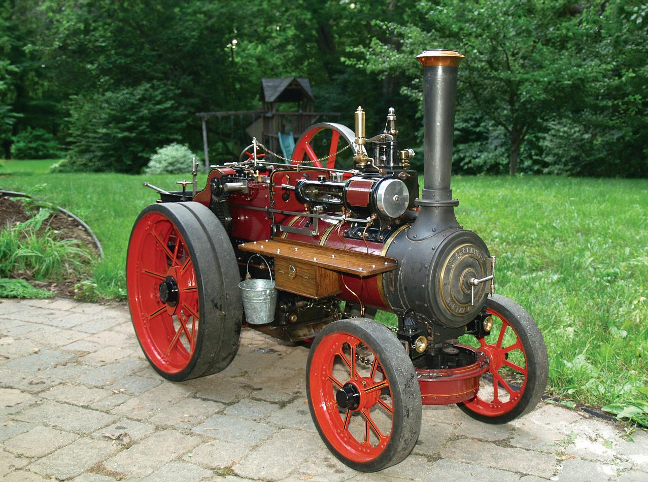
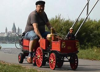
Steve Goodbody’s 3 inch scale Allchin ‘Royal Chester’ traction engine Ruby Swann (photo Steve Goodbody)

www.model-engineer.co.uk 483
Mortons Media Group Ltd, Media Centre, Morton Way, Horncastle, Lincs LN9 6JR
Published by
Fax:
Tel: 01507 529589
01507 371066
Mortons
Media ISSN 0026-7325
www model-engineer co uk
O N T H E C O V E R . . .
This issue was published on April 5, 2024. The next will be on sale on April 19 2024 Crossness Adding glamour o the pumping o sewage Cornwall LNWR single le wheeler is ready ll Radio Control Where and electronics et Rust Where it from – ho stop Ruby Swann takes to the road BU LD A TWIN COMPOUND W ND NG ENG NE COM O N THE ORIG NAL MAGAZINE FOR MODEL ENG NEERS AL AGAZ NE FO – pSUBSCRIBE & SAVE UP TO 49% See page 486 for details www.model-engineer.co.uk 513 523

















Enjoy 12 months for just £68











Great reasons to subscribe
>> Free UK deliver y to your door or instant download to your digital device
>> S ave money on shop prices
>> Never miss an issue
>> Receive your issue before it goes on sale in the shop
SUBSCRIBE AND SAVE
P R I N T + D I G I TA L D I G I TA L O N LY P R I N T O N LY Q uar terly direc t debit for £19 1 year direc t debit for £68 1 year credit/debit c ard for £74 Q uar terly direc t debit for £22* 1 year direc t debit for £85* 1 year credit/debit c ard for £88* 1 year direc t debit for £50* 1 year credit/debit c ard for £54* *Any digital subscription package includes access to the online archive
classicmagazines.co.uk/ M E D P S 01507 529529 and quote MEDPS Lines are open from 8.30am-5pm weekdays GMT O ffe r e nds D e ce mb e r 31, 2024 Subscriptions will s t ar t w ith the ne x t availab le issue D ire c t D e bit p ay me nt s w ill continue on the agre e d p lan unless you te ll us othe r w ise To v iew the privac y p o lic y for MMG Ltd (pub lishe r of M o de l Engine e r), p lease v isit w w w. mor tons .co.uk /privac y Pl e ase v i s i t w w w.c l ass ic m ag a z i ne s .co.u k / te rm s for fu l l te rm s & con d i t ions . ( 8
AParklands Railway Week
2½ Inch Gauge Rally





 MARTIN EVANS Editor
s I write this, the weather has turned positively spring-like and model engineers are beginning to come out of hibernation, blinking in the unaccustomed sunlight. Where I live, it is clear there has been a change in the weather as there has been no rain now for over 24 hours, for the first time, it seems, in several months Temperatures have also managed to haul themselves into double figures so everything is looking very promising There are plenty of events to go to over the next few weeks, to make the most of the improving weather, and here I have listed a few of them.
Bassett-Lowke Rally
DIANE CARNEY Assistant Editor
Mar tin Evans can be contacted on the mobile number or email below and would be delighted to receive your contributions, in the form of items of correspondence, comment or ar ticles. 07710-192953
MEeditor@mortons.co.uk
The second Bassett-Lowke Rally will be held at the Northampton Society of Model Engineers track on Saturday May 18th Visiting locomotives are welcome in 7¼, 5 and 3½ inch gauges to run on their raised and ground level tracks There will also be Gauge 1 and Gauge 2 running in the marquee and the 45mm and 32mm garden railway will also be available.
To register please contact Kevin West on westkev58@ gmail com

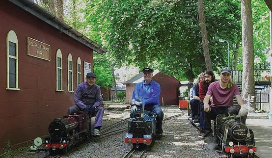
The annual Parklands Railway Week at Hemsby, Norfolk is a very popular event amongst the 7¼ inch gauge fraternity but, sadly, this year’s is to be the last. It is to be held during the week from May 25th to May 31st If you wish to bring an engine you need to notify leighsteamer@ btinternet com and further details can be found at www sevenandaquarter org


3½ Inch Gauge Rally
If you are into 3½ inch gauge and are based not too far from the Midlands then you may be interested in the 3½ inch gauge rally at Rugeley Power Station The rally is organised by the Rugeley Society of Model Engineers and takes place on the weekend of May 18th/19th If you are interested you will need to book in advance (secretary@ rugeley-sme org uk) and bring the usual paperwork (boiler test certificate and insurance documents) Food and refreshments will be available both days. For accommodation, both Travelodge and Premier Inn are situated nearby

No need to feel left out! There is a 2½ inch gauge rally at the Cheltenham Society of Model Engineers on Sunday May 12th, from 10am to 4pm
Engineering in Miniature
I was very sorry to hear the news that our rival publication, Engineering in Miniature, is to close after the May issue Perhaps you think this odd, coming from the editor of this magazine However, many of our readers may remember that I was for a while editor of Engineering in Miniature (EiM) so I am (if you like – or even if you don’t like) ‘family’ I followed Chris Rayward as editor (a hard act to follow) and was given a one-day crash course in putting together a magazine by him and proprietor Chris Deith Chris then shepherded me carefully through the process over the subsequent year or so until he passed the magazine over to Warners Chris was an excellent manager and I am very grateful to him for the guidance he gave me I am glad though that he did not see the demise of his magazine, which he started back in 1979
The two magazines provided two distinct styles in their presentation – a good thing for the readership I hope that former readers of EiM may find the style of this magazine tolerable I read in Facebook recently that our style is considered by some a little ‘pompous’ – so I shall endeavour to be a little more ‘umble in future, Master Copperfield!
Another commentator on Facebook made the very apposite remark that life will become progressively more difficult for printed magazines, as the future is digital That is quite right and so, as well as being a little more ‘umble, we shall have to try to adapt to the changing modus operandi of the publishing industry Our survival surely depends upon it
Model Engineer 5 April 2024
488
Kevin West
Register Parklands
Details Parklands
Details 3½ Inch Gauge
The View from Butterside Down m
Pa r t 8 : T h i r d H a n d a Tr a n s p o r t a t i o n , Pa r t 4


Steve Goodbody takes a random walk through model engineering
Continued from p 451 M E 4739 March 22
With all other possibilities exhausted, with a dead fire and a cobbled together manometer as evidence, the author concluded that Ruby Swann’s Royal Chester based design as producing very little of that most desirable commodity for a lively firebo draught
nd that raised t o good uestions hy and hat could be done about it
Disclaimers and denials
ver the years, ith the rise of the nternet and an evolving plethora of model engineering forums and ebsites on both sides of the tlantic, have noticed there is one topic hich, despite all reason and rationality, seems to provo e much angst, ire and gnashing of teeth amongst a portion of the message typing populace and that sub ect is draughting, so, ith a sense of trepidation, here is fair arning that am about to touch on this dangerous sub ect and strongly advise sensitive readers to
cover their eyes and s ip for ard to the ne t article if they ant to avoid the potential fallout
o ever, in the fervent but probably naive hope that this ill help s eeten the pill, let me admit right up front that am most definitely not an e pert on draughting no very little of the or s of reenly, ll, ylala, Chapelon, iesl, orta, e aitre and others and have underta en no original research can honestly say that have contributed absolutely nothing to the global body of no ledge on the sub ect and don t intend to start no hould you feel strongly about anything that follo s, therefore, am sure you are in the right and you ill receive no argument or complaint from me
n short, everything hich follo s is simply a report of my first hand e periences ith a three inch scale single cylindered llchin traction engine named Ruby Swann, a doubled up version of ill ughes s Royal Chester design and hile strongly suspect that some of these findings
may be broadly applicable to other engines, especially as the supply of decent coal becomes more and more scarce and may therefore be of interest to other engine o ners especially traction engine o ners ho are rarely considered hen draughting is discussed, have noticed am not claiming this for a fact o there!
onestly, you can t be too careful these days, can you
Running the numbers
o , ith that behind us and for any brave souls ho may still be follo ing along, let me cautiously add that hile not an e pert on the sub ect, as an avid reader of this magazine for rather a long time have noticed that the draughting arrangements of many of the popular locomotive designs published in these pages over the years seem to follo a broadly similar set of guidelines, possibly originating from enry reenly in the s but really don t no and hich, if the reports are to be believed, seemingly result in steaming success Table 1 is included here as a reference for
Approximate Guideline
last nozzle area of the grate s surface area
enturi cho e area of the grate s surface area
enturi cho e height above the blast nozzle
inimum chimney height and ma imum chimney diameter above the blast nozzle
ased on a in cone of steam emerging from the blast nozzle
ased on a in cone of steam emerging from the blast nozzle
489 www.model-engineer.co.uk >>
Table 1: The approximate draughting guidelines, discerned from miniature railway locomotive designs
what will follow; it summarises those approximate ratios, at least as discern them, but have no idea if these ratios and arrangements are any here near the best that can be achieved and ma e no claim, recommendation or comment regarding their accuracy, relevance, efficacy, degree of perfection, or ability to histle the arseilles in the ey of ma or ut thin you no this by no
tepping bac and applying a bit of logic a dangerous thing, no , ho ever, certainly li ed the fact that these ratios too the grate s size as their starting point because, to me, that made intuitive sense s reasoned it, rightly or rongly, a ell designed boiler ould sensibly be based upon the needs of the cylinders and, if so, then the size of the boiler s fire and therefore the size of the boiler s grate, must have been determined by the heat needed to produce sufficient steam from that boiler to feed those cylinders nd ith the grate s size so determined, then the ashpan and ues should also have been designed, respectively, to allo sufficient air into the fire and to enable the resultant gases to efficiently escape, all to eep the ames merrily burning o bring this train of thought to its conclusion, if the boiler as thus ell designed and the grate, ues and ashpan ere properly proportioned in turn, then the sole purpose of the draughting as to produce
sufficient vacuum inside the smo ebo to dra enough air through the fire bed to ma e it all or ince the appropriate amount of air is determined by the size of the fire and since the size of the fire is substantially determined by the size of the grate, then the grate s size seemed to be the appropriate starting point for the draughting design s say, this train of thought made sense to me earteningly, ob anderson s article, Front End Design, appearing in the une , 4 edition of Model Engineer, also used the grate s size as the basis for its front end calculations and seemed to support my supposition o ever, hile the blast nozzle size calculated using r anderson s formula agreed closely ith the roughly ratio to grate area hich seemed typical, his appro imately 2 ratio for the venturi cho e as far smaller than the hich appeared more typical and decided to stic ith the latter o complete the picture, hile ne that cylinder bac pressure as also an important factor, decided not to orry about that too much unless the guidelines suggested needed a considerably smaller blast nozzle than Ruby Swann’s current fitting to get the fire burning
Compare and contrast
t this point, convinced that inade uate draughting as
Guideline Size Ruby Swann’s Actual Size
last nozzle diameter inches inches
Cho e diameter for a inch diameter blast nozzle inches ver 2 inches
enturi cho e height above a inch diameter blast nozzle inches o venturi
inimum chimney height above a inch diameter blast nozzle inches inches
a imum chimney e it diameter for a inch diameter blast nozzle and a inch high chimney 2 4 inches 2 inches
the root of my troubles, no had the ability to generate a set of theoretical dimensions as a guideline against hich to compare Ruby Swann’s actual details o ever, to add one further un no n into the mi hich is more of a caveat than a disclaimer, given that the guideline dimensions
ere presumably based upon the needs of a t o cylinder rail ay locomotive had no idea hether they ere e ually applicable to a single cylindered traction engine
ith no other information or guidance available, ho ever, had to start some here and these ratios seemed to be as good a place as any here
o, ho did Ruby Swann’s details compare ith these figures ell, after assembling the relevant formulae into a spreadsheet to perform the necessary calculations
ithout repetitive effort, it certainly appeared that her front end dimensions deviated significantly from the guideline ratios, especially hen it came to her chimney n fact, the chimney, ith its lac of a venturi to help dra air from
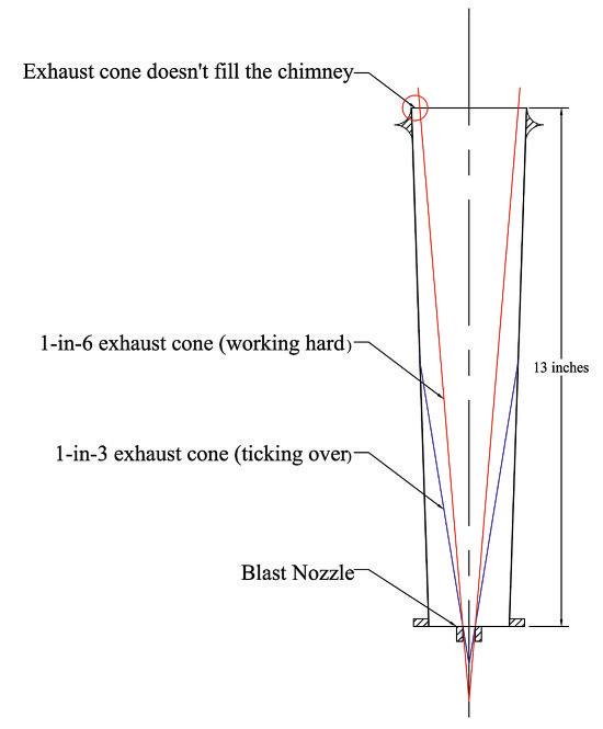
the smo ebo and its large and increasingly larger diameter as it tapered upwards to the top, seemed to miss the mar by a significant margin in all respects and Table 2 shows ho the numbers stac ed up ssuming the guidelines represented reasonable if appro imate targets, then hat did these figures suggest et s ta e each in turn, starting ith the seemingly over large diameter at the top of Ruby Swann’s chimney and see s imagine it, as a steam engine or s harder, the et of steam e iting the blast nozzle speeds up and causes the cone of e panding steam hich is shooting up ards to correspondingly narro the faster the et, the narro er the cone and vice-versa nd this, it seems to me, is the li ely reason behind the in and in cone ratios in the guidelines the former representing the et hen the engine is or ing lightly and the latter hen the engine is or ing hard nd from hat can recall from many hours spent unravelling the mysteries of uid dynamics at
490 Model Engineer 5 April 2024
Table 2: A comparison of Allchin Ruby Swann’s actual details against the Table 1 guidelines
The 1-in-3 and 1-in-6 cones emerging from Ruby Swann’s blastpipe, drawn to scale
Fig 3
university and beyond, thin that my imagination is on the right trac , but m sure that someone ill let me no if m rong
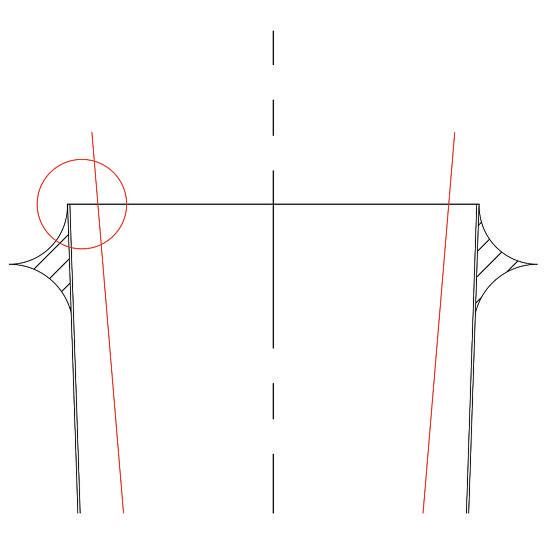
o ever, it also seemed to me important that hen an engine is or ing its hardest, the chimney s diameter must be sufficiently small for the in cone to fully fill it before e iting out the top because, if it does not, air may creep do n the annular gap bet een the steam et and the chimney and deplete the smo ebo vacuum nd in Ruby Swann’s case, the calculated numbers in able 2, hich are also sho n pictorially and to scale in figs 3 and 4, suggested that, ith its inner diameter of 2 inches, the top of Ruby Swann’s chimney as roughly of an inch too large, implying that the cone of e hausted steam may not be filling the chimney hen the engine as or ing hard n short, the guidelines suggested that improvement might be had if the chimney s overall diameter ere reduced by at least inch, but preferably more e t on the list, hen or ing lightly, although the in cone of steam ould certainly fill the chimney,
the chimney s large overall diameter, fully 2 inches at its smallest point, meant that it ould do so at a much greater elevation than if the chimney contained the venturi cho e suggested by
the guidelines nd, hile believe that a venturi is not a common front end design feature for a traction engine, it certainly seemed plausible that adding one ould help mi the smo ebo gases ith the exhaust steam, draw those gases from the smo ebo and reduce the smo ebo pressure and create more draught in the process n short, the guidelines suggested that adding a venturi ith a inch diameter cho e at a height inches above the blast nozzle, thereby reducing the chimney s diameter by roughly inch at that point, ould represent another possible area for improvement inally, hat about that blast nozzle diameter ith a guideline of inches versus the actual diameter of inches, it certainly appeared that Ruby Swann’s blast nozzle as slightly undersized o ever, if increased, ould that resolve the problem hile the spreadsheet suggested no her chimney ould still be too big even ith a larger blast nozzle this as an easy e periment to perform and so,
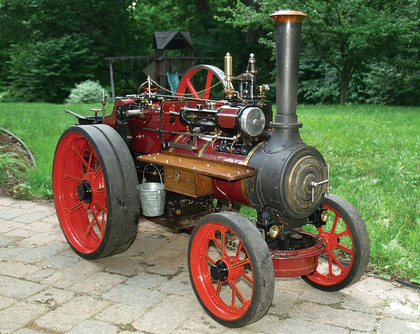
after half an hour of lathe or , repeated the manometer tests ith a selection of larger nozzles and confirmed that, as far as could detect, they made not a hit of difference to the smo ebo vacuum hich, in all cases, remained undetectable n conclusion, ere to believe the guidelines, then they ere telling me that a narro er chimney, together ith a proper venturi to help dra the gases out of the smo ebo , ould be avenues orth e ploring ut ho to achieve these t o goals ithout ruining Ruby Swann’s other ise attractive and true to scale appearance photo 16 ell, that s a very good uestion but see that our editor is pointedly tapping his atch and so the ans er ill have to ait until ne t time m afraid
To be continued
491 B U T T E R S I D E D O W N www.model-engineer.co.uk
The top of the chimney depicted in fig 3. The chimney’s diameter is too large to be filled by the 1-in-6 cone of steam, possibly allowing air to enter her smokebox through the annular gap.
A narrower chimney would certainly spoil the elegant appearance of an Allchin traction engine, in the author’s view!
Fig 4
16
I M L E C 2 0 2 4

Rod Ainsworth, chairman of Southport Model Engineering Club, invites entries for this year’s IMLEC

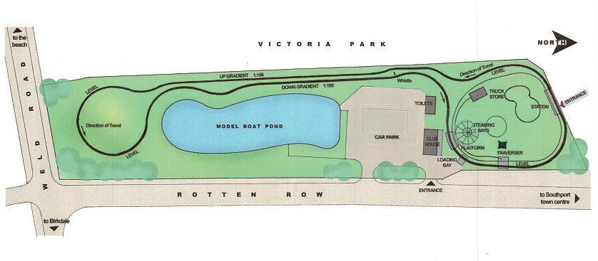
The 54th International Model Locomotive fficiency Competition is to be held at Victoria Park, outhport on th 2 st uly 2024
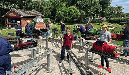
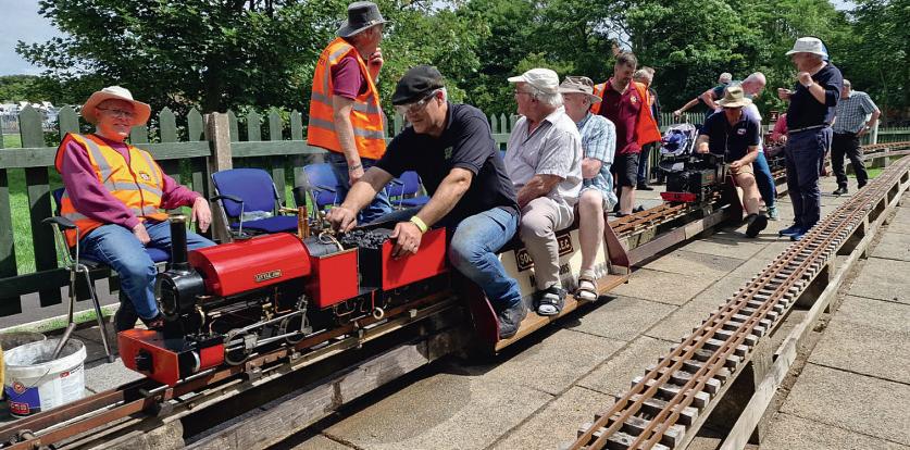
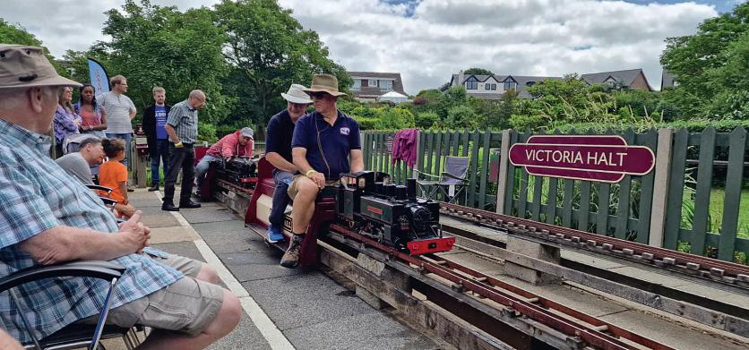
The members of Southport odel ngineering Club, assisted by members of the eyland Club, are proud to be the hosts of the 54th anniversary event of C Our club was formed in 1978 and has currently over 2 members who range from raw novices to professional engineers The club has extensive and attractive grounds and a clubhouse situated at the southern end of Victoria Park, Southport with access off Rotten Row We have two raised tracks each catering for 3½ and 5 inch gauge locomotives he first of these tracks also has a 2½ inch gauge track and is 640 feet long and the second track is 1733 feet long. We also have a gauge 1 and 32mm track of and feet respectively The grounds have been judged to be utstanding by the oyal orticultural ociety s t s our Neighbourhood’ scheme Southport is a delightful Victorian seaside resort, no n as he Classic esort Southport is renowned for its gardens, sandy beaches and
many golf courses, including oyal ir dale here the pen olf Championship has been held on numerous occasions Its elegant town centre provides a vast array of shops and a wide selection of restaurants Lord Street is the main street ith many pavement caf s situated under a glass and cast iron ictorian canopy Visitors to the event will be required to purchase a ticket hich ill provide entry to the club grounds and the event itself The cost will be £5 per day or 2 for the three days of the event There is ample on and off-street parking available for both entrants and visitors There will be spaces available close to our grounds from hursday till onday th 22nd uly for tents, camper vans and caravans These
will be under our control for which there will be a nominal charge r en avier is in charge of our caravanning and camping arrangements and visitors wishing to make use of these facilities on the weekend should contact him
here is also a Caravan Club site, for members of the caravan club, within a few minutes’ walk, but pitches here have to be booked well in advance as it very popular location! Visitors will be responsible for making their own arrangements with the Caravan Club outhport is a popular seaside resort and has ample hotel, guest house and bed and breakfast accommodation and again visitors will be responsible for making their own arrangements in this respect
492 Model Engineer 5 April 2024
Southport Model EngineeringIMLEC
ithin easy travelling distance of outhport is the fine market town of Ormskirk and if the event at the club and the attractions in Southport are not enough to retain your interest then a visit on aturday to the open market is well worthwhile
There will be a dedicated area for trade stands and if any traders are interested in having a spot over the weekend please contact en as soon as possible
The Southport Club has a ebsite southportmodelengineering. club This website will be kept up-to-date with information about the competition and the main point of contact ill be en avier by e mail ublicity southportmodelengineering club or mobile 2 259845)
The members of Southport odel ngineering Club would like to extend a warm
welcome to new and past entrants of C as ell as all spectators We look forward to meeting you over the ee end and to having a really great, mutually en oyable ee end Our main aim is to provide all entrants and spectators ith a thoroughly en oyable competition Refreshments, including alcohol, will be available throughout the weekend with an evening of live music on the aturday night There will also be an opportunity for visitors to run their locomotives on our trac s on riday and aturday evenings, subject to the usual paper or but e cluding any entrant who has not completed their run!
or any competition to run successfully and be fair to all entrants there have to be rules This event is no exception and the following paragraphs outline the basic rules which apply over the ee end he
choice of two sizes, grains and beans
If more applications are received than can be run as planned then a list of reserve engines will be considered from the applications in order of receipt. The applicants will be informed if they are to be placed on the reserved list and they can decide hether to partake or not If not the next one on the list will be offered a similar option The number of reserve entrants will be limited to six and there will be a tick box on the application form where applicants can indicate their interest in a reserve place very effort ill be made to find a slot for the reservists to run over the weekend, but we cannot give any guarantees
competition will take place over three days ith the first run starting around mid day on riday, depending on the number of entrants
The competition will be run on our 5 and 3½ inch gauge dual gauge raised track and will be open to applicants on a first come first served basis by application form only he forms should be completed in full in order to be considered and accepted A strict time line will be observed on all entries. The competition will be restricted to a total of 28 measured runs using the usual practice of the driver sitting on a dynamometer car, loaned to us by eyland Club, coupled to the engine No initial circuits will be allowed prior to the run and a full fire at the start of the run will be observed A set of the rules will be sent to the successful entrants
The coal supplied for the event will be anthracite in a
Prizes will be awarded to the competitors finishing in first, second and third places in the competition for the Martin vans Challenge rophy plus a prize for the best performing 3½ inch gauge locomotive f you ish to enter the competition you should apply for an entry form via the ebsite or from en avier ll application forms will be sent out by email to the prospective entrants at the same time, as soon as possible, and the closing date for the return will be th ay
The request for an application form will not guarantee entrance into the competition A form will be sent to all potential applicants at the same time, and acceptance into the competition ill only be considered after a completed form is submitted A brief description of the entrant’s locomotive and a short history of the driver will be required and a photograph would be appreciated ny previous C inners should declare the year and details of their inning entry ll successful applicants ill be notified by post and they ill be sent copies of maps, rules and local information Reservists and unsuccessful applicants will also be notified
493 I M L E C www.model-engineer.co.uk
ME
PA RT 3

Jim Clark builds the famous LNWR 2-2-2 – the frst locomotive earmarked for preservation
Continued from p 459
M E 4739 March 22
Eccentrics
The eccentric straps for the valves ere another significant design challenge These have to be mounted on the centre axle and, as the boiler sits right above this axle, there is very little room Figure 8 shows the eccentrics and a cross-section
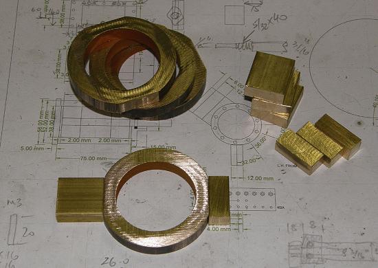
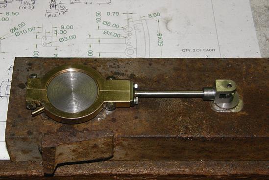
through the main axle, which demonstrates the problem and details my solution I resolved this problem by splitting the eccentric straps horizontally instead of vertically, as is usual practice (photos 17 and 18) The centre eccentric is the smallest, with
only a 5mm offset giving a 10mm stroke and this is used for a water pump When the various eccentric straps are fitted to the eccentrics, they ust clear the bottom of the boiler at their highest point of rotation
The eccentric strap bodies were fabricated from slices
494 Model Engineer 5 April 2024
B U I L D I N G 3 0 2 0 CORNWALL in 5 Inch Gauge G
116 Ø38 Ø50 Cy nder Cyl nder 6 5 5 o f s e Ø159 8 3 3 1 6 3 11 11 5 o f s e 2 6 Ø42 Valve Eccentrics Mat l Cast i on (4 requ red) 10 Ø110 Bo ler 100 5 5 Eccentr c pos t ons ind ca ive only Shown at maximum ve t ca throw to demonstra e clearance from bo er Outer F ame Outer Frame Ø16 Valve Eccentr c Straps Ma l B onze (4 requ red) 6 3 Ø 3 8 Ø 4 0 38 Eccentric Rod Plates (4 requ red) 8 1 3 2 0 Axle Pump Eccentric Strap Ma l B onze (1 requ red) Axle Pump Eccentric Mat : Cast ron can be sp i as shown o so d) 8 Ø 3 2 Ø 3 4 38 Spl t ine Split ne Pump Rod Plate (1 required) 10 1 3 2 0 1 Sp i ne O l sp got O spigo Ø32 6 4 E x p a n s o n n k C L 32 5 nner Frame Inne Frame 3 8 6 2 3 9 Offset 4 15 Valve Eccentric Rod Clev s Mat Stee (4 equ red) 12 3 4 3 Ø 5 Th ead 3/16 x 40 Valve Rod Clevis Pin Mat : 4140 steel 4 requi ed) 13 1 2 16 1 4 Ø10 Ø5 117 6 Valve Eccentric Rod Assembly (2 eft/r ght pa rs requ red) Braze rod in o p ate then set up assembly on g and braze rod end nto c ev s to ensure exact eccentr c rod eng h Rev Ecc Rev Ecc Fwd Ecc Pump Ecc Fwd Ecc
This shows most of the component parts for the eccentric straps
ere is one complete eccentric strap, valve rod and clevis, finish machined and sitting on the jig that was used to ensure the correct valve rod length
Eccentric design details.
17 18
Fig 8
of the same phosphor bronze hollow bar that I had used for the cylinders, with ‘ears’ of brass silver soldered to either side. These were split through the middle ith a fine slitting sa and machined up to fit the eccentrics
Photograph 19, taken much later in the build, shows the finished eccentric straps in place and connected up to
the valve gear The boiler will sit between the wheels immediately above them The space limitations are obvious. The small brass spigots sticking out the right-hand side of each eccentric strap are for e ible silicone lubricator pipes that will bring oil down to the eccentrics from reservoirs on the running boards The eccentrics are otherwise quite
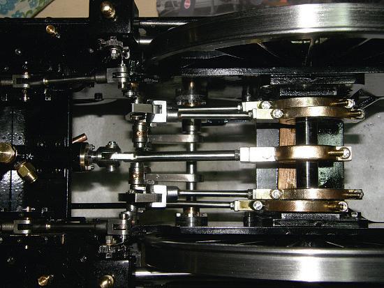
inaccessible once the boiler is in place
The chassis
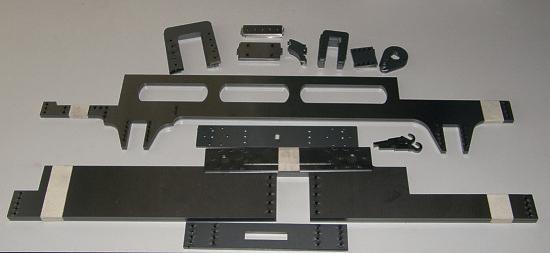
In the meantime, I had detailed out the frames and plates (fig ) that make up the chassis to a point where these could go
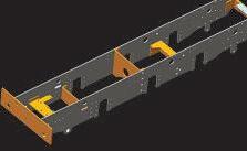
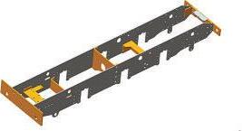
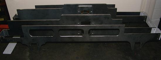
out for laser cutting (photo 20) bit of filing, some riveting and a little more silver brazing and the kit of parts turned into the basic framework (photo 21). The two inner frames and the front and rear buffer beams are riveted and brazed together
495 C O R N W A L L www.model-engineer.co.uk >>
210 Front Buffer Beam Inner Mat : 3mm MS plate 630 630 0 Outer Frames Mat : 3mm m ld steel plate (2 required) Inner Frames Mat : 5mm m ld steel plate (2 requ red) 3 1 40 22 9 6 1 9 2 205 205 130 E x p a n s o n l n k r 1 2 7 Va ve CL Cy inder CL B a c k h e a d W e g h s h a t E x pa n s o n i n k C L 1 8 6 1 2 2 5 5 3 2 95 118 107 0 148 3 9 7 2 4 2 1 0 7 30 6 7 7 4 32 8 4 5 8 7 3 3 205 0 205 0 Front Front 9 3 29 244 3 3 3 9 148 194 88 5 8 1 2 56 6 3 7 6 7 9 4 3 1 3 8 Frame End Channels Fabr cate from 20 x 20 stee angle welded edge to edge & then machined to size (2 front & 2 rear required) 20 192 34 Rear Buffing Plates Mat l: 3mm m d steel (2 requ red) Rear Buffer Beam Mat l: 5mm m d steel p ate 3 3 3 3 6 7 3 3 6 7 9 26 50 1 0 Boiler firebox 1 0 0 Plan View Showing G A Of Frames And Location Of Main Components R vet then braze nner frame & frame channe to front buffer beam nner 6 3 1 Notch out front outs de frame channel to clear cy inder R vet through buff ng plate then braze outer frame & frame channel to buffer beam Drill & tap frame channe 6BA Secure outer frame w th 6BA screws Dr l & tap frame channel 6BA secure outer frame with 6BA screws 3 4 8 1 8 20 25 Csk from beh nd and braze in long 8BA screws to secure buffers 2 1 0 3PCD 63 9 5 8 Front Buffer Beam Centre Mat : 12mm close grain hardwood Varn sh or clearcoat Front Buffer Beam Outer Mat l 1 6mm MS 53 1 4 212 3 6 112 Front Buffer Beam Hook Plate Mat l 6mm MS 2 0 56 5 Front Draw Hook Mat : 5mm MS p ate F le to shape 5 8 20 18 1 4 Horizonta rame s retcher V e c a a m e t e c h e Locat on of axle pump Screw stretchers to inner frames then braze Location of ax e pump Locat on of vertica & hor zontal frame stretchers between nner frames Ø6 D&T 8BA D&T 6BA 20PCD 4 9 86 127 6 4 Outer Plate For Cyl Bracket Mat : 3mm MS p ate (2 requ red) 1 7 16 65 8 5 65 Inner Plate For Cyl Bracket Mat l 3mm MS plate (2 requ red) 3 1 1 1 Locate these holes from tapped holes in inner frame during assembly 42 5 35 1 9 D & T 4BA 12 15 14 98 Sides For Cyl Bracket Mat : 3mm MS p ate (4 requ red) 26 3 9 3 1 1 1 1 7 7 r26 Cylinder Bracket 2 required Top view 4BA screws to back of cyl fixing b ock 4BA screws to inner frame Braze plates together to form cyl bracket 1 7 6 8 12PCD Notch out to c ear exhaust port as req d 20 1 2 7 28 0 135 5 0 1 3 2 5 8 6 6 5 20 20 20 1 2 5 Vertical Frame Stretcher Mat’ : Fabr cate from 6mm steel p ate Screwed and brazed together 1 0 0 50 Horizontal Frame Stretcher Mat : 6mm steel plate 60 1 0 0
kit of mild steel plates ready to be put together.
Looking straight down on to the main axle between the driving wheels
A
Frames partly assembled
9 19 20 21
Design details for the chassis components Fig
o ever, some udicious fiddling and application of shims in appropriate places eventually sorted the problems out, and the front view of the Axle and suspension details.
to form a rigid central core for the chassis In addition, there is a vertical and a horizontal frame stretcher that is screwed then brazed across the inside of the inner frames ust behind the cylinders, to add even more rigidity The horizontal stretcher also provides a convenient place to mount the axle water pump. This core part of the chassis is never disassembled again; however, the outer frames and other components are screwed on to it and they are all removable
The wheel sets had already been completed, so no ust needed to machine up the axle boxes, fabricate two large springs and hangers for the main axle boxes and sort out a fe other minor fi tures and fittings fig )
This was quite an exciting part of the build, because it seemed to go from a lengthy period of head-scratching, problem solving and fiddling with drawings on the computer to something that began to look like a real locomotive surprisingly quickly (photo 22) did have some difficulties fitting up the cylinder assemblies which had also been made earlier As these are turned inwards so the valve chests sit at an angle facing in towards the smokebox, it as a little difficult getting the cylinder mounting blocks silver soldered at exactly the correct angle during initial fabrication
The error I made during fabrication came back to bite me during assembly of the chassis, as the two sides ended
up being slightly asymmetrical and things like the valve centres and the connecting rods did not quite line up as they were supposed to

496 Model Engineer 5 April 2024
Ø120 2 8 22 18 2 14 inside 22 8 5 9 3 18 8 4 5 1 2 18 2 4 10 10 2 6 3 Ø18 Ø14 2 2 Ø18 Ø12 116 186 Outer Frame Outer Frame 38 30 1 0 Coil spring suspension pocket mil ed in horn/frame 18 7 4 2 5 4 Rivet horn to outer frame with 3/32 steel rivets then braze 34 8 70 36 8 3 Rivet horn to nner frame with 1/8 steel rivets then braze 6 3 8 1 2 Eccentric positions are Indicative only 116 Ø 1 2 Ø 1 6 116 42 200 Leading/Trailing Axles Mat l: 4140 steel round bar Ø16mm Driving Axle Mat l: 4140 steel round bar Ø16mm Spring Suspension Plate Mat l: 3mm steel (2 required) Leading/trailing Axle Horns Mat l: 5mm MS plate (4 required) Leading/trailing Axle Keeps Mat l: 3mm stee (4 required) Axle Bush Mat l Bronze Axle Bush Mat l: Bronze Axle Box Cover Mat l: Fabricated brass Leading/trailing Axle Box Assy Mat : Cast iron body & bronze bush Spring Buckle (2 required) Driving Wheel Axle Boxes Part Cross Section Through lead ng/trailing axles Part Cross Section Through driving axle Driving Axle Keep And Frame Stiffener Mat l: 5mm steel Driving Axle Horns Mat l: 5mm steel plate (2 required) Spring Hanger (4 required) GA Of Driving Axle Suspension Detail Of Top Spring Leaf Outer Frame Outer Frame 1 6 5 0 1 4 Ø16 1 5 36 40 5 Ø20 15 3 Oil pocket Braze small plate on back of horn to provide extra material for suspension pocket 116 19 154 Ø 1 4 5 Ø 1 6 Inner Frame Inner Frame 2 4 Ø25 1 1 5 Ø20 Ø25 Ø16 34 D&T 4BA 8 25 25 8 5 5 1 5 Ø36 Outs de face of inner frame 6 Braze suspension rod nto buckle & suspension p ate 3 5 9 10 13 8 D&T 6BA for locating pin Spring leaves: 0 8mm spr ng steel 10mm wide cut ength to suit Substitute tufnol for some leaves to adjust spr ng rate if req d Ø6 5 Ø3.2 1 3 8 88 Braze hanger rod into clevis thread & screw into spring pin Locating hole D&T 4BA into frame/horn 2 7 5 Ø4 10 Ø65 110 7 0 4 0 15 6 3 4 7 100 Driving ax e CL 6 9
10
A rolling chassis! Fig
22
Crossheads and connecting rods.
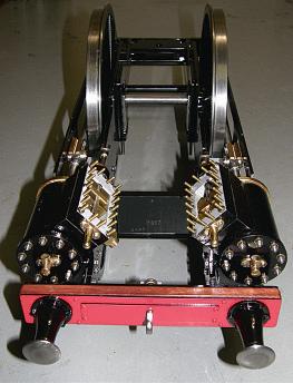
ront view with cylinders fitted.
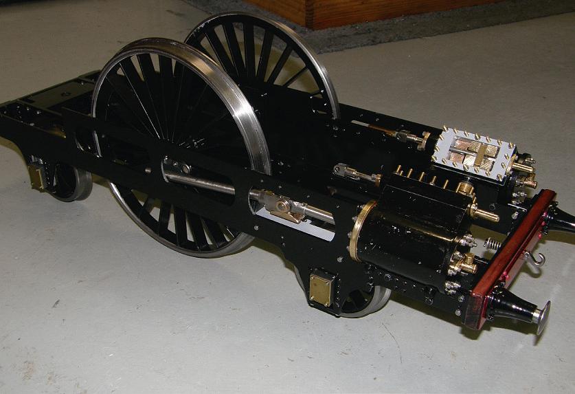
locomotive now looked as shown in photo 23
finished the crossheads and connecting rods (fig ), which I made as close as I could to the details I could see in the photos, as these are very prominent and visible features of Cornwall (photo 24)
497 C O R N W A L L www.model-engineer.co.uk >> 280 175 Part outer frame LH side shown Side View Of Cylinder Crosshead & Connecting Rod Assy 114 5 Cyl nder ong tudinal CL Driving axle CL 50 stroke 80 O lw ay Locate from holes in guides dur ng assy D&T 6BA 3 8 6 Locate holes for valve guides during assy D&T 8BA Upper Crosshead Guide Support Channels (2 required LH & RH) 175 Thread & p n clevis to connecting rod Braze big end on to connecting rod Dr ll o lw ay through to pivot Dri l tap & fit oi cup for b g end Connecting Rod Assembly (2 requ red LH & RH) 13 10 Ø 1 2 5 Ø14 Ø11 Big End Bush Mat l: Phosphor bronze (2 requ red) 4 3 25 Ø14 Ø8 Ø 1 1 Clevis Bush Mat’ : Phosphor bronze (4 required) 30 1 3 11 14 1 6 Ø 1 4 Ø10 1 9 19 Ø14 Press bushes nto clevis 20 5 1 2 5 Connecting Rod Clevis Mat’ : Steel (2 required) Ø10 22 Crosshead Body Pin Mat l: Steel (2 required) 12 5 1 2 5 Ø95Ø125 30 8 22 Ø10 Crosshead Body Mat : Steel (2 required) Bore recess Ø10 2mm deep r33 30 1 2 3 2 2 6 5 Crosshead Slipper Mat l: Phosphor bronze (4 required) Ø5 Ø6 6 25 3 25 2 Inner Bush Mat l: Phosphor bronze (2 required) Ø5 6 Valve Rod Bush Mat l Phosphor bronze (2 required) Ø6 Ø5 9 2 6 Outer Bush Mat : Phosphor bronze (2 required) Fix w th 8BA screws Secure w ith collar & pin Section Through Valve Crosshead Assy 40 25 32 6 Check height of slot from job 5 Outer Valve Crosshead Guide Mat’l Steel (2 required) Check he ght of s ot from job 40 25 2 0 1 0 8 9 3 3 Locate holes for valve crosshead guides from holes in nner frame dur ng assy Inner Valve Crosshead Guide Mat l: Steel (2 required LH & RH) D mp e for retaining grubscrew Ø8 20 5 Crosshead Pivot Pin Mat l: 4140 steel (2 required) 3 0 12 12 5 30 Dr ll & tap for retain ng grubscrew Thread & pin to piston rod (LH/RH) Ø8 Crosshead Body Sub-assy Fabricate braze & bore cross-hole for pivot 24 5 Ø Pivot Pin Mat l 4140 stee (2 required) Press inner and outer bushes into va ve crosshead clevis 1 0 6 13 Valve Crosshead Clevis Mat l: Steel (2 required) 80 2 0 3 30 5 5 3 2 6 Location of o lw ay (top guides only) Crosshead Guides Mat’l Steel (4 required) 9 6 Press bush nto b g end Ø125 Ø12 Ø10 1 6 28 12 1 2 36 3 Connecting Rod Big End Mat’l Steel (2 required ) 38 Lower Crosshead Guide Support Channels Mat l Fabr cated 20 x 20 steel angle welded edge to edge & machined to size (2 requ red LH & RH) 2 0 Locate from holes in frames dur ng assy D&T 6BA 90 Locate from holes in guides during assy D&T 6BA Cut out to c ear leading wheel 35 Locate from frames D&T 5BA Press valve rod bush into valve rod end Ø5 5 11 6 Valve Rod End Mat l Steel (2 required) Braze end to valve rod Valve Connecting Rod Clevis Mat l Steel (2 required) 7 5 3 5 34 Braze end to connecting rod Press bush into c evis Outer Frame Inner Frame 38 Cy nder vertical CL Dr ving ax e CL Engine vertica CL Valve vert cal CL 86 50 1 3 0 3 2 5 Fix crosshead support with 6BA screws (Check va ve centre d ms from job) Side v ew of valve crosshead & connecting rod assy Part inner frame LH side shown Va ve CL Rocke r arm Valve connection rod Va ve rod 65 5 L nkage to machan cal ubr cator (one each side) To machan cal ubricator Valve rod Valve connect ng rod Rocker arm Top View Of Valve Crosshead And Connecting Rod Assy Cross Section Through Cylinder Crosshead Assy
e now have a rolling chassis with cylinders fitted and pistons that go back and forth as the wheels go round rogress indeed!
23 24
Fig 11
498 Model Engineer 5 April 2024 Press bottom bush nto each l nk Braze top bush nto both inks Fix with M3 high tensile cap screws Secure with col ar & pin Ø 6 16 Lifting Pin Mat l 4140 steel (3 required) Expansion And Lifting Link Assy (2 required LH & RH) Lifting Link Assy (2 required) 20PCDØ14 Ø25 Ø8 6 3 Weighshaft Bush Mat’ : Phosphor bronze (2 required) Ø8Ø6 Ø12 12 6 Lifting Link Top Bush Mat l: Phosphor bronze (2 required) Ø8Ø6 3 Lifting Link Bottom Bush Mat Phosphor bronze (4 required) 1 7 5 1 7 5 Ø8 1 0 0 Press l fting arm bush nto each ink Braze ft ng arms to we ghshaft Front V ew from above P n reach rod arm assy to weighshaft 38 1 90 ° Side view Weighshaft And Lifting Arms Assy Reach rod to reversing lever n cab Ø6 6 1 3 Reach Rod Mat l: 12 x 3mm steel Reach Rod Pin Mat l: 4140 stee 3 8 1 Ø8Ø12 Lifting Link Mat l Steel (4 required) Press l fting arm bush into reach rod arm Braze reach rod arm into reach rod bush Ø10 3 8 1 Ø8 15 10 Ø12 Ø8 Reach Rod Bush Mat’ : Steel Reach Rod Arm Mat : 5mm stee Reach Rod Arm Assy 5 0 5 Ø6 8 1 0 5 1 0 5 6 Ø3 0 8 r123 Expansion Link Mat l 6mm gauge plate (2 required) Ø5 8 1 1 3 Die Block Mat l 6mm gauge plate (2 required) Ø5 1 2 16 5 Ø10 8 5 6 3 6 9 3 19 D&T M3 Braze pin into base 1 2 Ø3 Pivot Pin Mat l: 4140 steel (2 required) Pivot Pin Base Mat l: 3mm steel (2 requ red) Spacer Mat l 3mm steel (2 requ red) Rocker Bushes Mat l: Phosphor bronze (2 required) 3 5 Ø6 Ø4 6 3 Ø12 Ø6 Developed Rocker Profile Mat l: 3mm steel (2 requ red) Ø6 Ø8 Ø8 2 0 9 2 5 38 1 Ø8Ø6 6 0 Ø8 Ø8 Ø13 Ø12 Die Block Bushes Mat l: Phosphor bronze (2 required) press into d e blocks Lifting Arm Bush Mat l Phosphor bronze (3 requ red) Lifting Arm Mat : 5mm steel (2 required) 6 2 Ø5 Ø4 Rocker And Die Block Assy (2 required) check dims on job Die block Rocker p vot (fit through ho e in inner f ame) V a v e C L Braze die block pivot into rocker Die b ock secured with 1mm split p n & th n washer Rocker secured with collar & pin Valve rod Press rocker bushes nto rocker Bend rocker to al gn with va ve CL 4 3 1 Die Block Pivot Mat l: 4140 steel (2 required) Ø40Ø6.0 15 0 8 1 Expansion Link Bushes Mat Phosphor bronze (4 required) Press nto expansion nks Ø5 Ø6 6 2 Rocker Pivot (2 required) 15 Ø 6 Braze rocker pivot into base 4 12PCD Rock e r a r m L f t ng l n k 117 6 Valve CL 86 Weighshaft Rocker pivot 127 2 5 Front Setout Of Valve Gear On Inner Frames Inner frame Ax e CL Reach rod L fting arm Valve connecting rod Valve crosshead 124 1 4 9 Fwd eccentric rod Rev eccentric rod 6 4 4 3 1 117 6 F w d R e v Crank 70 38 1 V a v e C L E x p a n s o n n k C L Rocker pivot Weighshaft 17 5 100 V ew from front Inner Frame 18 6 32 5 GA Of Valve Gear LH eccentrics only shown Axle & eccentric CL 3 8 1 Reach rod to revers ng ever n cab Fwd Ecc Rev Ecc 12 5 26 4 2 0 2 5 3 3 25 3 25 Lap - 3 3mm Port opening - 3 25mm Valve travel - 2 x(lap + opening) =13 1mm Cutoff - 1 -(2 x(lap + opening)/travel)^2 =75% Fully open front + 6 55mm Fully open rear - 6 55mm Cutoff = 75% Inlet port open Exhaust port open Eccentrictriangle24° T D C B D C Zeuner Valve Diagram 3 35 26 4 13 1 Eccentric throw & valve travel Eccentric advance angle 24° 6 55 Crank Valve And Port Dimensions 3 35 19 7 12 5 7 1 1 . 5 6 4 8 5 6 Valve And Drive Dog D&T 3/16 x 40 22 6 7 5 Details of the valve gear. Valve timing
Fig 12
Fig 13
In late 2019 there was a disruption to progress caused by the arrival in my workshop of a certain Flying Scotsman locomotive, which diverted my attentions for some time But that is another story!
The valve gear
hen finally got bac to Cornwall after completing the Flying Scotsman pro ect, there were some fairly tricky details to be sorted out with the valve gear his all needed to fit in between the frames, and as previously mentioned regarding the valve eccentrics, the valve gear must not foul the bottom of the boiler, sitting between and ust above the main a le
I drew up the valve operating mechanism in considerable detail and checked the design parameters against the formula and procedures given in Don Ashton’s book Design Procedures for Walschaert’s and Stephenson’s Valve Gear (fig )
I also ran the design parameters through two versions of valve gear
simulation software, which are available free on-line from Charles Dockstader and Dr Allan Wallace I used the information obtained by fine tuning the simulations to determine the exact lengths of the pivot arms and the correct placement of the pivot points, and to determine the optimum advance angle for the eccentrics
I even went so far as to draw a Zeuner Diagram showing geometrically the timing and cut-off I should expect, as shown in fig 3 The Zeuner diagram shows the relative opening of the ports (the hatched areas) as the crankshaft rotates through a complete cycle from top dead centre (TDC) to bottom dead centre (BDC) and back. This was a method of analysing steam valve gears developed by German engineer Gustav Zeuner in the 19th century, nowhere near as sophisticated as more modern valve gear analysis and certainly not as useful or accurate as the software simulations, but an interesting exercise nonetheless
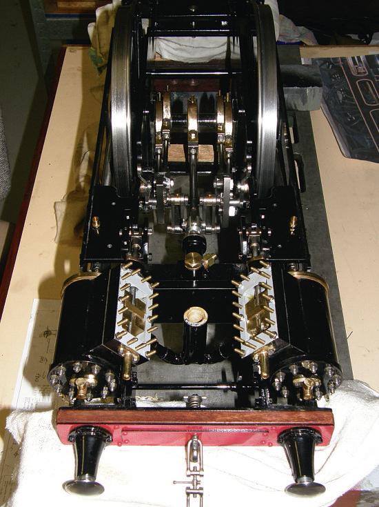
In the centre of photo 25 is the small axle-driven water feed pump, with the left and right-hand side valve gear sandwiched in beside it. The motion for each valve rod is brought up from the die block down below via a cranked pivot arm
Missing in photo 25 is the remaining connecting linkage between the rocker arm and the valve rod crosshead – this is still a work in progress
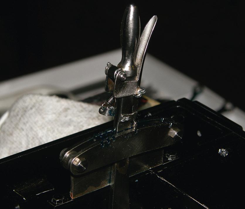
The reversing lever, however ( ), was added at this stage
The valve gear was probably the most difficult although not the most fiddly part of the locomotive. That was because I was trying to get a somewhat overscale design to fit into a very limited space between the frames and under the boiler In the end, I think it has turned out to be quite robust and should provide smooth and reliable running (I hope!)
499 C O R N W A L L www.model-engineer.co.uk
be continued
To
Here is the almost completed valve gear seen from the front of the locomotive
25 26
A close-up of the reversing lever, fitted to the frame at the rear where it will be accessible inside the cab
G 1 o r 1 6 m m Lo co m o t i v e R a d i o Co n t r o l u
s i n g B
m i c r o : b i t Co m p u t e r s o

B C
Introduction
This article describes a method of using a pair of BBC micro:bit computers to provide an economical radio control system for Gauge 1 or 16mm model steam locomotives
The project started during lock down when I decided to build a 32mm locomotive to run on the track at the Wimborne Model Engineering Club I started to develop a loco of my own design but being new to this gauge (my previous build was a 5 inch Sweet Pea) I soon realised the difficulties and comple ities of providing the mechanics at this smaller size, so I purchased a set of kits from Roundhouse
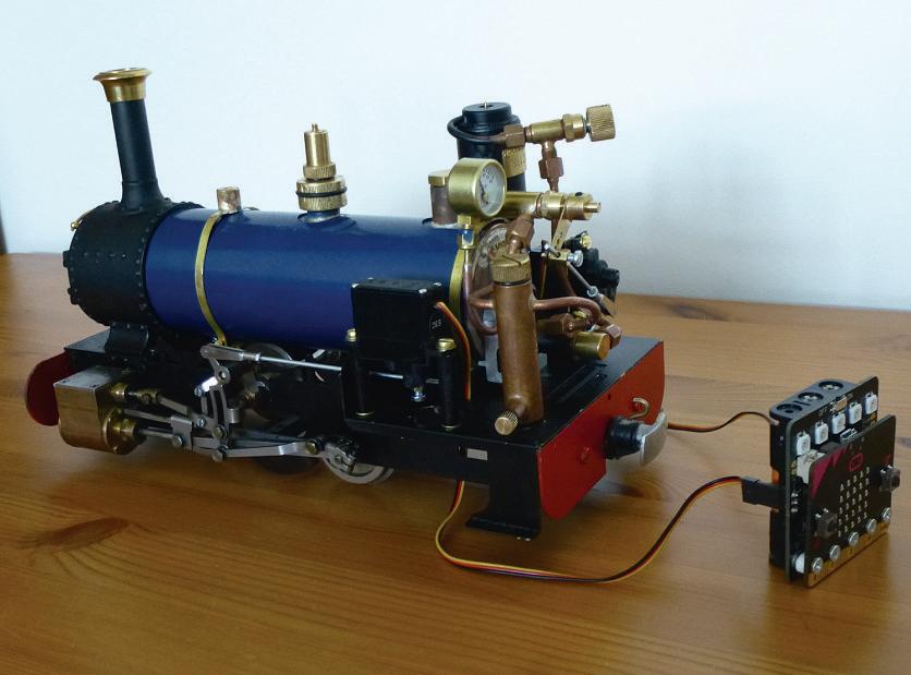
Engineering (photo 1) This picture was taken during the development phase before the cab as fitted lthough a lot of our members like to buy ready to run locomotives for each of the club’s gauges, I like the challenges and satisfaction of running something that I have built So, when it came to providing a radio control system, the same challenge was there s ell as being an active member of our model engineering club, I also help run an engineering club at a local school Our projects, which we roll out to the students, include robotics which are based on the BBC micro:bit computer
500 Model Engineer 5 April 2024
Malcolm Batt shows that building your own radio control system need not be complicated
oundhouse ate before fitting cab showing control servos fitted
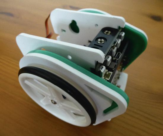
itronik ove robot
1
2


 MARTIN EVANS Editor


