Mark Henderson LACCD Regional Manager, College Technology Services
John Urene BuildLACCD PMO Technology Project Manager
Brent Penner BuildLACCD Regional Safety Manager
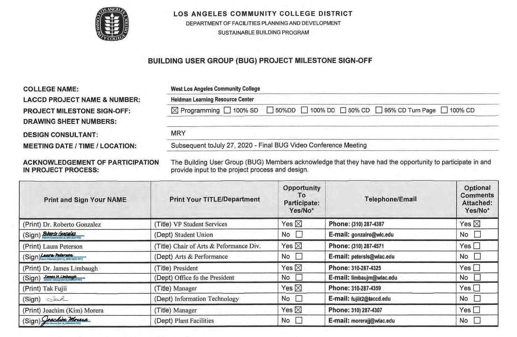
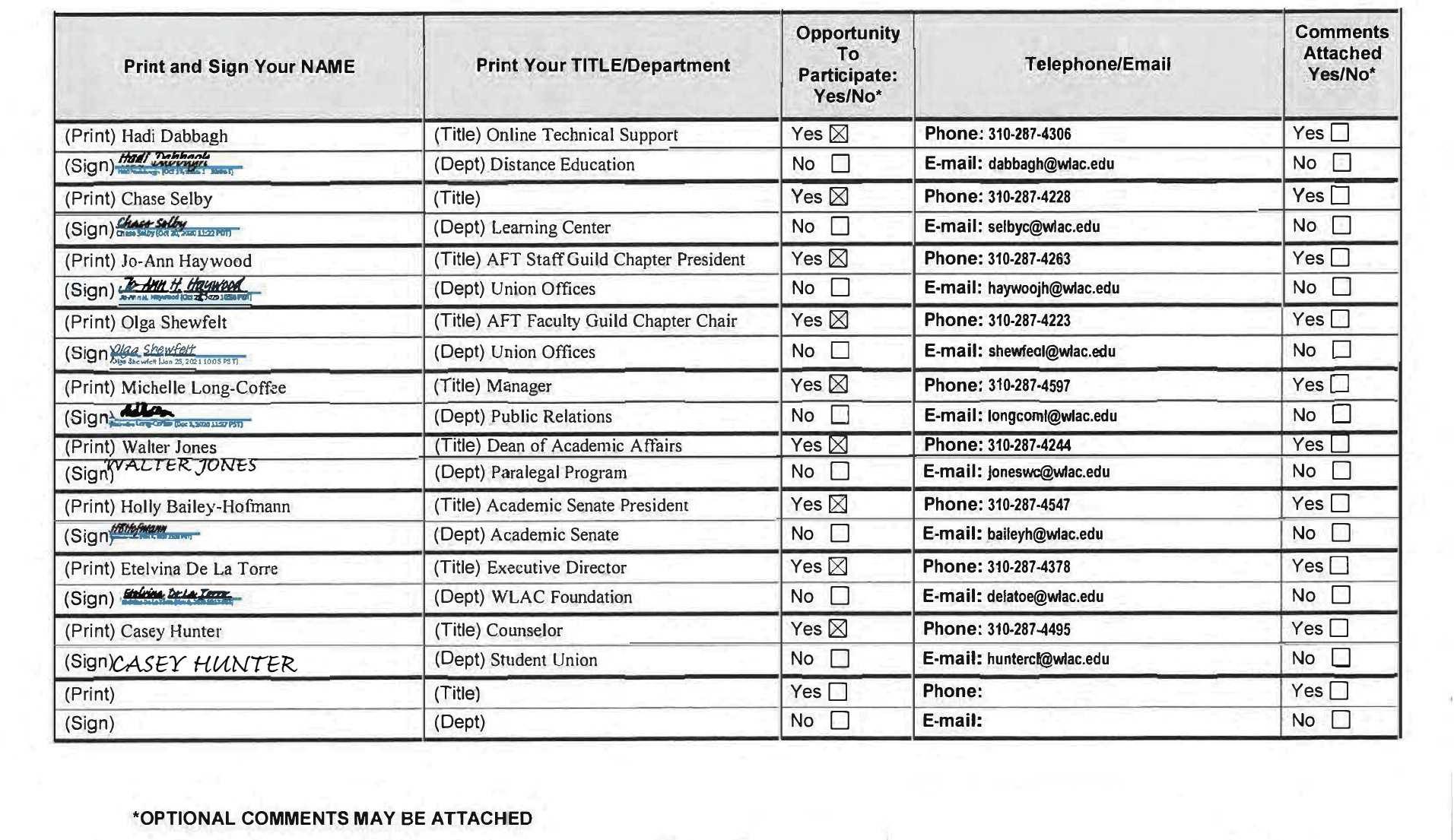
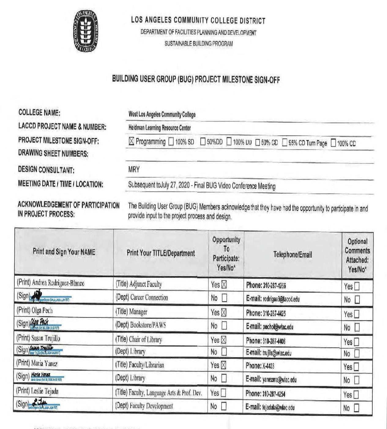
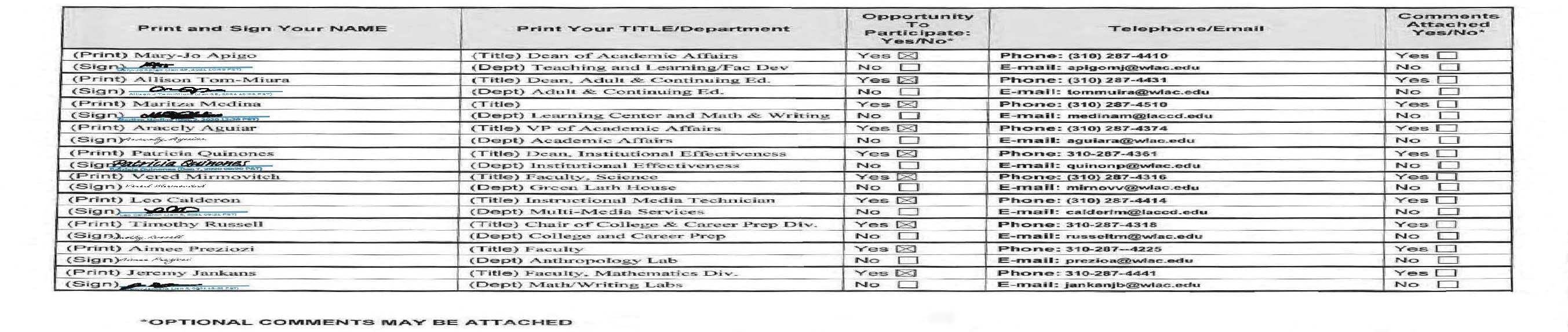
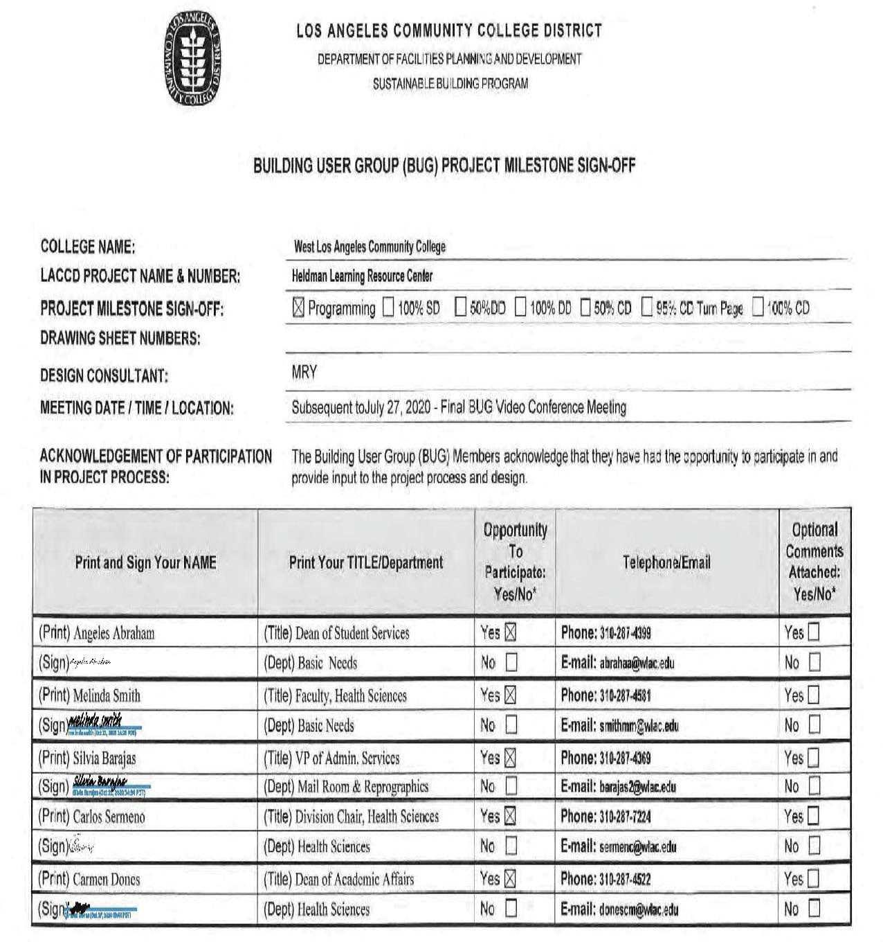
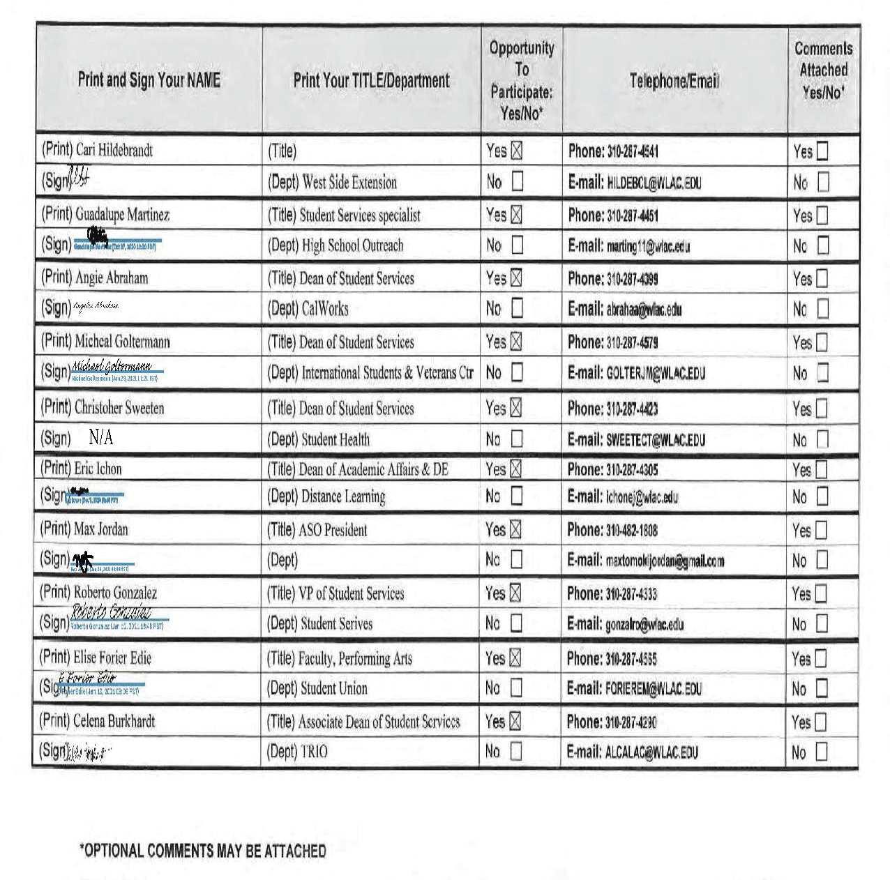
1.2 STAKEHOLDER ACKNOWLEDGMENT OF PARTICIPATION
This Programming and Project Design Criteria (PPC) document represents a collaborative effort between the West Los Angeles College Senior Management (CSM), College Project Team (CPT), Building User Groups (BUG), BuildLACCD and the Design Criteria Team. The following sign-off sheets represent acknowledgement from the aforementioned groups that they have had the opportunity to participate and provide input to the project process and design.
James M. Limbaugh, Ph.D. President
West Los Angeles College
Los Angeles Community College District
Brian Stokes, Ph. D. Vice President for Administration and Innovation
West Los Angeles College Los Angeles Community College District
William Syms, Ph.D.
Vice President Student Services Enrollment, Management & Equity Initiatives
West Los Angeles College
Los Angeles Community College District
Jeffery Archibald, Ph.D. Vice President Academic Affairs & Workforce Development Accreditation Liaison
West Los Angeles College Los Angeles Community College District
Rick Darling Regional Program Director
West Los Angeles College
Los Angeles Community College District
Ricardo Reyes College Project Director
West Los Angeles College Los Angeles Community College District
Neal Matsuno, FAIA, LEED AP BD+C Principal
Moore Ruble Yudell Architects & Planners
Blake Patten, AIA, LEED AP Associate Principal
Moore Ruble Yudell Architects & Planners
1.2 STAKEHOLDER ACKNOWLEDGEMENT OF PARTICIPATION
1.2 STAKEHOLDER ACKNOWLEDGEMENT OF PARTICIPATION
1.2 STAKEHOLDER ACKNOWLEDGEMENT OF PARTICIPATION
2.1 INTRODUCTION
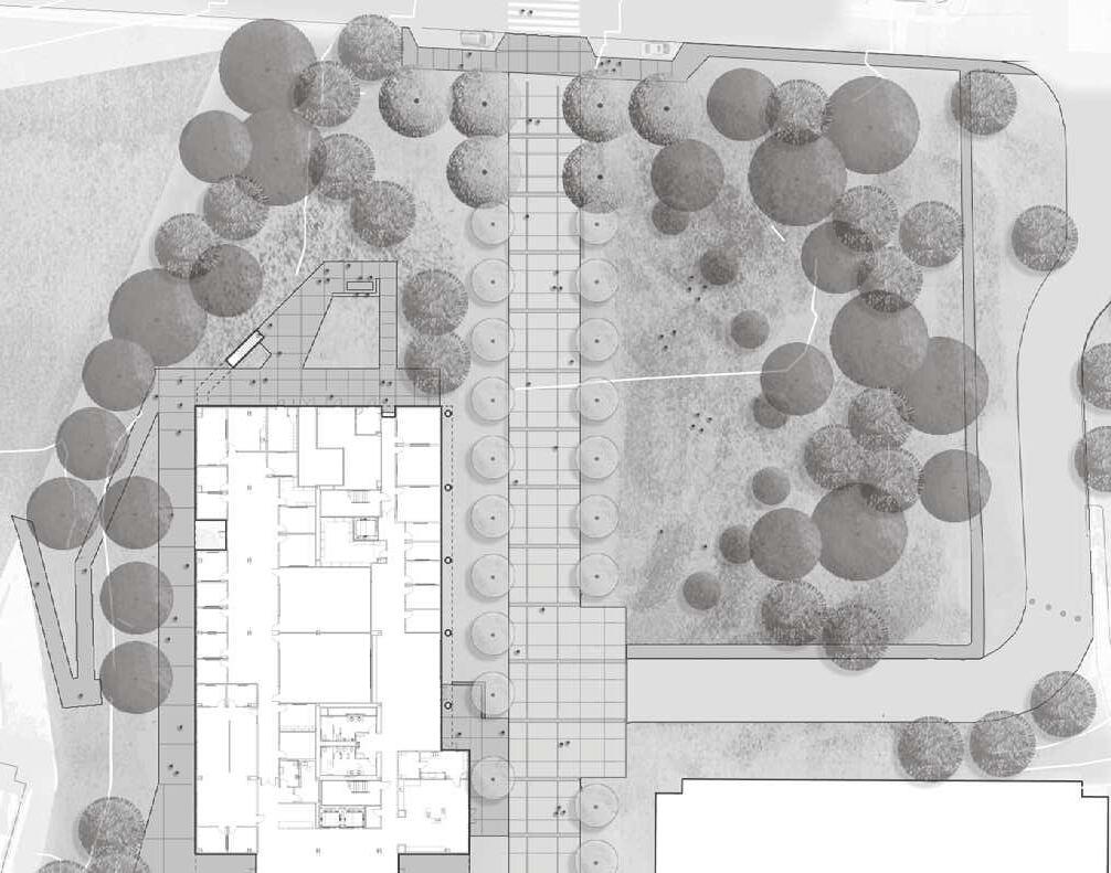
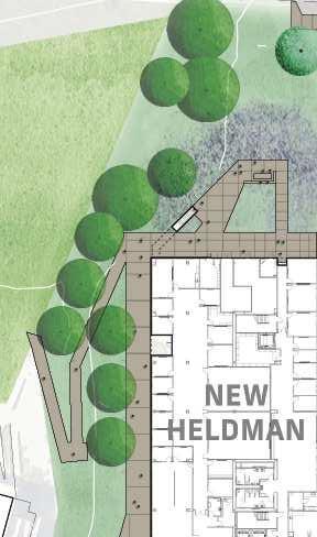
buildings. The old Heldman Learning Resource Center, the largest building on campus, will be removed and replaced by a new Heldman Center, housing similar academic and student-oriented programs in state-of-the-art facilities. Twelve outmoded structures will be demolished and open up campus lands for future development. Major elements of campus open space will be re-worked with new landscaping and lighting, providing dramatic improvements to connectivity, accessibility,
New Imperatives
The project comes at a time when the Los Angeles Community College District is looking closely at how each of its 9 campuses can reduce their inventory of underused, often outmoded buildings and transition to more efficient use of better facilities. In doing so, key educational and social objectives reflect higher education’s contemporary focus on equity, inclusion, and student success in serving its current and future student population.
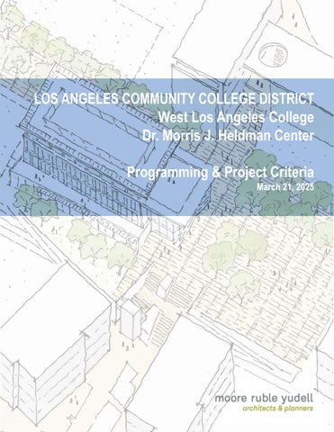
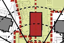
Concept for new Heldman Center and renewal of the West LA Campus
Los Angeles Community College District
The Los Angeles Community College District (LACCD) with nine campuses is a key part of the California Community College System which currently serves approximately 2.1 million students attending 115 colleges across the State. These 115 colleges are all under the jurisdiction of the California Community Colleges Chancellors Office (CCCCO). LACCD colleges serve approximately 217,000 Students (2023-24 annual enrollment) from an area of 882 square miles, across 40 southland cities within the County of Los Angeles. It is the largest district in the California Community College system and the US. The Mission of the Los Angeles Community College District is to foster student success for all individuals seeking advancement, by providing equitable and supportive learning environments at our nine colleges.
Source: LACCD District Strategic Plan, 2018-2023
West Los Angeles College (WLAC)
Founded in 1964, WLAC is the second youngest of the nine colleges in the LACCD, starting to serve students in February 1969 using temporary facilities. In 1973, the construction of the permanent campus buildings began and finished in 1989. Today, WLAC has approximately 10,000 students attending day, evening, and weekend classes. As of Fall 2018, WLAC comprised roughly 8% of students attending within LACCD.
WLAC’s Mission
West Los Angeles College (WLAC) provides a transformative educational experience. WLAC fosters a diverse learning community dedicated to student success. Through quality instruction and supportive services, the College develops leaders who encourage excellence in others. A WLAC education enriches students with the knowledge and skills needed to earn certificates and degrees, to transfer, to build careers, and to pursue life-long learning.
Student Demographics and Characteristics
In fall 2018, approximately 62% of WLAC’s student population was female. WLAC has the second largest proportion of female to male students within the District. Approximately 24% of students at WLAC were 19 years old or younger and 31% of students were between the ages of 20 to 24 years old. Historical data suggests that the College is trending toward a younger student population,
particularly within the 19 year or younger age group. Approximately 45% of WLAC’s students are Hispanic and 23% are African American. WLAC serves the second highest proportion of African American students of all colleges within the District. Although WLAC serves the second lowest proportion of Hispanic students of all Colleges within the District, recent data suggests the proportion of Hispanic students at WLAC is growing.
Instructional Programs
WLAC offers approximately 1,000 courses across 12 different academic disciplines. WLAC also offers one of the most extensive and well-reviewed online distance education programs in Southern California. The academic disciplines offered at WLAC are Art and Performance, Applied Technology, Behavioral Science, Business, Computer Science and Application, Health Sciences, Kinesiology (Physical Education), Language Arts, Liberal Arts and Sciences, Mathematics, Science, and Social Sciences.
WLAC is one of 15 community colleges in California to offer a 4-year baccalaureate program. The College offers 2 bachelor’s degrees, 55 associate degrees, 20 associate degrees for transfer, 34 certifications of achievement, 25 skills certifications, 11 certifications of completion, and 3 certifications of competency.
In fall 2018, approximately 46% of students at WLAC took a course load between 0.1 and 5.9 units. During the same term, approximately 20% of students were considered half time (load of 6.0 to 8.9 units), and 16% of WLAC students took a course load of 12 units or more. In fall 2018, the largest gap between success and retention rates for on-campus credit courses was within basic skills offerings (35.2% gap). The gap between success retention rates for on-campus credit courses within basic skills offerings was also the highest of all Colleges within the District.
Student Service Program
WLAC offers a large selection of Student Service programs with the purpose of guiding and assisting students in their academic/career goals, offering financial assistance, healthcare, housing, employment, and ensuring students receive a complete college experience.
Major Student Services at WLAC include:
• Admissions and Records
• Associated Student Organization (ASO)
• Athletics
• Bookstore
• Business Office
• California College Promise
• Cal WORKS/Gain
• Campus Community Programs
• Career Center
• Child Care
• College 2 Career
• Counseling
• Disabled Student Programs and Services (DSPS)
• Dream Resource Center
• EOP and S
• Financial Aid
• Foster Care – Guardian Scholars
• Graduation Office
• Health Center
• High School Outreach and Recruiting
• International student Services
• Internships
• LEARN
• Learning Center
• Matriculation
• Orientation
• Public Transportation
• Puente
• Student Success Workshops
• Study Abroad
• Transfer Center
• Veterans Office
• Welcome Center.
PROGRAM AND PROJECT CRITERIA (PPC)
In 2019 Build LACCD and STIR Architects completed a Space Utilization Analysis and Preprogramming Report (STIR Report) for the current project, based on LACCD 2017-18 Space Inventory Report and a 2017 ALMA Strategies Space Utilization Study. The STIR Report defines a multibuilding program that addresses the current and future space needs of 29 departments, as well as demolition and/or alterations to existing facilities, new construction, and extensive related site development. The project components described in the report provide the basis for a more detailed program, in effect setting limits on the overall scope of the project.
Moore Ruble Yudell Architects and Planners were selected to refine the project’s goals, priorities, and develop this Project Program and Criteria Document to guide design and delivery of the scope defined in the FPP / White Paper. The PPC is intended to outline project goals, convey program intent, and provide a description of the minimum project scope and requirements. The planning concepts, diagrams and Room Data Sheets contained in the PPC describe functional relationships including approximate sizes and shall not be considered resolved design solutions to be implemented literally. The Design Build Entity (DBE) is solely responsible for compliance with all requirements of the program, college and district standards and all governing codes and laws.
BRIDGING DOCUMENTS
Following the guidance of this PPC, Bridging Documents have been prepared which offer a comprehensive design approach for DBE reference only. The Bridging Documents are included as one to the listed documents in Chapter 7: Appendix.
2.2 PROJECT PURPOSE AND GOALS
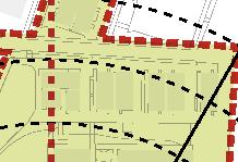
The New Heldman Center project presents five key transformational measures for the WLAC campus that implement the vision established by the prior 2010 Campus Master Plan and subsequent updates in 2013 and 2016. The combination of renovations, new construction and public realm upgrades will provide new resources for the college’s mission of student success while optimizing campus planning for future growth.
Reduce Underutilized Building Areas
An LACCD initiative encompassing the nine district campuses, assessed all campus facilities and identified a number of underutilized and underperforming buildings on the WLAC campus. The District mandated the campus reduce its underutilized building space to align with the needs of the student body and faculty for academic and administrative space per the District’s standards. Additionally, compliance with the District area guidelines makes WLAC eligible for future funding of capital projects.
Demolish Aging and Underperforming Buildings
The collection of aging facilities located in the north-east corner of the campus including the original campus facilities known as the “bungalows” and the HLRC have outlived their service lives, do not meet current accessibility and life-safety requirements and are expensive to maintain. The demolition of these structures will enable the campus to comply with the mandated building area reduction and provides development sites for future academic buildings.
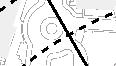
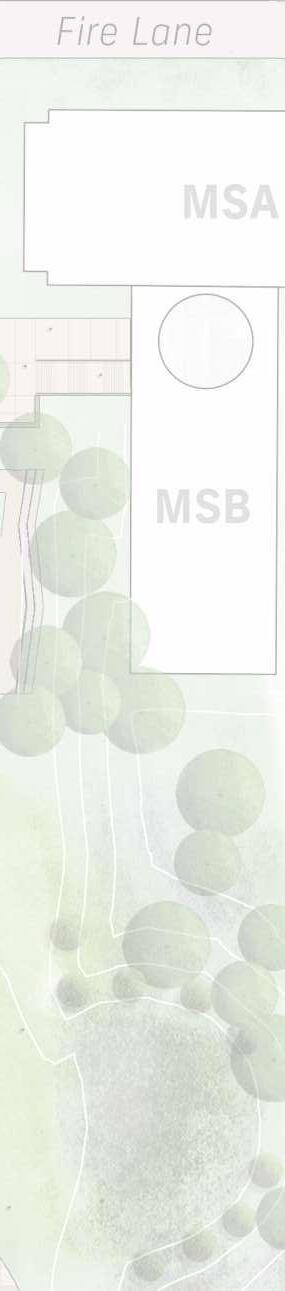
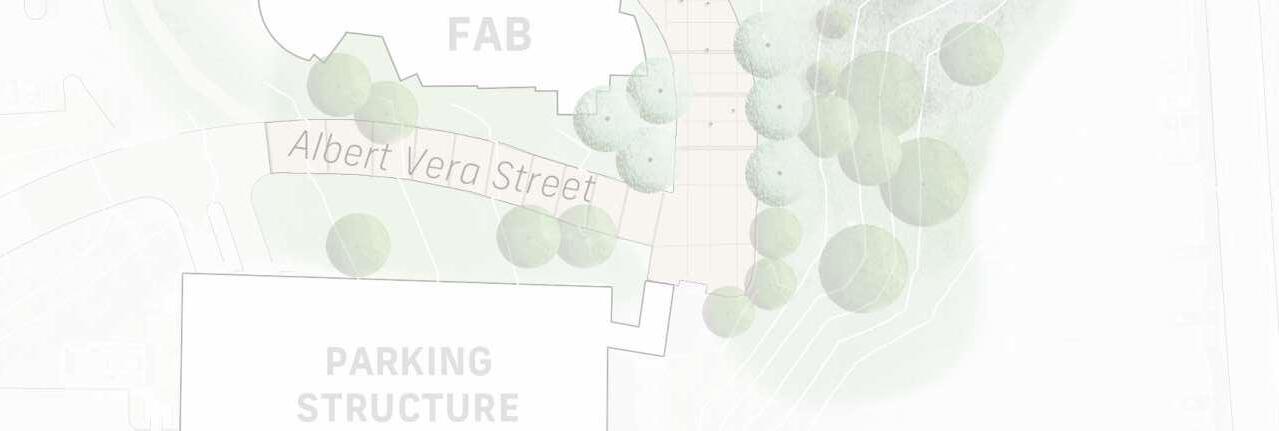
Strengthen Campus Entry and Pedestrian Framework
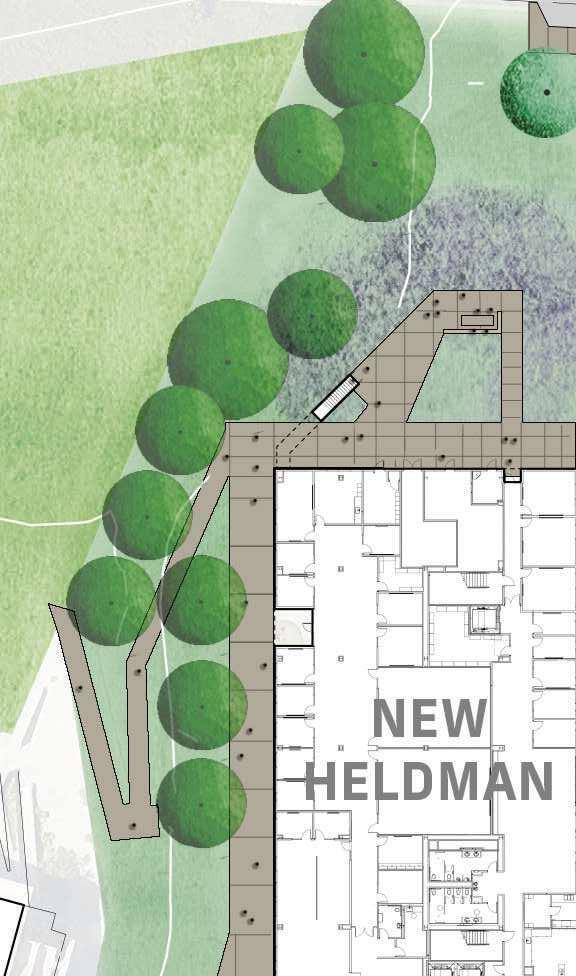
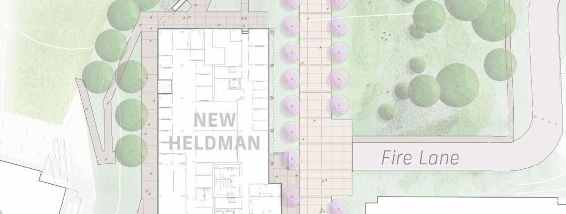
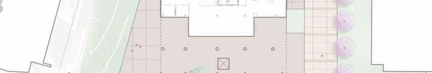
This project will strengthen the campus entryway and renew the primary campus circulation pathways including the accessible paths of travel for the North-South Wildcat Walk and the East-West Steps as recommended by the campus master plans to enhance campus connectivity and open up view-sheds to the surrounding region. The new Heldman Center should have a strong connection to adjacent exterior gathering spaces including the new Heldman Center Terrace and Vista Quad to flexibly support a range of campus activities and student life.
Create the New Heldman Center
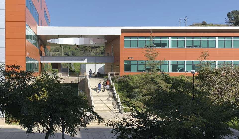
This new facility replaces the existing HLRC and includes a Student Union in addition to the Learning Center and Library functions. The building provides a dynamic complement of learning and interaction spaces that support the “whole student” in their pursuit of personal betterment and student success.
Optimize Accommodation of Relocated Departments
This project relocates numerous departments to renovated academic and administrative space in existing buildings and the New Heldman Center. Through iterative consultation with campus staff and leadership, the new department locations have been studied to provide preferred adjacency of related departmental functions, and to optimize shared facilities for efficiency, economy, and increased opportunities for collaboration.
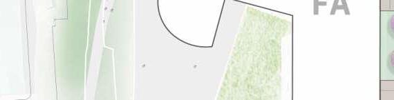
Project Components
The project will have a profound impact on the future of the campus. The overall effort envisioned by the STIR Report includes:
New Heldman Center
Approximately 69,230 GSFLACCD Project No: 09W-919.00
2.2 PROJECT PURPOSE AND GOALS
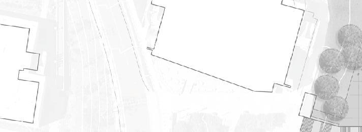
Heldman Center New Construction #09W-919.00 (Seq. 2)
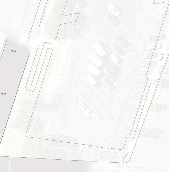
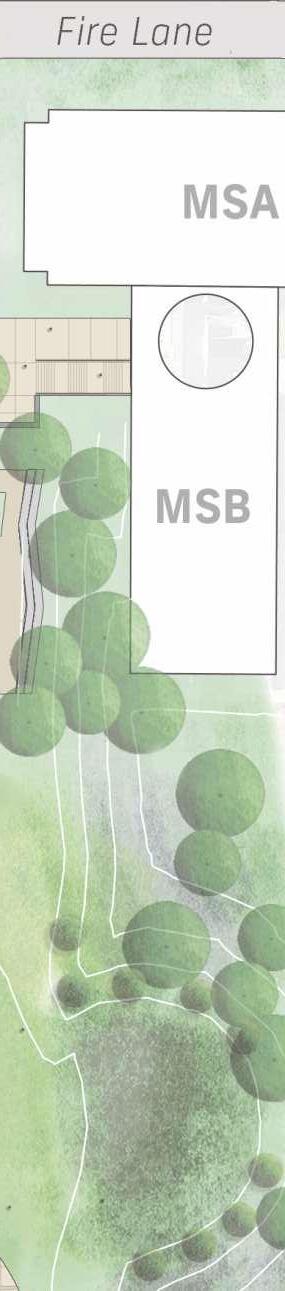
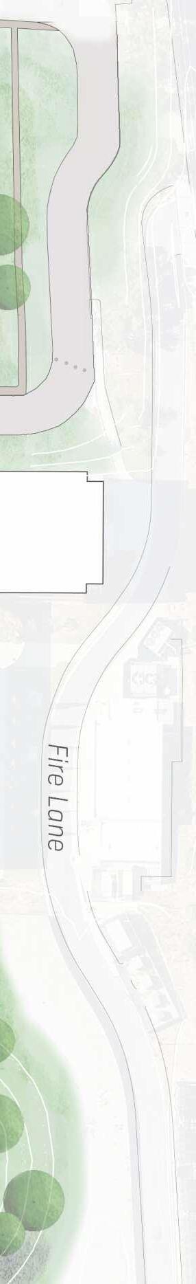
Project Limit of Work
Add Alternate NE Green Space See Chapter 6
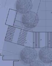
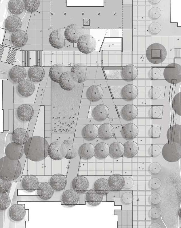
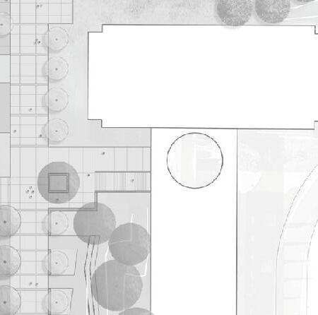
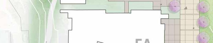
Project Scope Definition Diagram
New Dr. Morris J. Heldman Center
Scope associated with New Heldman Center
Existing Buildings
Demolition scope after Dr. Morris J. Heldman Center is Constructed (Sequence 3)
Sequence 2 Scope of Work
Sequence 3 Scope of Work
2.3 GUIDING PRINCIPLES
The foundation of planning, programming, and design for the HLRC Replacement Project is the 2019 Space Utilization Analysis and Preprogramming Report by LACCD, WLAC, and Stir Architects (Stir Report). A clear set of guiding project principles emerged from broad-based stakeholder discussions held during preparation of the Report and were reinforced at subsequent workshops. Taken together, they represent the commonly held interests and priorities of the Building User Group stakeholders:
Education & Student Focused Optimize opportunities for learning, collaborating and scholarly extracurricular and educational activities. A campus wide transformation provides a rich mix of academic and supportive programs to newly renovated spaces and the new Heldman Center which brings together the Library, Learning Center and Student Union programs. The new facility supports the needs of the whole student with a welcoming and interactive environment that promotes social and intellectual engagement.
Flexible Designed to promote seamless transition and transformation spaces for variety of user needs in pedagogy, learning, collaborating and gathering. Easily reconfigurable to support a range of activities and functions in the near-term and accommodate inevitable changes to pedagogy and physical planning needs over time.
Adaptable The building and systems will accommodate change as needs evolve. The Heldman Center shall be forward looking, providing for the needs of today while also planning for the needs of tomorrow. Building infrastructure, systems, and technology shall allow for long-term evolution. Planning solutions shall recognize teaching and space needs change and shall as such, allow for easy future modification to meet new needs as they arise. Instructional space shall support and encourage future and more progressive pedagogies.
Maintainable and Durable Design a hard-working facility that is durable and resilient and easy to maintain. The design of the Heldman Center shall be simply detailed and utilize materials and finishes that resist intensive use and environmental exposure and are easy to maintain and clean. Building systems shall be easily accessible
throughout the building for periodic upgrades, regular maintenance and replacement as needed.
Sustainable Create an environmentally friendly and sustainable facility. The new Heldman Center shall incorporate sustainable design solutions that meet the College’s baseline requirement for LEED Silver (or better) Certified and integrate LACCD’s Clean Energy & Sustainability Resolution for this project to reflect a positive stewardship of the environment through reduction of non-renewable resource use and provisions for human health and comfort. Sustainable strategies employed shall have an attractive aesthetic.
Inclusive Provide spaces that promote equity. The facility shall reflect the College’s inclusive culture; usable to the greatest degree possible by everyone and consistent with West LA College’s policies.
Welcoming Design an open and approachable campus environment where people want to be. A comfortable, accessible and secure environment where students, faculty, staff and visitors want to be is essential to the success of the project. The transformed campus environment shall provide a clear sense of arrival and provide rich variety of campus spaces supporting dayto-day activities and large campus gatherings / celebrations. The building shall be welcoming on all sides and provide a strong sense of place and arrival. Interior environments shall be naturally lit to greatest degree possible, free of glare, comfortably furnished, legible and provide a range of environments for choice.
Iconic Reinforce WLAC’s identity with a new campus heart and center of campus life and student success. The campus transformation and the design of the new Heldman Center shall reflect the vision and unique context of the College through an inspiring architectural expression. New campus gathering spaces support campus gatherings and celebrations to create memorable experiences the entire campus community.
2.4 PROJECT PROGRAMMING AND CRITERIA PROCESS
2019 Space Utilization Analysis and Preprogramming Report Framed by the Shared Governance decision-making structure of LACCD and guided by the missions of LACCD and WLAC, the College sponsored a series of Building User Group (BUG) Meetings, to solicit input from project stakeholders, including all departments impacted by the relocation activities. The college provided detailed questionnaires to stakeholder departments in 2017 to describe their aspirations and goals for the project and to outline their departments specific space needs and important functional relationships.
Project Program and Criteria Development
Moore Ruble Yudell Architects & Planners (MRY) was selected to undertake the programming of the Heldman Center and relocation projects and author the Project Program and Criteria Document (PPC). The PPC will guide the work of the selected Design-Build team that will ultimately design the buildings, coordinate the departmental relocations and construct the work. After a brief period of reviewing existing campus and project materials, MRY began the programming process with an updated reissue of the 2017 Questionnaire and the third Building User Group (BUG) meeting.
Building User Group (BUG) Workshops The BUG meeting format was enhanced to include interactive workshop exercises, and thereby deepen the engagement with the stakeholders. Individual follow-on meetings with each of the twenty-nine (29) impacted stakeholder departments brought the team and users into close collaboration. The BUG meetings presented overarching project concepts and explored the interrelationships between departments using a variety of materials and interactive activities. With campus and District leadership present, the workshops were a venue for discussion and an opportunity for the consultant team to receive feedback that informed the further development of the study. Meetings went progressively deeper into the specific space needs and functional requirements of each department.
Campus and District Leadership (CDL) Meetings
Interim small-group meetings with the President and Vice Presidents of WLAC and representatives from LACCD provided opportunities for project leadership to review progress and provide direct input into options, responses, and directions taken following stakeholder work sessions.
Decision-making Principles Our programming and conceptual planning process with the College evolved from early establishment of the ultimate purpose of the project- its impact on student experience and student success, response to the full spectrum of student learning and student needs, efficient operations, and maximizing the resources of space and funding to accomplish the project’s many goals. This list of guiding prioritiesthe ‘so-that’ of the project- was written down and displayed at each of our Building User Group Meetings to give meaningful context to our many deliberations:
• Support Student Success
• Address the whole student
• Efficient & flexible use of space
• Best use of project budget
• Equitable & accessible learning environment
Process The following outlines the highlights of the Building User Group workshops and selected Campus and District Leadership Meetings that informed the programming and criteria development of the PPC:
BUG-3 Dec 9, 2019
• Team Introduction
• Review responses the updated Questionnaire
• Review the Guiding Principles set in BUG-2
• Sticky-note exercise: list key concerns for project success
• Presentation by the team of current trends in Library and Learning Center programs
BUG-4 Feb 3, 2020
• Confirm current locations of all departments
• Review desired inter-departmental adjacencies
• Review responses to Concerns exercise
• Precedent image scoring: identify opportunities for the project to impact campus quality and student experience
• Break-out sessions with individual departments
• Discuss strategies for effective use of program space, e.g. advanced scheduling, space sharing
CDL Meeting Feb 20, 2020
• MRY asked to explore reconfiguring the
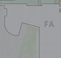
Heldman Center program to be more “student focused” by replacing the Learning Center, Math & Writing Labs, Teaching & Learning, Faculty Development, Career Connection, Distance Learning and Academic Senate with the Veteran Center, Student Health and Basic Needs programs.
• The displaced programs were to be located in Fine Arts - B
BUG-5 Mar 9, 2020
• Review campus and site organization concepts
• Review results of Opportunities exercise
• Review and comment/confirm overall program relocation based on CDL Meeting revised strategy- 4 and 5-story schemes presented
• Break-out sessions with individual departments
• Overall BUG preference to have the Learning Center in the new Heldman Center
CDL Meeting Mar 12, 2020
• Follow-up review of proposed relocation and programs allocated for new Heldman Center
• Discuss/reconsider the alternative program with student services in Heldman and Learning Center moved to FA-B
NOTE: During the study, the COVID 19 pandemic emerged and the State of California adopted the Safer at Home policy, making previous face to face interaction with stakeholders no longer prudent or possible. To maintain valuable momentum and meet the schedule, the consultant team relied on a range of technologies to continue development of the study and to interact with stakeholders and campus/project leadership. All subsequent meetings, including BUG-6, BUG-7, and BUG8 were held using Zoom video conferencing technology. Additional campus engagement was also accomplished using video technology including: (4) Town Hall presentations and multiple Specialty Subject Matter Meetings.
CDL Meeting Mar 26, 2020
• Confirm Heldman program re-locating Learning Center in the new building
• Blocking and stacking of Heldman Center became the basic scheme, with further studies of programming for FA-B, Student
Services, and Math & Science-A buildings
BUG-6 Apr 6, 2020
• This meeting and break-out meetings were virtual, using Zoom.
• User Group review of program locations in all buildings.
• Detailed review of individual department space allocation and layouts
• Review pros and cons of 4-story vs 5-story schemes; 4-story approach validated
Town Hall April 15-16, 2020
• Presentation of findings open to all project and campus stakeholders
• Reviewed the department relocation strategy.
• Presented preliminary planning concepts for the Heldman Center and other building renovations.
CDL Meeting Jun 22, 2020
• Review of critical space allocation and location/adjacency concerns of 14 departments prompted the team and project leadership to revise the workplan and process to allow more detailed input and study of alternative solutions.
• This meeting confirmed the new strategy, scope, and process going forward.
CDL Meeting Jul 7, 2020
• Confirm detailed issues and potential solutions for each of the affected 14 departments identified for the reprogramming study
• Preparation for BUG 7
BUG-7 Jul 13, 2020
• Detailed review of concerns from all 14 affected departments
• Break-out sessions with individual departments to further review alternative locations and potential layouts
• Validation of program spaces and locations, studies of layouts
• Clarification of adjacencies, interdepartmental functional relationships, and space sharing
• Final detailed input from each department to reach consensus on blocking and stacking for all buildings, and illustrative layouts of
program elements
Town Hall Jul 19-20, 2020
• Presentation of findings open to all project and campus stakeholders
• Review of draft program, blocking and stacking, and illustrative departmental layouts
• Detailed review of each of the 14 departments
• Consensus approval with some smaller comments to be incorporated in the final draft
BUG-8 Jul 27, 2020
• Review of Exterior and Interior architecture and character, potential materials, principles, and precedents
• Five exterior principles: Context, Scale, Identity, Functional Expression, and Engaging Public Realm
• Eight Interior principles: Accessibility/ Universal Design, Acoustics, Daylight & Lighting, Security, Serviceability, Sustainability, Visibility & View, and Way Finding
• Discussion of selected types of spaces in the new Heldman Center
• Precedent images for all of the principles and spaces
• Process included 7 live polls with the User Group to prioritize principles and goals
CPT-PMO Feb 15, 2024
• Review of Roles and Responsibilties for Criteria Architect and Bridging Documents Architect.
• Review of Sequencing including pre-
project planning for Campus Low Voltage reconfiguration.
PPC and Design Review Feb 29, 2024
• Coordination of Campus Low Voltage connections to new Heldman Center.
• Technology Sequencing Diagrams Review.
AHU Review Mar 14, 2024
• Review of Air Handling Unit options.
• Consensus for 2 AHU solution established.
CPT-PMO Apr 4, 2024
• Review of updates Technology Sequencing.
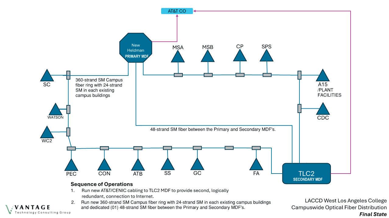
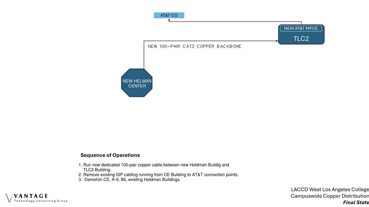
• Heldman MDF connections review.
CPT-PMO May 2, 2024
• Heldman Design objectives review.
• Updated Campus Low Voltage requirements reviewed.
• Review of Freight Elevator Roof Stop.
The overall distribution of programs in the project is shown in section 4 “Campus Relocation Strategy Diagram”. In preparing the Final Draft PPC all User Group space allocations and illustrative layouts were cross-checked against overall project scope guidelines from the Stir Report. User Groups were reminded that illustrative layouts, blocking and stacking, and even general locations shown in PPC graphics do not represent a final design, which will be undertaken by the selected Design-Build Entity.
Bluebeam Studio, a software program, was used to solicit review comments from project stakeholders and to conduct quality assurance reviews by the combined consultant team.
2.5 THE PPC: GOALS, GUIDELINES, AND MINIMUM PROJECT REQUIREMENTS
The PPC presents critical project information to describe program, planning, and overall project intent, and to set forth minimum project requirements. Complementary information is provided in each of the sections as follows:
Goals Section 2 provides narratives to describe overall project purpose and intent, high-level project components, guiding principles, and an outline of the process of programming and criteria development.
Guidelines Section 3 defines the Project Vision with a set of principles and key concepts that serve as guidelines to describe campus and District priorities for the project. Project scope is outlined in graphics and narrative. Information on Campus Context and Site provides a guide to be further informed by survey information available through the BuildLACCD website.
Requirements Codes and Regulations and Reference Documents in Section 3 set minimum standards for project elements. Section 4 provides building by building detail on program requirements, including Room Data Sheets. Section 5 Design Criteria further defines minimum performance and/ or prescriptive requirements of site and building systems and components.
The Design Build Entity (DBE) shall use this document in combination with all LACCD District Standards, Campus Standards, and other reference documents including but not limited to those listed in Section 3.6. The DBE shall review reference documents in their entirety and perform the work with the requirements set forth in them. Conflicting or incomplete information shall be reviewed with WLAC and LACCD, consistent with Deviation/Exemption process, to ascertain if additional information is available, and/or to request clarifications as needed. This PPC may describe program requirements not specifically covered in the reference documents, as well as identify specific deviations from the District and Campus Standards, if any. Throughout the course of design and construction the DBE is expected to further gather, investigate, and refine the requirements illustrated herein.
2.6 SCOPE OF WORK
This Project Planning Criteria (PPC) document serves as the basis of design for the Dr. Morris J. Heldman Center Project (DMJHC). For the purpose of this Document, Dr. Morris J. Heldman Center is also referred to as “New Heldman Center”. See Chapter 06: Additive Alternates for additional info.
The Scope of Work for this PPC is limited to Sequence 2 only. Sequence 3 will be by others.
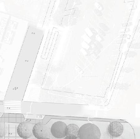
LEGEND
Area of Work - Site
Approximate location of DMJHC
Area of Work - Future Demolition
Completed Scope - Building
Completed Scope - Site
Additive Alternate
Sequence 2 - Construct New Heldman Center
Sequence 3 - Demolish HLRC and Restore Site
3.1
VISION AND KEY CONCEPTS
Design of the new Dr. Morris J. Heldman Center (DMJHC), and the renovated and remodeled spaces, is guided by a core vision: a transformational project that will positively impact student experience and success, advance sustainability, and foster an inclusive, supportive environment for students, staff, and faculty.
VISION: A NEW ACADEMIC CORE DEVOTED TO STUDENT SUCCESS
The New Heldman Center shall integrate its multiple components to be greater than the sum of its parts. New and relocated programs are to provide a continuity of academic and student serving functions that are easily accessed and welcome student use. Transformation of the ‘upper terrace’ and its main North-South plaza is a key organizing element. The New Heldman Center is to be fully connected and oriented to this major campus spine.
Specific elements of the Vision are derived from the initial guiding principles of the project’s early stakeholder engagement:
Student Empowering
The new Heldman Center is a student focused facility. Its Library, Learning Center, Student Union/ ASO spaces shall maximize student choice,
access, and use at all times.
Welcoming / Accessible / Inclusive
Students, faculty, staff, and visitors shall immediately experience clarity and celebration of arrival and movement into the campus. Circulation into and within the New Heldman Center, and the re-planned campus area around it, shall provide ease of way finding and access using Universal Design principles. The New Heldman Center should welcome its users with clearly visible sequences of movement, daylight, and lighting, supported by appropriate graphics.
Sustainable
Consistent with WLAC’s Climate Change Program, the project shall advance LACCD’s Clean Energy & Sustainability Resolution on the campus through high standards for building and site performance, taking advantage of visible systems wherever possible for student and community information and learning.
Flexible / Adaptable for New Technologies
The new Heldman Center’s building systems shall be systematically organized with modular planning that support ease of access, maintainability and adaptable to change.
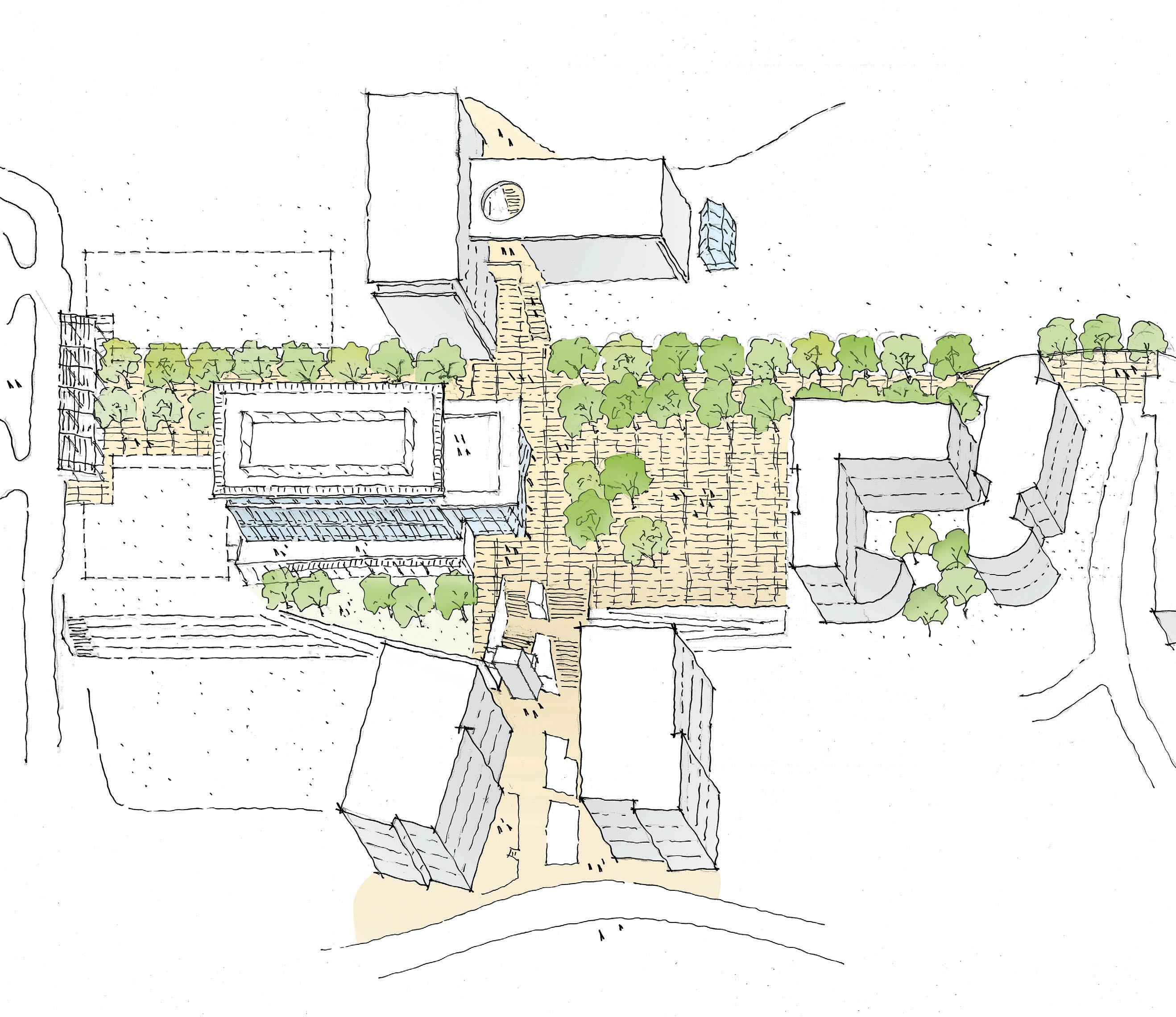
Project Overview Diagram
PROJECT
3.1 PROJECT VISION AND KEY CONCEPTS
Safe and Secure
Design shall provide controlled and zoned access to the Library and other functions to enable afterhours events while securing adjacent programs. The design shall anticipate emergency events and create areas of refuge on each floor.
Operationally Efficient
Cost of operations and long-term serviceability shall guide material and systems choices. Provide adequate space for access to maintain building systems. Design and detail the building envelope, including fenestration and shading, to respond to solar orientation and reduce HVAC loads.
Contemporary and Contextual
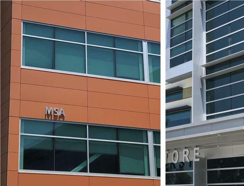
The campus architectural context presents a variety of contemporary design influences. Examples of precedents provided in Sections 3.2 and 5.3 describe a range of materials, colors, and features that help integrate the new Heldman Center with the best aspects of WLAC’s physical environment. In general architectural expression shall derive from climate-responsive features, careful scaling and proportions, and patterns of interior function.
Identifiable
and Memorable
The design may make use of color, materiality, lighting, and graphics to accentuate the presence of the New Heldman Center as the heart of the campus and its single most important facility for student engagement and success. Identifying WLAC with signage at or near the top of the building has been noted as a specific campus goal.
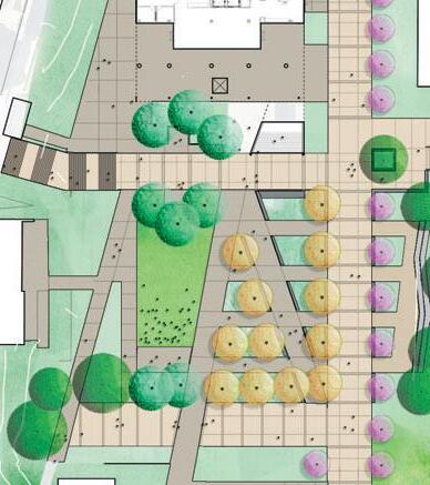
VISION: A REVITALIZED PUBLIC REALM
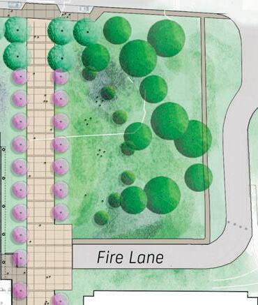
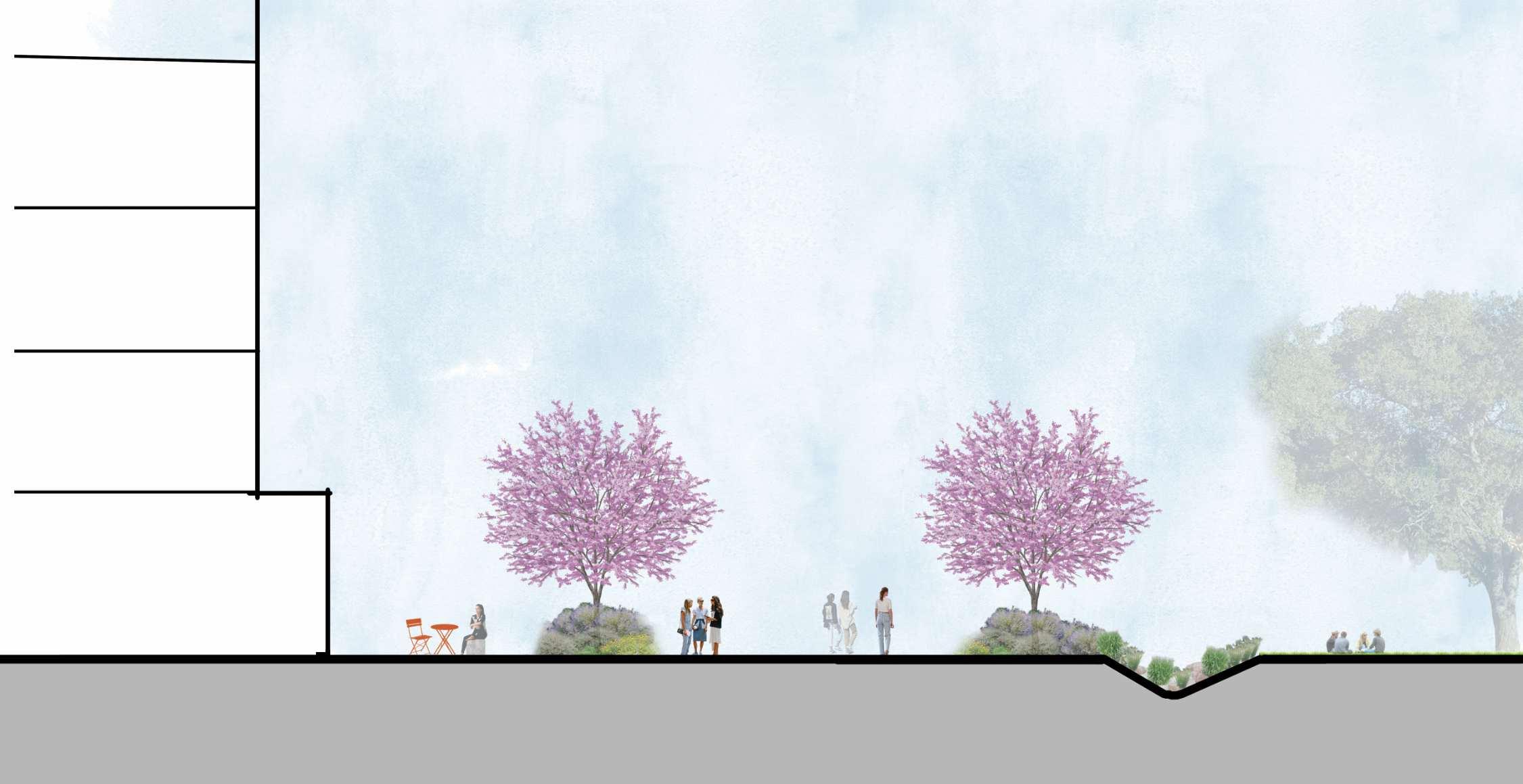
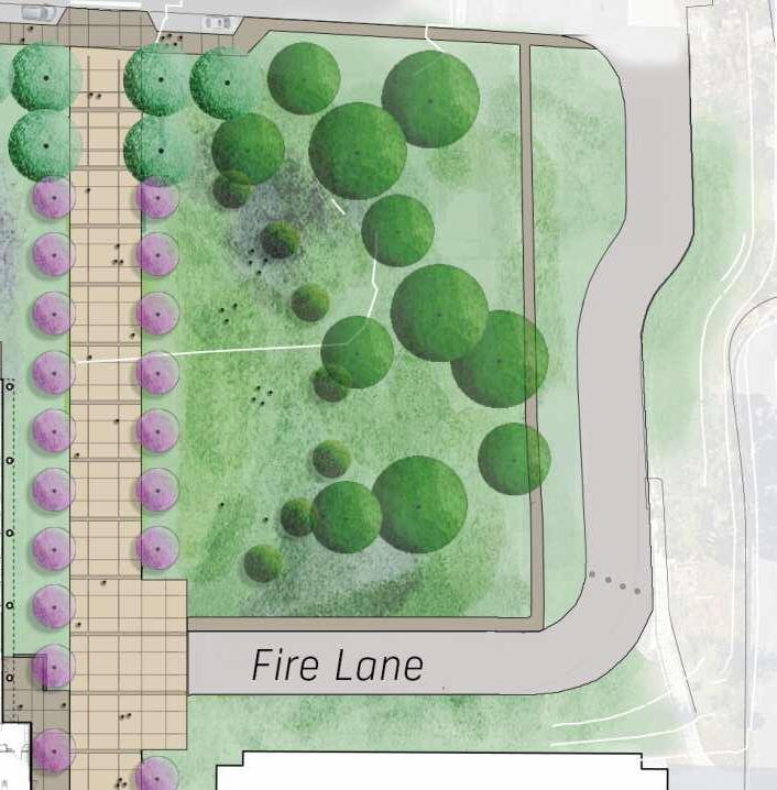
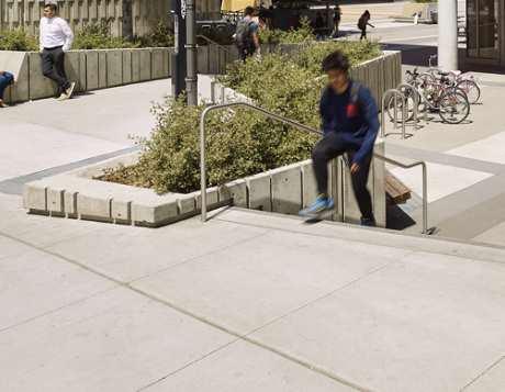
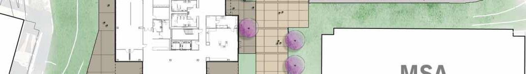
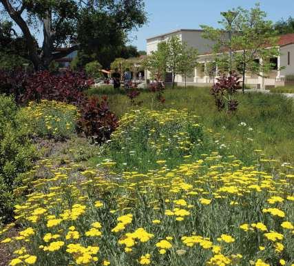
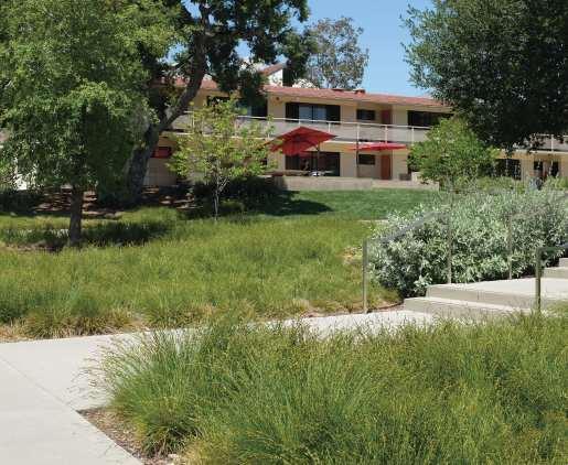
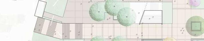
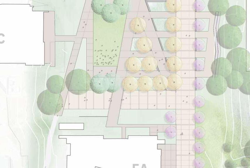
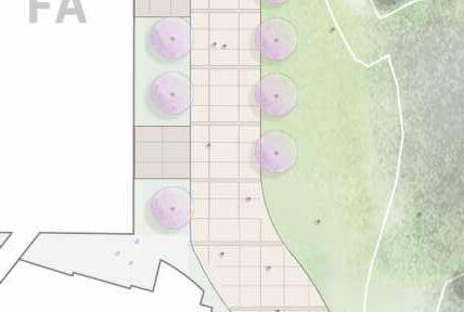
A core priority of the project is transformation of the public realm in all affected areas of the campus. Like the New Heldman Center itself, the revitalized campus open space should invite everyday use. Landscape design should highlight habitable, user-oriented place-making, with simple, easily maintained materials and furnishing. Specific priorities include:
1. Activate Campus Environment and Building Ground Level
Student and community use of the campus public realm should be supported by open, visible interior activity at the ground floor of major buildings
such as the New Heldman Center. Functions that benefit from controlled exterior access flow out to terraces and courts. The café function of the PAWS shop can provide an outdoor gathering place that revitalizes the North-South Wildcat Walk at the Heldman Center entry.
2. Respond to Existing Campus Scale and Massing
Proportions of open space and relationships to adjacent buildings should guide building massing, the articulation of building scale, height, and bulk.
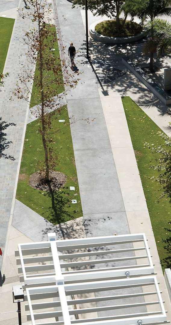
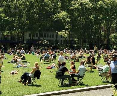
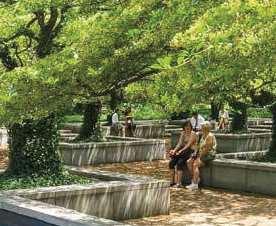
3. Create Shaded /Comfortable Outdoor Spaces in a Park-like Setting
Tree planting, shade structures, pavement design, lower scale planting, and outdoor seating should all contribute to an open campus environment that offers a complement to the embrace of buildings and relief from interior space experience.
4. Provide Access to Views
The opportunity of views toward hills and mountain ranges to the north and west of the campus provide a strong sense of place and regional identity. Building placement and the use of upper level terraces should take advantage of this important feature of WLAC’s campus location.
5. Strengthen Campus Framework
Continuity of open space is a tremendous challenge with the current layout of buildings and circulation. New extensions and openings of space now occupied by buildings to be demolished presents an important opportunity for clarity of plan, space, and movement on the campus. New areas should improve visual and movement connections to existing campus entrances, paths, and building entries. Alignments of building fronts and resolution of topographic breaks and sequences with more visible, accessible routes is a high priority for the campus.
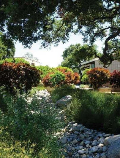
Low-water use, site hydrology, and ease of landscape maintenance are key concerns for all new site improvements. Using a native and adapted plant palette and contemporary irrigation systems, supported by ease of access to planted areas and protection from high-traffic flow are all guiding priorities to be demonstrated by the landscape design.
3.1 PROJECT VISION AND KEY CONCEPTS
PROJECT VISION: 8 PRINCIPLES TO GUIDE DESIGN
FLEXIBLESUSTAINABLE
3.1 PROJECT VISION AND KEY CONCEPTS
LEGEND
Campus Gateway
Limit of Work
Academic Core Gateway Seq 2 Seq 3
Vehicle Circulation (Proposed vehicle entry/drop-off loops - not in project scope)
Pedestrian Circulation
Academic Core
Additive Alternate
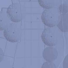
Campus Framework Diagram
• Strengthen and Clarify Vehicle Arrival and Hierarchy of pedestrian movement
KEY CONCEPTS
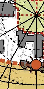
1. A Campus and Community Lantern of Learning
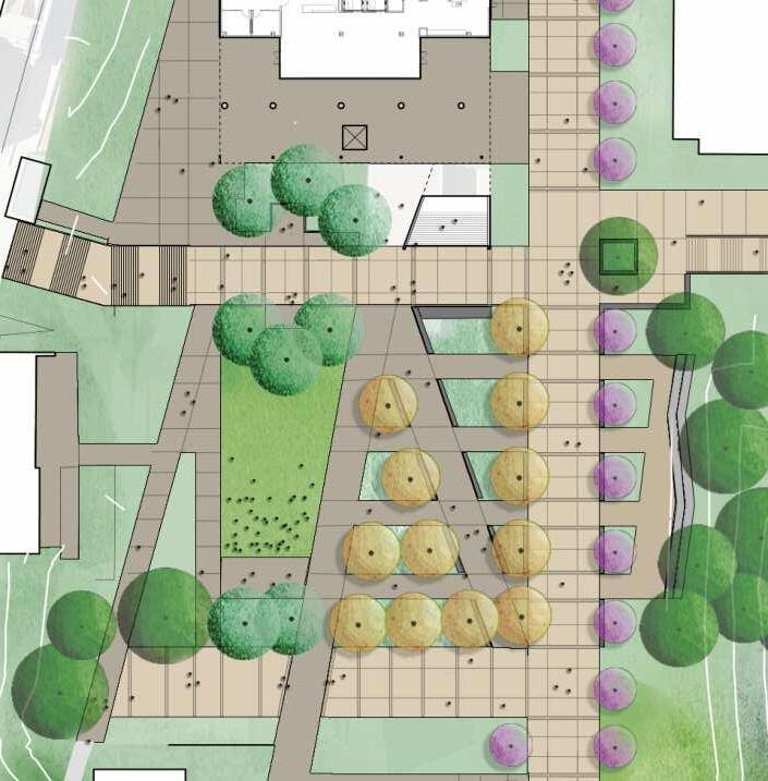
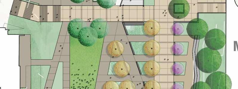
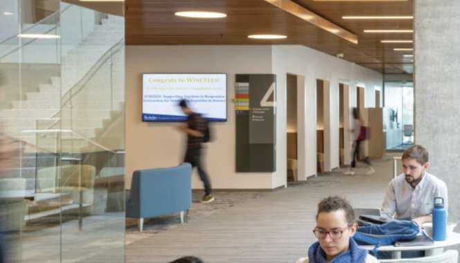
New Heldman Center’s location at the “top of the stairs” and the center of the main upper level places it in an excellent position to mark the campus with a beacon of student and community life. Its visibility announces WLAC identity and may be further significant with appropriate graphics. The entry lobby of the Center has the opportunity to engage the larger context with a grandly visible space that puts student life and learning on display.
2. A Student-oriented Campus Center
New Heldman Center will be a place for students. The cumulative options of Student Union, Library, and Learning Center provide a spectrum of settings to study, collaborate, socialize, and recharge.
3. Supporting Faculty Excellence
A suite of spaces for faculty in Heldman Center provide a new nexus of resources, collaboration, and respite between classes.
4. Shared and Multi-use Spaces
With the goal of maximizing the use of the project’s new and remodeled facilities, WLAC and the Programming team devoted considerable time to understand the opportunities for programs to share space. Many departments are moving from over-sized but inefficient facilities in outmoded buildings into new or renewed quarters that must meet current District guidelines for efficiency. Shared reception and conferencing/collaboration spaces became the key to giving each department adequate space within project limits. Program adjacency also presents opportunities for staff to work efficiently and in collaboration with colleagues.
5. Connect and Expand Programs with Outdoor Space
Another measure to maximize the effectiveness of the project scope is the use of adjacent outdoor area- either shaded arcades or upper-level terraces with controlled access.
6. Zoning Activities in the New Heldman Center
Blocking and stacking of New Heldman Center responds to functional characteristics of different program areas- noisy vs quiet, open vs controlled. Placing the Library program essentially on the second and third floors was one key example,
allowing access control and a quieter environment. Assembly rooms on the fourth floor take advantage of a view terrace, carrying one popular feature of the existing HLRC into the new Center.
7. A Clarified and Connected Campus Framework
A vast amount of site work will redefine the campus appearance, will support the WLAC commitment to sustainability, and mitigating climate change. The number of new and/or upgraded campus landscape elements combine to dramatically improve campus connectivity, accessibility, and way finding:
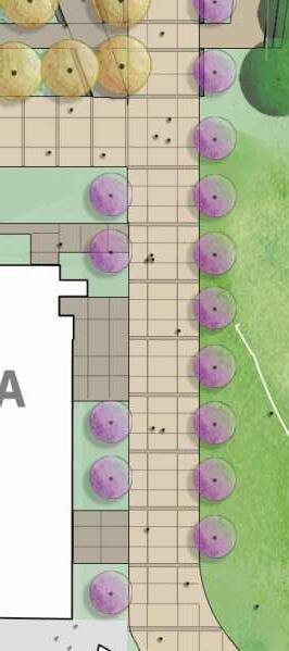
• A new North Pedestrian Entry to mark arrival from parking areas to the north.
• Existing North-South Wildcat Walk upgraded with shade trees and selected paving improvements.
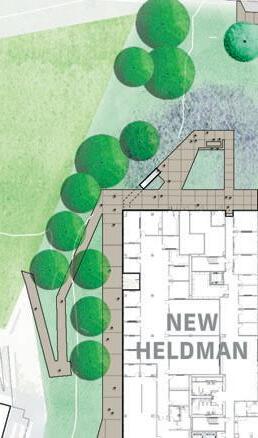
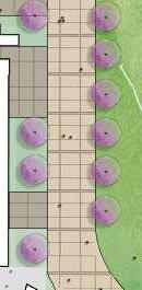
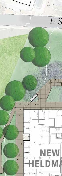
• A new central campus Vista Quad at the current HLRC site
• An improved East-West stair and ramp sequence linking the B Street bus stop and midlevel courtyard at the Student Services Building to the new Heldman Center, new central Vista Quad, and upper terrace.
• The design of these new and renewed campus public spaces shall integrate with the Campus Accessibility Framework to maintain and enhance universal access for all members of the campus community.
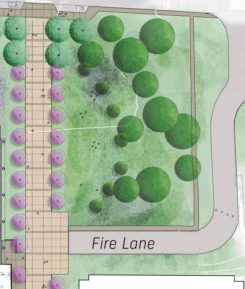
• Updates to the campus framework shall continue to support code mandated access for emergency vehicles as well as controlled access for vendor and maintenance staff vehicles - screened parking for facilities vehicles shall be integrated in the landscape and building design.
3.1 PROJECT VISION AND KEY CONCEPTS
Existing Ramp Part of General Classroom Project
2 Existing Bridge
3 Existing Vertical POT
4 Existing POT to Baseball Restrooms
5 Existing POT to Freshman (Public Right of Way)
6 Existing POT
7 Existing POT Part of Project A#114706
8 Existing POT Part of Sequence 2 DMJHC
ACCESSIBILITY LEGEND
Accessible Path of Travel Sequences 2 and 3
Limit of Work
Campus Topography (Diagrammatic)
Elevators
Accessible Parking
Public Transporation Ride-Share Access
Campus Accessibility Framework
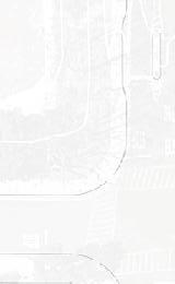
3.2 WLAC CAMPUS CONTEXT
Location: West Los Angeles College (WLAC is centrally situated to serve the Westside communities including Baldwin Hills, Beverly Hills, Brentwood, Century City, Crenshaw, Culver City, La Tijera/Windsor Hills, Marina del Rey, Mar Vista, Pacific Palisades, Palms, Playa del Rey, Venice, Westchester, West Los Angeles, and Westwood. Given its location, and proximity to the Westside and Metro Expo Line Corridor, level of transit service and community connectivity, WLAC is well-positioned to serve these communities as they grow.
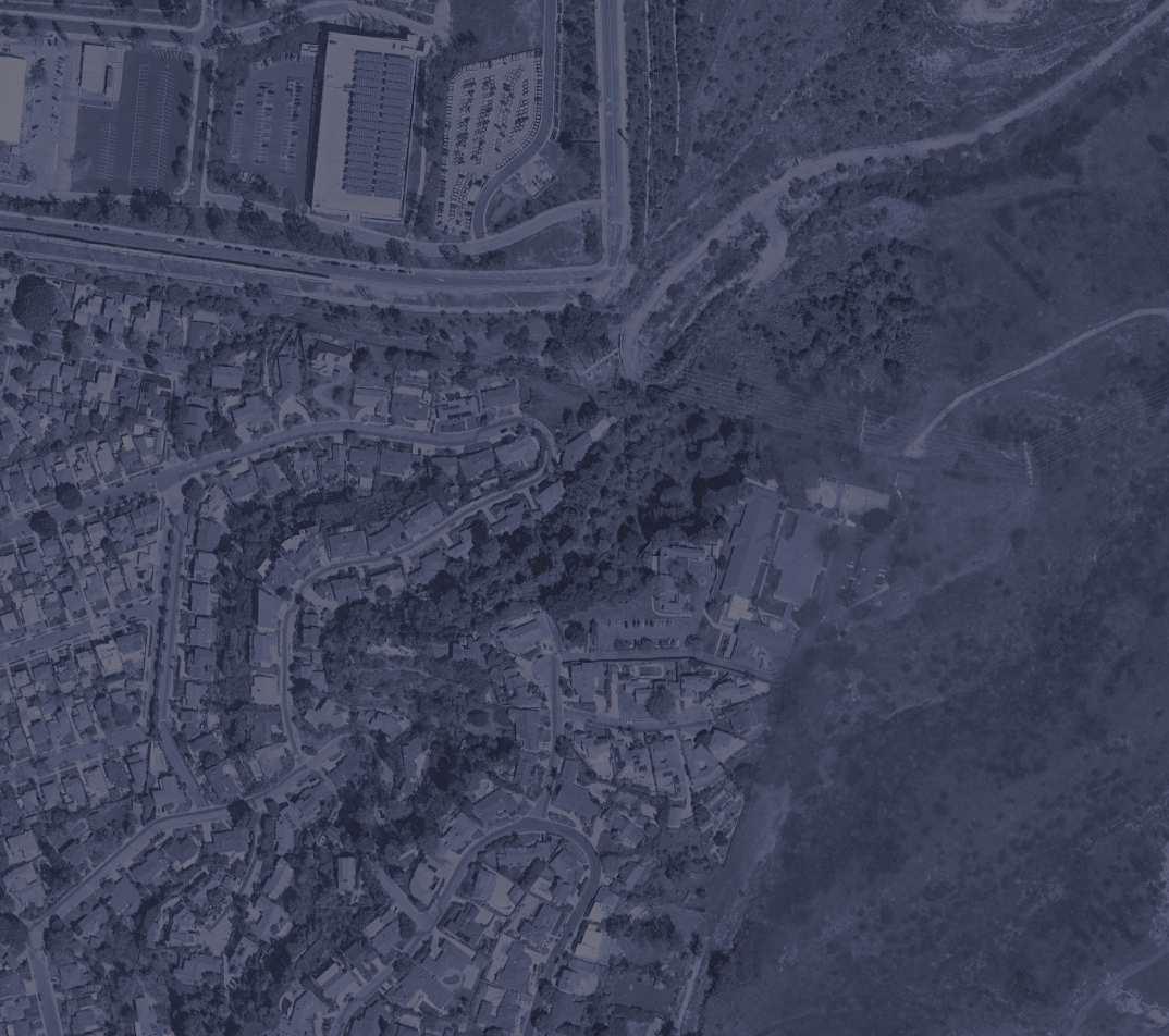
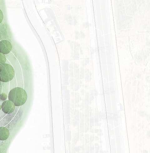
Setting: The West Los Angeles College (WLAC) campus is perched above Culver City on the rustic western slope of the Baldwin Hills with panoramic views spanning from the Hollywood Hills to Marina del Rey and the ocean beyond. The campus has open space edges along the north and east boundaries with the Baldwin Hills and slopes from the east to west campus. The WLAC campus has suburban edges along the western and southern boundaries with neighboring single family and multifamily residential communities. These neighborhoods create a buffer with major arterial roadways and lend a secluded feel to the campus.
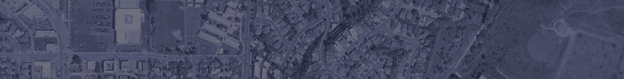
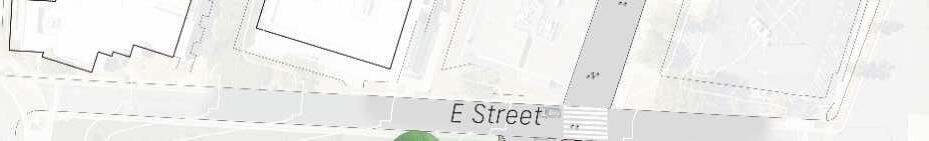
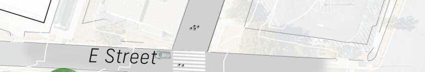
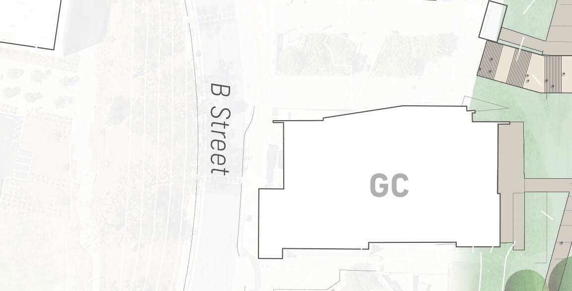
Campus Access and Arrival: The two principal campus entries are located on the northern edge of campus and the south-west corner. The northern access is from College Boulevard by way of Jefferson Boulevard, a major regional artery. The south-west entrance is from Freshman Drive by way of Overland Avenue, another regional artery. The campus is bounded by Freshman Drive to the west, Sophomore Drive to the north and east and Stocker Street to the south. Only Sophomore Drive, along the eastern edge of campus, has any direct connection to the academic core.
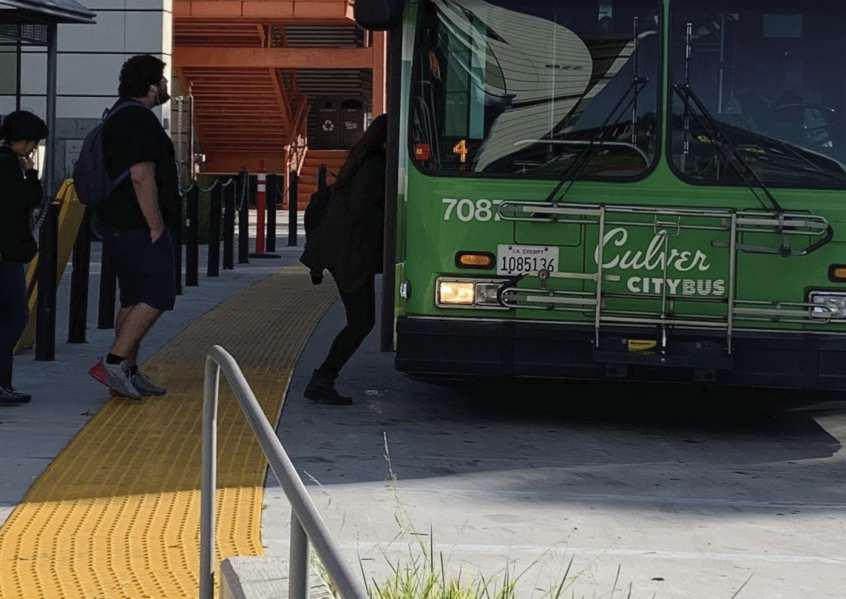
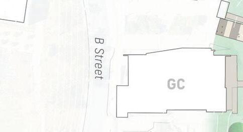
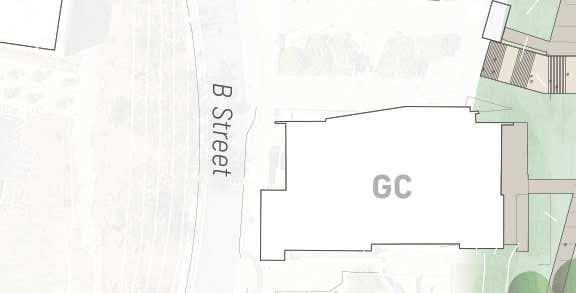
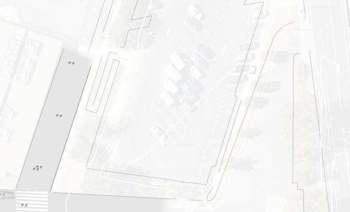
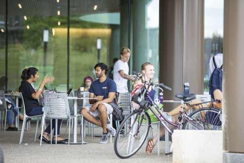
Students, faculty and staff principally arrive to campus by personal vehicles or public transportation (bus). There are limited pedestrian or bicyclist arrivals. Vehicular parking is provided on surface lots or in the South Parking Structure. A Metro Bus stop is located on B Street at the courtyard between the General Classroom and Student Services Buildings. Bicycle parking is distributed around the campus.
Site: Hillside topography is a defining feature of the campus, providing views and access to cooling ocean breezes. The campus is situated on three
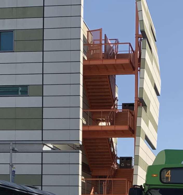
Lower Campus Bus Stop on B-Street
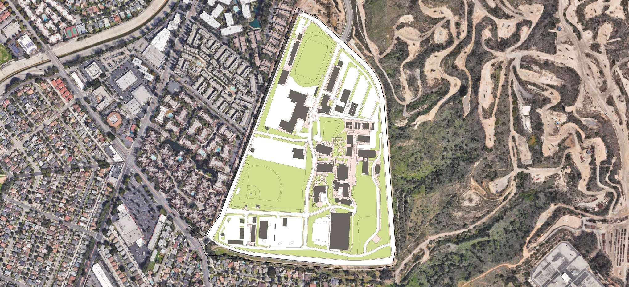
principal terraces stepping down to the west. The lowest terrace comprises athletic fields and campus support facilities while academic structures are predominantly located on the upper two terraces where views are available. Parking is provided on all terraces roughly in proportion to the uses served. The existing campus circulation framework loosely connects campus development across the significant topography of the terraced campus. The campus is 68 acres with significant undeveloped areas of sloping and landscaped open space.
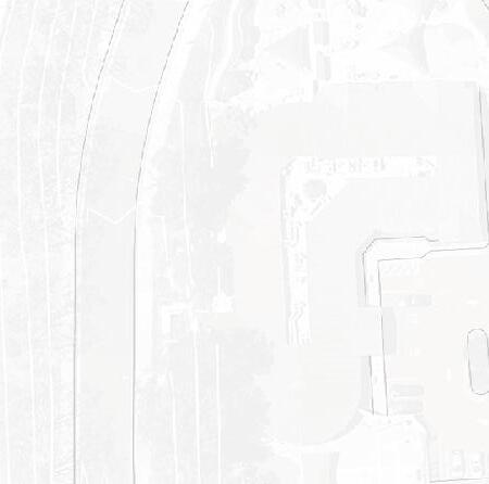
Buildings: The campus has grown incrementally over time, beginning with the first buildings, the “bungalows”. The most recent buildings include Math & Science Buildings A and B, Student Services Building, and the General Classroom Building. The campus has retained and continues to use all of the original structures with varying degrees of utilization and they are expensive to maintain and operate. As such, the bungalows and several other aging buildings slated for demolition have exceeded their service lives and no longer provide quality learning and working environments.
Experiential Quality: At present, the campus lacks a strong sense of identity, and feels remote from the surrounding community. The campus entries are underdeveloped and physically removed from the academic core by a buffer of parking along the north and south edges and athletic fields to the west. Within the campus, the terrace levels are visually separated with no strong pedestrian links up and down the hillside. Additional planning is needed to optimize vehicle arrival patterns and campus circulation in general. Nevertheless, the New Heldman Center seeks to address some of this discontinuity and improve safety and way finding with improvements to key entrances and circulation elements. These are described in Section 4.2.
DESIGN CONTEXT OF BUILDINGS
Defining the relevant context of architecture and open space will be a key challenge for interpretation by the College’s chosen Design-Build team. Contextual character should be a significant influence on scale and massing, exterior envelope systems, materials, and colors, hardscape, and planting palette. However, the campus does not
currently present a coherent framework for such choices, and cues for new design must be carefully sifted from the ‘mixed bag’ of the existing fabric. Significantly, the overall scope of the project presents an opportunity to take existing ‘best case’ examples as points of departure and create the building and landscape context of the future with strong, consistent development of a compelling concept. As a guide, the PPC includes selected views of buildings and spaces. Given the extent of demolition- especially of the existing HLRC, the largest building on campus- examples are for the most part drawn from the most recent additions to the campus.
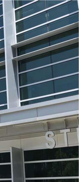
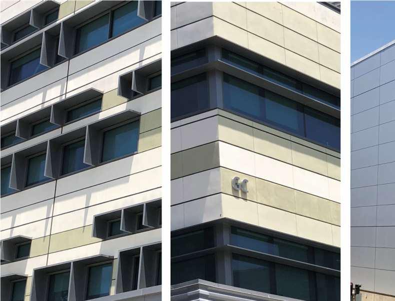
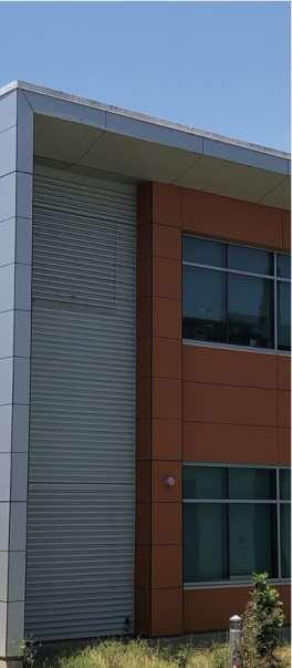
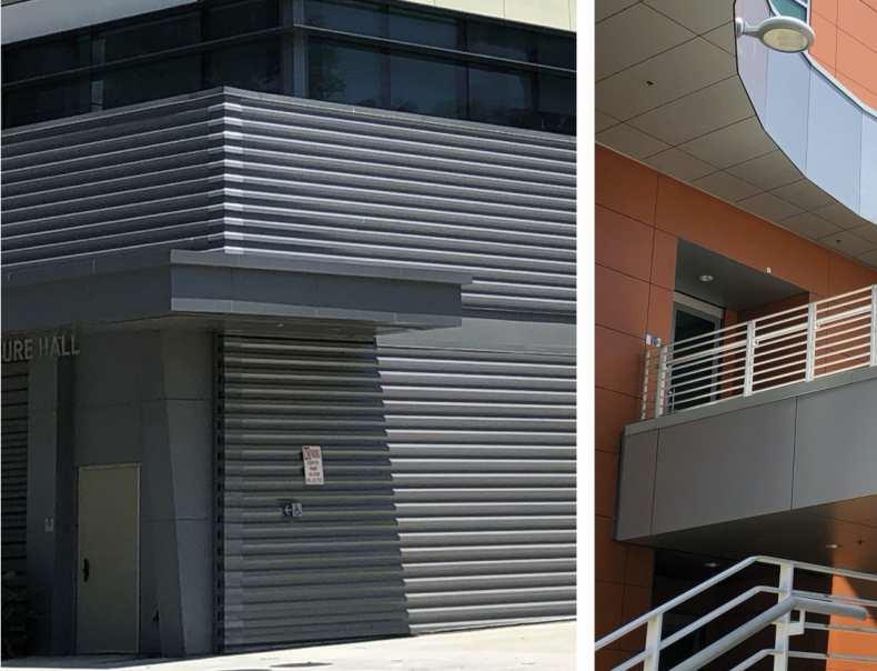
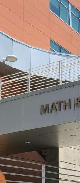
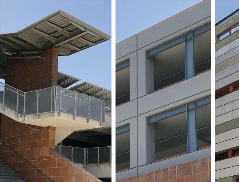
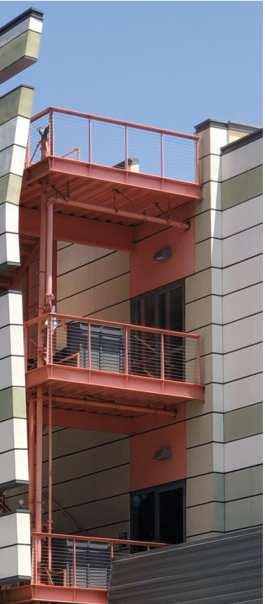
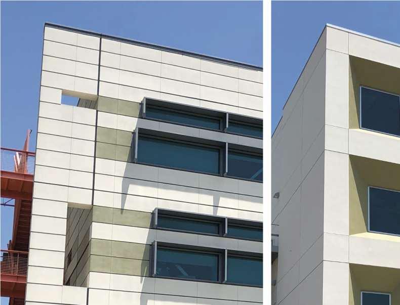
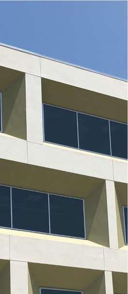
Math and Science Building: Completed in 2004 the building’s exterior is highly disciplined, with a thoughtful mix of materials related to ground level vs upper floors and long main elevations vs narrower end elevations. Its covered, raised terrace and bridge link two wings under a dramatic if not very functional canopy. Math and Science offers the most likely palette of material types, if not actual colors and combinations: stucco, exposed concrete, and flat and corrugated metal panels. The clarity of its two-part massing and the overall usage of materials is successfully straightforward and unpretentious.
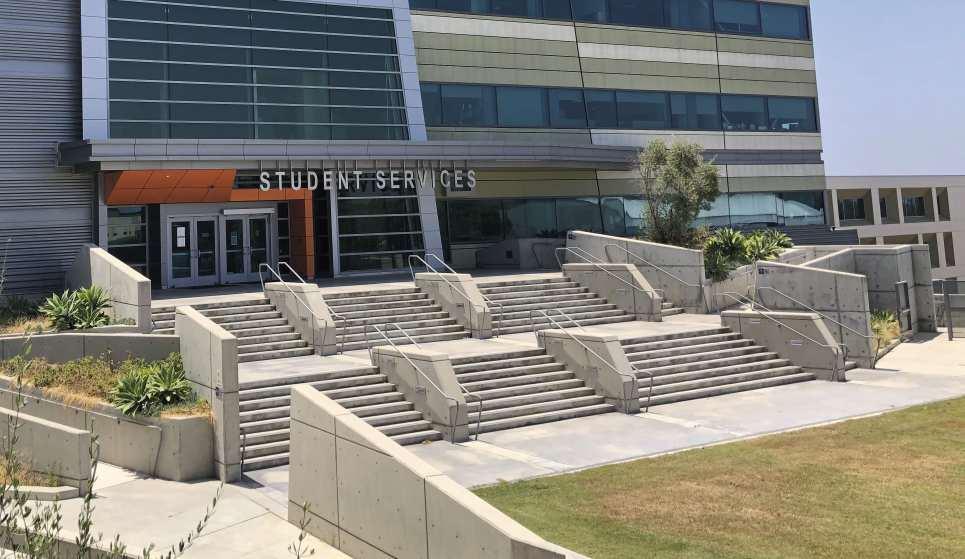
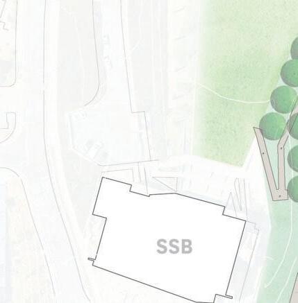
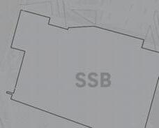
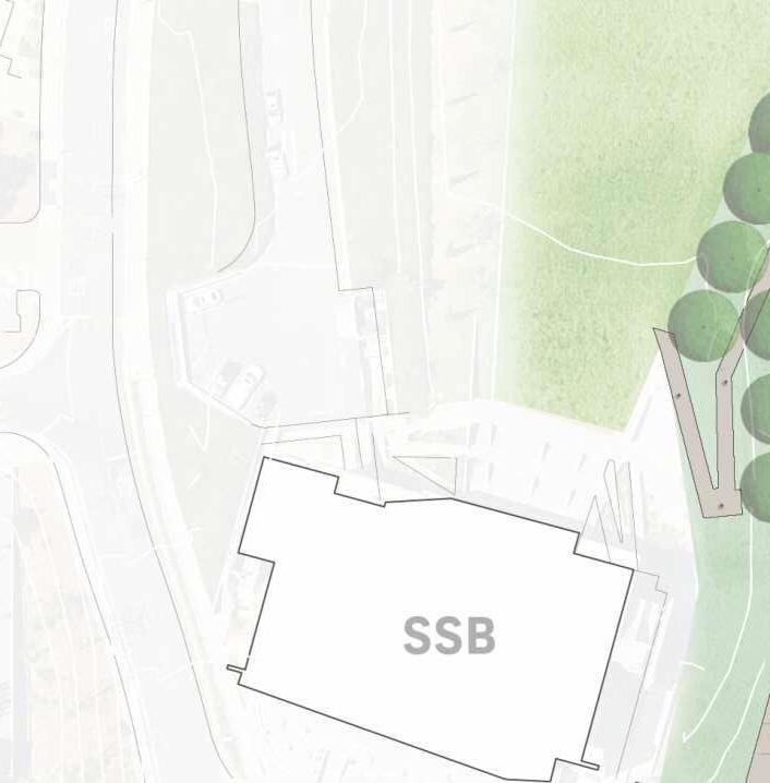
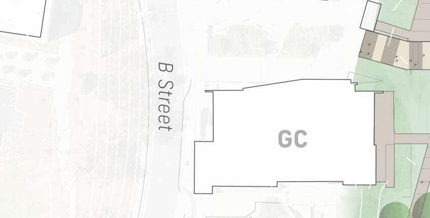
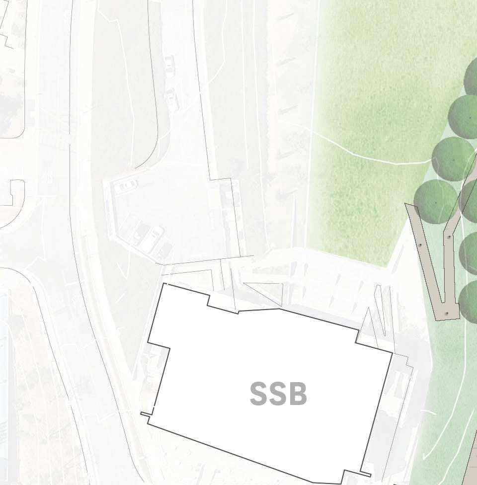
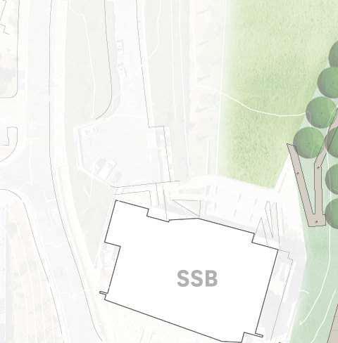
Student Services (SSB) and General Classroom (GCB) Buildings: This pair of more recent additions frames a nicely proportioned, middle terrace courtyard that is unfortunately not visually connected to the upper terrace. The architecture follows the principle of ‘techtonics’ in which the building envelope is articulated into a series of discrete elements— floating upper walls, exposed stairway structures, ground-connecting base walls, intersecting slotted windows, etc. all of which dramatize the sense of an assembly of parts. Color choices highlight the separateness of the elements. These buildings primarily work as a context because there are two of them, helping the design to look less idiosyncratic. With strong associations to a specific time period, the overall design character still provides some limited influences.
Technology Learning Center (TLC): Located on the lower terrace level and rising vertically up to the middle terrace on its west side, the newest building on campus reads as a simple cube, with some light sculpting of discrete window surrounds
as a random composition, all in stucco. Its colors are subdued but compatible with the adjacent SSB and GCB structures. The potential connection to the SSB-GCB courtyard was ignored in its design and the building seems isolated despite its proximity. Anecdotal opinion on campus seems to rate this new addition as at best a moderate success, and not a model to be emulated. With their disparate qualities, this quartet of recent buildings will be the immediate ‘partners’ to the New Heldman Center, and should be carefully considered in varying degrees as influences within the design context.
DESIGN CONTEXT OF OPEN SPACE
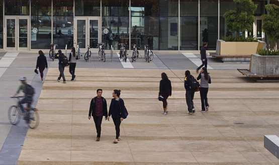
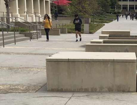
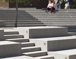
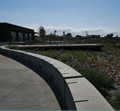
The public realm aspect of the existing WLAC campus offers even less coherent influence than the built environment. At present, the principal campus spaces of the North-South Wildcat Walk and East-West Terrace Stairs are disassociated from each other due to the constricted design of the latter. They do not successfully unify the college or take advantage of the key defining feature of the campus - the views. The North-South Wildcat Walk is a wide expanse of concrete paving with limited landscape and shade trees and does not provide significant protected comfortable seating and/or gathering spaces. Moreover, the existing buildings that define this quad to not engage and activate their adjoining exterior spaces. Unfortunately, it is presently a space for moving through but not for spending time in.
The HLRC Replacement Project provides a transformative opportunity to reflect sustainability, the campus cimmotiment to mitigate climate change, clarify and strengthen the public realm in the campus’ academic core - the framework of exterior pedestrian connectors and gathering spaces that together comprise the connective tissue for the campus and creates a cohesive and distinct identity for the WLAC campus. Overall, the most important improvements will be to enhance accessibility, visual connectivity, and shaded outdoor use. A latent opportunity is site performance, making site hydrology into a visible system. Night lighting can be a significant improvement for security, way finding, and campus identity.
DISTRICT-WIDE PRIORITIES
Planning and programming for the New Heldman Center encompass both campus goals and LACCD District priorities:
• Support the new performance-based funding model’s focus on access, equity, and success.
• Scope projects based on data-driven programmatic justification of new space that demonstrates capacity load ratio improvement.
• Repurpose existing underutilized space for higher and more efficient usage.
• Eliminate the use of temporary bungalow facilities and/or buildings with a high Facilities Condition Index (FCI).
• Maximize return on bond dollar investment
• Improve total cost of ownership associated with facilities.
• Create a secondary telecommunications center.
• Integrate sustainable design and Net Zero Energy design strategies pursuant to LACCD’s Clean Energy & Sustainability Resolution.
The New Heldman Center project area is 2.7 acres or 117,930 SF and includes a diverse range of project components that shall be integrated to transform the West LA Campus and provide a range of new and updated facilities in a revitalized campus environment focused on student success.
New Heldman Center
• New vibrant heart for the WLAC campus supporting student success through a rich mix of academic resources, study spaces, student services and social interaction spaces – Library, Learning Center and Student Union programs.
• A student focused facility - intended as the ‘Living Room’ for the campus where students will begin and end their day.
• A multi-story glassy entrance lobby anchors the building and serves as a welcoming ‘lantern’.
• The Events Center located on the top floor provides a multipurpose space to support large assemblies and campus gatherings and provides panoramic views of the LA Basin. These spaces replace similar spaces located in the existing HLRC.
• Ground floor programs will integrate with surrounding campus spaces to activate the campus.
• All levels shall be designed to maximize exterior views and natural daylighting.
• High performing building design that shall meet and exceed the District sustainability requirements and serve as an important stepping stone towards their ambitious long term goals.
Renew Campus Framework
• Strengthen North-South Wildcat Walk and EastWest Terrace Stairs to unify the campus
• Create a rich variety of comfortable shaded environments supporting a dynamic campus environment
• Accommodate a variety of activities and scales including everyday social interaction and large campus gatherings.
• Provide comfortable shaded exterior spaces with seating
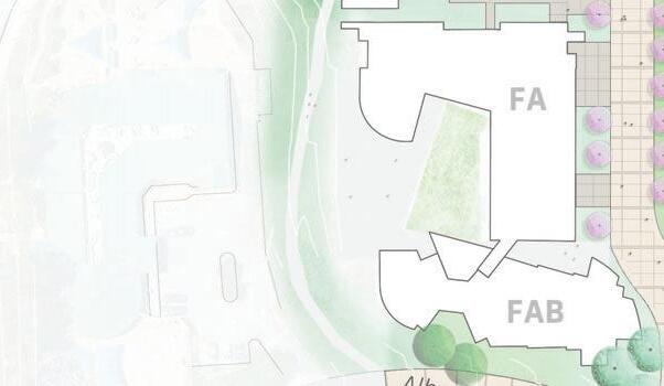
• Integrate ground level programs to enhance indoor-outdoor connectivity and extend interior programs to the exterior like at new Heldman Center and FA-B.
• See Landscape narrative for further information
• All site improvements to integrate seamlessly with Campus Accessibility Framework to create a fully accessible campus environment for students, staff and visitors of all abilities.
• Building layout and ground levels entries should provide inherent wayfinding
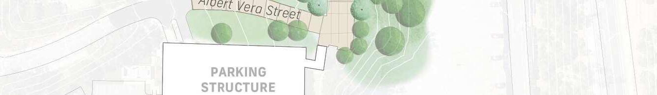
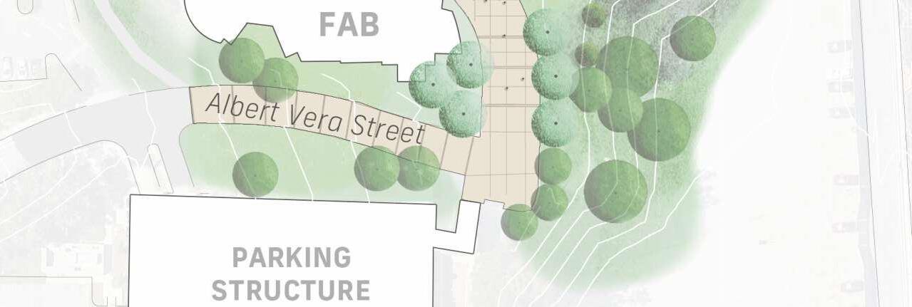
New Campus Gateway
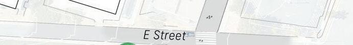
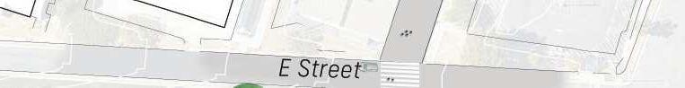
• Gateway to campus core at E Street – similar gateways at South Parking Structure and Lower Campus Quad at B Street
• Welcome arriving students and faculty from north parking areas and other modes of transportation.
• Provide lay-by lanes for public transportation and vehicle pick-up/drop-off including ride-share services.
• Gateway shall create a sense of arrival, identity and frame the campus entry.
• Provide wayfinding to orient visitors
• Provide shaded seating for waiting transportation passengers.
• Provide safe and accessible pedestrian crossings of E-Street connecting the NorthSouth Wildcat Walk with the adjacent parking and adjacent Watson Center.
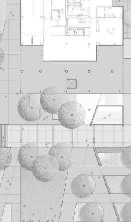
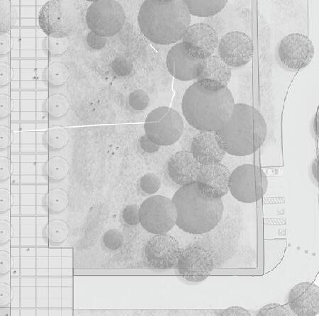
New Campus Spaces
Vista Quad (Sequence 3 - Reference Only)
• A new flexible campus open space
• replaces the former HLRC and supports large scale campus events and celebrations as well as everyday informal uses.
• The new quad shall maximize panoramic views of the LA Basin.
• Infrastructure shall be provided to support AV equipment required for performances and gatherings in multiple configurations.
• Architecturally screen the full width of the FA-B north facade, Level 1 to conceal the array of building services. Integrate concealed cart parking for facilities personnel.
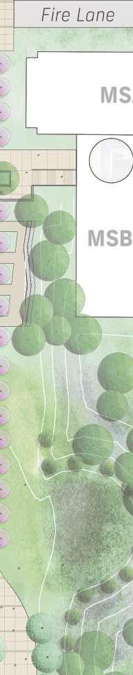
Library Terrace
• Updates the existing terrace garden to create exterior study spaces for the Learning Center programs.
• Optimize panoramic views of LA Basin.
• Provide shaded seating to accommodate a range of scales from individuals to small groups.
• Incorporate existing sculpture into design.
3.3 PROJECT SITE INTRODUCTION
Undeveloped Areas
• Plant undeveloped site areas at former bungalow sites and hillside above with native and drought tolerant plant material. Integrate native plant materials where appropriate to draw connection with adjacent Baldwin Hills hillside above.
Miscellaneous
• Heldman Center Service Area
• Screen service area equipment and cart parking from view of major pedestrian walkways.
• Screen design to integrate harmoniously with the design of Heldman Center and use the same materials and detailing.
• Use drought tolerance landscape materials throughout design – see Landscape Architecture narrative.
The overall project’s construction limits describe a site of2.7 Acres or117,930Square Feet, with a diversity of conditions and requirements, that can be considered in several parts:
• The proposed site of the HLRC Replacement, the new Heldman Center, is the current location of the Career Education Buildings A and B.
• To the north is the site of existing Bungalows to be demolished.
• New Vista Quad at the current HLRC location. Site topography and existing infrastructure present challenges to be resolved in creating what will be the largest, most usable open space on campus.
Limit of Work
Establish Drought Tolerant Landscape for Undeveloped Areas
Renew & Strengthen North-South Wildcat Walk as Shaded Campus Connection
Exterior Site Alterations Fine Arts B Entrances
Micro-forest
Project Components Diagram
NEW DR. MORRIS J. HELDMAN CENTER
Create New Dr. Morris J. Heldman Center
Create Library Terrace Garden
Recon gure & Strengthen East-West Terrace Stairs
Demolish HLRC and Create New Vista Quad
Create North Gateway to Academic Core
Create Outdoor Instruction Area
3.3 PROJECT SITE INTRODUCTION
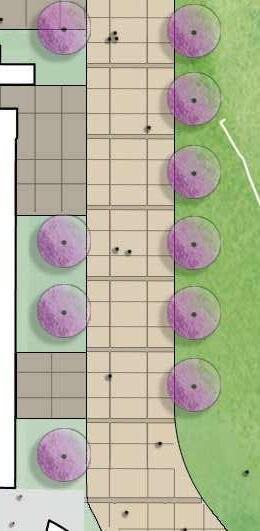
• The North-South Wildcat Walk, as a specific site component presents the opportunity for increased ‘greening’ for shade and outdoor use, site hydrology, as well as shaded outdoor seating in connection with the new Heldman Center and the new entrances to student services on the east side of Fine Arts Building B.
• The improvements to the stairway connection to the mid-level SSB-GCB courtyard.
• A new North Gateway to campus at the end of the North-South Wildcat Walk.
• Minor exterior/site alterations at entrances to the Fine Arts Building B
Site improvements that fall into the list of potential Alternatives and Enhancements are provided in Section 6.
Heldman Site Following are comments specifically related to the portions of the site affected by the demolition of the HLRC and Career Education Buildings A and B, the construction of the new Heldman Center, and creation of the new Vista Quad at the HLRC site, collectively referred to below as the Heldman Site.
Survey Information Recent surveys and evaluations of soils, topography, sustainability, and utilities are listed in 3.6 Reference Documents. Among other points, some considerations include:
• Existing Buildings and Site Structures: The New Heldman Center Site is substantially occupied by the existing HLRC and CE-A and CE-B Buildings, as well as paving, stairs, retaining walls, concrete walks and benches, a pedestrian bridge, and other structures. The pedestrian bridge would ideally be removed to improve the visual connection up and down the east-west hill climb, and is included as an alternative in Section 6.
• Site Topography: The westerly edge of the New Heldman Center Site presents complex grade changes intertwined with existing retaining walls and paths. A continuous treatment along this important interface of two campus terraces should consider accessibility, visibility, and wayfinding, especially at the crossing of the East-West hill climb up from B Street. A significant grade change of over one story descends from the western edge of the proposed New Heldman Center location.
• Geotechnical Considerations: Moist, expansive clay soils and the potential for differential settlement led the geotechnical team to recommend, among other things, overexcavation and a thick mat foundation for new construction. Planters and irrigation near buildings are recommended to be contained.
• Site Utilities: Utilities are concentrated at the north edge of the new Heldman location, and on all sides of the existing HLRC building. Storm drains run through the middle and along the south edge of the proposed new Heldman location.
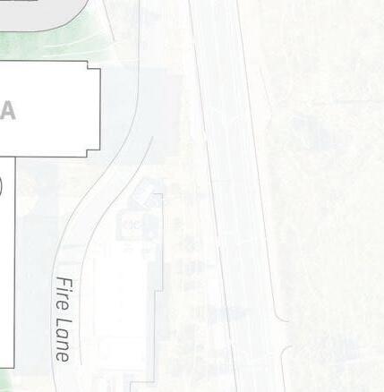
• Emergency and Service Vehicle Access: The paved central path of the North-South Wildcat Walk must maintain adequate width for fire truck access and daily service on the east and north sides of the new Heldman Center. A service courtyard planned on the north side and frontdoor service to the PAWS shop on the east.
Elevation and Views Placement on the upper terrace of the campus means the New Heldman Center has an opportunity to capture much of the view enjoyed by the existing HLRC.
Solar Orientation The overall orientation of the campus, the topography, and adjacent buildings tends to drive the massing of the new Heldman Center into a longer north-south volume. Consequently, long east and west elevations of the building present familiar design challenges- to mitigate solar gain in the cooling season, and to control daylight for interior functions.
3.4 PROJECT SCOPE OUTLINE
WLAC and the District intend to employ the DesignBuild method to deliver the project. This document has been prepared to describe the general scope of the project and set forth program and design criteria, and to allow and encourage creative design solutions to meet those requirements within allowable project funding and other constraints. The following components of the overall project scope are further described under sections 4 Program and 5 Design Criteria, as well as 3.4 Code Requirements and 3.5 Reference Documents. The Design Build Entity (DBE) shall interpret all such descriptions of scope, requirements, and criteria as minimum standards for the quantity, quality, and/ or performance of all project components and the project as a whole.
A BUILDING AND CAMPUS MODERNIZATION PROGRAM
The Dr. Morris J. Heldman Center Project is a transformational opportunity for the West LA College to re-imagine and renew the academic core of the campus and create a vibrant center for learning, personal growth and social engagement. The expansive project scope encompasses the entirety of the North-South Wildcat Walk and associated buildings and enhances connectivity between the campus terraces. Several sub-projects and/or phases comprise the larger project and fall into six overall categories of work:
1. Project Design and Documentation Process
The design of the New Heldman Center calls for a process of engagement with District leadership and project management, campus leadership and WLAC Building User Groups. The Design Build Entity shall outline in detail an inclusive, interactive design process as part of its proposal.
2. The New Heldman Center This new 69,230 GSF facility replaces and updates the Library and Learning Center programs of the existing HLRC and introduces a Student Union program – a student serving resource that includes ASO programs and is new to the West LA campus. This lively student focused facility also provides a range of faculty and staff support and development programs and recreates the large multi-function Assembly Rooms located on the top floor of the DMJHC with enhanced flexibility and capacity.
3. Public Realm Improvements and Renewal
The removal of aging facilities and the creation of the new Heldman Center will be complimented with extensive redevelopment of the North-South Wildcat Walk and East-West Terrace Stairs to strengthen these important campus connectors and to improve the quality, access and experience of campus users. The project also includes the creation of new campus gathering spaces – Terrace Quad and the Library Garden Terrace. These new flexible spaces will support day-to-day student life and learning as well as large campus gatherings and celebrations to create a unique sense of place and identity for the campus community.
Integrating interior programs with adjoining campus spaces is an essential design criterion for the new Heldman Center so that programs can be extended to the exterior and create outdoor teaching and learning spaces and provide places for social engagement. The new building shall be designed to animate exterior spaces through transparency and by strategically locating student serving programs around the ground level.
4. Infrastructure Relocation and Improvements
Reference is made to the “West Los Angeles College Energy Efficiency/ Utility Infrastructure Survey” (Cardno, 04/17/2020) and the “Campus Improvements Utility Infrastructure” (Various Consultants, 2004). Removal, replacement, and/or relocation of existing and provision of new site utilities shall meet the requirements of the PPC and the project generally, and support WLAC’s goals for site sustainability and operational efficiency. Systems affected by the project include but are not limited to: • Surface, roof, foundation, and storm drainage
Sanitary sewer
Potable water
Hot Water
Chilled Water
Fire Suppression Water
Electrical Service
Telecom and Data • Site lighting and emergency systems • Photovoltaic panels (PV’s)
3.5 CODES AND REGULATIONS
All work on the DMJHC shall be performed according to the latest current building codes, ordinances, and laws stipulated by the Authority Having Jurisdiction, (AHJ) on the project. Design and construction codes and standards are listed below. The codes and standards listed shall be the minimum requirements of the project. Codes and Standards shall be thoroughly examined for applicability to the project. Nothing shall prevent the DBE team from exceeding the applicable requirements. In most cases, the most recent editions of codes and referenced standards apply. The DBE is ultimately responsible for verifying and conforming to the current applicable codes and standards adopted by the District and the Division of the State Architect (DSA).
Examples of applicable Codes include but are not limited to:
• California Building Code
• California Mechanical Code
• California Plumbing Code
• California Electrical Code
• California Energy Code
• California Fire Code
• California Building Code/California Fire Code
• California Building Code
• California Energy Code
• California Green Building Code
• Elevator Safety Orders
References and Guidelines
• LEED v4.1 US Green Building Council
• National Fire Protection Association, NFPA 110: Life Safety Code
• Americans with Disabilities Act (ADA, Federal). Compare with the State of California codes and use the most stringent.
• Seismic Safety Standards for Library Shelving: Manual of Recommended Practice by Gary Strong & John Shelton and sponsored by Office of State Architect and California State Library Foundation
DBE is responsible for coordinating with the State and local Fire Marshals on all fire suppression matters. This project falls within the Very High Fire Hazard Zone per CalFire maps and must follow CBC Chapter 7a as applicable.
3.6 REFERENCE DOCUMENTS
LACCD and West Los Angeles College have provided documents, that include project information and/or requirements. The DBE shall fully review, be familiar with, and reference all pertinent information, requirements, standards, restrictions, and constraints contained therein. The DBE shall notify the District of additional information it deems necessary to fulfill project requirements, and/or requiring clarification.
1. Program
• “Space Utilization Analysis and Preprogramming Report, WLAC HLRC Replacement Project” STIR Architecture, April 26, 2019
• “HLRC & Repurposing Project Space Verification”, ALMA 2019 or as updated
2. District Standards
BuildLACCD Standards and Guidelines with Addenda are found at: https://www.build-laccd.org/resources/designstandards/
• Design Guidelines and Standards
• District Specifications
• Guideline Specification Sections per CSI MasterFormat
• Campus Specifications Matrix
• List of preferred manufactured materials and systems for each of the 9 campuses.
DBE shall note there are references to other District documents within the Guidelines and Standards that are subject to change and more detail like Sustainability.
Additional Reference Documents
• FF&E Scope of Services
• FF&E Specifications
• Technology Responsibility Matrix
• WLAC Exterior Campus Signage Plan
3. Campus Standards and Project Information
Construction & As-Built Documents
• WLAC Campus Electrical Single Line
• WLAC Campus Piping Irrigation & Asbestos
Project Information and Reports
• WLAC DJMHC Project Schedule
• WLAC DJMHC Owner Project Requirements
• WLAC Topographic Survey for WLAC by IDS Group, July 27, 2020
• WLAC Campus Specifications Matrix and Addenda to the Standards are found at: http://www.build-laccd.org/contractorsbidders/standards-guidelines/quick-searchresults?type=guidelines&category=10
• WLAC Energy Efficiency / Utility Infrastructure Survey by CARDNO, April 17, 2020 - Updated July 20, 2023
• HLRC Building Geotechnical Report by Koury Engineering & Testing, Inc., July 2, 2020Updated May 11, 2023 and California Geological Survey Approval dated September 7, 2023
• MDF2 Secondary Telecom Standards
• WLAC Climatech Per Bldg Metering Summary
• WLAC STIR Pre-Programming Report w/ Appendix, April 30, 2019
3.7 DEFINITIONS AND ABBREVIATIONS
The following definitions will assist in the use of this Project Program and Criteria document:
Gross Square Feet - the total floor area of a building including all levels, that are totally enclosed within the building envelope
Assignable Square Feet - the usable area required to accommodate a function, equipment, an occupant, or an occupant group. The assigned square footage of space (equal to capacity times ASF/unit); typically described as “wall-to-wall” or “usable area”
Audio Visual
Design Build Entity (DBE), same as “Design Builder”
Vertical circulation, restrooms, and building service
Not applicable
College Project Team
District Project Manager
Design Team: A typical design team may consist of a design-build entity, design architect, civil/structural/ mechanical engineers, landscape architect, audio/visual consultant, acoustic consultant, security consultant and/or other specialties that may be required depending on the project are IT or technology consultant, and lighting consultant.
Path of Travel
PROVIDER / INSTALLER
OFDBI OFOI
DBFDBI
Owner-Furnished and Design-Build Entity Installed
Owner-Furnished and Owner Installed
Design-Build Entity Furnished and Design-Build Entity Installed
OFCI
CFCI
Owner Furnished - Contractor Installed
Contractor Furnished - Contractor Installed
NATURAL LIGHTING TERMINOLOGY
Required
Natural lighting must be provided
Preferred
Provide natural lighting when possible
STC
Sound Transmission Coefficient- a measure of sound attenuation between spaces
3.8 PATH OF TRAVEL
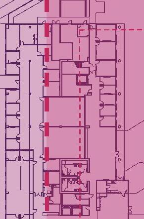
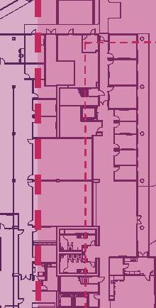
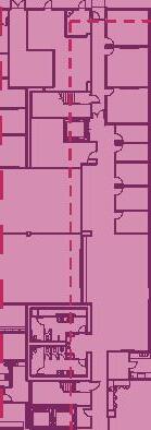
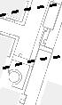
This diagram describes the intent for fencing alignment and the Path of Travel (POT) around the site during construction of DMJHC in Sequence 2. The DBE shall propose actual alignments of fencing and pathways for review with the District.
CONST. TRAILERS
CONSTRUCTION MATERIALS STAGING AREA
- ESTABLISH IN SEQ 1
- ESTABLISH IN SEQ 2
Note: In the event that there is a discrepancy between the Program information contained in the PPC and the Bridging Documents, the PPC shall take precedent and prevail. The Design Build Entity (DBE) shall notify the College Project Team (CPT) and/or District Project Manager (DPM) of any discrepancies in writing.
The Dr. Morris J. Heldman Center (DMJHC) project relocates 29 stakeholder departments. The new work spaces will be accommodated by four separate projects; a combination of new construction and re-purposing in three existing campus facilities as follows:
• Dr. Morris J. Heldman Center – New Construction
• Math & Science, Building A – Re-purposing
• Student Services Building – Re-purposing
• Fine Arts, Building B – Re-purposing
The program summary has been organized accordingly showing the distribution of department programs across the four scopes. Individual department space lists have been similarly grouped by project building.
Program areas are listed as assignable square feet (ASF) on the individual program space lists. The Program Summary provides ASF and Gross Square Foot (GSF) areas. Efficiency factors reflecting either new or re-purposing construction have been applied to the ASF areas to create the GSF area. The efficiency factor for new construction reflects industry standards for the building typology while the efficiency of the re-purposing projects is an estimate.
Building Support Spaces: Building support area is among the largest contributors to non-assignable building area which determines a program’s efficiency factor. Building support spaces include mechanical, electrical, plumbing, AV/telecommunications closets,
Campus Stakeholder Relocation Strategy Diagram
SPACE PROGRAM SUMMARY
custodial spaces, trash rooms, restrooms, gender inclusive restrooms and Lactation Rooms. These spaces are not calculated as part of the building’s assignable square footage but are specifically called out because of their importance. It must be noted that not all Building Support spaces are being identified and it is expected that the DBE shall address the individual needs of the project for code compliance, functionality and conformity with BuildLACCD and WLAC standards.
Introduction: The Space Program and associated information shall be viewed as the minimum requirements. It is anticipated that the Design Build Entity (DBE) shall provide their interpretation of the program information including value added approaches. The programming documents and diagrams are provided as reference concepts to illustrate preferred adjacencies and shall not be construed as completed designs. The programmatic drawings provided as reference concepts to illustrate preferred adjacencies and should not be construed as completed designs.
The ASF has been provided for each required space; GSF is to be determined by the Design Build Entity and shall include but not be limited to: building structure; building circulation; support spaces such as mechanical, electrical, telecommunications; general toilet rooms; maintenance spaces.
Terminology: In compiling a space program, a number of terms are used to identify the appropriate area for the building. The subsequent sheets use the following terminology to generate the building’s space needs.
Occupants (Occ): The number of expected occupants / seats per room
Quantity (Qty):The number of rooms
Assignable Square Feet (ASF): The usable area required to accommodate a function, equipment, an occupant, or an occupant group.The assigned square footage of space (equal to capacity times ASF/unit); typically described as “wall-to-wall” or “usable area”. ASF excludes wall thickness, structure, circulation spaces and building support spaces.
Gross Square Feet (GSF): Total area of the building
4.1.1 Site Design of Public Realm
Function: The design and renewal of the WLAC exterior open space network for the Academic Core will unify the campus environment and capitalize on the unique opportunities its location to create a unique identity for the college and a source of pride for the college community and alumni. The campus’ public realm creates a cohesive whole but is comprised of several discrete elementseach playing a specific role in the choreography of pedestrian movement, service/emergency access, social interaction and campus gatherings.
North-South Wildcat Walk
Integrated rain-garden
East-West Terrace Walk & Stairs
Vista Quad
Garden Terrace & Library Terrace
Terrace stairs and ramp – Additive Alternate Campus Gateways
North Gate
Service Yards
Heldman Center
Fine Arts, Building B
Reclaimed areas – hillside and former building sites
Criteria:
Safe pedestrian environment - 24/7
Comfortable shaded exterior space with ample seating
Climate adapted / low irrigation sustainable landscape - low maintenance and low water usage
Comprehensive storm-water strategy (raingarden) integrating landscape design with campus storm-water system - promotes efficient water use creates shaded pedestrian environment
Integrate interior and exterior programs
Exterior WiFi access and access to power outlets for charging equipment
4.2 DR. MORRIS J. HELDMAN CENTER
Building Program Overview
The New Heldman Center program integrates the library, learning center and student union programs to create a vibrant new hub for learning and social interaction that supports the whole student in their pursuit of student success.
Planning
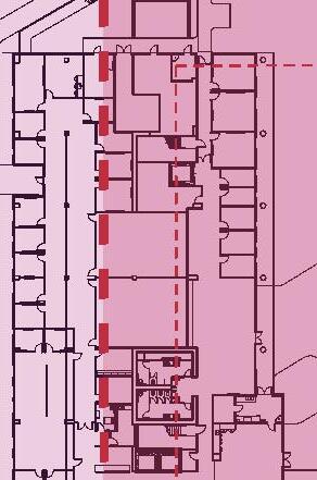
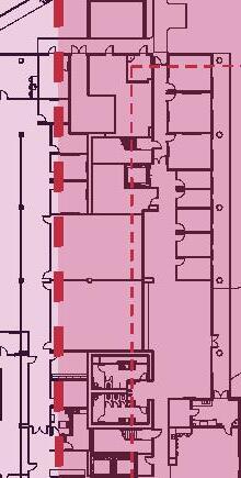
The organizational blocking and stacking of building programs optimizes internal functional relationships, activates the surrounding campus spaces while orienting programs toward campus views and daylighting. Programs are strategically stacked, locating the most active and noisy uses at the lowest levels with quieter programs occupying the upper levels to support focused study. A glassy multistory entrance lobby creates a bold identity for the new building located at the important campus intersection of the North-South Wildcat Walk and Terrace Stairs while supporting internal way-finding. Ground level programs shall strongly engage the surrounding campus spaces to extend programs to the exterior where possible and activate the campus spaces. The Event Center and other faculty serving programs occupy the top level with panoramic views of the Baldwin Hills and across the LA Basin. The Event Center is a multi-purpose gathering space supporting large gatherings, symposiums and campus celebrations that replaces a similar facility on top of the existing HLRC.
For the New Heldman Center programs, additional programming information is provided in Section 4.2.11 – New Heldman Center Space Summary with Equipment & Furnishings.
Included Programs:
Adult & Continuing Education
Career Connections Center
College & Career Prep
Learning Center / Math & Writing Labs
Library
o Circulation Services
o New Acquisitions & Display
o Periodicals
o Reference Service / Group Study
o Collection Stacks & Reader Stations
o Teaching Classroom
o Library Tech Services
o Distance Learning
o Faculty and Staff Development
Multi-Media Services
PAWS
Student Union / ASO
Teaching and Learning
Event Center
Heldman Center, Level 1
Heldman Center, Level 2
Heldman Center, Level 3
Heldman Center, Level 4
4.2.1 ADULT CONTINUING EDUCATION
Function: Supports very diverse groups of learners including: middle/high school students, life-long learners, returning professionals, vocational certifications, under-served, vulnerable adult populations such as non-high school graduates, English language learners, disabled, underemployed, and re-entry (formerly incarcerated) students.
Criteria
Location adjacent to lobby and elevators for visitors but does not require a public face. Shares conference room and kitchenette with Library Tech Services
Note: For the Heldman center programs, additional programming information is provided in Section 4.2.11 - Heldman Space Summary with Equipment & Furnishings
4.2.2 CAREER CONNECTION
Function:
Career Connections offers a diverse range of programs, services and resources that support and facilitate career exploration, job readiness programs and employment placement for students. http://www.wlac.edu/Career-Center/index.aspx
Criteria
Program to be integrated into the Learning Center (LC)
Shall have its own identity and entrance pathway enabling students to bypass the LC check-in kiosk.
Notes:
1. Hours of Operation: 8-5 M-F
2. Wayfinding is important
3. Near parking
4. Workshops are conducted and held in the Learning Center (income stream)
5. For the Heldman center programs, additional programming information is provided in Section 4.2.11 - Heldman Space Summary with Equipment & Furnishings
4.2.3 COLLEGE AND CAREER PREP
Function:
The CCP Division supports new and returning students by offering counseling and non-credit courses designed to help students successfully enter or re-enter the workforce or advance on the job. http://www.wlac.edu/free-college/index.aspx
Criteria
Integrated with the Learning Center programs
Note: For the Heldman center programs, additional programming information is provided in Section 4.2.11 - Heldman Space Summary with Equipment & Furnishings
4.2.4 LEARNING CENTER / MATH & WRITING LABS
Function: A major instructional support center for the campus that integrates several programs including Math & Writing Labs, College & Career Prep and Career Connections. The Learning Center supports the diverse student population with the tools needed for academic success and serves as a hub for instructor-student interaction, learning both inside and outside the classroom, instructional support in a lab setting, and peer learning through tutoring and study groups. The availability of computers and extended hours enable support computer literacy and application needs.
Organization: A layered organization places open tutorial space and Group Study Room close to the exterior for natural daylighting and access to the Garden Terrace while the Math & Writing Labs are located inboard to optimize light control for presentations and reduced glare on computer screens.
Criteria
Strong building Lobby presence – clear wayfinding
Flexibly designed Math & Writing Labs to accommodate a range of curricula. Provide check-in kiosk at Learning Center entrance for arriving students
Note: For the Heldman center programs, additional programming information is provided in Section 4.2.11 - Heldman Space Summary with Equipment & Furnishings
4.2.5 LIBRARY
Function: The new library provides a state of the art learning environment for students and faculty with access to a wide range of information media and knowledge creation tools in a highly interactive environment that encourages collaboration and student success. The program specifies a range of study environments for users to select from for their specific study needs or learning styles. The design of the library space shall emphasize openness and transparency to support ease of way-finding, user security and oversight by library staff.
Organization: The library occupies 2 levels of the new Heldman Center with its entry located on Level 2 overlooking the multi-story entry lobby and access by way of the grand architectural stairs or the elevators. The Circulation and Reference Desks serve as the library gateway on Level 2 and provide oversight for the Information Commons, Classroom, Periodicals and Library Computers which have access to exterior reader/study space on the terrace with panoramic views. Level 3 houses the catalog stacks, reader space and Library Tech Services which provide oversight for this level. Library Computers and Group Study Rooms are located throughout the library levels for distributed access to technology and a variety of study/ collaboration environments.
Collection: The Libraries collections stored on site are designed to support an undergraduate curriculum and includes; a general book collection, a browsing collection of periodicals and a collection of various instructional media formats. In addition there is a well-used reserve textbook collection, numerous anatomical models and other specialized reserve materials for student use.
Book Collection - 75,249 total volumes that breaks down in the following manner:
Circulating Collection - 66,449 volumes
(including new book display)
Reference Collection - 8,000 volumes
Reserve Textbooks - 800 volumes
Periodicals - 360 (includes magazines and newspapers on display and bound back issues)
Display titles = 60
Bound volumes = 300
Multimedia - 5,925
Compact Discs - 980
DVD - 176
Video Cassettes - 4769
Criteria
Provide sight-lines for oversight of all library spaces
Provide transparent partitions at all Group Study Rooms for oversight and security
Provide low-glare naturally day-lit work spaces and natural ventilation where possible for a healthful and effective learning environment
Provide reader seating on both levels of multi-story lobby mezzanine
Integrate interior and exterior stairs at Lobby where possible.
Provide robust security strategy and system to protect library collection including deterrence at emergency exits
Provide (3) book drop locations throughout the Heldman building:
Accessible to building exterior
Accessible to the interior building atrium
Located at the library circulation desk
Library Collection and Display Shelving Design Criteria
Collection shelving is a critical design opportunity that plays an essential role in the function and architectural expression of the library environment, supporting collection storage, management and display, wayfinding, shaping reader spaces and creating a cohesive architectural expression. The DBE shall work closely with library users to incorporate the following requirements and refine the design and configuration of the collection and display shelving the meeting the needs and goals the program.
Free standing catalog shelving or display shelving shall be of a “cantilever design”, rigidly affixed to the building structure per manufacturer and building code requirements to resist seismic events when fully loaded. The DBE is responsible for anchorage design. For seismic design of shelving, refer to “Seismic safety standards for library Shelving: manual of recommended practice” by Gary Strong
& John Shelton and sponsored by Office of State Architect and California State Library Foundation. All shelving to be fully designed and inspected during fabrication to meet ASCE 7-16 Section 15.5 (NonBuilding Structure) & ANSI/RMI MH16.1. Wall mounted catalog shelving or display shelving shall be similarly rigidly affixed to the building structure per manufacturer and building code requirements to resist seismic events. The DBE is responsible for anchorage design.
The configuration of shelving systems and the layout of aisles shall be fully accessible – 42” aisle widths recommended. Shelving materials and finish shall be complementary to the architectural design of the building. Black is the preferred color for the shelves themselves.
Catalog range end panels at the end of each aisle shall be considered a special design element that enhance library function, wayfinding and integrate the collection shelving into the building design. The DBE shall determine the specific requirements, functionality and design during the programming and design phases with the library users including use of aesthetically complementary materials, featured book display, electronic display and integrated lighting. All power and data services and structural bracing/support shall be concealed.
Shelving depths will vary with the requirements of the collection and materials and shall be confirmed with library users to optimize flexibility and functionality.
Collection stack lighting shall be integrated into the shelving units for flexibility of stack layout, ease of maintenance/aiming and to provide even lighting of the collection (book spines and other materials) on all shelves with a minimum level of illumination of 15 foot-candles (vertical surface) at the bottom shelf.
Library and Learning Center Lighting Design Criteria
The lighting design will play a key role in creating visually rich, easily navigable, accessible and effective learning environments. High quality lighting design integrating ample daylighting and views has
been proven to enhance student outcomes and promotes staff satisfaction. The building design shall maximize the use of natural daylighting and daylight harvesting to provide well lit and energy efficient learning spaces that are free of glare and direct sunlight. DBE shall work closely with the Library and Learning Center stakeholders to develop lighting design solutions that fully support the requirements of the Library and Learning Center programs.
An automatically dimmable LED lighting system using photocells shall provide a consistent level of lighting throughout the Library and Learning Center program areas during hours of operation - day and night. The Electrical design narrative provides minimum lighting levels to be achieved by program space type for vertical and horizontal surfaces. Horizontal lighting levels measured at 30” above the floor. Task lighting shall be provided at work or study areas requiring higher levels of lighting. Recommended use of direct/indirect lighting fixtures for general lighting throughout to illuminate building volumes and expand the perception of the spaces while minimizing shadow and contrast. Occupancy sensors are required for offices and highly recommended for smaller intermittently used spaces to support energy efficiency.
Collection and Study Spaces
Collection Stacks – Shelving units with integrated light fixtures as described in preceding Shelving Design Criteria. Recommended use of motion sensors in stack aisles to dim lighting when not needed while maintaining required egress lighting levels.
Carrels with dividers – Provide undershelf task lighting
Study Rooms – Provide individual control of dimmable lighting for video presentation on flat panel display
Classrooms – Zoned dimmable lighting for note-taking during video presentations or reconfiguring for alternative furniture layouts.
Specialty Lighting
Artwork and Display – Provide adjustable and dimmable lighting strategies that can be reconfigured to accommodate changing exhibition requirements.
Public Service areas – Provide appropriate lighting to create visual hierarchy and support wayfinding, signage and transactional activities.
Media Production – Adjustable lighting solutions for creating media content / videos.
Library Tech Services
Function: Office suite and work spaces for the library administration to provide oversight and direction of library functions, maintain the variety of collections and data bases. Located on Level 3, the Tech Services provides continuous oversight of adjacent library functions.
Criteria
Low glare naturally day-lit work spaces for high quality work environment.
Internal suite circulation configured to allow movement of library materials (includes passing book trucks).
Visual connectivity between suite and library programs for oversight.
Distance Learning
Function: Supports students enrolled in the College’s online, hybrid and web-enhanced classes. Creates the online pedagogical environment to maximize opportunities for student success through technical support for both students and faculty and through collaboration with Student Services staff to facilitate access to, and utilization of, online student support services. Responsibilities also include training faculty on new applications in the Faculty Development program.
Faculty and Staff Development
Function: A new program for the College supporting the faculty and staff communities with professional and organizational development. Strong relationship with Distance Learning and Teaching & Learning for skills and technology training. Facilitates cross pollination between faculty of other institutions.
Criteria
Flexibly configure Main Room to accommodate a range of activities
Provide direct access to roof terrace for outside gatherings / events.
/ 8 * +' 7 7 ) 7/ /
8 * +' 7 7 ) 7/ /
8 * +' 7 7 ) 7/ / 3!7 77 (. '!
Note: For the Heldman center programs, additional programming information is provided in Section 4.2.11 - Heldman Space Summary with Equipment & Furnishings
4.2.6 MULTI-MEDIA
Function: Supports campus-wide access to audiovisual technology and media including teaching technologies for classrooms, the library, student life programs, campus gatherings and public events. Collaborates closely with Teaching & Learning program for resource sharing and technology support.
Criteria
Robust and accessible AV infrastructure design to accommodate future needs and system maintenance and upgrades.
Note: For the Heldman center programs, additional programming information is provided in Section 4.2.11 - Heldman Space Summary with Equipment & Furnishings
4.2.7 PAWS / CATERING
Function: PAWS, a campus operated convenience store, providing the campus community with quick grab n’ go food options and limited school supplies and sundries. PAWS stocks a variety of prepared snacks and drinks providing a unique food option on Campus that is open after hours and weekends. With access from the exterior and the main lobby, PAWS will serve patrons independent of the building’s operating hours. PAWS will play a key role in the revitalization of the North-South Wildcat Walk with outdoor access and seating to create a new area of gathering and community.
DBE to verify and integrate requirements of LA County Health Department.
Criteria
Locate at the heart of student movement and along the NW Quad.
Ground floor location will activate exterior spaces.
Provide exterior and interior entries to create a building and campus amenity. Transparency, color and graphics support branding and wayfinding.
Develop outdoor seating area into landscape design.
Provide separate service access with nearby access to custodial room and service elevator.
Develop delivery and waste management strategy integrated with campus operations and safety.
Notes:
1. Trash/Recycling will be managed through Campus Operations, removing refuse throughout the day.
2. Provide separate service access with nearby access to service elevator,
3. Security: provide (1) camera in Staff workroom, (3) cameras at selling floor
4. For the Heldman Center programs, additional programming information is provided in Section 4.2.11 - Heldman Space Summary with Equipment & Furnishings
4.2.8 STUDENT UNION / ASO
Function: Seen as the “Living Room” of the college, the Student Union provides a variety of flexible gathering and meeting spaces to support the full range of student life activities and programs including informal gathering spaces, student clubs and student government offices.
Organization: Prominently located in the multistory building lobby space and the discreet Student Lounge, the planning provides students choice about their social environment. By placing students at the forefront, the Heldman Center creates a place for students and makes student success its priority.
Criteria
A welcoming comfortable place for students to hang out.
Open, transparent to see and be seen by fellow students.
Present resources through clear wayfinding Flexible planning and furnishings accommodating a wide range of activities and performance - easy reconfigured Planning integrated with adjoining exterior campus spaces.
Strong connection to PAWS requested Acoustic treatment essential to create comfortable but active environment. Opportunity for exhibition featuring student work or current events.
Note:
Heldman
4.2.9 TEACHING AND LEARNING
Function: The Office of Teaching & Learning supports faculty to improve student learning and provides leadership for campus-wide outcomes assessment processes; supporting strategies for student success; developing and directing professional learning programs; researching and implementing new tools, technology, and resources for instruction; engaging in grant development and management that meets college goals while matching requirements of funding agencies; and supporting the ACT Program. Collaborates with Multi-Media program for resource sharing and technology support.
Criteria
High acoustic performance at production spaces for high-quality content creation.
TEACHING & LEARNING
Faculty Development
Office / Conference
O-20Dean's Office11150150
O-10Coordinator Office21120120 270
Shared Spaces
S-41Digital Design Control Room1110110
S-40Digital Design AV Recording3130390
S-44Open Office / Work Space1260260Shared with Multi-Media Services
S-43Digital Studio Space1100100Shared with Multi-Media Services 860
SUBTOTAL 1,130 ASF Total
Shared Programs:
NADigital Production Suite03500Shared with Multi-Media Services
NAStorage & Supplies01900Shared with Multi-Media Services
Note: For the Heldman center programs, additional programming information is provided in Section 4.2.11 - Heldman Space Summary with Equipment & Furnishings
4.2.10 EVENT CENTER
Function: Flexible multi-purpose space for campus and District events, symposiums and celebrations with potential for rental to off-campus entities. It shall be designed to accommodate a large single event or multiple simultaneous events with acoustic room dividing partitions.
Organization:
Located on the top floor, the Events Center shall provide spectacular panoramic views of the LA Basin from Hollywood Hills to Marina del Rey and the ocean beyond. A gallery space along the west side serves as event pre-function, exhibit or performance space and potential library reader space when not needed for events. Large sliding windows open for balcony-like feel during good weather and closed during windy or inclement periods. DBE to ensure protection of large openings. A corridor accessing faculty serving programs runs along the east side of the Event Center and serves as “back-of-house service access” to Catering Prep and Equipment Storage during events.
EVENT CENTER
Criteria
Maximize openness of west gallery window system for a truly covered balcony feel. Flexible planning and design of Events Spaces to optimize ranges of events and uses.
Ensure acoustic isolation during simultaneous events.
Flexible AV design and straight forward control design for user friendliness. Develop an active shooter egress route strategy with and approved by LACCD.
Prefunction & Open Terrace
Specialty
S-11Assembly Room38402,520
S-11Assembly Storage1245245
S-10Catering Kitchen1276276
Adjacent spaces to be used individually or combined for larger events using retractable acoustic partitions.
Accessed from outside space so not to disturb events
Adjacent to service elevator. Provide discreet access to Assembly Room(s) in all configurations to minimize disruption to events.
SUBTOTAL 3,041 ASF Total
Note: For the Heldman center programs, additional programming information is provided in Section 4.2.11 - Heldman Space Summary with Equipment & Furnishings
4.2.11 HELDMAN CENTER SPACE SUMMARY WITH EQUIPMENT & FURNISHINGS 4.2 DR. MORRIS J. HELDMAN CENTER
Library Division Space NameFurniture & EquipmentQtyUnitSqFtTotal
Space NameFurniture & EquipmentQtyUnitSqFtTotal DEANS OFFICE (T & L) Calculator100
Chair, Task100
Chair, Guest100
Computer, Staff Desktop 2100
File Cabinet, Vertical (Four Drawer)188 Lamp100
Printer, Laser (B&W)100
Shelving, SF 60”h Wood W/ 4 Shelves11010
Telephone Handset100
Waste Basket122
White Board100
Workstation, Department Head's Office System1120120
DIGITAL DESIGN - AV CONTROL ROOM
Avid Pro Tools100
Chair, Task248 Mac Pro100
Queuing Space (Per Person)6636
Studio Monitors (Genelec 7050B)100
Telephone Handset100
Waste Basket111
Workstation, Studio Console (L-Shaped)16565
DIGITAL DESIGN - AV RECORDING #1
Boom Mic, Pole Cables155
Chair, Task200
Mic Preamp (Neve 1073 DPA)100
Mic Stands & Booms11010
Microphone, Push-to-talk W Speaker155
Studio Acoustic Drapes100
Table, Work1110110
Waste Basket100
DIGITAL DESIGN - AV RECORDING #2
Boom Mic, Pole Cables155
Chair, Task200
Mic Preamp (Neve 1073 DPA)100
Mic Stands & Booms11010
Microphone, Push-to-talk W Speaker155
Microphones (AudioTechnica 4000 Series)100
Studio Acoustic Drapes100
Table, Work1110110
Waste Basket100
4.2 DR. MORRIS J. HELDMAN CENTER
Space NameFurniture & EquipmentQtyUnitSqFtTotal
DIGITAL DESIGN - AV RECORDING #3
Boom Mic, Pole Cables155
Chair, Task200
Mic Preamp (Neve 1073 DPA)100
Mic Stands & Booms11010
Microphone, Push-to-talk W Speaker155
Microphones (AudioTechnica 4000 Series)200
Studio Acoustic Drapes100
Table, Work1110110
Waste Basket100
DIGITAL STUDIO SPACE (SHARED W MM SERVICES)
Waste Basket100
OFFICE (SHARED)
Chair, Task200
Chair, Visitor's21530
Lamp, Desk200
Printer, Laser (color) Network133
Shelving, SF 60”h Wood W/ 4 Shelves21224
Telephone Handset200
White Board200
Workstation, Clerical Office System2100200
FACULTY INNOVATION LAB
Faculty Innovation Lab
Markerboard200
Cabinets, Above Counter600
Cabinets, Below Counter600
Preparation Counter15656
Recycle Bin3412
Waste Basket200
White Board100
Chair, Task1600
Work Table1200
Mobile Storage Cabinet1200
Mobile Whiteboard600
Computer, Staff Desktop 2400
TV Monitor 80" Flat Panel (wall Hung)200
Preparation Counter12430
Printer, Laser (Color)100
Printer, 3D200
Recycle Bin3412
Waste Basket428
43,764
4.3 ROOM DATA SHEETS
OFFICE, OPEN WORK SPACES, AND OFFICE SUITES
O-10 Office
O-11 Shared Office
O-20 Office
O-21 Shared Office
O-30 Office
O-40 Office
OW-10 Open Workstation
OW-20 Open Workstation
OS-10 Reception (0-3 Visitors)
OS-20 Reception (4 Visitors)
OS-30 Reception and Work Area
MEETING AND CONFERENCE ROOMS
C-10 Meeting Room (5 seat)
C-20 Meeting Room (8 seat)
C-30 Meeting Room (12 seat)
C-40 Meeting Room (20 seat)
C-50 Meeting Room (24 seat)
CLASSROOM / LABS
CR-10 Classroom (Large)
CR-20 Math Lab
CR-30 Writing Lab
BREAK ROOMS
BR-10 Break Area (small)
BR-20 Break Room (small)
BR-40 Break Room (Large)
BR-50 Faculty and Staff Lounge
BUILDING SUPPORT SPACES
BS-10 Storage Room
BS-20 AV Closet
BS-30 Custodial Room
SPECIALTY SPACES
S-10 Catering Kitchen
S-11 Assembly Room and Storage
S-30 Library Circulation Services
S-31 Library Reference Desk/Hub
S-32 Tech Services Workroom
S-33 Catalog Shelving & Reader Seating
S-34 Learning Center Main Room
S-35 Library Computers
S-40 Digital Design AV Recording
S-41 Digital Design Control Room
S-42 Digital Design Production Suite
S-43 Digital Design Studio Space
S-44 Open Office Work Space
S-45 Digital Design Studio Control Room
S-46 Storage & Supplies
S-50 PAWs (Back of House)
S-51 PAWs (Front of House)
S-71 Copy/Print Room
S-72 Faculty Innovation Lab
LEGEND
Electrical / Communication
floor box with quad power and data receptacles
wall mounted duplex power receptacle
wall mounted quad power receptacle
telecom & data receptacle
floor box with AV, data and power receptacles
Equipment
ceiling mounted projector - provide AV, data and power
heavy duty porcelain marker board with marker tray
ceiling mounted projection screen - motorized
- provide power & wall switch
flat panel display
- provide dedicated AV, power/data
- concealed conduit connection to AV equipment
ceiling AV speaker
wireless data access point at wall or ceiling
wall AV connection
wall video conference camera (+42” AFF or under screen)
equipment rack with power, data and AV
room scheduling panel
wall phone
card reader
desktop printer/copier
computer workstation
-provide power & data
Furnishings
Accessibility
60” dia wheelchair turning space 60”
wheelchair seating space
Door access
• Interior door
• With closer & latch
GENERAL NOTES:
• For Heldman Center programs refer to Section 4.2.11 for equipment and furnishings
• Provide power(quad) and data to all workstation locations shown with a computer screen symbol or listed in ROOM CONTENTS.
• The plan diagrams provided on the Room Data Sheets describe preferred functional relationships including approximate sizes and shall not be considered resolved design solutions to be implemented literally. The DBE is solely responsible for compliance with all the requirements of the program, WLAC and LACCD standards and governing codes and laws.
• All appliances, fixtures and accessories shall be ADA accessible and their final installation shall comply with all accessibility requirements.
• Provide concealed backing for all wall mounted furnishings and equipment.
• Refer to Appendix for FF & E responsibility.
• Room Dimensions are approximate. Refer to Chapter 4.2 for Program Areas.
wireless data access point
card reader
SAMPLE TEST FIT PLAN A
Scale: 1/8” = 1’-0”
SAMPLE TEST FIT PLAN B
Scale: 1/4” = 1’-0”
combination power, data instructor station equipment ceiling speaker
SPACE DESCRIPTION
GENERAL DESCRIPTION
Private office space for one staff, including space for computer workstation, desk, file storage, books and reference materials shelves, and comfortable flexible seating for meetings with 1-2 others
ASF:
OCCUPANCY:
UTILIZATION:
ADJACENCIES:
ROOM DIMENSIONS:
NATURAL LIGHT:
ROOM FINISHES: Floor: Base: Ceiling:
Partitions:
DOORS:
ACOUSTICS:
SIGHTLINES:
SIGNAGE:
WINDOW TREATMENT:
100 or 120 ASF
(1)
14 hours per day
Per program
8’-0” min. ceiling height
Natural light is desirable
Carpet Tile
Rubber Base
Acoustic Ceiling Tile, or other approved finish. Paint, Acoustic Wall Covering
3’-0” x 7’-0” or match adj. solid core wood door, transparent wood veneer finish, or appv’d alternate
See Section 5.5
Interior - sidelight required for view into office/classroom
Exterior - desired, no requirement
Department name & Room number
Manual Roller ShadesAccessible
BUILDING SYSTEM REQUIREMENTS
TEMPERATURE:
HUMIDITY:
VENTILATION:
AIR CHANGES:
LIGHTING LEVELS:
POWER:
DATA:
TELECOM:
AUDIOVISUAL:
SECURITY:
Heating: 68˚F +/- 2˚F
Cooling: 78˚F +/- 2˚F
Not controlled
ASHRAE standard 30% - 70%
15 CFM/person or 0.15 CFM/sf Outside Air, whichever is greater
Full VAV system 6 to 2 AC/Hr
LED
40fc at work surface
110V. I phase
Provide power as needed to support equipment in the room and at each work-station per project standards and the code
(2) ports / person minimum
VoIP to each desktop
No requirements
Per Section 5.14
Lockable doors
ROOM CONTENTS (Refer to Section 4.2.11 for Heldman Center Programs)
3’-0” x 7’-0” or match adj. solid core wood door, transparent wood veneer finish, or appv’d alternate
See Section 5.5
Interior - sidelight required for view into office/classroom
Exterior - desired, no requirement
Department Name & Room Number Manual Roller ShadesAccessible
AIR CHANGES:
LIGHTING LEVELS:
POWER:
DATA:
TELECOM:
AUDIOVISUAL:
SECURITY:
Heating: 68˚F +/- 2˚F
Cooling: 78˚F +/- 2˚F
Not controlled
ASHRAE standard 30% - 70%
15 CFM/person or 0.15 CFM/sf Outside Air, whichever is greater
Full VAV system 6 to 2 AC/Hr
LED
40fc at work surface
110V. I phase
Provide power as needed to support equipment in the room and at each work-station per project standards and the code
(2) ports / person minimum
VoIP to each desktop
No requirements
Per Section 5.14
Lockable doors
ROOM CONTENTS (Refer to Section 4.2.11)
(2) Coat hooks per occupant
(1) Computer station with accessories and monitor arm per occupant
(1) Phone per occupant
(1) Chair, task ergonomic with arms per occupant
(1) Desk, ergonomic sit/ stand per occupant
(1) Desk, return per occupant
(1) File cabinet with drawers, lockable per occupant
(1) Task light per occupant
O-11 - Shared Office
Test Fit A
Test Fit B
Scale 1/4" = 1'-0"
O-20 - Office
SPACE DESCRIPTION
GENERAL DESCRIPTION
Assigned single, private office accommodating a desk, files, bookshelf and workspace for the faculty member, plus a meeting area for an additional 2-3 people as needed.
ASF:
OCCUPANCY:
UTILIZATION:
ADJACENCIES:
ROOM DIMENSIONS:
NATURAL LIGHT:
ROOM FINISHES: Floor: Base: Ceiling:
Partitions:
DOORS:
ACOUSTICS:
SIGHTLINES:
SIGNAGE:
WINDOW TREATMENT:
14 hours per day
Per Program
8’-0” min. ceiling height
Yes
Carpet Tile
Rubber Base
Acoustic Ceiling Tile, or approved finish
Paint, Acoustic Wall Covering
3’-0” x 7’-0” or match adj. solid core wood door, transparent wood veneer finish, or approved alternate
See Section 5.5
Interior - sidelight required for view into office/classroom
Exterior - desired, no requirement
Department name & Room number
Manual Roller ShadesAccessible
BUILDING SYSTEM REQUIREMENTS
TEMPERATURE:
HUMIDITY:
VENTILATION:
AIR CHANGES:
LIGHTING LEVELS:
POWER:
DATA: TELECOM:
AUDIOVISUAL:
PIPED SERVICES:
SECURITY: Heating:
15 CFM/person or 0.15 CFM/sf Outside Air, whichever is greater
Full VAV system 6 to 2 AC/Hr
LED
40fc at work surface
110V. I phase
Provide power as needed to support equipment in the room and at each workstation per project standards and the code
(2) ports / person minimum, provide additional to support equipment as needed
VoIP to each desktop
No requirements
No requirements
Per Section 5.14
Lockable doors
ROOM CONTENTS (Refer to Section 4.2.11)
(1) 4’x6’ porcelain/ magnetic whiteboard w/ marker tray
(2) Coat hooks
(1) Computer station with accessories and monitor arm
(1) Phone
(1) Chair, task ergonomic with arms
(2) Chair, guest
(1) Desk, ergonomic sit/ stand
(1) Desk, return and credenza
(2) File cabinets with drawers, lockable (1) Storage unit, full height (1) Bench-seat with lower storage (1) Task light
Scale 1/4" = 1'-0"
10'-0"
15'-0"
O-21 - Shared Office
SPACE DESCRIPTION
GENERAL DESCRIPTION
Shared office for multiple staff, includes space for computer workstations, desks, file storage, books and reference materials shelves.
ASF:
OCCUPANCY:
UTILIZATION:
ADJACENCIES:
ROOM DIMENSIONS:
NATURAL LIGHT:
ROOM FINISHES: Floor: Base: Ceiling:
Partitions:
DOORS: ACOUSTICS:
SIGHTLINES:
SIGNAGE:
WINDOW TREATMENT:
150 ASF (2)
14 hours per day
Private Staff Office Conference Room Workroom
Storage
8’-0” min. ceiling height
Natural light is desirable
Carpet Tile Rubber Base
Acoustic Ceiling Tile, or approved finish
Painted GWB, Acoustic Wall Covering
3’-0” x 7’-0” or match adj. solid core wood door, transparent wood veneer finish, or appv’d alternate
See Section 5.5
Interior - sidelight required for view into office/classroom
Exterior - desired, no requirement
Department name & Room number
Manual Roller ShadesAccessible
4.3 ROOM DATA SHEETS
BUILDING SYSTEM REQUIREMENTS
TEMPERATURE:
HUMIDITY:
VENTILATION:
AIR CHANGES:
LIGHTING LEVELS:
POWER:
DATA:
TELECOM:
AUDIOVISUAL:
SECURITY:
Heating: 68˚F +/- 2˚F
Cooling: 78˚F +/- 2˚F
Not controlled
ASHRAE standard 30% - 70%
15 CFM/person or 0.15 CFM/sf Outside Air, whichever is greater
Full VAV system 6 to 2 AC/Hr
LED (Ambient & Task) 40fc at work surface
110V. I phase
Provide power as needed to support equipment in the room and at each work-station per project standards and the code
(2) ports / person minimum
VoIP to each desktop
No requirements
Per Section 5.14
Lockable doors
ROOM CONTENTS (Refer to Section 4.2.11)
(2) Coat hooks per occupant
(1) Computer station with accessories and monitor arm per occupant
(1) Phone per occupant
(1) Chair, task ergonomic with arms per occupant
(1) Desk, ergonomic sit/ stand per occupant
(1) Desk, return per occupant
(1) File cabinet with drawers, lockable per occupant
(1) Task light per occupant
O-21 - Shared Office
Scale 1/4" = 1'-0"
O-30 - Office
SPACE DESCRIPTION
GENERAL DESCRIPTION
Private office space for one person, including space for computer workstation, desk, file storage, books and reference materials shelves, and comfortable flexible seating for meetings with 3-4 others.
ASF:
OCCUPANCY:
UTILIZATION:
ADJACENCIES:
ROOM DIMENSIONS:
NATURAL LIGHT:
ROOM FINISHES: Floor:
Base:
Ceiling:
Partitions:
DOORS: ACOUSTICS:
SIGHTLINES:
SIGNAGE:
WINDOW TREATMENT:
200 ASF (1) 14 hours per day
Per Program
8’-0” min. ceiling height
Yes
Carpet Tile Rubber Base
Acoustic Ceiling Tile, or approved finish Paint, Acoustic Wall Covering
3’-0” x 7’-0” or match adj. solid core wood door, transparent wood veneer finish, or appv’d alternate
See Section 5.5
Interior - sidelight required for view into office/classroom
Exterior - desired, no requirement
Department name & Room number
Manual Roller ShadesAccessible
BUILDING SYSTEM REQUIREMENTS
TEMPERATURE:
HUMIDITY:
VENTILATION:
AIR CHANGES:
LIGHTING LEVELS:
POWER:
DATA: TELECOM:
AUDIOVISUAL:
PIPED SERVICES:
SECURITY:
Heating: 68˚F +/- 2˚F
Cooling: 78˚F +/- 2˚F
Not controlled
ASHRAE standard 30% - 70%
15 CFM/person or 0.15 CFM/sf Outside Air, whichever is greater
Full VAV system 6 to 2 AC/Hr
LED
40fc at work surface
110V. I phase
Provide power as needed to support equipment in the room and at each workstation per project standards and the code
(2) ports / person minimum, provide additional to support equipment as needed
VoIP to each desktop
Digital display
No requirements
Per security criteria listed in Section 5.14
ROOM CONTENTS (Refer to Section 4.2.11)
(1) 4’x6’ porcelain/ magnetic whiteboard w/ marker tray
(2) Coat hooks
(1) Computer station with accessories and monitor arm
(1) Phone
(1) Chair, task ergonomic with arms
(4) Chair, guest
(1) Table, round conference (1) Desk, ergonomic sit/ stand
(1) Desk, return and credenza (2) File cabinets with drawers, lockable (1) Storage unit, full height (1) Task light
Scale 1/4" = 1'-0"
10'-0"
20'-0"
O-40 - Suite
SPACE DESCRIPTION
GENERAL DESCRIPTION
Private office space includes space for computer workstation, desk, file storage, books and reference materials shelves, and comfortable flexible seating for meetings with 4-5 others
ASF:
OCCUPANCY:
UTILIZATION:
ADJACENCIES:
ROOM DIMENSIONS:
NATURAL LIGHT:
ROOM FINISHES:
Floor:
Base:
Ceiling:
Partitions:
DOORS:
ACOUSTICS:
SIGHTLINES:
SIGNAGE:
WINDOW TREATMENT:
300 ASF
(1)
14 hours per day
Per Program
8’-0” min. ceiling height
Yes
Carpet Tile Rubber Base
Acoustic Ceiling Tile, or approved finish
Painted GWB, Acoustic Wall Covering
3’-0” x 7’-0” or match adj. solid core wood door, transparent wood veneer finish, or appv’d alternate
See Section 5.5
Interior - sidelight required for view into office/classroom
Exterior - desired, no requirement
Department name & Room number
Manual Roller ShadesAccessible
BUILDING SYSTEM REQUIREMENTS
TEMPERATURE:
HUMIDITY:
VENTILATION:
AIR CHANGES:
LIGHTING LEVELS:
POWER:
DATA: TELECOM:
AUDIOVISUAL:
PIPED SERVICES:
SECURITY:
Heating: 68˚F +/- 2˚F
Cooling: 78˚F +/- 2˚F
Not controlled
ASHRAE standard 30% - 70%
15 CFM/person or 0.15 CFM/sf Outside Air, whichever is greater
Full VAV system 6 to 2 AC/Hr
LED
40fc at work surface
110V. I phase
Provide power as needed to support equipment in the room and at each workstation per project standards and the code
(2) ports / person minimum, provide additional to support equipment as needed
VoIP to each desktop Digital display No requirements
Per Section 5.14 Lockable doors
ROOM CONTENTS (Refer to Section 4.2.11)
(1) 4’x6’ porcelain/ magnetic whiteboard w/ marker tray
(2) Coat hooks
(1) Computer station with accessories and monitor arm
(1) Phone
(1) Chair, task ergonomic with arms
(7) Chair, guest
(1) Table, conference (1) Desk, ergonomic sit/ stand (1) Desk, return and credenza (3) File cabinets with drawers, lockable (1) Storage unit, full height (2) Bookshelves (1) Task light
Scale 1/4" = 1'-0"
14'-0" min
OW-10 - Open Workstation 4.3 ROOM
SPACE DESCRIPTION
GENERAL DESCRIPTION
Open office space for staff personnel to be located adjacent to the private staff offices and should include space for a computer workstation, desk, file storage, and books and reference materials shelves
15 CFM/person or 0.15 CFM/sf Outside Air, whichever is greater
AIR CHANGES:
LIGHTING LEVELS:
POWER:
SECURITY: 64 ASF
No requirements See Section 5.5
Program dependent
No requirements
No requirements
DATA: TELECOM:
AUDIOVISUAL:
Full VAV system 6 to 2 AC/Hr
LED (Ambient & Task) 40fc at work surface
110V. I phase
Provide power as needed to support equipment in the room and at each work-station per project standards and the code
(2) ports / person minimum, provide additional to support equipment as needed
VoIP to each desktop
No requirements
Lockable cabinets, see Section 5.14
ROOM CONTENTS (Refer to Section 4.2.11)
(1) Computer station with accessories and monitor arm per occupant
(1) Phone per occupant
(1) Chair, task ergonomic with arms per occupant
(1) Table, conference
(1) Desk, ergonomic, per occupant
(1) Desk, return per occupant
(2) File cabinets with drawers, lockable per occupant
(1) Task light,per occupant
Scale 1/4" = 1'-0" 4.3 ROOM DATA
OW-10 - Open Workstation
10'-0"
6'-6" 2'-0" 8'-0"2'-0"
OW-20 - Open Workstation
SPACE DESCRIPTION
GENERAL DESCRIPTION
Open office space for staff personnel to be located adjacent to the private staff offices and should include space for a computer workstation, desk, file storage, and books and reference materials shelves
15 CFM/person or 0.15 CFM/sf Outside Air, whichever is greater
Full VAV system 6 to 2 AC/Hr
LED
40fc at work surface
110V. I phase
Provide power as needed to support equipment in the room and at each workstation per project standards and the code
(2) ethernet data drop at the copier and printer
(1) phone
No requirements
No requirements
Lockable doors
Card reader
4.3 ROOM DATA SHEETS
OS-10 - Reception (0-3 Visitors)
Scale 1/4" = 1'-0"
10'-0" or 12'-0"
10'-0"
OS-20 - Reception (4 Visitors) 4.3 ROOM
SPACE DESCRIPTION
GENERAL DESCRIPTION
Reception space for one suite or department. The space should incorporate an open office space programmed for the suite to serve as the receptionist. The space should also include a waiting area with comfortable seating. Access to natural light and views preferred.
ASF:
OCCUPANCY:
UTILIZATION:
ADJACENCIES:
ROOM DIMENSIONS:
NATURAL LIGHT:
ROOM FINISHES: Floor:
Base: Ceiling:
Partitions:
DOORS: ACOUSTICS:
SIGHTLINES:
SIGNAGE:
200 - 220 ASF (5) 14 hours per day
Private Office Open Office Conference Room Workroom
9’-0” min. ceiling height
Yes - when possible
Carpet Tile Rubber Base
Acoustic Ceiling Tile, or approved finish
Painted GWB, Acoustical Panel
3’-0” x 7’-0” or match adj. solid core wood door, transparent wood veneer finish, or approved alternate
See Section 5.5
No requirements
Wayfinding, Department Name & Room Number
BUILDING SYSTEM REQUIREMENTS
TEMPERATURE:
HUMIDITY:
VENTILATION:
AIR CHANGES:
LIGHTING LEVELS:
POWER:
DATA:
TELECOM:
AUDIOVISUAL:
PIPED SERVICES:
SECURITY:
ROOM CONTENTS
Reception Area (1) Computer station with accessories (1) Phone (1) Chair, task ergonomic with arms (4) Chair, lounge (1) Table, side (1) Desk, ergonomic (1) Desk, return (1) Task light (1) Clock
Not controlled
ASHRAE standard 30% - 70%
15 CFM/person or 0.15 CFM/sf Outside Air, whichever is greater
Full VAV system 6 to 2 AC/Hr
LED
40fc at work surface
110V. I phase
Provide power as needed to support equipment in the room and at each workstation per project standards and the code (2) ethernet data drops at the copier and printer (1) phone
No requirements
No requirements
Lockable doors Panic button Card reader
4.3 ROOM DATA SHEETS
OS-20 - Reception (4 Visitors)
Scale 1/4" = 1'-0"
Scale 1/4" = 1'-0"
OS-30 - Reception and Work Area
SPACE DESCRIPTION
GENERAL DESCRIPTION
Open reception area for Learning Center (LC) program with visibility from building Lobby. Integrated with LC waiting area and provides oversight of LC Main Room. Shared with Career Connections (CC) program. Configure to provide CC separate access not requiring LC check-in.
ASF:
OCCUPANCY:
UTILIZATION:
ADJACENCIES:
ROOM DIMENSIONS:
NATURAL LIGHT:
ROOM FINISHES:
Floor: Base:
Ceiling:
Partitions:
DOORS:
ACOUSTICS:
SIGHTLINES:
SIGNAGE:
544 ASF (-)
14 hours per day
Private Office Open Office Conference Room Workroom
9’-0” min. ceiling height
No requirements
Resilient Flooring Rubber Base
Acoustic Ceiling Tile, or approved finish Painted GWB
No requirements
See Section 5.5
Oversight of LC-Main Room and Career Connections
Department signage Room number and name
BUILDING SYSTEM REQUIREMENTS
TEMPERATURE:
HUMIDITY:
VENTILATION:
AIR CHANGES:
LIGHTING LEVELS:
POWER:
DATA:
TELECOM:
AUDIOVISUAL:
PIPED SERVICES:
SECURITY:
Not controlled
ASHRAE standard 30% - 70%
15 CFM/person or 0.15 CFM/sf Outside Air, whichever is greater
Full VAV system 6 to 2 AC/Hr
LED 40fc at work surface
110V. I phase
Provide power as needed to support equipment in the room and at each workstation per project standards and the code (2) ethernet data drop at the copier and printer (1) phone
VOIP to each desk location, min. (2) 4-plex power supply on opposite walls
No requirements
Lockable cabinets; Card reader
Reception Area
(2) Computer station with accessories
(1) Phone
(2) Chair, task ergonomic with arms
(2) Chair, lounge
(2) Desk, ergonomic
(1) Desk, return
(2) Task light
(1) Clock
Student Workers
(6) Computer station with accessories
(6) Phone
(6) Chair, task ergonomic with arms
(6) Desk, benching style
(1) Credenza
(2) Files
(6) Task light
(1) Clock
4.3 ROOM DATA SHEETS
OS-50 - High School Outreach and International Students Suite
(1) 4’x6’ porcelain whiteboard/magnetic with marker tray
Scale 1/8" = 1'-0"
C-10 - Meeting Room (5 seat) 4.3 ROOM
SPACE DESCRIPTION
GENERAL DESCRIPTION
General purpose meeting space used for internal conferences, interviews and presentations. Small meeting rooms provide acoustic privacy for confidential discussions or small groups in an open office environment.
ASF:
OCCUPANCY:
UTILIZATION:
ADJACENCIES:
ROOM DIMENSIONS:
NATURAL LIGHT:
120 ASF (5) 14 hours per day
Private Staff Office Open Office Storage Workroom
9’-0” min. ceiling height
Windows are required. Provide shades for sun control and room darkening
ROOM FINISHES: Floor: Base: Ceiling: Partitions:
DOORS:
ACOUSTICS:
SIGHTLINES:
SIGNAGE:
WINDOW TREATMENT:
Carpet Tile Rubber Base
Acoustic Ceiling Tile, or approved finish Painted GWB
3’-0” x 7’-0” or match adj - solid-core wood - transparent wood veneer finish
See Section 5.5
Clear views to markerboard and flat-panel display
Visual connectivity with adjacent open program areas for security and wayfinding
Room number and name
Manual Roller ShadesAccessible
BUILDING SYSTEM REQUIREMENTS
TEMPERATURE:
HUMIDITY:
VENTILATION:
AIR CHANGES:
LIGHTING LEVELS:
POWER:
DATA:
TELECOM:
AUDIOVISUAL:
PIPED SERVICES:
SECURITY:
Heating: 68˚F +/- 2˚F
Cooling: 78˚F +/- 2˚F
Not controlled
ASHRAE standard 30% - 70%
15 CFM/person or 0.15
CFM/sf Outside Air, whichever is greater
Full VAV system 6 to 2 AC/Hr
LED
40fc at work surface Dimmable to 5fc
110V. I phase
Provide power as needed to support equipment in the room and at each work-station per project standards and the code
(1) ethernet data drop at flat screen display; Room scheduling panel
Single Data Jack for Room Scheduling Panel +42" AFF
4.3 ROOM DATA SHEETS
C-10 - Meeting Room (5 seat)
Scale 1/4" = 1'-0"
12'-0"
10'-0"
C-20 - Meeting Room (8 seat)
SPACE DESCRIPTION
GENERAL DESCRIPTION
General purpose meeting space used for conferences and presentations. Locate near office areas. Provide acoustic speech privacy for confidential discussions.
ASF:
OCCUPANCY:
UTILIZATION:
ADJACENCIES:
ROOM DIMENSIONS:
NATURAL LIGHT:
ROOM FINISHES: Floor: Base:
Ceiling:
Partitions:
DOORS:
ACOUSTICS:
SIGHTLINES:
SIGNAGE:
WINDOW TREATMENT:
200 ASF (8)
14 hours per day
Private Staff Office Open Office Storage Workroom
9’-0” min. ceiling height
Yes
Carpet Tile Rubber Base
Acoustic Ceiling Tile, or approved finish Painted GWB
3’-0” x 7’-0” or match adj - solid-core wood - transparent wood veneer finish
See Section 5.5
Design space to allow clear views to markerboard and flat-panel display
Provide visual connectivity to adjacent spaces for security
Room number and name
Shades at exterior windows
BUILDING SYSTEM REQUIREMENTS
TEMPERATURE:
HUMIDITY:
VENTILATION:
AIR CHANGES:
LIGHTING LEVELS:
POWER:
DATA: TELECOM:
AUDIOVISUAL:
PIPED SERVICES:
SECURITY:
Heating: 68˚F +/- 2˚F
Cooling: 78˚F +/- 2˚F
Not controlled
ASHRAE standard 30% - 70%
15 CFM/person or 0.15 CFM/sf Outside Air, whichever is greater
Full VAV system 6 to 2 AC/Hr
LED
40fc at work surface
Dimmable to 5fc
110V. I phase
Provide power as needed to support equipment in the room and at each work-station per project standards and the code
(1) ethernet data drop at flat screen display (1) floor box data room scheduling panel
BUILT-IN EQUIPMENT: MOVABLE EQUIPMENT: FURNISHINGS: 4.3 ROOM DATA SHEETS
(1) 3’-6”x 8’-0” movable table (6) Chairs
4.3 ROOM DATA SHEETS
C-20 - Meeting Room (8 seat)
Scale 1/4" = 1'-0"
12'-0"
16'-8"
C-30 - Meeting Room (12 seat)
SPACE DESCRIPTION
GENERAL DESCRIPTION
General purpose meeting space used for conferences and presentations. Locate near office areas. Provide acoustic speech privacy for confidential discussions.
ASF:
OCCUPANCY:
UTILIZATION:
ADJACENCIES:
ROOM DIMENSIONS:
NATURAL LIGHT:
ROOM FINISHES:
Floor:
Base:
Ceiling:
Partitions:
DOORS:
ACOUSTICS:
SIGHTLINES:
SIGNAGE:
250-290 ASF
(10-12)
14 hours per day
9’-0” min. ceiling height
No requirements
Carpet Tile Rubber Base
Acoustic Ceiling Tile, or approved finish Painted GWB
3’-0” x 7’-0” or match adj - solid-core wood - transparent wood veneer finish
See Section 5.5
Design space to allow clear views to markerboard and flat-panel display
Room number and name
BUILDING SYSTEM REQUIREMENTS
TEMPERATURE:
HUMIDITY:
VENTILATION:
AIR CHANGES:
LIGHTING LEVELS:
POWER:
DATA:
TELECOM:
AUDIOVISUAL:
PIPED SERVICES:
SECURITY:
ROOM CONTENTS
BUILT-IN EQUIPMENT: MOVABLE EQUIPMENT:
FURNISHINGS:
Heating: 68˚F +/- 2˚F
Cooling: 78˚F +/- 2˚F
Not controlled
ASHRAE standard 30% - 70%
15 CFM/person or 0.15
CFM/sf Outside Air, whichever is greater
Full VAV system 6 to 2 AC/Hr
LED
40fc at work surface
110V. I phase
Provide power as needed to support equipment in the room and at each work-station per project standards and the code
(2) ethernet data drop at the copier and printer
(1) phone(wall mounted)
large flat panel display ceiling speakers table AV connection
General purpose meeting space used for conferences and presentations including video conferencing. Locate near office areas. These meeting rooms serve as shared office amenities or located adjacent to VC/AVC offices.
ASF:
OCCUPANCY:
UTILIZATION:
ADJACENCIES:
ROOM DIMENSIONS:
NATURAL LIGHT:
500 ASF
(20) 14 hours per day
Private Staff Office Open Office Storage Workroom
9’-0” min. ceiling height
Windows are required. Provide shades for sun control and room darkening
ROOM FINISHES: Floor: Base:
Ceiling:
Partitions:
DOORS:
ACOUSTICS:
SIGHTLINES:
SIGNAGE:
WINDOW TREATMENT:
Carpet Tile Rubber Base
Acoustic Ceiling Tile, or approved finish Painted GWB
3’-0” x 7’-0” or match adj - solid-core wood - transparent wood veneer finish
See Section 5.5
Design space to allow clear views to markerboard and flat-panel display
Room number and name
Shades at exterior windows
ROOM CONTENTS (Refer to Section 4.2.11)
4.3 ROOM DATA SHEETS
BUILDING SYSTEM REQUIREMENTS
TEMPERATURE:
HUMIDITY:
VENTILATION:
AIR CHANGES:
LIGHTING LEVELS:
POWER:
DATA:
TELECOM:
AUDIOVISUAL: PIPED SERVICES:
SECURITY:
Heating: 68˚F +/- 2˚F
Cooling: 78˚F +/- 2˚F
Not controlled
ASHRAE standard 30% - 70%
15 CFM/person or 0.15 CFM/sf Outside Air, whichever is greater
Full VAV system 6 to 2 AC/Hr
LED
40fc at work surface
Dimmable to 5fc
110V. I phase
Provide power as needed to support equipment in the room and at each work-station per project standards and the code
(1) ethernet data within the media cabinet. (1) located near markerboard. wireless access point. floor box data. room scheduling panel
Library classroom located adjacent to Circulation Desk for oversight and flexibly configured. Divisible using an acoustic movable partition. Provide robust AV system to accommodate a range of presentation needs
ASF:
OCCUPANCY:
UTILIZATION:
ADJACENCIES:
ROOM DIMENSIONS:
NATURAL LIGHT:
1700 ASF
(64)
14 hours per day
Library Circulation Desk
9’-0” min. ceiling height
Windows are required. Provide shades for sun control and room darkening
ROOM FINISHES:
Floor:
Base: Ceiling:
Partitions:
DOORS:
ACOUSTICS:
Carpet Tile Rubber Base
Acoustic Ceiling Tile, or approved finish Painted GWB
3’-0” x 7’-0” or match adj - solid-core wood - transparent wood veneer finish
See Section 5.5
Design space to allow clear views to markerboard and flat-panel display
BUILDING SYSTEM REQUIREMENTS
TEMPERATURE:
HUMIDITY:
VENTILATION:
AIR CHANGES:
LIGHTING LEVELS:
POWER:
DATA:
TELECOM:
AUDIOVISUAL:
Heating: 68˚F +/- 2˚F
Cooling: 78˚F +/- 2˚F
Not controlled
ASHRAE standard 30% - 70%
15 CFM/person or 0.15 CFM/sf Outside Air, whichever is greater
Full VAV system 6 to 2 AC/Hr
LED
40fc at work surface
Dimmable to 5fc
110V. I phase
Provide power as needed to support equipment in the room and at each work-station per project standards and the code
(1) ethernet data within the media cabinet. (1) located near markerboard. wireless access point. floor box data
(1) phone(wall mounted)
SIGHTLINES: SIGNAGE:
SECURITY: CR-10 - Classroom (Large)
Room number and name
ROOM CONTENTS (Refer to Section 4.2.11)
BUILT-IN EQUIPMENT:
(2) Media cabinet
(1) Markerboard
(2) Projection screens
(2) Ceiling mounted LCD Projectors
(1) Operable acoustic partition - SS STC Min
(2) Clocks
PIPED SERVICES:
ceiling projector projection screen ceiling speakers instructor desk and rack
No requirements
Lockable doors
Per Section 5.14
MOVABLE EQUIPMENT:
FURNISHINGS:
No requirements
(32) 2’-0”x 5’-0” movable tables (64) Chairs
Single Data Jack for Room Scheduling Panel +42" AFF
Single Data Jack for Room Scheduling Panel +42" AFF
4.3 ROOM DATA SHEETS
CR-10 - Classroom (Large)
Media Cabinet
Scale 1/8" = 1'-0"
CR-20 - Math Lab 4.3 ROOM DATA
SPACE DESCRIPTION
GENERAL DESCRIPTION
General purpose classroom that functions as a computer lab and lecture classroom. Space shall include copy and printer equipment including paper storage.
ASF:
OCCUPANCY:
UTILIZATION:
ADJACENCIES:
ROOM DIMENSIONS:
NATURAL LIGHT:
ROOM FINISHES:
Floor:
Base:
Ceiling:
Partitions:
DOORS:
ACOUSTICS:
SIGHTLINES:
SIGNAGE:
1100 ASF
(40) 14 hours per day
Private Office Open Office Conference Room Workroom
9’-0” min. ceiling height
Yes - borrowed light
Carpet Tiles Rubber Base
Acoustic Ceiling Tile, or approved finish Painted GWB
3’-0” x 7’-0” or match adj - solid-core wood - transparent wood veneer finish
See Section 5.5
Design space to allow clear views to markerboard and projection screen
Room number and name
BUILDING SYSTEM REQUIREMENTS
TEMPERATURE:
HUMIDITY:
VENTILATION:
AIR CHANGES:
LIGHTING LEVELS:
POWER:
DATA: TELECOM:
AUDIOVISUAL:
Heating: 68˚F +/- 2˚F
Cooling: 78˚F +/- 2˚F
Not controlled
ASHRAE standard 30% - 70%
15 CFM/person or 0.15 CFM/sf Outside Air, whichever is greater
Full VAV system 6 to 2 AC/Hr
LED 40fc at work surface
110V. I phase
Provide power as needed to support equipment in the room and at each work-station per project standards and the code
(2) ethernet data drop at the copier and printer. wireless access point. floor box data
(1) phone (wall mounted)
Ceiling projector
Projection screen
Ceiling speakers Instructor desk and rack
PIPED SERVICES:
SECURITY:
No requirements Per Section 5.14
ROOM CONTENTS (Refer to Section 4.2.11)
BUILT-IN EQUIPMENT:
(1) Projection screen
(1) Ceiling mounted projector
(1) Markerboard
(1) Clock
(1) Credenza - Media Cabinet
MOVABLE EQUIPMENT:
FURNISHINGS:
(1) Printer
2’-0”x 5’-0” movable tables chairs
4.3 ROOM DATA SHEETS
CR-20 - Math Lab
Scale 1/8" = 1'-0"
32'-0" 37'-0"
CredenzaMedia Cab / Printer
4'-0" MIN
CR-30 - Writing Lab
SPACE DESCRIPTION
GENERAL DESCRIPTION
General purpose classroom flexibly configured to support both project based learning and lecture classroom. Space shall include copy and printer equipment including paper storage.
ASF:
OCCUPANCY:
UTILIZATION:
ADJACENCIES:
ROOM DIMENSIONS:
NATURAL LIGHT:
ROOM FINISHES:
Floor:
Base: Ceiling: Partitions:
DOORS:
ACOUSTICS:
SIGHTLINES:
SIGNAGE:
1100 ASF (40) 14 hours per day
Private Office Open Office Conference Room Workroom
9’-0” min. ceiling height
Yes - borrowed light
Resilient Flooring Rubber Base
Acoustic Ceiling Tile, or approved finish Painted GWB
3’-0” x 7’-0” or match adj - solid-core wood - transparent wood veneer finish
See Section 5.5
No requirements
Room number and name
ROOM CONTENTS (Refer to Section 4.2.11)
BUILT-IN EQUIPMENT:
MOVABLE EQUIPMENT:
BUILDING SYSTEM REQUIREMENTS
TEMPERATURE:
HUMIDITY:
VENTILATION:
AIR CHANGES:
LIGHTING LEVELS:
POWER:
DATA: TELECOM:
AUDIOVISUAL:
PIPED SERVICES: SECURITY:
Heating: 68˚F +/- 2˚F
Cooling: 78˚F +/- 2˚F
Not controlled
ASHRAE standard 30% - 70%
15 CFM/person or 0.15 CFM/sf Outside Air, whichever is greater
Full VAV system 6 to 2 AC/Hr
LED 40fc at work surface
110V. I phase
Provide power as needed to support equipment in the room and at each workstation per project standards and the code (2) ethernet data drop at the copier and printer. wireless access point. floor box data (1) phone ceiling projector projection screen ceiling speakers instructor desk and rack
Small kitchenette facility to serve occupants of one department in the building. Provide with builtin wall and base cabinets, refrigerator, microwave and sink. Locate adjacent to conference rooms and open office.
ASF:
OCCUPANCY:
UTILIZATION:
ADJACENCIES:
ROOM DIMENSIONS:
120 ASF (-)
14 hours per day
Private Office Open Office Conference Room Workroom
9’-0” min. ceiling height
Provide minimum clear floor area for wheelchair access
BUILDING SYSTEM REQUIREMENTS
TEMPERATURE:
HUMIDITY:
VENTILATION: AIR CHANGES:
LIGHTING LEVELS:
Not controlled
100% exhaust
Full VAV system 6 to 2 AC/Hr
LED lighting; 30fc typical, 40fc at work surface;
Dimming / Occupancy sensor w/ override switch - lighting control per T24
POWER:
NATURAL LIGHT:
ROOM FINISHES:
Floor: Base: Ceiling: Partitions:
DOORS:
ACOUSTICS:
SIGHTLINES:
SIGNAGE:
No requirements
Resilient Flooring Rubber Base
Acoustic Ceiling Tile, or approved finish Painted GWB
3’-0” x 7’-0” or match adj - solid-core wood - transparent wood veneer finish
See Section 5.5
No requirements
Room number and name
DATA: TELECOM:
AUDIOVISUAL:
PIPED SERVICES:
110V. I phase
Provide power as needed to support equipment in the room and at each workstation per project standards and the code
WiFi in room; clock (1) phone
No requirements
DCW, DHW, Garbage disposal, Filtered water dispenser, Stub for coffee maker and refrigerator ice maker., FP - Light Hazard
SECURITY:
ROOM CONTENTS
BUILT-IN EQUIPMENT:
Lockable doors
MOVABLE EQUIPMENT:
FURNISHINGS:
(1) Built-in “Quartz” solid surface counter top on wood cabinet base
(1) Built-in overhead cabinet
(1) Refrigerator (1) Microwave
No requirements
4.3 ROOM DATA SHEETS
BR-10 - Break Area (small)
Scale 1/4" = 1'-0"
Scale 1/4" = 1'-0"
Refrigerator
Microwave
10'-0"
12'-0"
BR-20 - Break Room (small) 4.3 ROOM
SPACE DESCRIPTION
GENERAL DESCRIPTION
General purpose workroom intended to serve the occupants of the building. Space should include copying and printing equipment, office supplies and other general office equipment. Work Rooms may be designated at Safe-Rooms.
ASF:
OCCUPANCY:
UTILIZATION:
ADJACENCIES:
ROOM DIMENSIONS:
NATURAL LIGHT:
ROOM FINISHES:
Floor:
Base: Ceiling: Partitions:
DOORS:
ACOUSTICS:
SIGHTLINES:
SIGNAGE:
150 ASF
Per code 14 hours per day
Private Office Open Office Conference Room Workroom
9’-0” min. ceiling height
Preferred, not required
LVT
Rubber Base
Acoustic Ceiling Tile, or approved finish Painted GWB
3’-0” x 7’-0” or match adj - solid-core wood - transparent wood veneer finish
See Section 5.5
Provide vision into room for security purposes.
Room identification sign
ROOM CONTENTS
BUILT-IN EQUIPMENT:
MOVABLE EQUIPMENT:
FURNISHINGS:
(1) Millwork Upper and Lower Cabinets
(1) Millwork for stacking Microwaves
(1) Solid Surface Countertops
No requirements
(3) Undercounter trash / recycling bins
BUILDING SYSTEM REQUIREMENTS
TEMPERATURE:
HUMIDITY:
VENTILATION: AIR CHANGES:
LIGHTING LEVELS:
controlled
- 70% 100% exhaust
Full VAV system 6 to 2 AC/Hr
LED lighting; 30fc typical, 40fc at work surface; Dimming / Occupancy sensor w/ override switch - lighting control per T24
POWER:
DATA:
TELECOM:
AUDIOVISUAL:
PIPED SERVICES:
110V. I phase
Provide power as needed to support equipment in the room and at each workstation per project standards and the code
WiFi in room; clock (1) phone
No requirements
DCW, DHW, Garbage disposal, Filtered water dispenser, Stub for coffee maker and refrigerator ice maker., FP - Light Hazard
SECURITY:
Lockable doors
(1) Sink
(1) Disposal
(1) Bottle filler & Filter
(1) Coffee Machine
(1) Microwave
(1) Full size 25 CUFT counter depth refrigerator with ice maker
General purpose workroom intended to serve the occupants of the building. Space should include copying and printing equipment, office supplies and other general office equipment. Work Rooms may be designated at Safe-Rooms.
ASF:
OCCUPANCY:
UTILIZATION:
ADJACENCIES:
ROOM DIMENSIONS:
NATURAL LIGHT:
ROOM FINISHES:
Floor:
Base:
Ceiling:
Partitions:
DOORS:
ACOUSTICS:
SIGHTLINES:
SIGNAGE:
275 ASF
Per code
14 hours per day
Private Office
Open Office Conference Room Workroom
9’-0” min. ceiling height
Preferred, not required
LVT
Rubber Base
Acoustic Ceiling Tile, or approved finish Painted GWB
3’-0” x 7’-0” or match adj - solid-core wood - transparent wood veneer finish
See Section 5.5
Provide vision into room for security purposes.
Room identification sign
ROOM CONTENTS (Refer to Section 4.2.11)
BUILT-IN EQUIPMENT:
MOVABLE EQUIPMENT:
FURNISHINGS:
(1) Millwork Upper and Lower Cabinets
(1) Millwork for stacking Microwaves
(1) Solid Surface Countertops
No requirements
(3) Undercounter trash / recycling bins
4.3 ROOM DATA SHEETS
BUILDING SYSTEM REQUIREMENTS
TEMPERATURE:
HUMIDITY:
VENTILATION: AIR CHANGES:
LIGHTING LEVELS:
Not controlled
ASHRAE standard 30% - 70%
100% exhaust
Full VAV system 6 to 2 AC/Hr
LED lighting; 30fc typical, 40fc at work surface;
Dimming / Occupancy sensor w/ override switch - lighting control per T24
POWER:
DATA:
TELECOM:
AUDIOVISUAL:
PIPED SERVICES:
110V. I phase
Provide power as needed to support equipment in the room and at each workstation per project standards and the code
WiFi in room; clock (1) phone
No requirements
DCW, DHW, Garbage disposal, Filtered water dispenser, Stub for coffee maker and refrigerator ice maker., FP - Light Hazard
SECURITY:
Lockable doors
(1) Sink (1) Disposal (1) Bottle filler & Filter
(1) Coffee Machine
(2) Microwave
(2) Full size 25 CUFT counterdepth refrigerator with ice maker
(1) Undercounter dishwasher
(1) Clock
(2) 4’ X 8’ acoustical tackboards (5) Tables (10) Chairs
4.3
ROOM DATA SHEETS
BR-40 - Break Room (Large)
Scale 1/4" = 1'-0"
23'-0"
BS-10 - Storage Room
SPACE DESCRIPTION
GENERAL DESCRIPTION
General purpose storage space with built-in shelves or lockable lateral files (storage shelves above).
ASF:
OCCUPANCY:
UTILIZATION:
ADJACENCIES:
ROOM DIMENSIONS:
NATURAL LIGHT:
ROOM FINISHES: Floor: Base: Ceiling: Partitions:
DOORS:
ACOUSTICS:
SIGHTLINES:
SIGNAGE:
Per Program (-)
14 hours per day
Private Office Open Office Conference Room Workroom
9’-0” min. ceiling height
No requirements
Resilient Flooring Rubber Base Acoustic Ceiling Tile, or approved finish Painted GWB
3’-0” x 7’-0” or match adj - solid-core wood - transparent wood veneer finish
0.15 CFM/sf Outside Air Full VAV system 3 AC/Hr LED 20fc at work surface 110V. I phase
No requirements No requirements No requirements No requirements
Lockable doors No requirements No requirements
Built-in shelf 18” deep or Lockable lateral file with storage shelf above
or 10'-0"
or 15'-0" or 20'-0"
4.3 ROOM DATA SHEETS
BS-10 - Storage Room
Scale 1/4" = 1'-0"
BS-20 - AV Closet 4.3
SPACE DESCRIPTION
GENERAL DESCRIPTION
AV closet that houses servers, audio/video switches, network infrastructure equipment, etc. Except for maintenance, there is an unoccupied space - all event production will occur remotely. Must be air conditioned to accommodate equipment heat load. Locate adjacent to large event spaces.
ASF:
OCCUPANCY:
UTILIZATION:
ADJACENCIES:
ROOM DIMENSIONS:
NATURAL LIGHT:
ROOM FINISHES:
Floor:
Base:
Ceiling:
Partitions:
DOORS:
ACOUSTICS:
SIGHTLINES:
SIGNAGE:
Assembly Spaces
9’-0” min. ceiling height
No requirements
Resilient Flooring Rubber Base Acoustic Ceiling Tile, or approved finish Painted GWB
3’-0” x 7’-0” or match adj - solid-core wood - transparent wood veneer finish
See Section 5.5 No requirements
Room number and name
BUILDING SYSTEM REQUIREMENTS
TEMPERATURE:
HUMIDITY:
VENTILATION:
AIR CHANGES:
LIGHTING LEVELS:
POWER:
DATA: TELECOM:
AUDIOVISUAL:
PIPED SERVICES:
SECURITY:
ROOM CONTENTS
BUILT-IN EQUIPMENT:
MOVABLE EQUIPMENT:
FURNISHINGS:
Heating: 68˚F +/- 2˚F
Cooling: 68˚F +/- 2˚F
Not controlled
ASHRAE standard 30% - 70%
Cooling 6,500 BTU/hr max per rack
Dedicated fan coil LED 40fc at work surface
110V. I phase provide additional power for racks as required
Wired dataports at racks (multiple for devices - minimum of 12 ports) (1) phone No requirements No requirements
Lockable doors
Card reader No requirements (2) AV equipment racks No requirements
Room cooling to accommodate 6,500 BTU/Hr per rack (14,000 BTU/hr max)
12 Ports Minimum 4.3 ROOM DATA
BS-20 - AV
Scale 1/4" = 1'-0"
Closet
BS-30 - Custodial Room
SPACE DESCRIPTION
GENERAL DESCRIPTION
A space to store custodial supplies and equipment. Provide Building System Requirements as required to satisfy code, specific project requirements, and as required in District Standards and Guidelines.
ASF:
OCCUPANCY:
UTILIZATION:
ADJACENCIES:
ROOM DIMENSIONS:
14 hours per day
Vertical Circulation & Plumbing Core
9’-0” min. ceiling height
(1) Clear open floor space at least 42” wide, 6’ deep
NATURAL LIGHT:
ROOM FINISHES:
Floor:
Base:
Ceiling:
Partitions:
DOORS:
ACOUSTICS:
SIGHTLINES:
SIGNAGE:
No requirements
Concrete (properly sealed), ceramic, or quarry tile
Coved base to match floor
Exposed structure preferred. If rated ceiling is required; Plaster finish Painted GWB
3’-4” x 7’-0” hollow metal louvered door with kick plate. Install rated shutter in fire rated door. Door shall open into the room.
See Section 5.5
No requirements
Room number and name
BUILDING SYSTEM REQUIREMENTS
TEMPERATURE:
HUMIDITY:
VENTILATION:
AIR CHANGES:
LIGHTING LEVELS:
POWER:
DATA:
TELECOM:
AUDIOVISUAL:
PIPED SERVICES:
Heating: 68˚F +/- 2˚F
Cooling: 68˚F +/- 2˚F
Not controlled
ASHRAE standard 30% - 70%
Cooling 6,500 BTU/hr max per rack
SECURITY:
ROOM CONTENTS
BUILT-IN EQUIPMENT:
MOVABLE EQUIPMENT:
FURNISHINGS:
See Section 5.8 LED 40fc at work surface
See Section 5.10
Electrical Receptacle for Vacuum Charging
No requirements
(1) Emergency Phone
No requirements
No requirements 120 ASF (-)
(1) Corner floor mop sink with hot and cold water, mop hanger, 36” hose with wall hanger, vacuum breaker on the faucet.
(1) Locally depressed floor drain. Provide automatic trap primer
Lockable doors
(1) Tack Board
(1) Containment Cabinet, lockable, at least 15” deep, 6’6” tall, 30” wide.
(2) Open storage shelving, 2’0” deep, 7’0” tall 4’0” wide
(2) Trash Bins
4.3
ROOM DATA SHEETS
BS-30 - Custodial Room
Scale 1/4" = 1'-0"
S-10 - Catering Kitchen
SPACE DESCRIPTION
GENERAL DESCRIPTION
Catering kitchen to serve large event spaces. Provide with built-in wall and base cabinets, movable food warming cabinets, refrigerator, microwave and sinks. Locate adjacent to large event spaces and multi-purpose space.
ASF:
OCCUPANCY:
UTILIZATION:
ADJACENCIES:
ROOM DIMENSIONS:
NATURAL LIGHT:
ROOM FINISHES:
Floor:
Base:
Ceiling:
Partitions:
DOORS:
ACOUSTICS:
SIGHTLINES:
SIGNAGE:
Event Space
Pre-function
Janitor Closet
9’-0” min. ceiling height
No requirements
Epoxy floor
Coved Epoxy base
Acoustic Ceiling Tile, or approved finish
Painted GWB w/ Fiber Reinforced or Stainless Steel Panels
3’-6” x 7’-0” or match adj - solid-core wood - transparent wood veneer finish
See Section 5.5
No requirements
Room number and name
BUILDING SYSTEM REQUIREMENTS
TEMPERATURE:
HUMIDITY:
VENTILATION:
AIR CHANGES:
LIGHTING LEVELS:
POWER:
DATA:
TELECOM:
AUDIOVISUAL:
PIPED SERVICES:
SECURITY:
Not controlled ASHRAE standard 30% - 70%
15 CFM/person or 0.15 CFM/sf Outside Air, whichever is greater
Full VAV system
6 to 2 AC/Hr
LED
40fc at work surface
110V. I phase
Coordinate power requirements with final equipment selections
No requirements (1) phone
No requirements
3-Compartment sink, hand sink with hot and cold water
Lockable doors Card Reader
ROOM CONTENTS (Refer to Section 4.2.11)
(1) 2-door, roll-in speed rack refrigerator
(1) 3-door reach-in refrigerator on wheels
(Y) Stainless steel worktable
(1) 3-compartment sink with drainboards each side and hand sprayer
(1) Stainless steel handsink with soap and towel dispenser
(Y) Stainless steel wall shelf
(1) Microwave
(1) Ice machine (1) Campus phone
4.3 ROOM DATA SHEETS
S-10 - Catering Kitchen
Stainless Steel Worktable
Speed Rack 2-door Refrigerator
SS Wall Shelf
SS Work Table
3 compartment sinks with drainboard. each side and handsprayer
Microwave under counter grease interceptor
3-door Reach-in Refrigerator on Wheels
SS Work Table
SS Work Table Cabinet Ice Machine
Handwash Sink
Scale 1/4" = 1'-0"
S-11 - Assembly Room and Storage
SPACE DESCRIPTION
GENERAL DESCRIPTION
Well appointed multi-purpose assembly room for campus, district and possible public events. A robust AV system will support a wide array of presentation/performance formats.
ASF:
OCCUPANCY:
UTILIZATION:
ADJACENCIES:
ROOM DIMENSIONS:
NATURAL LIGHT:
ROOM FINISHES:
Floor:
Base:
Ceiling:
Partitions:
2,100 ASF
300 ASF Storage
(150)
14 hours per day
Catering Prep Room Storage
Pre-function Gathering
15’-0” ceiling height high point, 12’-0” at low point
No requirements
Carpet Tile Rubber Base
Acoustic Ceiling Tile, or approved finish
Painted GWB
Acoustic wood wall panels
Acoustic fabric wall panels
BUILDING SYSTEM REQUIREMENTS
TEMPERATURE:
HUMIDITY:
VENTILATION:
AIR CHANGES:
LIGHTING LEVELS:
POWER:
DATA:
TELECOM:
AUDIOVISUAL:
DOORS:
ACOUSTICS:
SIGHTLINES:
SIGNAGE:
3’-0” x 7’-0” or match adj - solid-core wood - transparent wood veneer finish
See Section 5.5
Design space to allow clear views to markerboard and projection screen
Room numbers and names
PIPED SERVICES:
SECURITY:
Heating: 68˚F +/- 2˚F
Cooling: 78˚F +/- 2˚F
Not controlled
ASHRAE standard 30% - 70%
15 CFM/person or 0.15 CFM/sf Outside Air, whichever is greater
Full VAV system 6 to 2 AC/Hr
LED40fc at work surface. Dimmable to 5fc
110V. I phase
Power access via grid of floor boxes
(2) ethernet data within media cabinet. (4) located near the projection screen. wireless access point. Data access via grid of floor boxes room scheduling panel (3) phone
Overhead video/data projection and audio system. Video camera for broadcasting and recording. equipment rack in closet. ceiling speakers. instructor desk and rack
(7) Lamps, Desk (1) Low book stacks with work surface on top
(2) Waste Baskets (1) Low counters for tutorial areas
(2) High counter facing arriving students
4.3 ROOM DATA
S-31 - Library Reference Desk/Hub
Scale 1/4" = 1'-0"
18'-0"
High Service Counter for Reference Reception Station
30" Accessible Counters for Reception Station
Low Catalog Shelving with Top Display / Work Surface
30” Accessible Work Surface for Tutoring
S-32 - Tech Services Workroom
SPACE DESCRIPTION
GENERAL DESCRIPTION
General purpose workroom intended to serve the Library Tech Services program. Space should include mailboxes, copying and printing equipment, office supplies and other general office equipment. Work-rooms may be designated as Safe-Rooms.
ASF:
OCCUPANCY:
UTILIZATION:
ADJACENCIES:
ROOM DIMENSIONS:
NATURAL LIGHT:
ROOM FINISHES: Floor:
Base:
Ceiling:
Partitions:
DOORS:
ACOUSTICS:
SIGHTLINES:
SIGNAGE:
888 ASF (-)
14 hours per day
Private Office Open Office Conference Room Workroom
9’-0” min. ceiling height
Yes
Resilient Flooring Rubber Base
Acoustic Ceiling Tile, or approved finish Painted GWB
3’-0” x 7’-0” or match adj - solid-core wood - transparent wood veneer finish
See Section 5.5
No requirements
Room number and name
4.3 ROOM DATA SHEETS
BUILDING SYSTEM REQUIREMENTS
TEMPERATURE:
HUMIDITY:
VENTILATION:
AIR CHANGES:
LIGHTING LEVELS:
POWER:
DATA:
TELECOM:
AUDIOVISUAL:
PIPED SERVICES:
SECURITY:
Not
15 CFM/person or 0.15 CFM/sf Outside Air, whichever is greater
Full VAV system 6 to 2 AC/Hr
LED
40fc at work surface
110V. I phase
Provide power as needed to support equipment in the room and at each workstation per project standards and the code
(2) ethernet data drop at the copier, printer, and each workstation
(1) phone
No requirements
No requirements
Card reader Per Section 5.14
ROOM CONTENTS (Refer to Section 4.2.11)
(1) Clock
(1) Fixed-mount bar code reader
(6) Book trucks
(1) AV media storage cabinet
(6) Lockable cabinets(upper/ lower)
(4) Task chairs
(1) Computer stand
(1) Telephone handset
4.3 ROOM DATA SHEETS
S-32 - Tech Services Workroom
Provide Accessible Power and Data Outlets at Wide Work Surfaces
Book Trucks
Work Tables
Scale 1/8" = 1'-0"
S-33 - Catalog Shelving & Reader Seating
SPACE DESCRIPTION
GENERAL DESCRIPTION
Open reader space integrated with and shaped by shelving to create discreet “rooms”. Orient shelving to perpendicular to glass to optimize access to natural lighting and views. Consider varying stack height for visual interest - use tops of low stacks for display or work surface.
ASF:
OCCUPANCY:
UTILIZATION:
ADJACENCIES:
ROOM DIMENSIONS:
NATURAL LIGHT:
ROOM FINISHES:
Floor:
Base:
Ceiling:
Partitions:
DOORS:
ACOUSTICS:
SIGHTLINES:
SIGNAGE:
150 ASF (8) 14 hours per day
Private Office Open Office Conference Room
9’-0” min. ceiling height
Yes
Carpet Tile Rubber Base
Acoustic Ceiling Tile, or approved finish Painted GWB
N/A
See Section 5.5
Optimize access to views Room number and name
BUILDING SYSTEM REQUIREMENTS
TEMPERATURE:
HUMIDITY:
VENTILATION:
AIR CHANGES:
LIGHTING LEVELS:
POWER:
DATA:
TELECOM:
AUDIOVISUAL:
PIPED SERVICES:
SECURITY:
ROOM CONTENTS
Refer to Section 4.2.11Book Stacks and Reader Stations
15 CFM/person or 0.15 CFM/sf Outside Air, whichever is greater
Full VAV system 6 to 2 AC/Hr LED 40fc at work surface
110V. I phase
Provide power as needed to support equipment in the room and at each workstation per project standards and the code (2) ethernet data drop at the copier and printer (1) phone No requirements No requirements
Lockable doors
Provide Power and Data from Floor and NOT from Ceiling
S-33 - Catalog Shelving & Reader Seating
End Panel for Display
Scale 1/4" = 1'-0"
S-34 - Learning Center Main Room
SPACE DESCRIPTION
GENERAL DESCRIPTION
Open study and tutorial space shall support individual and group tutorial sessions. Flexible furnishings and access to power supports reconfiguring over time to support evolving needs
BUILDING SYSTEM REQUIREMENTS
TEMPERATURE:
HUMIDITY:
VENTILATION:
ASF:
OCCUPANCY:
UTILIZATION:
ADJACENCIES:
ROOM DIMENSIONS:
NATURAL LIGHT:
ROOM FINISHES:
Floor:
Base:
Ceiling:
Partitions:
DOORS:
ACOUSTICS:
SIGHTLINES:
SIGNAGE:
150 ASF (30) 14 hours per day
Math & Writing Labs Group Study Rooms Outdoor spaces Reception
9’-0” min. ceiling height
Yes Carpet Tile Rubber Base Acoustic Ceiling Tile, or approved finish Painted GWB
15 CFM/person or 0.15 CFM/sf Outside Air, whichever is greater
Full VAV system 6 to 2 AC/Hr LED
40fc at work surface
110V. I phase
Provide power as needed to support equipment in the room and at each workstation per project standards and the code (2) ethernet data drop at the copier and printer (1) phone
Open computer stations distributed throughout the library - grouped or integrated with stacks to support research. Computer stations shall be configured to accommodate a study area and computer.
BUILDING SYSTEM REQUIREMENTS
TEMPERATURE:
HUMIDITY:
VENTILATION:
Heating: 68˚F +/- 2˚F Cooling: 78˚F +/- 2˚F
Not controlled ASHRAE standard 30% - 70%
15 CFM/person or 0.15 CFM/sf Outside Air, whichever is greater
ASF:
OCCUPANCY:
UTILIZATION:
ADJACENCIES:
ROOM DIMENSIONS:
NATURAL LIGHT:
ROOM FINISHES:
Floor:
Base:
Ceiling:
Partitions:
DOORS:
ACOUSTICS:
SIGHTLINES:
SIGNAGE:
9’-0” min. ceiling height
Yes
Carpet Tile Rubber Base
Acoustic Ceiling Tile, or approved finish Painted GWB
N/A
See Section 5.5
Optimize access to views
Room number and name
AIR CHANGES:
Refer to Section 4.2.11- Flexible workstation - Chair, task ergonomic - Computer 150 ASF (8) 14 hours per day Book stacks Reader spaces
LIGHTING LEVELS:
POWER:
DATA:
TELECOM:
AUDIOVISUAL:
PIPED SERVICES:
SECURITY:
ROOM CONTENTS
Full VAV system 6 to 2 AC/Hr LED
40fc at work surface
110V. I phase
Provide power as needed to support equipment in the room and at each workstation per project standards and the code (2) ethernet data drop at the copier and printer (1) phone
No requirements No requirements
Lockable doors
S-35 - Library Computers
Min
Min
MinFor Wheelchair Access
Flexible Computer Stations / Study Space
Computer Station/Study Space
Computer Station/ Study Space
Scale 1/4" = 1'-0"
S-40 - Digital Design AV Recording
SPACE DESCRIPTION
GENERAL DESCRIPTION
Typical for Multi-Media spaces: We recommend that the General Description section identify the enhanced acoustical performance expected for recording / production multi-media spaces.
ASF:
OCCUPANCY:
UTILIZATION:
ADJACENCIES:
ROOM DIMENSIONS:
NATURAL LIGHT:
ROOM FINISHES: Floor: Base: Ceiling:
Partitions:
DOORS:
ACOUSTICS:
SIGHTLINES:
SIGNAGE:
130 ASF
14 hours per day
Private Office
Open Office Conference Room Workroom
9’-0” min. ceiling height
No requirements
Resilient Flooring
Rubber Base
Acoustic Ceiling Tile, or approved finish
Painted GWB with acoustic wall panels
3’-0” x 7’-0” or match adj - solid-core wood - transparent wood veneer finish
See Section 5.5
No requirements
Room number and name
BUILDING SYSTEM REQUIREMENTS
TEMPERATURE:
HUMIDITY:
VENTILATION:
AIR CHANGES:
LIGHTING LEVELS:
POWER:
DATA:
TELECOM:
AUDIOVISUAL:
PIPED SERVICES:
SECURITY:
Heating: 68˚F +/- 2˚F
Cooling: 78˚F +/- 2˚F
Not controlled
ASHRAE standard 30% - 70%
15 CFM/person or 0.15 CFM/sf Outside Air, whichever is greater
Full VAV system 6 to 2 AC/Hr LED 40fc at work surface
110V. I phase
Provide power as needed to support equipment in the room and at each workstation per project standards and the code
(2) ethernet data drop at the copier and printer
(1) phone
No requirements
No requirements
Lockable doors
Card reader Per Section 5.14
ROOM CONTENTS (Refer to Section 4.2.11)
(1) Boom mic, pole cables
(2) Chairs, Task - Mid Quality High Back
(1) Mic Preamp (Neve 1078 DPA)
(1) Mic Stands & Booms
(1) Microphone, Pushto-talk W Speaker
(1) Studio Acoustic Drapes
(1) Work table
(1) Waste basket
4.3
ROOM DATA SHEETS
S-40 - Digital Design AV Recording
AV 12" x 12" Flush AV Connection box (XLR, RJ45 & HDMI) +18" AFF
CR RECORDING
110VAC Recording Light (+96" AFF)
Recording Light Toggle Switch
Scale 1/4" = 1'-0"
13'-0"
10'-0"
4.3 ROOM DATA
S-41 - Digital Design Control Room
SPACE DESCRIPTION
GENERAL DESCRIPTION
Typical for Multi-Media spaces: We recommend that the General Description section identify the enhanced acoustical performance expected for recording / production multi-media spaces.
ASF:
OCCUPANCY:
UTILIZATION:
ADJACENCIES:
ROOM DIMENSIONS:
NATURAL LIGHT:
ROOM FINISHES:
Floor:
Base:
Ceiling:
Partitions:
DOORS:
ACOUSTICS:
SIGHTLINES:
SIGNAGE:
110 ASF
(2)
14 hours per day
Private Office
Open Office Conference Room Workroom
9’-0” min. ceiling height
No requirements
Resilient Flooring
Rubber Base
Acoustic Ceiling Tile, or approved finish Painted GWB
3’-0” x 7’-0” or match adj - solid-core wood - transparent wood veneer finish
See Section 5.5
Visual connection with Digital Design Production suite
Room number and name
BUILDING SYSTEM REQUIREMENTS
TEMPERATURE:
HUMIDITY:
VENTILATION:
AIR CHANGES:
LIGHTING LEVELS:
POWER:
DATA:
TELECOM:
AUDIOVISUAL:
PIPED SERVICES:
SECURITY:
Heating: 68˚F +/- 2˚F
Cooling: 78˚F +/- 2˚F
Not controlled
ASHRAE standard 30% - 70%
15 CFM/person or 0.15 CFM/sf Outside Air, whichever is greater
Full VAV system 6 to 2 AC/Hr
LED
40fc at work surface
110V. I phase
Provide power as needed to support equipment in the room and at each workstation per project standards and the code
(8) ethernet data drop at each equipment rack
(1) phone
No requirements
No requirements
Lockable doors
Card reader Per Section 5.14
ROOM CONTENTS (Refer to Section 4.2.11)
(2) Avid Pro Tools
(2) Chairs, Task - Mid Quality High Back
(2) Mac Pro
(6) Queuing Space (Per Person)
(2) Studio Monitors (Genelec 7050B)
(2) Telephone Handset
(1) Workstation, Studio Console
(3) AV Room Racks (DVD/VHS/CPU/ Switch Panel)
(2) Pedestal file
4.3 ROOM DATA
S-41 - Digital Design Control Room
12" Wide Horizontal Cable Ladder at 8 ft. AFF
12" Wide Vertical Cable Ladder
Seismically Anchored Pull-out Equipment Cabinets
Scale 1/4" = 1'-0"
11'-0"
10'-0"
2'-0"
4.3 ROOM DATA SHEETS
S-42 - Digital Design Production Suite
SPACE DESCRIPTION
GENERAL DESCRIPTION
Typical for Multi-Media spaces: We recommend that the General Description section identify the enhanced acoustical performance expected for recording / production multi-media spaces.
ASF:
OCCUPANCY:
UTILIZATION:
ADJACENCIES:
ROOM DIMENSIONS:
NATURAL LIGHT:
ROOM FINISHES:
Floor:
Base: Ceiling:
Partitions:
DOORS:
ACOUSTICS:
SIGHTLINES:
SIGNAGE:
350 ASF
(-)
14 hours per day
Control Room
Open Office Work Space
9’-0” min. ceiling height
No requirements
Resilient Flooring
Rubber Base
Acoustic Ceiling Tile, or approved finish
Painted GWB with acoustic wall panels
3’-0” x 7’-0” or match adj - solid-core wood - transparent wood veneer finish
See Section 5.5
Visual connectivity with Control Room and Open Office Work Space
Room number and name
BUILDING SYSTEM REQUIREMENTS
TEMPERATURE:
HUMIDITY:
VENTILATION:
AIR CHANGES:
LIGHTING LEVELS:
Heating: 68˚F +/- 2˚F
Cooling: 78˚F +/- 2˚F
Not controlled
ASHRAE standard 30% - 70%
15 CFM/person or 0.15 CFM/sf Outside Air, whichever is greater
Full VAV system 6 to 2 AC/Hr
Theatrical LED lighting fixtures (data and power required per fixture)
110V. I phase
POWER:
DATA:
TELECOM:
AUDIOVISUAL:
PIPED SERVICES: SECURITY:
Provide power as needed to support equipment in the room and at each workstation per project standards and the code
Data at walls, floor boxes and ceiling connections
(1) phone
No requirements
No requirements
Lockable doors
Card reader Per Section 5.14
ROOM CONTENTS (Refer to Section 4.2.11)
(2) AV Backdrop Sets For Studio (1) AV Room Rack (DVD/ VHS/CPU/Switch Panel)
(3) Cameras, Video (10) Chairs, Meeting Room - Stacking (2) Chairs, Task (1) Console, Computer System
Room walls, floor and ceiling (and pipe grid) to be matte black (including acoustic paneling)
Scale 1/4" = 1'-0"
23'-0"
15'-0"
S-43 - Digital Design Studio Space
SPACE DESCRIPTION
GENERAL DESCRIPTION
Typical for Multi-Media spaces: We recommend that the General Description section identify the enhanced acoustical performance expected for recording / production multi-media spaces.
ASF:
OCCUPANCY:
UTILIZATION:
ADJACENCIES:
ROOM DIMENSIONS:
NATURAL LIGHT:
ROOM FINISHES:
Floor:
Base:
Ceiling:
Partitions:
DOORS:
ACOUSTICS:
SIGHTLINES:
SIGNAGE:
100 ASF
(2)
14 hours per day
Private Office Open Office
9’-0” min. ceiling height
No requirements
Resilient Flooring
Rubber Base
Acoustic Ceiling Tile, or approved finish
Painted GWB with acoustic wall panels
3’-0” x 7’-0” or match adj - solid-core wood - transparent wood veneer finish
See Section 5.5
Visual connectivity with Control Room and Open Office Work Space
Room number and name
BUILDING SYSTEM REQUIREMENTS
TEMPERATURE:
HUMIDITY:
VENTILATION:
AIR CHANGES:
LIGHTING LEVELS:
POWER:
DATA:
TELECOM:
AUDIOVISUAL:
PIPED SERVICES: SECURITY:
Heating: 68˚F +/- 2˚F
Cooling: 78˚F +/- 2˚F
Not controlled
ASHRAE standard 30% - 70%
15 CFM/person or 0.15 CFM/sf Outside Air, whichever is greater
Full VAV system 6 to 2 AC/Hr
LED
40fc at work surface
110V. I phase
Provide power as needed to support equipment in the room and at each workstation per project standards and the code
(2) ethernet data drop at the copier and printer (1) phone
No requirements
No requirements
Lockable doors Card reader
ROOM CONTENTS (Refer to Section 4.2.11)
(1) Waste basket
RECORDING
4.3 ROOM DATA SHEETS
S-43 - Digital Design Studio Space
Acoustic paneling on walls (review with acoustic consultant)
110VAC Recording Light (+96" AFF)
Recording Light Toggle Switch
12" x 12" Flush AV Connection box (XLR, RJ45 & HDMI) +18" AFF AV
Scale 1/4" = 1'-0"
10'-0"
10'-0"
S-44 - Open Office Work Space
SPACE DESCRIPTION
GENERAL DESCRIPTION
General purpose workroom intended to serve the adjacent offices and media production spaces. It will be used for project planning and informal small meetings.
ASF:
OCCUPANCY:
UTILIZATION:
ADJACENCIES:
ROOM DIMENSIONS:
NATURAL LIGHT:
ROOM FINISHES: Floor: Base: Ceiling: Partitions:
DOORS:
ACOUSTICS: SIGHTLINES:
SIGNAGE:
257 ASF
(6-8) 14 hours per day
Private Office Digital Production Suite Digital Studio Space Control Room
9’-0” min. ceiling height No requirements
Resilient Flooring Rubber Base Acoustic Ceiling Tile, or approved finish Painted GWB
3’-0” x 7’-0” or match adj - solid-core wood - transparent wood veneer finish
See Section 5.5
Provide visual connection into production spaces
Room number and name
BUILDING SYSTEM REQUIREMENTS
TEMPERATURE:
HUMIDITY:
VENTILATION:
AIR CHANGES:
LIGHTING LEVELS:
POWER:
DATA:
TELECOM:
AUDIOVISUAL:
PIPED SERVICES:
SECURITY:
Heating: 68˚F +/- 2˚F
Cooling: 78˚F +/- 2˚F
Not controlled
ASHRAE standard 30% - 70%
15 CFM/person or 0.15 CFM/sf Outside Air, whichever is greater
Full VAV system 6 to 2 AC/Hr
LED 40fc at work surface
110V. I phase
Provide power as needed to support equipment in the room and at each workstation per project standards and the code (2) ethernet data drop at the copier and printer (1) phone No requirements No requirements
Lockable doors Per Section 5.14
ROOM CONTENTS (Refer to Section 4.2.11)
(2) Movable tables (8) Chairs (2) Whiteboards
12'-0"
4.3 ROOM DATA SHEETS
S-44 - Open Office Work Space
55" Min 65" Min For Wheelchair Access
Scale 1/4" = 1'-0"
21'-6"
S-45 - Digital Design Studio Control Room
SPACE DESCRIPTION
GENERAL DESCRIPTION
Typical for Multi-Media spaces: We recommend that the General Description section identify the enhanced acoustical performance expected for recording / production multi-media spaces.
ASF:
OCCUPANCY:
UTILIZATION:
ADJACENCIES:
ROOM DIMENSIONS:
NATURAL LIGHT:
ROOM FINISHES:
Floor:
Base:
Ceiling:
Partitions:
DOORS:
ACOUSTICS:
SIGHTLINES:
SIGNAGE:
14 hours per day
Digital Production Suite Open Office Work Space
9’-0” min. ceiling height
No requirements
Resilient Flooring Rubber Base
Acoustic Ceiling Tile, or approved finish Painted GWB
3’-0” x 7’-0” or match adj - solid-core wood - transparent wood veneer finish
See Section 5.5
Visual connection with Digital Design Production suite
Room number and name
BUILDING SYSTEM REQUIREMENTS
TEMPERATURE:
HUMIDITY:
VENTILATION:
AIR CHANGES:
LIGHTING LEVELS:
POWER:
DATA:
TELECOM:
AUDIOVISUAL:
PIPED SERVICES:
SECURITY:
Heating: 68˚F +/- 2˚F
Cooling: 78˚F +/- 2˚F
Not controlled
ASHRAE standard 30% - 70%
15 CFM/person or 0.15 CFM/sf Outside Air, whichever is greater
Full VAV system 6 to 2 AC/Hr
LED
40fc at work surface
110V. I phase
Provide power as needed to support equipment in the room and at each workstation per project standards and the code
(2) ethernet data drop at the copier and printer
(1) phone
No requirements
No requirements
Lockable doors
Card reader Per Section 5.14
ROOM CONTENTS (Refer to Section 4.2.11)
(1) Audio Mixer
(1) AV Audio Duplication Devices G05
(1) Av Control System G07
(2) AV Room Racks (DVD/VHS/CPU/ Switch Panel)
(1) AV Video Duplication Devices G04
(1) Chair, Task (1) Workstation, Studio Console
(2) Pedestal file
4.3 ROOM DATA SHEETS
S-45 - Digital Design Studio Control Room
Digital Design Production Suite (S-42)
Acoutic Glazing Assembly
Equipment Racks with Shelving above
Scale 1/4" = 1'-0"
8'-0" 2'-0" 7'-6"
S-50 - PAWs (Back of House) 4.3 ROOM
SPACE DESCRIPTION
GENERAL DESCRIPTION
Back of House serves the PAWs Front of House Selling floor.
The Student Work Area is a place for workers to lock up their belongings before starting work, a place to take breaks, a place for cash counting and inventory. It is to be located adjacent to the Storeroom.
The Storeroom supports the Selling floor. Merchandise will be brought in either through the selling floor or preferably from a separate service entrance.
ASF:
OCCUPANCY:
UTILIZATION:
ADJACENCIES:
ROOM DIMENSIONS:
NATURAL LIGHT:
ROOM FINISHES: Floor:
Base: Ceiling: Partitions:
DOORS:
ACOUSTICS:
SIGHTLINES:
SIGNAGE:
Per program (-)
7:30 am to 9:00 pm
Selling Floor / Front of House Service Corridor
Janitor Closet
Selling Floor
10’-0” min. ceiling height
No requirements
Resilient Flooring
Rubber Base
Acoustic Ceiling Tile, or approved finish
Painted GWB, Fiber Reinforced Panels on Wet walls
Interior door: 3’-6” x 7’-0” HM or solid core wood door with transparent wood veneer finish,
3’-0” x 8’-0” into office
See Section 5.5
No requirements
Room number and name
BUILDING SYSTEM REQUIREMENTS
TEMPERATURE:
HUMIDITY:
VENTILATION:
AIR CHANGES:
LIGHTING LEVELS:
POWER:
DATA:
TELECOM:
AUDIOVISUAL:
PIPED SERVICES:
SECURITY:
Heating: 68˚F +/- 2˚F
Cooling: 78˚F +/- 2˚F
Not controlled
ASHRAE standard 30% - 70%
15 CFM/person or 0.15 CFM/sf Outside Air, whichever is greater
Full VAV system 6 to 2 AC/Hr LED
40fc at work surface
110V. I phase
Provide power as needed to support equipment in the room and at each workstation per project standards and the code phone and 2 computers, Clock?
The Selling Floor (Front of House) serves the Students, Staff and Faculty with Grab n Go style food, snacks and drinks. This area will also accommodate a space for students to heat up their meals.
Direct entry from the exterior and a separate entry from the Lobby will allow this space to accommodate students at off times when other building areas are closed off. PAWS is to have a visible open presence to the exterior and the lobby.
ASF:
OCCUPANCY:
UTILIZATION:
ADJACENCIES:
ROOM DIMENSIONS:
NATURAL LIGHT:
ROOM FINISHES: Floor:
Base: Ceiling: Partitions:
DOORS:
ACOUSTICS:
SIGHTLINES:
SIGNAGE:
Per program (-)
7:30 am to 9:00 pm
Back of House
North South Wildcat Walk Building Lobby
10’-0” min. ceiling height
No requirements
Resilient Flooring or Polished Concrete Rubber Base
Acoustic Ceiling Tile, or approved finish
Painted GWB, Fiber Reinforced Panels on Wet walls
Interior door: 3’-6” x 7’-0” HM or solid core wood door with transparent wood veneer finish
See Section 5.5
View throughout of merchandise
Wayfinding, Room Identification & Room Number
BUILDING SYSTEM REQUIREMENTS
TEMPERATURE:
HUMIDITY:
VENTILATION:
AIR CHANGES:
LIGHTING LEVELS:
Heating: 68˚F
Not controlled ASHRAE standard 30% - 70%
15 CFM/person or 0.15 CFM/sf Outside Air, whichever is greater
Full VAV system 6 to 2 AC/Hr
LED
40fc at work surface
additional lighting for display
POWER:
DATA:
TELECOM:
AUDIOVISUAL:
PIPED SERVICES:
SECURITY:
110V. I phase
Provide power as needed to support equipment in the room and at each workstation per project standards and the code
digital screens for signage, clock, POS system
(1) phone digital screens for signage
Sink with hot and cold water; Bottle Filler with filtered water
Lockable doors
Card reader
(3) Security Cameras
ROOM CONTENTS (Refer to Section 4.2.11)
(2) Clocks
(1) Sink for coffee service
(-) Build-in solid surface counter millwork on durable cabinet base with storage and trash / recycle
(1) Off-lobby security screen
(2) 3-door merchandiser refrigerators
(1) Water filler with filtered bottle filler
(1) Commercial-grade high-capacity coffee maker
(4) Commercial-grade microwaves
(3) POS
(-) low merchandise shelves
(3) Trash / recycling bins
(3) digital menu screens
S-51 - PAWs (Front of House)
Scale 1/8" = 1'-0"
4.3 ROOM DATA
S-71 - Copy/Print Room
SPACE DESCRIPTION
GENERAL DESCRIPTION
Copy/print room to serve occupants of one department in the building. Provide with base, upper cabinets, copier and trash/recycle bins. Locate adjacent to conference rooms and offices.
ASF:
OCCUPANCY:
UTILIZATION:
ADJACENCIES:
ROOM DIMENSIONS:
110 -160 ASF (-)
14 hours per day
Private Office Open Office Conference Room Workroom
9’-0” min. ceiling height
Provide minimum clear floor area for wheelchair access
BUILDING SYSTEM REQUIREMENTS
TEMPERATURE:
HUMIDITY:
VENTILATION:
AIR CHANGES:
LIGHTING LEVELS:
Not controlled
ASHRAE standard 30% - 70%
100% exhaust
Full VAV system 6 to 2 AC/Hr
LED lighting; 30fc typical, 40fc at work surface;
Dimming / Occupancy sensor w/ override switch - lighting control per T24
POWER:
NATURAL LIGHT:
ROOM FINISHES:
Floor: Base: Ceiling: Partitions:
DOORS:
ACOUSTICS:
SIGHTLINES:
SIGNAGE:
No requirements
Resilient Flooring Rubber Base
Acoustic Ceiling Tile, or approved finish Painted GWB
3’-0” x 7’-0” or match adj - solid-core wood - transparent wood veneer finish
See Section 5.5
No requirements
Room number and name
DATA: TELECOM:
AUDIOVISUAL: SECURITY:
ROOM CONTENTS
BUILT-IN EQUIPMENT:
110V. I phase
Provide power as needed to support equipment in the room and at each workstation per project standards and the code
WiFi in room; clock (1) phone No requirements
Lockable doors
MOVABLE EQUIPMENT:
FURNISHINGS:
(1) Built-in “Quartz” solid surface counter top on wood cabinet base
(1) Built-in overhead cabinet
(1) Copier
No requirements
4.3 ROOM DATA
S-71 - Copy/Print Room
Scale 1/4" = 1'-0"
S-72 - Faculty Innovation Lab
SPACE DESCRIPTION
GENERAL DESCRIPTION
A collaborative space for creating, learning, and exploring through hands-on activities.
ASF:
OCCUPANCY:
UTILIZATION:
ADJACENCIES:
ROOM DIMENSIONS:
800-900 ASF
(30)
14 hours per day
Conference Room
NATURAL LIGHT:
ROOM FINISHES: Floor: Base: Ceiling: Partitions:
DOORS:
ACOUSTICS:
SIGHTLINES:
SIGNAGE:
ROOM CONTENTS
9’-0” min. ceiling height Provide minimum clear floor area for wheelchair access No requirements
Resilient Flooring Rubber Base
Acoustic Ceiling Tile, or approved finish Painted GWB
3’-0” x 7’-0” or match adj - solid-core wood - transparent wood veneer finish
See Section 5.5
Design space to allow clear views to markerboard and projection screen
Room number and name
BUILT-IN EQUIPMENT: (1) Built-in laminate cantilevered counter top
(1) Built-in laminate counter top on wood cabinets base
(1) Built-in overhead cabinets
(1) Markerboard
(1) Clock
BUILDING SYSTEM REQUIREMENTS
TEMPERATURE:
HUMIDITY:
VENTILATION:
AIR CHANGES:
LIGHTING LEVELS:
POWER:
DATA:
TELECOM:
AUDIOVISUAL:
SECURITY:
Heating: 68˚F +/- 2˚F
Cooling: 78˚F +/- 2˚F
Not controlled
ASHRAE standard 30% - 70%
15 CFM/person or 0.15 CFM/sf Outside Air, whichever is greater
Full VAV system 6 to 2 AC/Hr
LED 40fc at work surface
110V I phase
Per Section 5.14 4.3 ROOM
Provide power as needed to support equipment in the room, including recessed floor boxes and overhead reels as required, and power at each workstation per project standards and the code
(2) ethernet data drops at the printer, 3D Printers, and computer stations
wireless access point. floor box data (1) phone
Ceiling speakers (2) Flat-panel displays with teleconference
MOVABLE EQUIPMENT:
FURNISHINGS: (1) Printer (2) 3D Printers (4) Computer Stations
(12) 2’-0”x 5’-0” movable tables
(16) chairs
(12)mobile storage cabinets
(6) mobile whiteboards
4.3 ROOM DATA SHEETS
S-72 - Faculty Innovation Lab
Wall Mounted Markerboard
Mobile Whiteboard
Mobile Storage Cabinets To adjacent Conference Room
80" Displays
Scale 1/4" = 1'-0"
DESIGN CRITERIA
The Los Angeles Community College District (LACCD) and West Los Angeles College (WLAC) envisions the new Dr. Morris J. Heldman Center (DMJHC or Heldman Center)- to be a showcase of design for student engagement: a unique and memorable location that comes to identify the campus and its commitment to student success. The Heldman Center shall provide modern, innovative, forward-looking spaces where active learning, research, collaboration, and flexibility are prioritized. This chapter describes LACCD’s and WLAC’s minimum expectations for design, functionality, and performance.
The following design criteria represent important design considerations that shall be addressed in the design of the Heldman Center and shall be taken into consideration jointly with the Site Design Criteria. The criteria describe minimum conditions, indicate a direction, and are intended to convey WLAC and District preferences for campus placemaking. Design of this project shall follow careful analysis of building program, design criteria, campus context, relationship to exterior open space, aesthetic considerations, and sustainability goals. The design of the Heldman Center shall celebrate the program it houses, the technological age in which it will be built, as well as contribute to the quality of life on the WLAC campus.
SPRING THROUGH FALL WINDS
WINTER “SANTA ANA”WINDS
5.1 SUSTAINABLE DESIGN CRITERIA
Sustainable design strategies are an essential aspect of this campus transformation to support the District’s ambitious goals for a carbon-free future. The Design-Build Entity (DBE) shall reference the LACCD’s Sustainability Vision 2040 Plan and the code-based requirements of the latest California Green Building Standards.
Refer to LACCD Design Guidelines & Standards for complete Sustainable Design criteria. The DBE shall adhere to all guidelines and standards for sustainability and energy performance set forth in 3.6, Reference Documents, and shall notify the District and WLAC project management regarding any conflicts with other project requirements. As with all project requirements, these standards shall be understood as a minimum, and the DBE is encouraged to provide a higher level of building and site performance. Per current district standard, building Energy Use Intensity (EUI) to be 30 or better and comply with California Energy Code Title 24, Part 6) using the Performance Compliance path and achieve a Compliance Margin of no less than 15% for the “Efficiency” performance metrics. DBE also to pursue all incentives offered by utility company such as Savings By Design.
LEED Certification This project shall achieve LEED Certified (or as required by the LACCD Board of Trustees). Certified using the current rating system by United States Green Building Council (USGBC). A higher certification goal is highly encourages and possible given California Code and LACCD requirements. The DBE is responsible for performing all administrative tasks required to achieve LEED certification including registering the project(s) with USGBC, maintaining and tracking the LEED checklist during design, tracking and assembling validating information during and after construction and submitting the project to USGBC for review and certification.
DBE shall identify the appropriate LEED Project Type for each of the diverse range of project components that includes new construction, partial renovations and extensive site development. This may require that the DBE pursue multiple project applications to capture the fullest scope of the project.
Net Zero The Board of Trustees of the Los Angeles Community College District has recently committed
to the goal of using 100 percent renewable, carbonfree electricity sources at all District facilities by 2030, and a further goal of achieving 100 percent carbon-free energy consumption for all other energy uses, including but not limited to the electrification of equipment and systems that use fossil fuels, by 2040 or near the end of the expected useful life of each asset, whichever is earlier, and consistent with the Sustainability Vision 2040 Plan. All new construction and major renovation projects shall be designed to approach zero net energy performance by 2025.
During the conceptual design of the new Heldman Center the DBE shall undertake a Zero Net Energy life-cycle cost analysis study to fully explore and establish the additional project requirements and costs required to achieve Net Zero beyond the minimum requirements of Title 24 and the minimum LEED Certification. This analysis will be used for decision making by the Board of Trustees and District staff for pursuing zero net energy on each project.
A Zero Net Energy building as defined by the California Public Utilities Commission is an energyefficient building where, on a source energy basis, the actual annual consumed energy is less than or equal to the on-site renewable generated energy.
Strategies shall be developed early in the design process. All disciplines shall be engaged in a Sustainability Workshop to integrate sustainable design features and principles with campus and District goals in mind. WLAC’s primary goal with sustainable design is to reduce energy consumption, enhance operations and maintenance, optimize the cost of ownership, and reduce carbon emissions at the campus. Priority and preference shall be given to reduction strategies. See 5.9, 5.10, 5.11, 5.12, 5.13, and 5.15 for detailed description of building system requirements.
The DBE shall explore opportunities to use sustainable design features and related systems to educate students on the value of green buildings and sites. Key aspects of sustainability to be considered, integrated, and/or enhanced include:
Location and Transportation The project includes enhanced connectivity to two existing transit stops,
with the new North Entry Gateway, improved parking and accessibility, and new East-West connection to the bus stop in B Street. In addition:
• Bicycle racks shall be located along the North-South Wildcat Walk to serve the new Heldman Center.
• Provide parking spaces with charging stations for 4 facilities golf-carts near new Heldman Center service area.
Sustainable Sites Site development shall take advantage of readily accomplished features that enhance site performance, occupant comfort, and resource conservation, including but not limited to:
• Conserving open space – already increased on the campus with the demolition of the HLRC, Bungalows, and other structures.
• Shade tree planting to enhance outdoor comfort and strategically shade east and west building elevations.
• Rainwater Management, with specific features to enhance percolation in the sandy-clay soil.
• Heat Island reduction with selected planting, paving, and roofing materials
• Outdoor water use reduction with efficient irrigation and low water use sustainable planting.
• Other features as may be indicated under Civil and Landscape Criteria.
Water Use Efficiency The project shall obtain the LEED credit Indoor Water Use Reduction and achieve a minimum of 30% water savings above baseline water fixtures as well as the requirement in this section. Meter water use at the building level for all new construction projects over 3,000 SF.
Energy Modeling Energy modeling shall be used in early design to analyze and improve massing and building orientation, envelope features and/or provide performance criteria for different building elevations.
Building Envelope Considerations The building envelope is the first line of effective response to mitigate energy use. Strategies may include:
• Metal framed exterior walls with R-21 rigid insulation for thermal break
• High performance glazing with LL value = 29 or less, SHGC = .25 or less with
thermally broken frames
• Exterior horizontal and/or vertical shade elements to mitigate solar gain
• Roofing system of SRI = 82 or greater with single ply membrane and rigid insulation averaging R-30
HVAC System Considerations Integrating the opportunities of the campus, the central plant and the program, the DBE shall demonstrate how the efficiency of equipment, and integrated controls achieve or exceed required performance to meet California Green Building Code standards.
Lighting Design, Power Supply, and Point Loads
Lighting, use of controlled daylight, and peak use of power supply and fixture and equipment related point loads provide a further level of opportunity for energy performance. The DBE shall demonstrate how lighting, electrical power, and related systems meet or exceed capacity and performance requirements. Provisions shall include but not be limited to:
• Provide abundant daylighting controlled for glare.
• LED Lighting throughout.
• Occupancy sensors in all enclosed program spaces- i.e. not in lobbies and general circulation spaces.
• Daylight sensing controls for all classrooms and large open use spaces with perimeter locations
• Use of task lighting at minimum 50 Foot Candles to allow user control for tasks and preferences.
Building Construction and Operations Other considerations for sustainability and/or efficient cost of operations include:
• The DBE shall provide a Construction Waste Management Plan with a target of eliminating 100% of land fill material from the construction site and operations. Project shall obtain LEED credit Construction & Demolition Waste Management for 75% construction waste recycling.
• Promote recycling with readily accessible recycling stations to accept a range of materials including paper, cardboard, plastics, glass, and metals.
• Demonstrate the use of products and materials that have publicly available Life Cycle Assessment (LCA) and/or Environmental Product Declaration (EPD).
Indoor Air Quality The DBE shall demonstrate measures to achieve a high standard of indoor air quality and thermal comfort. Measures to include:
• MERV 15 air filtration
• Occupied spaces to be fitted with CO2 sensors per T24 requirements
• Low VOC emitting interior finishes and materials, no urea formaldehyde
• Outdoor air flow measuring stations
• See 5.8 Mechanical Criteria for additional requirements.
5.2 SITE DESIGN CRITERIA
The Heldman sitework has the opportunity to create an iconic look for WLAC that embraces their commitment to sustainability and study of climate change. The design for this sitework will establish a temple for long-term site upgrades across campus with distinctive look and feel and a strong emphasis on native plants.
The design and renewal of the WLAC exterior open space network for the Academic Core will unify the campus environment and capitalize on the unique opportunities of its location to create a unique identity for the college and a source of pride for the college community and alumni. The campus’ public realm shall create a cohesive whole comprised of several integrated discreet elements - each playing a specific role in the choreography of pedestrian movement, service/emergency access, social interaction and campus gatherings.
• Campus Core Entries
• Campus Connectors
• New Campus Quadrangle (Vista Quad)
• Garden Terrace & Library Terrace
• Heldman Center Terrace
• Reclaimed areas – hillside and former building sites
Design Criteria:
• Accessible paths of travel
• Safe pedestrian environment - 24/7
• Comfortable shaded exterior space with ample seating
• Exterior WiFi access and access to power outlets for charging equipment
Campus Core Entries A key opportunity of this project is to strengthen the campus pedestrian framework and develop entry gateways to the campus academic core for arriving visitors as they transition from vehicular to pedestrian circulation. There are three campus core gateway opportunities:
1. North end of the North-South Wildcat Walk at E Street
2. South end of the North-South Wildcat Walk at the South Parking Structure
3. Lower Quad on B Street adjacent to the
General Classroom Building (GC) – Existing
These gateways shall integrate pedestrian and vehicular movement to create a safe and fully accessible environment for all campus visitors. The design of each gateway shall optimize the opportunities of its campus location to maximize choice of multiple modes of transportation. Gateways shall include comfortable seating and shade for waiting.
Campus Connectors Prior master plans proposed strengthening the North-South Wildcat Walk and clear the East-West Steps of obstructing elements by demolishing the CE bridge to the existing HLRC building. These obstructions to the East-West Path shall be further addressed by reconfiguring and simplifying the stairs to strengthen the campus framework and enhance pedestrian and visual connections between the middle and upper terraces and open up views to the Los Angeles basin beyond. The existing exterior elevator shall remain and be integrated into the circulation and accessibility scheme.
New Campus Quadrangle Development of new campus Vista Quad on the site of the demolished HLRC is a key goal of the project, and will establish a place for campus gatherings and celebrations and everyday campus life. Design of this major campus open space element shall integrate views of LA Basin, include a planted screen to mitigate view to the north elevation of Fine Arts-B, and allow for the potential development of a future campus amenity building.
New Heldman Center Terrace Create a garden for exterior reading and study accessed from the New Heldman Center with shaded afternoon sun and views. Opportunity for exterior classes. Protect and reinstall existing globe sculpture.
Integration
of
Landscape and Sustainable Design
Principles Create comfortable and shaded outdoor spaces to take advantage of the regional climate. Use plant materials that are native or climate drought tolerant and adapted to thrive in this context. Use water-permeable paving materials for on-site rainwater capture. Provide a range of seating to accommodate individuals and groups for social interaction and study. See 5.2.1 Landscape Design Criteria for more specific, detailed requirements.
Stormwater Management Criteria Creating an integrated storm water system is prioritized as a key performative and visible design feature of the project landscape. The primary feature for the management of storm water is a north-south rain garden along Wildcat Walkway, strategically positioned to capture runoff from the campus’ watersheds and primary student promenade. Wildcat Walkway shall be designed to shed water east, to the rain garden. The rain garden shall be designed to filter and treat surface runoff, reducing pollutants and enhancing water quality before being conveyed to the existing campus storm drain system. It directs drainage with gently sloped sides no more than 3:1 and is planted with vegetation, non-floating mulch, crushed rock, and gravel.
The water flow path shall be designed to maximize the time water spends in the garden. At its most basic level, the rain garden is meant to slow down campus runoff and reduce the pollutant load through natural processes, incorporating native and climate-adaptive plants into the landscape.
Key Stormwater Management Principles for Rain Gardens:
• Distributed Stormwater Management: Decentralize and micromanage runoff to mitigate on-site flooding and integrate water management throughout the campus watershed areas, including the proposed Micro-Forest.
• Natural Hydrology Restoration: Preserve or restore the ecosystem’s natural hydrological functions and cycles.
• Landscape-Responsive Design: Leverage the site’s existing topography to guide water movement towards planted areas.
• Ecological Integration: Utilize native and climate-adaptive plants to create a resilient landscape that supports ecological diversity while contributing to the campus’s visual and environmental identity.
RAIN GARDEN
Use landscape to mitigate stormwater through rain gardens and bioswales.
Claremont McKenna College
SECTION 5.2
Accessibility WLAC strives to provide a barrier free environment. Providing accessibility for all persons requires special design considerations. The site design shall conform to applicable local, state, and federal regulations. Early considerations shall be given to the following accessibility aspects:
• All buildings in project scope shall be accessible.
• Accessible parking and paths of travel shall be provided based on code requirements.
• Existing exterior 2-stop elevator to the west of the site, adjacent to Student Services Building shall be modified to be fully compliant.
• New exterior 2-stop elevator from Ground Level to Level 2 terrace shall be provided.
• In some cases site accessibility may require improvements beyond the identified site boundaries. It is the responsibility of the DBE to identify improvements required beyond the scope boundary, to and from parking, transit stops, and the public way.
DESIGN OF SERVICE AREAS AND INFRASTRUCTURE
Create enclosures of service areas and installations of major campus and building infrastructure at the
Heldman Center and Fine Arts, Building B (FAB). Enclosures shall be appropriately sized to accommodate needed exterior service equipment, storage and work areas, trash containers and service vehicle parking and visually screened from primary pedestrian connectors and integrated into the architectural design and materials of the associated building.
Design grading, paving materials and drainage of service areas to capture all spills and wash-down occurring within.
Demolition, Relocation, and Salvage The DBE shall provide detailed planning, design, and specifications for all building and site demolition, including protection of all buildings, landscape, infrastructure, and other site features to remain. For existing buildings, Campus has first right of refusal to salvage the existing FF&E. Otherwise all salvageable materials and components shall become the property of the DBE.
Disposal of FF&E not wanted and/or removed by the Campus is the responsibility of the DBE as part of the project.
RAIN GARDEN
5.2.1 LANDSCAPE DESIGN CRITERIA
5.2.1.1
PROJECT SITE CONTEXT
The Heldman Center project will be located in the in Academic Core Zone within the campus setting. It is bound on the east side by campus service road that serves as major access point within the campus for service access. The Central Plaza of the campus is within the construct of the MS-B Buildings and HLRC Building. The spine functions by double purpose pedestrian and fire/service access walks with strong connections to important pedestrian links to other areas of the campus.
The Master Plan breaks out the campus into Terraces based upon the natural topography of the campus. The project site will sit within the boundaries of the Upper Terrace and share a connection on the Middle Terrace with strong connections and views into the Lower Terrace. The Upper Terrace defines the Academic Core of the WLAC Campus.
The current site at the east is a large turf area with a graded slope cut by campus standard lit pathways and frames the natural topography of the site against the Baldwin Hills. Per the Landscape Master Plan, the campus open space is a distinguishing character of the campus. The Landscape Master Plan identifies the open space within the site as part of the informal landscape character of the campus.
Key Points in the Master Plan
• Unify the appearance of the campus with diverse use of plant material with a distinctive central core.
• Reinforce campus identity and wayfinding with integrated landscape approach at perimeter.
• Conserve natural and human resources through ease of maintenance and thoughtful design interventions with sustainable design (review EIR Mitigations).
• Focus attention on key entry point and main site features for sense of place and arrival.
• Integrate active open spaces that reinforce safety.
5.2.1.2 PROJECT GOALS
PLACEMAKING
The site improvements should create meaningful outdoor and open spaces for students and staff to connect and thrive while providing gathering spaces in a variety of sizes to accommodate individuals, small group activities and large group events (associated with Student Center).
CONNECTING
The Master Plan breaks out the campus intoTerraces based upon the natural topography of the campus. The project site will sit within the boundaries of the Upper Terrace and share a connection on the Middle Terrace with strong views into the Lower Terrace.
WELCOMING
The site improvements should provide areas for students and staff to meet and gather both day and night in a comfortable and safe setting.
IDENTITY/LEGIBILITY
The site improvements should expand the experience of being at WLAC with its’ outdoor spaces, spines, and distinctive open spaces as well as wayfinding, planting, site lighting and furnishings. Project boundaries should respond to and incorporate existing open space and public edges as well as potential future improvement projects.
SUSTAINABILITY
The project should become a model for sustainability. Site improvements should incorporate integrated sustainability principles including but not limited to: use of local and recycled materials, integrated stormwater management, reduction of urban heat island effect, increased habitat, minimizing impervious surfaces, and use of low-water and lowmaintenance adaptive planting.
5.2.1.3 REFERENCE DOCUMENTS
The documents listed below can be found on the https://www.build-laccd.org/work-with-build-laccd/ construction & Planet Bids website for solicitation of the project and shall be used as reference:
• WLAC Irrigation Standards
• Refer to RFQ for list of all Reference Documents
OUTDOOR CLASSROOMS DROPOFF PLAZA
ENTRY STEPS
VISTA QUAD SHADE GARDEN HANG OUT THE PORCH STUDY MEET
BAND SHELL MEET MEET MEET
Conceptual Site Organization Plan
MEET HANG OUT HANG OUT MEET HUB
WELCOME PLAZA MEET MEET MEET MICRO FOREST NATIVE MEADOW
5.2 SITE DESIGN CRITERIA
5.2.1.4 PEDESTRIAN CIRCULATION
The site diagram of pedestrian movement along the campus framework demonstrates the importance of maintaining a strong campus network of pathways. These pathways vary from small informal pathways to large 10’ wide promenades such as the Central Plaza to the dual serving campus walks that support service and fire access.
Listed are main principles to incorporate into the proposal as defined by the Campus Master Plan.
• Support existing pedestrian circulation system and establish pedestrian circulation in areas under served
• Establish human-scale within the pedestrian environment
• Provide a climatic response to the environment by providing shade at seating areas, walkways and outdoor seating
• Provide safe accessible site through universal design principles
• All reconstructed pedestrian circulation areas must meet the accessibility requirements.
Specific needs:
• Drop-off areas to be compliant for access. Minimum 20’ level areas to provided.
• 2% max. cross-slope at driveway crossings. Re-grading of driveways to be provided as needed.
• All new pathways to be accessible.
• Pathways outside the limit of work providing access to transit from New Heldman shall be confirmed by DBE to be accessible or upgraded by DBE to become accessible.
5.2.1.5 EXISTING TREES
The DBE team will be required to consult with CPT and Facilities regarding the quantity and type of trees provided during the design process.
Protected Trees in Los Angeles County:
• Quercus lobata
• Quercus agrifolia
• Any other indigenous oak to California
• Juglans californica var. californica
• Platanus racemosa
• Umbellularia californica
Sequence3
Pedestrian Diagram
LIMIT-OF-WORK
STAIRS
RAMP ELEVATOR
PEDESTRIAN PATH
SPINE EAST-WEST
PROMENADE NORTH-SOUTH
ACCESSIBILITY ROUTE/UPGRADE
5.2.1.6 SERVICE/ FIRE ACCESS
The Service/Fire access diagram shows current access for Fire, Service and Cart access. E Street and the access road to the north of Math & Science Building provide vehicular movement and fire access to the North-South Wildcat Walk and will need to be surveyed and updated as needed to conform with current fire standards. Service vehicles use the same roads and entry points with bollards used to prevent larger vehicles in pedestrian zones. Campus carts use roads and walks.
Service and fire access shall adhere to the following guidelines:
• Fire lanes shall appear as pedestrian paseos, promenades, plazas and walkways and be thoughtfully integrated into the overall site design.
• Service areas shall be located so they can serve more than one facility and must be screened from public view.
• Fire access shall be in accordance with California Fire Code. The DBE shall be required to review proposed fire access
issues with the County of Los Angeles and periodically to update the County (with the Campus Project Team (CPT)) during the design process.
• Fire and service access shall reinforce the campus pedestrian safety and efficiency.
• All reconstructed pedestrian circulation areas must meet the accessibility requirements.
• Consistent with the California Fire Code and County of Los Angeles consolidated fire code, accommodate emergency vehicles by providing adequate width (20 feet) and unlimited vertical clearance to the sky, as indicated on Section 5.2.1.6. Roadway and multi-use path design shall also accommodate 80,000 lb. fire trucks and ensure appropriate tree location for fire truck access.
Facade Maintenance DBE shall coordinate sufficient clearance around the perimeter of the building for access to and cleaning of the building exterior facade surfaces. The DBE shall demonstrate how access is provided and how the landscape design will accommodate equipment such as boom lifts.
FIRE ACCESS
FIRE ACCESS LEGEND
EXISTING FIRE LANE
NOT ACCESSIBLE TO EMERGENCY VEHICLES
SEQUENCE 2
SEQUENCE 3
5.2.1.7
LANDSCAPE CONCEPT
The landscape illustrative site plan, along with associated criteria documents, establishes a prescriptive design framework for the site’s landscape design execution. The selection and locations of tree and plant types are designed to reinforce the identity of the campus as a predominantly climate-adaptive and native landscape. The campus landscape’s network of streets, stairways, ramps, walkways, plazas, and courts should be seamlessly woven into the broader campus, forming an integrated campus district of significant programmatic value, diversity of scales, and universal accessibility.
The plan is designed to seamlessly transition into the campus edges, creating paths and places that nurture interaction and support the broader community. Key open spaces serve to strengthen the visual and programmatic connections to the Dr. Morris J. Heldman Center, adjacent existing and future buildings, and other campus landscape spaces. The intent of this district landscape plan is to strengthen indoor and outdoor connectivity with both the Heldman Center and the existing built environment while leveraging adjacent programmable outdoor spaces for a diversity of student uses.
KEY SITE ELEMENTS
• Enhanced connections for pedestrians and campus service vehicles to connect through and around the site.
• Enhanced outdoor learning spaces – group study/meeting.
• Shaded-gathering areas for large groups.
• Multi-purpose outdoor spaces – support campus events.
• Integrated and visible sustainability features.
• Integrated access points thoughtfully linked with Wildcat Walkway.
• Climatic responsive spaces that are comfortable year-round.
• Prominent and welcoming entries and enhanced wayfinding.
• Maximize campus views to the regional landscape and city.
• Minimize vehicular and pedestrian conflict.
• Universal accessibility.
• Integrated stormwater raingardens along Wildcat Walkway.
Sequence 2
VISTA QUAD ENTRY STEPS
Sequence 3
WILDCAT
WALKWAY
5.2.1.8 SITE ORGANIZATION
GUIDING PRINCIPLES
A variety of broad strategies and specific amenities should be utilized to achieve the Guiding Principles. The following are examples and are not intended to limit the Design Build Entity’s (DBE) options in achieving the principles.
1
GRAND STAIR/CONNECTION TO ADMINISTRATION
Create an enhanced, fully accessible entry that allows for the user access, that will not impact the accessibility and provide a safe and direct connection around the site. Consideration should be given to accessibility and visual corridors. A usable access point that has a duality of uses. Seat steps for hang-out and shade trees enhance the design idea that allows the steps to serve purposes of outdoor spaces and connectivity. The stairs create an important connection to the campus spine and help to define the heart of the campus. The stair should also be skate-proof for campus safety.
2
STUDENT AMENITY/ LIBRARY/ VISTA QUAD
This important open space is directly adjacent to the Student amenity area and should provide an outdoor area for outdoor games (cornhole, bocce ball), adequate areas for outdoor lounges, study areas and social spaces. The student amenity area should also provide a visible space to promote a heart to the campus. A bosque of trees for maximum comfort with integrated lighting plan allows for a safe space usable morning to evening. The Student amenity area could also be an opportunity to locate a bike garden (an area where bikes are parked in larger groupings rather than individual bike rack locations) or bike share and should allow for an important connection to the Promenade. The Vista Quad should provide connector paths to other existing campus paths and be surrounded with functional rain gardens to absorb stormwater. A large shade canopy may be considered to allow for the set-up of campus activities and provide year-round screening from inclement weather.
3 4
ENTRY PLAZAS/ NODES
Create a combined entry court/plaza space that connects with the campus spines with additional consideration to maximize view corridors at the ends of the promenade. The design of these spaces should incorporate built-in seating opportunities, signage/wayfinding, shade elements, and enhanced paving to create a welcoming entry and area to socialize and meet with fellow students. Entry plazas may use specimen trees and campus sculpture to integrate into the creation of important nodes.
PERFORMANCE SPACE / SCREENED SERVICE AREAS
Create an outdoor performance space north of Fine Arts Building B. Integrate with use of landscaping to screen service areas
5
PORCH TERRACES
The new building contains a series of terraces built-into the hillside, demonstrating site elevation changes with a series of usable outdoor spaces for study, meetings and hang-outs. Shade canopies can be integrated with adjacent shade tree placement to allow for user comfort. Views from the different porch terraces should be taken into consideration and may incorporate campus sculpture.
5.2 SITE DESIGN CRITERIA
PROMENADE / WILDCAT WALK
Depending on the ultimate building configurations fire lanes will be required. Thoughtful consideration should be given to the layout of the “promenade” to allow it to become important shady pedestrian connections incorporated into the fire lane. The design intent is to disguise the fire/service access and integrate it into the overall public realm to create as much usable open space as possible while providing the required fire life safety access. A variety of small and medium nodes should be created along the tree openings to provide passive and active zones for users. These can be games tables, hammocks, movable furnishings and study zones. These spaces can integrate the use of stormwater raingardens to allow for water to flow into the landscape and give the vital room needed for tree roots. Materials for surfacing should incorporate stormwater management and easy access to utilities. These can include pervious pavers. Small tree cut-outs in large swathes of concrete should be avoided.
OUTDOOR SOCIAL SPACES
Sprinkled throughout the site these small spaces should be carefully integrated into the site work and layout of buildings. These spaces should provide a variety of built-in seating along with movable furnishings to provide a mix of seating types and should be located to provide maximum comfort (microclimate, sun/shade) within these necessary spaces for study, play and relaxation. These spaces can be both active and passive and be designed with campus adjacencies in mind. DBE teams should take into consideration to skateboard-proof outdoor spaces.
HILLSIDE ADJACENCY /NATIVE GROVE
It is desired that the hillside adjacent slope integrates the use of native adapted landscape reducing the use of maintenance and water on the campus resources. Native trees should be used to allow for interesting backdrop and shade. It is desirable to use a regional coastal sage scrub palette that integrates into campus fabric and Baldwin Hills.
FLEXIBLE SPACE / FUTURE DEVELOPMENT
DBE Teams are encouraged to devise a costeffective and creative solution to create unique flexible spaces that could incorporate: a job fairs, native habitat, tree farms, bike garden, flexible event space for food trucks, parties, farmers markets etc. This space is intended to be a temporary area and can also be proposed to keep as similar to existing conditions. If any design intervention is proposed, the DBE should have minimal to no structures as this space will be used for future development. Trees should be carefully located to allow for future building development.
5.2 SITE DESIGN CRITERIA
5.2.1.9
SITE DESIGN
ELEMENTS
The site and surrounding open spaces are a very important part of the WLAC campus and as such, the planting design shall be complementary to the existing landscapes while being a model of sustainability. The design intent shall be to create usable and functional outdoor spaces that are safe, fun, memorable and low-maintenance and drought tolerant. The design should take into consideration the limited manpower for maintenance. The Campus Master Plan divides the landscape on campus into formal and informal open space. Formal open spaces are intended to be located in quads, courtyards and patios. They shall support the enjoyment and functionality of the spaces. Informal open spaces shall be the backdrop of the campus environs and support the campus fabric. Each type of space is important and shall be treated with care as to plant choices. It is important that trees are used for shading so that staff and students may enjoy the outdoor spaces year-round.
The plant palette in open spaces shall consist of low-water, low-maintenance and long-lived plant material that is listed in existing WLAC plant palette (no substitutions). Selected plants shall thrive in the Southern California landscape. WUCOLS (Water Use Classification of Landscape Species) shall be referred to for suitability of plant material along with the District Design Guidelines & Standards and the Campus Specifications Matrix. The plant palette shall consist of a native, adaptive and Mediterranean mix that adapts to the cool wet winters and the hot dry summers that are consistent with the temperate region the campus is located in and shall be low-maintenance for campus operations. The DBE team must review the proposed new landscape in the context of campus security and safety relating to the visibility of students and staff.
All existing landscape shall be protected and maintained if impacted by construction. To properly complete the construction process, the DBE shall remove and repair all existing landscape as required in the project scope.
5.2.1.10 HARDSCAPE MATERIALS
One of the most significant opportunities for transforming the site and campuses’ landscape
is through the articulation of its paving surfaces. Currently, the campus features multiple competing paving types that contribute to an overall lack of visual continuity. The paving strategy that follows, aims to re envision the site and campus hardscape as a unifying strategy that enhances campus identity, accessibility and wayfinding. Paving design shall integrate paving patterns in consideration of underground utilities to enable future repairs and paving replacement, while retaining paving designs.
The paving surfaces are made-up of three poured in place hardscape types:
• Field: Natural grey concrete with mica and TopCast finish 03.
• Quad & Entry: Integral-colored concrete with mica and Top-Cast finish 03 – Davis: Mesa Buff.
• Accent Bands: Integral-colored concrete with stone and confetti seeded glass aggregateDavis Mesa Buff with Inyo Gold #2 (3/8 inch rock) with confetti amber glass #2.
All control joints to be saw cut. Walls and stairs shall be natural gray concrete and finished to match adjacent Field paving. Concrete with integral color shall be used to accent important paths, plazas, courtyards, and building entries associated with the new Heldman Center and the central Vista Quad.
Coordinated together with the tree palette, lighting and site furnishing guidelines, the strategically located paving surfaces will maximize pervious surface area to better balance hardscape and softscape surfaces, promoting both a more naturalized and sustainable landscape campus character. In addition, high albedo pavements should be used as part of sustainability efforts to help reduce the urban heat island effect.
All hardscape improvements should provide enhanced and interconnected mobility options throughout and around the site. Necessary accessible paths of travel to the new facility should be created to connect to adjacent public realm and campus open spaces and improve the transitions to the campus perimeter. The entire site shall use universal design principles to allow for all campus visitors to move throughout and inhabit and use outdoor spaces with ease. Accessible routes shall be located within the same area as general circulation paths, vehicular routes, service routes
5.2 SITE DESIGN CRITERIA
and fire truck access should be designed for pedestrian traffic as well. All hand rails for ramps and stairs are to follow current LACCD standards.
KEY SITE HARDSCAPE PRINCIPLES
• Paving Palette: Implement a cohesive paving palette, using a range of poured in place integral-colored and etched concrete finishes, regularly accented by seeded aggregate accent bands.
• Program-Specific Design: Reinforce the identity of distinct open spaces, movement paths (i.e. Wildcat Walk) and building entrances, by tailoring paving patterns to highlight and differentiate between the programmatic use and significance of each area.
• Material Maintainability: Ensure all pavement materials are ADA compliant, durable, and easy to maintain, while accommodating periodic access to underground utilities. The paving and sub-base must support the weight of fire and rescue vehicles.
5.2.1.11 ACCESSIBLE PATH OF TRAVEL
The public realm improvements associated with the project need to provide the necessary accessible paths of travel to the new facility as well as maintaining/improving access on adjacent public realm and campus open spaces and public edges. The entire site shall use Universal Design to allow for all campus visitors to move through, inhabit and use the outdoor spaces with ease. Recessed truncated dome pavers shall be used at areas required by code. Surface mounted mats are not acceptable for truncated domes.
5.2.1.11 STORMWATER MANAGEMENT
Stormwater at north-south Wildcat Walk should surface flow into raingardens with large canopy trees and Low Impact Development (LID) specific plantings that tie into the campus-wide stormwater strategy. See Site Design Criteria, Section 5.2.
Integrated stormwater management is the preferred option to accommodate stormwater and shall be coordinated with Civil and Geo-tech. Options shall include:
• Community field mitigation
• Bio-Filtration Systems
Stormwater methods such as: bio-filtration systems shall follow local requirements for LID specific plants. Plant species shall be long-lived, low maintenance, maintainable and be adaptable to the local region.
5.2.1.12 IRRIGATION
Irrigation shall be fully automated with their own smart controller, master valve, and flow sensing capabilities. Drip tube style irrigation is not acceptable. MP Rotor sprinkle heads only. The system shall meet or exceed the State of California Model Water Efficient Landscape Ordinance (MWELO) and campus requirements for water efficient landscapes. Existing irrigation should be protected and maintained if impacted by construction.
All existing irrigation shall be protected and maintained if impacted by construction. To properly complete the construction process, the DBE shall remove and repair all existing irrigation as required in the project scope.
5.2.1.13 SITE TREE PLANTING CRITERIA
The project climate-adaptive and native tree palette reinforces the unique characteristics of the campus’s individual public realm spaces, associated programs, and linkages to the broader campus and regional landscape. The selection of trees and plants prioritizes climate-adaptive and native species that yield the highest potential for shade.
5.2 SITE DESIGN CRITERIA
FIELD PAVING WITH ACCENT BANDS
Field paving to be natural grey concrete with mica and Top-Cast finish 03. Accent bands to be integral-colored concrete with stone and confetti seeded glass aggregate-Davis Mesa Buff with Inyo Gold #2 (3/8 in rock) with confetti amber glass #2).
Field Paving Expansion Joint Accent Paving Control Joint
FIRE ACCESS
Natural grey concrete with mica and Top-Cast finish 03.
FIELD PAVING
Natural grey concrete with mica and Top-Cast finish 03.
QUAD AND ENTRY PAVING
Integral-colored concrete with mica and Top Cast finish 03 –Davis: Mesa Buff.
BENCH SEATING
Cast-in-place concrete bench to match integral-colored quad and entry paving.
STEPPED SEATING
Cast-in-place concrete steps to match integral-colored quad and entry paving.
Sequence 2
Sequence 3
Claremont McKenna College
Claremont McKenna College
Lower Sproul Plaza, UC Berkeley
Lower Sproul Plaza, UC Berkeley
Claremont McKenna College
5.2 SITE DESIGN CRITERIA
The primary goal of the tree palette strategy is to create a greater sense of visual continuity within the campuses public realm, while celebrating the unique qualities and differences of its walks, plazas, courts, and gardens. Diversity in color, texture, seasonality, and scale is the key design initiative embodied in the overall landscape plan. Tree selection for streets, pathways, plazas, terraces, and garden courts should all be considered together as part of a larger campus identity or design vocabulary; materials and expression may vary significantly.
All trees must be housed in a minimum 36” box with a 3” layer of mulch. Mulch helps maintain soil temperature, prevent weeds, and helps to retain moisture. Mulch shall range from 3/8-3/4” gravel mulch and shall be approved by WLAC. Forest Floor Organic Mulch provided by C&M Topsoil shall be used as it is the WLAC campus standard organic mulch.
KEY SITE TREE PLANTING PRINCIPLES
• Climate-Adaptative and Native Plants: Select climate-adaptive and native trees and design for sustainable, low-water-use landscaping that
aligns with the local cultural and environmental context.
• Infrastructure Coordination: Plan tree placement with the location of underground utilities to avoid conflicts and ensure long-term viability.
• Access Compliance: Adhere to City of Los Angeles fire truck access standards when selecting and positioning trees to meet safety regulations where required.
UNDERSTORY:
• Aloe barbadensis / Aloe Vera
• Agave ‘Blue Flame’ / Blue Flame Agave
• Baccharis pillularis ‘Twin Peaks’ / Twin Peaks Dwarf Coyote Bush
Cercis occidentalisWestern RedbudYesDeciduousModerate20-30 ft25-35 ft
Heteromeles arbutifoliaToyonYesEvergreenLow to Moderate8-15 ft6-10 ft
TipuanaTipuana TipuNoDeciduousModerate to High30-50 ft25-50 ft
Pinus pineaItalian Stone PineNoEvergreenModerate40-60 ft20-40 ft
Quercus agrifoliaCoast Live OakYesEvergreenModerate40-60 ft60-100 ft
Quercus engelmanniiEngelmann OakYesEvergreenModerate30-60 ft30-50 ft
5.2 SITE DESIGN CRITERIA
SUGGESTIONS
Sequence 2
Sequence 3
ITALIAN STONE PINE
COAST LIVE OAK
ENGELMANN OAK
TIPUANA TIPU
TOYON
WESTERN REDBUD
5.2.1.14 SITE GROUND PLANTING CRITERIA
The understory planting for the WLAC site emphasizes drought-tolerant, native species adapted to the region’s climate. Salvia clevelandii (Cleveland Sage) is a native perennial that thrives in dry soils. Native grasses such as Muhlenbergia rigens (Deer Grass) require minimal irrigation once established. Shrubs like Artemisia californica (California Sagebrush) and Frangula californica (Coffeeberry) are similarly adapted to low-water conditions and offer durable foliage that withstands heat and periodic drought. These species, along with those listed below, collectively support biodiversity, minimize maintenance needs, and help conserve water, making them ideal choices for a sustainable landscape. The plant palette shall consist of native species listed in existing WLAC plant palette and be clustered into zones of similar species and sacle for ease of maintenance. Refer to LACCD plant list for additional appropriate plants. Final choices of plant material should be reviewed with WLAC.
KEY SITE GROUND PLANTING PRINCIPLES
• Native to the Region: Prioritize native plants that are specific to the WLAC area to benefit biodiversity by supporting local wildlife, including birds, pollinators, and insects. Native plants also require fewer resources for irrigation, soil amendments, and pest control,
Plant
reducing long-term maintenance costs.
• Climate-Adaptive Plants: Select droughttolerant plants suitable for the water-scarce Southern California climate to minimize water use.These plants will reduce the campus’s overall water consumption and require less intensive upkeep. Choosing native plants complements the selection of climate-adaptive species.
• Year-round interest: Incorporate a variety of plants with different bloom times, fall color, and seasonal interest to create a visually engaging and dynamic landscape. This approach ensures year-round appeal for the campus while supporting wildlife by providing varied food sources throughout the seasons.
• Sustainability on Display: Use the planting palette as an educational tool for the campus. A native and drought-tolerant landscape can inform, inspire, and expand students’ understanding of the natural world. Gardens serve as outdoor classrooms and laboratories for hands-on learning and experiments.
LAWN
Lawn shall be limited to key points on campus that require flexible use. Turf shall be the campus standard as references in the campus design guidelines.
Achillea millefoliumPerennialLow1-3 ft1-2 ft
Arctostaphylos manzanitaShrubVery low6-20 ft6-10 ft Artemisia californicaShrubVery low3-5 ft4-5 ft
Ceanothus griseusShrubLow1-3 ft6-12 ft
Encelia californicaPerennialVery low3-4 ft3-4 ft
Eriogonum fasciculatumPerennialVery low2-3 ft3-4 ft
Festuca californicaGrassLow1-2 ft1-2 ft
Frangula californicaShrubLow6-10 ft6-10 ft
Hesperoyucca whippleiPerennialVery low1-2 ft3-4 ft
Leymus condensatusGrassLow4-5 ft2-3 ft
Muhlenbergia rigensGrassLow3-4 ft2-3 ft
Salvia clevelandiiPerennialLow3-5 ft3-4 ft
Plant Types
5.2 SITE DESIGN CRITERIA
SUGGESTIONS
GROUNDSCAPE TYPES
MEADOW
Meadow to feature native, drought-tolerant plants.
Sequence 2
GROUNDCOVER
Open areas not intended for pedestrian circulation to be treated with native, droughttolerant grass.
LAWN
Open grass for informal public seating and campus events.
PLANTER
Cast-in-place planters with integrated bench seating.
MICROFOREST
Microforest with native, drought-tolerant planting.
Sequence 3
Claremont McKenna College
Claremont McKenna College
Town Square, UCSD
Sunken South Garden, Art Institute of Chicago
Santa Barbara Botanic Garden
5.2 SITE DESIGN CRITERIA
5.2.1.15 SITE LIGHTING CRITERIA
Lighting strategies should emphasize pedestrian pathways, building entrances, and landscape features. The variation and intensity of lighting should reflect and reinforce the site landscape as a vibrant student life area, creating a cohesive atmosphere throughout. An organized family of light fixture types will establish consistency in material, color, illumination, and placement of all light fixtures as well as the illumination of vertical surfaces within the campus. The hierarchy of open spaces should be emphasized, with increased illumination in high-traffic zones such as Vista Quad, the Shade Garden, and the Wildcat Walk pedestrian axis. Campus safety and security should also be emphasized to ensure pedestrian safety throughout the day.
The existing site contains multiple pedestrian pole lights. It is up to the DBE if they wish to reuse existing site lighting and update luminaire components. All unused site lighting shall be removed and returned to the College for parts. Other landscape lighting such as tree lighting are to be reviewed by CPT. Avoid direct burial tree uplighting.
All lighting to provide glare-free light, enabling good color detection at night. Ensure adequate lighting at +60” above walking surfaces to enable facial recognition to promote safety.
KEY SITE LIGHTING PRINCIPLES
• Wayfinding Integration: Support an effective wayfinding network through lighting, especially at the campus’s perimeter.
• Fixture Compatibility: Ensure fixture design and materiality align with surrounding architecture and landscape.
• Pedestrian Safety: Provide adequate lighting in active areas to ensure pedestrian safety, especially at pathways and vehicular intersections.
• Light Pollution: Shield all fixtures either partially or fully to avoid excessive light pollution, complying with all observatory lighting requirements and standards.
• Energy Efficiency: Select fixtures based on
energy consumption, color temperature and rendering, ease of maintenance, lamp life, and the opportunity for integrated LED sources.
• Signage Illumination: Integrate lighted signage with buildings to enhance visibility and coherence.
• Entrance Illumination: Highlight building entrances and pedestrian spaces with targeted lighting to reinforce scale and accessibility.
• Processional Space Illumination: Enhance processional spaces with strategic lighting to emphasize their importance within the campus.
• Primary Circulation Illumination: Install consistent pole lighting throughout the campus to mark primary circulation paths and ensure a cohesive lighting experience.
5.2 SITE DESIGN CRITERIA
LIGHTING TYPES SUGGESTIONS
POLE LIGHTS
Consistent pole lighting should be used throughout the campus environment. DBE shall review with CPT and Campus Leadership if and where power outlets integrated with poles are needed.
Sequence 2
PLAZA LIGHTING
Directional pole lighting to reinforce processional spaces and provide lighting for seating.
STAGE LIGHTING
High performance LED spotlights should offer various color options and dimming control for outdoor stages.
5.2 SITE DESIGN CRITERIA
5.2.1.16 SITE FURNISHING CRITERIA
Social gathering spaces shall be carefully located in areas where people are expected to traverse and gather. Areas should be proportionate to the quantity of people expected and not oversized, nor providing too many gathering spots which can appear to be a ghost, and often discourages interaction.
A cohesive family of contemporary site furnishings will support visual continuity throughout the campus, reinforcing its pedestrian character. These elements include benches, tables, signage, trash enclosures, recycling and compost receptacles, bicycle racks, and bollards. Furnishing types should be consistent in color, scale, and placement to reinforce the unique quality of the site within the broader campus.
The forms and colors of the furnishings may vary depending on the public realm space, but the overall aesthetic should remain modern and authentic in form, materials, and finishes. The selection of site furnishings must take into consideration certain program and performance criteria, such as access to power, ample table surface area, and shade. Furniture layouts should facilitate outdoor learning and social interaction.
KEY SITE FURNISHING PRINCIPLES
• Flexible Use: Design public realm spaces to accommodate a range of events, from small, 3-5 person groups to large gatherings, while maintaining flexibility in furnishing layouts.
• Movement and Mobility: Position site furnishings to avoid conflicts with pedestrian pathways, fire access, and bicycle desire lines such as Wildcat Walk.
• Topography Integration: Utilize site walls in areas with significant topographic variance to accommodate seating and encourage informal social interaction.
• Encourage Social Interaction: Arrange fixed site furnishings, such as benches and tables, to encourage small group interaction and outdoor classroom spaces, incorporating elements that provide shade and protection from the elements for comfort.
• Durability and Maintenance: Prioritize durable materials and finishes that consider long-term ease of maintenance and durability of finishes.
CAMPUS CARTS
Dedicated parking spaces for campus carts are required. The cart parking will accommodate number of campus carts and deliveries according to review with CPT. Electric cart charging stations should be provided at cart parking locations.
SKATEBOARD DETERRENTS
Built-in site benches will be required to have castin designed skateboard deterrents. There is not a campus standard for deterrents. Add-on deterrents are not acceptable.
EMERGENCY PHONES
Per the current site plan, there are existing Blue Phone (emergency phone). The existing phones do not meet the District Standards. They shall be replaced by new CFCI blue phones with like functionality and size. While the final locations will need to be determined in coordination with campus security, the DBE shall assume that all existing Blue Phone(s) shall be replaced with new in addition to the new phone locations. Blue phone numbers should meet the current accessibility requirements. Phones must be places along accessible path of travel. DBE to ensure that infrastructure (power and conduit) are included to accommodate at minimum ten (10) new emergency phones in the New Quad area and at least one(1) new blue phone at Parking lot A.
WALLS
Site walls shall be complementary to the architectural design with CIP concrete walls preferred; any site walls adjacent to hardscape shall be designed with integral skateboard deterrents. Seatwalls and other walls shall be integrated into site design to assist with grading, defining spaces, and to activate waiting areas as well as provide opportunities for wayfinding and signage. The existing character of the campus shall be taken into account in the design process.
TRASH AND RECYCLING
Campus standard bins (trash, recycling, organics) where applicable will be required. All major entries, plazas, and walkways shall have trash and recycling units provided. Final numbers shall be coordinated with WLAC.The new exterior trash and recycling station
5.2 SITE DESIGN CRITERIA
OUTDOOR CLASSROOMS
Capacity for classroom size with ample working surface area, shade, integrated ADA, and access to power.
CHAIRS
Chair systems should be configurable to meet multiple needs and stackable to reduce footprint when moved away.
OUTDOOR LOUNGE
Tables should have access to shade and be combinable to serve multiple scales of users.
FLEXIBLE OUTDOOR SEATING
Outdoor seating should be placeable within lawn areas and movable to allow for cluster layouts.
BENCH SEATING
Integrated bench seating should prioritize configurations that support social interaction, should be ergonomically appropriate, and provide access to power.
STEPPED SEATING
Integrated hillside seating should leverage natural topography for tiered seating and should be designed to accommodate outdoor
Sequence 2
Sequence 3
Art Institute of Chicago
University of Denver
UCLA Faculty Center
UCLA Faculty Center Pomona College
University of Cincinnati
is the campus standard.There are no substitutions allowed for this furnishing. DBE team shall locate required trash, recycling or organic bins hidden from public view while maintaining easy and convenient access. All trash and recycling bins shall be places along accessible path of travel.
Two (2) trash enclosures with three-yard bins minimum should be accounted for in the site development. Keep trash enclosures accessible to campus vehicles and hidden from public view if possible.
BIKE RACKS
Bike racks shall be hot-dipped galvanized per campus standard. The DBE may use angled, double-sided or single-sided campus standard depending on the location and layout. The quantity of racks provided shall be determined by the DBE as required to serve the population of the building with final approval by WLAC. Bike racks shall be placed along accessible path of travel. Parked bikes shall not reduce accessible route clearances or become protrusions over circulation paths.
BENCHES-SEATING
Seating within the site context will be important for users and shall meet the needs of creating meeting spots, hang-outs, study, waiting and lunch spaces. Seating may be site furnishings that coordinate with the building design. A variety of seating experiences shall be examined. Final design approval shall be by CPT and/or DPM. All campus bench seating that is cast-in-place shall have designed cast-in skateboard deterrents. A minimum 36” wide paved floor space shall be provided adjacent to the short axis of at least 5% of the benches in each different area. At least 5% of each type of seating, in each area shall be accessible, on an accessible path of travel, and shoulder-aligned with wheelchair access.
MOVABLE FURNISHINGS
Movable furnishings are acceptable and will be up to the DBE. Final selection shall be reviewed by CPT and/or DPM.
Cast-in Skateboard Deterrents
Bike Gardens on Campus Setting
5.2 SITE DESIGN CRITERIA
5.2.2 CIVIL DESIGN CRITERIA
All site improvement shall be in accordance with applicable codes, the Standard Specifications for Public Works Construction (SSPWC, “Greenbook”), and Los Angeles Community College District (“District”) and West Lost Angeles College (“WLAC”) Standards. The following provides design guidelines for the civil site improvements within the Project limits:
5.2.2.1 SITE PROJECT LIMITS
The overall site for the WLAC – Dr. Morris J. Heldman Center Project (referred herein as the “Project”) at WLAC is located east of B Street (east of Student Services Building) and west of Sophomore Drive, with Parking Lot 1 and Parking Lot A to the north, and the South Parking Structure to the south. There is additional scope along ‘E’ street and the pedestrian mall south of the job site. Additionally, the area may be expanded to enhance construction access and pathways.
The existing Project site is currently a developed area with landscape. Adjacent buildings include the Fine Arts Complex, the Math and Science Building, the Student Services Building, and concrete walkways. The northeasterly portion of the site generally slopes towards the west. Additionally, site limits are to include all associated utility work beyond the described limits.
Offsite runoff from the east is collected by a gutter and directed into a trench drain, where it is collected into the campus-wide storm drain system. The storm drain system eventually discharges west to a County of Los Angeles main in Freshman Drive.
The DBE shall perform their independent validation of:
1. Available existing conditions data to determine if supplemental surveying or additional field investigations are needed for the design and construction of the Project.
2. Available utility maps and reports to assess the capacity of existing infrastructure to serve the proposed Project.
All existing conditions shall be documented by way of dated photographs to identify any existing damage or problems that existed prior to construction. Additionally, Design-Build Entity shall recommend areas in need of repair as a result of construction as a part of the scope of work.
5.2.2.2 SITE IMPROVEMENTS
Project to include the construction of the following:
1. Complete design and construction of the Dr. Morris J. Heldman Center (DMJHC) Building.
2. Demolition per section 5.2.2.10.
3. HLRC new Vista Quad area.
4. Accessibility-compliant paths of travel between new building and remaining existing buildings. Close coordination with LACCD CASp is required to ensure accessibility. New accessible paths are to be constructed where none exist, and way finding signage is to be provided.
5. All civil utilities (domestic and fire water; storm drain; and sanitary sewer) to serve the new building. Existing utilities to remain during construction are to be identified, and effects on the operations of all existing facilities around the new construction areas is to be minimized.
6. Coordinate all design and construction activities for storm water with LACCD storm water subject matter expert for WLAC.
7. New landscaping, including turf area.
8. Repurpose improvements including minor structural, fire life safety, accessibility, and interior upgrades to portions of Student Services, Math & Science A; Fine Arts B buildings; Greenhouse replacement.
9. Pedestrian mall improvements
10. ‘E’ Street drop-off area improvements
5.2 SITE DESIGN CRITERIA
5.2.2.3
ACCESS
5.2.2.3.1
Accessible Paths of Travel
The DBE is to provide for a design that meets the most stringent of California Building Code (CBC) Chapter 11B requirements, Federal Americans with Disabilities Act (ADA) standards, and the District’s “Lessons Learned – Design and Specification Requirements”.
Accessible pedestrian pathways shall be provided linking the proposed DMJHC building entrances and exits with existing campus accessible paths of travel to ensure connections to parking, the public way and transit stops. Pedestrian pathways shall comply with requirements for slopes, clear areas, surface materials, surface indicators, lighting, etc. All accessibility related design and construction activities shall be coordinated with the LACCD subject matter expert.
5.2.2.3.2
Vehicular Access
Vehicle access shall be provided within the Project limits to serve the Project. All elements of vehicle access and roadway improvements described herein, including size, configuration, vertical and horizontal alignment, lane widths, striping, signage, lighting, and traffic control measures (i.e. stop signs and speed humps) shall be designed and constructed in accordance with County of Los Angeles Public Works Standards, Standard Plans for Public Works Construction (SPPWC), and the SSPWC, as applicable. The aesthetics of the vehicle access points shall be integrated with the pedestrian pathways, and landscape design.
Bollards shall be provided to prevent vehicular access onto designated pedestrian paths of travel. An accessible drop off zone is to be provided on ‘E’ Street.
Design-Build Entity shall submit a construction path of travel for LACCD approval. Preferred routes by LACCD are College Boulevard and Sophomore Drive.
5.2.2.3.3
Emergency Access
Fire department access shall be provided in accordance with the most stringent of the
California Fire Code and Los Angeles County Fire Department (LACoFD) standards and requirements. Hydrant and access approval shall be obtained from LACoFD.
For pedestrian paths of travel that are also designated as fire access lanes, removable bollards shall be provided for access by emergency responders. All required fire access lanes and ADA access shall be maintained during construction as a part of the scope of work.
5.2.2.4 SIGNAGE AND STRIPING
Signage shall include identification, regulatory, direction, egress, directory, and informational signs. Accessible signage and striping shall comply with local, state and federal regulations. Directional and way-finding signage shall be coordinated with WLAC. All signage must conform to campus standards. Installation plans, elevations, sign details, and samples must be submitted to WLAC prior to start of any work.
Accessible signage and striping shall be provided within the Project limits and along the path of travel beyond project boundaries when needed, in accordance with the most stringent local, state and federal guidelines. The vehicle access points and roadways shall be striped and/or marked to identify pedestrian crossing, drive lanes, centerlines, turn arrows, etc. Striping, pavement markers and traffic signage shall comply with local, state and federal regulations.
The vehicle access points and roadways shall be striped and/or marked to identify pedestrian crossing, drive lanes, centerlines, turn arrows, etc. Striping, pavement markers and traffic signage shall comply with local, state and federal regulations. Directional signage shall include regulatory and informational signs. Directional and way-finding signage shall be coordinated with WLAC and developed in accordance with the California Manual on Uniform Traffic Control Devices (MUTCD) Standard Specifications, MUTCD Standard Plans, and/or SSPWC
5.2.2.5
FIRE PROTECTION
Fire water service, fire hydrants, Fire Department Connections (FDCs), and Post Indicator Valves
5.2 SITE DESIGN CRITERIA
(PIVs), as needed to serve the Project, shall be provided within and around the Project site in accordance with the California Fire Code (CFC), and LACoFD standards and requirements. The location of the FDCs and PIVs shall be coordinated by the DBE and approved by the Fire Department
If the existing fire hydrants are not deemed able to provide full coverage over the Project site, the DBE shall be responsible for installing new fire hydrants in order to provide full coverage, in accordance with CFC and LACoFD requirements. The DBE shall be responsible for obtaining a fire flow test to determine the available flow rates at the pressures required to serve the hydrants and sprinkler system.
5.2.2.6 SITE IMPROVEMENTS CRITERIA
The Design-Build Entity shall refer to the Geotechnical Report provided by the District for grading guidelines, pavement design, stormwater infiltration guidelines, and other pertinent information.
5.2.2.6.1 Roadways
Site preparation, excavation, compaction, backfill, and pavement sections for the proposed vehicle access shall be designed in accordance with the Geotechnical Report and constructed to a depth designated by the Geotechnical Engineer. Curbs, gutters and integral curb and gutters shall be constructed of Portland cement concrete. All existing drives and curbs must be protected in place during construction. The vehicle access roadway surfaces shall be constructed of pavers, asphalt pavement, or Portland cement concrete suitable for vehicle loading as directed by WLAC and Geotechnical Report. Fire access surfaces to be verified with LACoFD. The DBE shall provide an alternate to re-pave ‘E’ Street.
The DBE shall adhere to the Geotechnical Report Recommendations, the SPPWC, and the SSPWC as noted in subsequent sections.
1. Flexible roadway pavement:
• Pavement sections per the Geotechnical Report. Use the recommendation for “Heavy Trucks & Fire Lane” for all roadways, and the recommendations for “Passenger Cars” for parking lots only.
• Aggregates and binder for base course and wearing course shall comply with the SSPWC.
• Base material and compaction shall be as recommended by the Geotechnical Report.
• Native subgrade material shall be scarified, moistened as required to obtain optimum moisture content, and compacted to relative compaction as determined by ASTM D1557, as recommended by the Geotechnical Report.
2. Rigid roadway pavement:
• Pavement section per the Geotechnical Report.
• Reinforcement per the Geotechnical Report.
• PCC with a minimum compressive strength of 2,500 psi complying with SSPWC.
• Base material shall be CAB or CMB per SSPWC, compacted to 95% relative compaction as determined by ASTM D1557, as recommended by the Geotechnical Report.
• Fire lanes concrete pavement shall be per the Geotechnical Report.
3. Roadway curbs and gutters:
• PCC curbs and gutters, hand formed and/or machine extruded/slip formed with minimum concrete strength of 2,500 psi complying with SSPWC.
• Base material shall be CAB or CMB per SSPWC, compacted to 95% relative compaction as determined by ASTM D1557, as recommended by the Geotechnical Report.
4. Roadway appurtenances:
• Pavement markings: Lane striping, directional arrows, and fire lane markings shall comply with SSPWC, and the CA MUTCD.
• Traffic signage: Shall comply with the CA MUTCD.
• Truncated domes where required shall be on concrete substrate.
5. Drainage:
• Refer to the Storm Drainage section for criteria.
5.2 SITE DESIGN CRITERIA
5.2.2.7
PARKING LOTS
DBE shall adhere to the District and WLAC design specifications and the Geotechnical Report recommendations.
1. Flexible parking lot pavement:
• Asphalt concrete paving over compacted subgrade as recommended by the Geotechnical Report.
• Aggregates and binder for base course and wearing course shall comply with SSPWC.
2. Parking lot curbs and gutters:
• Portland cement concrete curbs and gutters, hand formed and/or machine extruded/slip formed.
3. Parking lot appurtenances:
• Wheel stops: Precast concrete pinned to flexible pavement.
• Parking lot signs: Aluminum signs per the CA MUTCD, CBC, and County of Los Angeles standards.
• Pavement markings: Lane striping, directional arrows, and fire lane markings shall comply with the CA MUTCD, SSPWC, DOT Standard Plans, and City of Los Angeles Standard Plans. Striping for accessible parking stalls and the universal symbol for accessibility shall comply with the most stringent local, state and federal guidelines.
• Traffic signage: Shall comply with the CA MUTCD.
4. Drainage:
• Refer to the Storm Drainage section for criteria.
5.2.2.8
PEDESTRIAN PAVING
DBE shall adhere to the SSPWC requirements and the Geotechnical Report recommendations.
1. Rigid pedestrian pavement:
• Pavement section per the Geotechnical Report.
• PCC with a minimum compressive strength of 2,500 psi complying with SSPWC.
• Base material shall be CAB or CMB per SSPWC, compacted to 95% relative
compaction as determined by ASTM D1557, as recommended by the Geotechnical Report.
2. Drainage:
• Refer to the Storm Drainage section for requirements.
5.2.2.10 SITE AND BUILDING DEMOLITION
The intent is to have the following items demolished and disposed of as a part of this Project within the Project limits:
• Demolition of the existing HLRC building will be by others.
• Demolition of landscaping, concrete walkways, stairs, and all other miscellaneous structures.
• Removal/relocation of conflicting civil utilities and appurtenances.
• Removal of conflicting construction debris.
• Removal of building foundations down to 5-feet below proposed finish grade upon completion of project. Any other required demolition in order to complete the proposed scope of work identified in the drawings, including (but not limited to) removal or relocation of all underground utilities, structures, and landscaping in order to perform the scope of work.
For existing utilities within the project limits, DesignBuild Entity shall do the following:
• Safe-off / cap / abandon existing utilities deeper than 3 feet and services in place.
• Remove all existing utilities within minimum 5’ of new construction or as necessary to perform new construction requirements.
• Document all abandoned utilities and services in as-built drawings for the campus’ future reference including:
• Type of service
• Material
• Size
• Depth and orientation
• Any additional distinguishing characteristics foreseen to be important for future insight.
Refer to Landscape Criteria for protection/relocation of protected tree species, if applicable.
5.2 SITE DESIGN CRITERIA
The DBE shall submit a demolition plan and a Method of Procedure for all demolition work that could potentially impact campus operations, main utilities and infrastructure, existing facilities, and the safety of staff and students. The demolition plan shall indicate all wrecking and demolition, including the removal and disposal of items, and all items to be protected in place or salvaged for relocation. Notes and specifications for proper disposal of debris shall be provided. Additionally, the DBE shall submit a phasing plan and a shoring plan.
Demolition of structures and elements containing hazardous or regulated waste, such as lead paint or friable/non-friable asbestos, shall be handled, transported and disposed of in accordance with appropriate reports, and shall be indicated on the demolition plan. Disposal of hazardous materials shall comply with Federal and State codes and regulations for handling and disposal.
All clearing and grubbing to be completed shall be indicated on the plans. Plans and specifications shall clearly indicate mitigation measures for protecting the public, dust control, noise control, etc., and shall comply with WLAC requirements.
All existing conditions are to be documented prior to starting work, and all existing infrastructure damaged during construction is to be repaired. All existing operational buildings, utilities, and infrastructure on the campus shall not be impacted by any demolition or construction required by the scope of work. All existing buildings will remain in full operation at all times.
5.2.2.11 EXCAVATION AND GRADING
The DBE shall design grading that will meet the adjacent existing conditions to remain or provide accessible transition in hardscape and maximum 3:1 slope landscape transition as required per site condition. The DBE shall submit a paving and grading plan, horizontal control plan, paving and grading details, notes and specifications to adequately identify all site improvements. The plans shall show the building location, Project limits and accurate 1-foot contours of existing ground and details of terrain and area drainage. Elevations and finish 1-foot contours to be achieved by the grading, and proposed drainage channels and related construction should also be included. Detailed
plans shall indicate all surface and subsurface drainage devices and other protective devices to be constructed.
Earthwork requirements for the Project include the regrading of the site within the Project limits. Earthwork is to be balanced to the extent possible; but import of required volumes of suitable material and export of unsuitable material should be anticipated. In addition, plans to show running and cross slopes at pedestrian circulation paths in percentage format. Refer to the EIR mitigation measures for haul route requirements. Mitigation measures and logistic plans are to be submitted to LACCD for approval.
In general, it should be assumed that the campus does not have permanent locations for stockpiling of material. Long term erosion control measures shall be incorporated within the proposed design in compliance with the National Pollutant Discharge Elimination System (NPDES) permit, and the Construction General Permit State Water Resources Control Board Order No. 2009-0009DWQ amended by order No. 2010-0014-DWQ and order No. 2012-0006-DWQ. Construction related erosion control Best Management Practices (BMPs) shall be implemented during construction per the required Stormwater Pollution Prevention Plan (SWPPP), erosion control plan, and the construction site monitoring program.
Recommendations provided in the site-specific Geotechnical Report shall be incorporated in the grading and paving plans and specifications. Excavation and fill related activities shall comply with the recommendations provided in the Geotechnical Report, as well as the California Building Code (CBC). A grading permit from the local jurisdiction is not required, but the plans shall be reviewed and approved by a licensed Geotechnical Engineer based on the compliance with the geotechnical recommendations. Precise grading shall be performed to blend with the existing grades and join at the pedestrian and vehicular access points. Positive surface drainage away from proposed and existing buildings shall be implemented and ponding areas shall be avoided. Provide overflow relief for all proposed sump conditions designed to prevent flooding of proposed or existing buildings.
5.2 SITE DESIGN CRITERIA
Site paving shall be graded per the District “Lesson Learned – Design and Specification Requirements” and the California Building Code, whichever is more stringent. Grades above 5% in the direction of the path of travel shall be constructed as ramps with guardrails and handrails that meet accessibility requirements. Curb ramps shall be provided and designed to meet accessibility requirements. Detectable warning surfaces shall be provided at all interfaces of the pedestrian and vehicular path of travel where a curb or other barrier is not provided, and at other locations required by code. Truncated dome material shall be durable, recessed, and capable of withstanding rolling load of service vehicles without cracking, deforming, or other damage.
Level areas shall be provided at utility access hatches, manholes and fire water equipment to facilitate the safe repair or operation of the utility. Level areas, with slopes not exceeding 1:48, shall be provided at every turn in the direction of travel along the pedestrian circulation paths. Slopes in any direction shall not exceed 1:48 at plaza conditions, where there is no dominant direction of travel. When possible, drainage grilles, access panels, etc., shall not be placed on the pedestrian circulation paths. If drainage grilles are placed in pedestrian plazas, openings shall be half inch maximum in both directions per code.
Adhere to all mitigations in the Environmental Impact Review (EIR) Mitigation measures related to grading and earthwork.
5.2.2.12
GEOTECHNICAL CONSIDERATIONS
DBE shall follow recommendations of a Geotechnical Report of the site, including overexcavation, reuse of on-site materials, backfill, compaction, pavement design, etc.
Due to the topography and geology of the site, horizontal water seepage may be a concern. DBE shall design site improvements to minimize potential adverse impacts to existing and new improvements to the extent possible.
5.2.2.13
SITE UTILITIES
The Design-Build Entity shall do all due diligence and be responsible for identifying existing utilities
that are to remain and ensuring their protection during excavation activities. Existing underground utilities shall be located using ground penetrating radar, potholing, and other means as required to verify existing utilities. Utilities will be potholed to establish critical elevations. Existing utilities in conflict with the proposed improvements shall be rerouted to accommodate the new facilities. All temporary shutoffs, disconnection or rerouting of utilities shall be coordinated with the District, WLAC, and the applicable utility company. The Design-Build Entity will assume responsibility for all damaged existing utilities during construction.
The Design-Build Entity shall provide site utility plans, specifications, notes and calculations to adequately identify utility works within the Project limit. The required utilities include storm drain, domestic water, fire water, and irrigation water (backbone only) and sanitary sewer. The Civil Utility Exhibit included herein, illustrates the existing and proposed utility infrastructure within the Project limits based on record data and drawings provided by WLAC.
DBE shall adhere to the SSPWC and the Geotechnical Report requirements and recommendations for utility trench bedding and backfill.
5.2.2.13.1 Site Drainage
Storm Water Quality
LACCD is anticipated to be designated as a Nontraditional Permittee under the forthcoming renewal of the statewide Small Municipal Separate Storm Sewer System (MS4) Permit issued by the State Water Resources Control Board (SWRCB). As of this writing, the exact requirements of the renewed permit are unknown. In lieu of the renewed permit, the current Phase II Small MS4 General Permit (SWRCB Order 2013-0001-DWQ), specifically Section F.5.g., Post Construction Storm Water Management Program, shall be used as a design basis. California Stormwater Quality Association’s (CASQA’s) New Development and Redevelopment BMP Handbook (latest edition) shall also be used as a guide for compliance with the SWRCB and Los Angeles Regional Water Quality Control Board (LARWQCB) requirements and regulations.
5.2 SITE DESIGN CRITERIA
Since the District has elected to develop a campuswide approach where the anticipated requirements are being met by the system described in WLAC stormwater project No. 8 (Soccer Field Basin Dry Well Project), the intent is not to provide on-site stormwater quality management.
Stormwater Management During Construction
Stormwater management is required for compliance with the Federal Clean Water Act National Pollutant Discharge Elimination System (NPDES) program. Construction related erosion control Best Management Practices (BMPs) are to be implemented during construction per the required Stormwater Pollution Prevention Plan (SWPPP), erosion control plan, and the construction site monitoring program.
Construction phase stormwater management must comply with the State of California Water Resources Control Board Construction General Order 2012-0006-DWQ, NPDES No. CAS000002. The DBE shall prepare and implement a Storm Water Pollution Prevention Plan (SWPPP) for the project (project disturbed area is greater than 1 acre), using the statewide template and guidance documents prepared by the California Stormwater Quality Association (CASQA).
The SWPPP must include a plan to address erosion control, non-storm water discharge, temporary sediment control, waste management and material pollution control, wind erosion control, equipment tracking control, and post construction BMP’s. The SWPPP is to be prepared by a Qualified SWPPP Developer (QSD), certified by the State of California. A Notice of Intent (NOI) is required to be filed through the California Regional Water Control Board’s SMARTS system.
A Legally Responsible Person (LRP) will need to be selected to file the NOI. During construction a Qualified SWPPP Practitioner (QSP) is required to implement the site specific SWPPP. The QSP will oversee the installation, regular reporting, maintenance, and possible replacement of the temporary construction BMP’s; and will be responsible for the stormwater quality for the site.
The preparation of a SWPPP (including Sediment and Erosion Control Plan and Construction Site
Monitoring Plan (CSMP)); filing of a Notice of Intent with the State Water Resources Control Board; water quality monitoring; Annual Certification (as described in the SWRCB General Permit No. CAS000002, Order No. 2009-0009-DW); SWPPP site monitoring, inspection, testing, and program implementation reporting (as described in the SWPPP); and maintenance of or update to the SWPPP shall be the responsibility of the DBE.
Post Construction Storm Water Mitigation Estimates
Since the district has elected for a campus-wide storm water mitigation approach as referenced above, no on-site stormwater mitigation is required.
Preliminary information indicates that infiltration is not feasible at the site. DBE shall verify and confirm that information.
Based on an estimated Project area of approximately 5.5 acres, the estimated postconstruction flows and runoff volumes for the various storm events are provided in the following table:
Note that the 95th percentile requirements are if the Project is pursuing the LEED Rainwater Management Credit.
The DBE shall perform their independent validation of these quantities and shall also evaluate any potential impacts by run-on from off-site areas.
Storm Drain Design Criteria
The following shall serve as design criteria for the proposed underground storm drain system:
• Storm drain piping shall be either:
• Double-wall corrugated High-Density Polyethylene (HDPE) pipe with smooth interior meeting the requirements of ASTM F2306 and using watertight joints.
• PVC (Poly Vinyl Chloride) Schedule 40 DWV Pipe meeting the requirements of ASTM F1866 and using watertight joints.
5.2 SITE DESIGN CRITERIA
• Storm drain piping shall be either: Doublewall corrugated High-Density Polyethylene (HDPE) pipe with smooth interior meeting the requirements of ASTM F2306 and using watertight joints, or PVC (Poly Vinyl Chloride) Schedule 40 DWV Pipe meeting the requirements of ASTM F1866 and using watertight joints.
• Drainage structures and piping systems shall be designed based on hydrologic and hydraulic calculations to provide for a minimum flow velocity of 3 feet per second and the ability to convey the 25-year, 24hour design storm event.
• With less than 24 inches of cover (with concrete cover) or 36 inches of cover (without concrete cover) over top of pipe in vehicular traffic areas and in asphalt paved areas, encase pipe in concrete, reinforced as necessary to support imposed loads.
• Provide storm drain manholes at 200-foot maximum spacing on storm drain mains.
• Provide storm drain clean-outs at all angle points and 150-foot maximum spacing on straight runs. A catch basin may substitute. Install all cleanouts on grade or paved areas in yard boxes.
• Storm water surface flow shall not create nuisance on pedestrian pathways. Tributary drainage from campus improvements outside the Project limits shall be accommodated by the proposed improvements. Existing drainage patterns shall be maintained.
• Catch basins and drains shall be provided to prevent nuisance ponding and other standing water.
• The DBE shall be responsible for determining if hydrodynamic modifications will be required to ensure that the Campus storm drain capacity is not exceeded.
• Upon installation and at the conclusion of the Project all storm drain lines shall be videoed to ensure that there are no bellies or sags in lines and/or free of construction debris.
5.2.2.13.2
Domestic and Fire Water Distribution
The campus is served by the West Basin Municipal Water District (WBMWD). The existing
fire protection system on campus is generally a combined system with the domestic water.
The water system shall be designed and constructed to connect to the existing campus water system. The DBE shall verify that the existing systems have adequate capacity to serve the Project. DBE shall comply with District and WLAC Standards for water submeter requirements.
The existing lines to the north and east of the new building are possible points of connections. The DBE shall create a water loop condition. The DBE shall validate the suitability of this point of connection. All existing connections to the project site structures that are to be protected in place shall be maintained and protected. The DBE shall be responsible for obtaining a flow test to determine the available flow rate at the pressure required to serve the building systems.
The following shall serve as design criteria for the proposed underground domestic and fire water system:
• The DBE to ensure that there are only short-duration interruptions to the water supply lines or disturbance to the existing water lines of the building that are not included in the scope of work.
• The DBE is responsible for reviewing all existing conditions, designing/indicating lines that need to be protected in place, and maintaining service to existing occupied buildings and food service so as not to disrupt operation or service during construction.
• The domestic and fire water systems shall be designed based on hydraulic calculations to provide for adequate pressures at a maximum velocity not exceeding the limits provided in the California Plumbing Code.
• Underground pipe for domestic and fire water lines (4-inches and larger) shall be C900 water main pipe material complying with AWWA C900 standards, and ASTM D1784 Cell Class 12454B, NSF and UL listed. Piping shall be plain end or gasket bell end, pressure Class 305 (DR14) with cast iron pipe equivalent outside diameter. DBE shall comply with WLAC Standards for underground water piping material.
5.2 SITE DESIGN CRITERIA
• All fittings 4-inches and larger shall be ductile iron fittings.
• In lieu of thrust blocks, joint restraints at pipe joints and fittings may be used. All joint restraints shall be rated for 305 psi working pressure or better.
• All standard-length pipe shall be plain end by bell in accordance with ANSI/AWWA C111. All plain ends, including short lengths, shall be beveled and all bell ends shall have appropriate rubber gaskets. Short length pipe shall be plain end on both ends.
• All 4-inch and larger gate valves shall be iron body, resilient-seated, counterclockwise opening non-rising bronze stem, shall fully comply with the provisions of AWWA C509, except as amended hereinafter.
• All gate valves shall be the product of one manufacturer.
• A. Valves 4” and larger shall be fitted with AWWA square operating nuts.
• B. Body and seal-plate gaskets, if conventional type, shall be clothinserted rubber.
• C. All ferrous surfaces of all gate valves shall be protectively coated. Interior surfaces, including faces of body/ bonnet and bonnet/seal-plate flanges, faces of flange ends, and interiors of push-on ends, shall be epoxy coated. Epoxy coatings shall fully comply with the requirements of AWWA C550, shall be “holiday” free and shall be not less than eight (8) mils nor more than sixteen (16) mils thick. Exterior surfaces of all valves, including valve operators, shall be coated with a factory applied epoxy material, four (4) to six (6) mils thick.
• DBE shall comply with Campus Standards for gate valves.
• Valves shall conform to American Water Works Association (AWWA) and applicable codes, standards, and local jurisdictional requirements.
• Tracer wire and warning tape shall be provided.
• Hot tapping of Transite pipe is not allowed.
5.2.2.13.3 Sanitary Sewer
A gravity sanitary sewer system shall be designed
and constructed to collect domestic effluent from the new building and discharge to the existing sanitary sewer system. The DBE shall provide a sanitary sewer connection to an existing on-campus sanitary sewer. The nearest existing downstream sanitary sewer is located in E street. All existing service connections to project structures that are to be protected in place shall be maintained and protected. The Design-Build Entity shall verify that the existing system has adequate capacity to serve the Project.
The DBE shall verify any existing physical obstacles between the point of connections or conflicts with other projects in campus by coordinating with WLAC.
The following shall serve as design criteria for the proposed underground sanitary sewer system:
• Underground sanitary sewer pipes and fittings shall be SDR-35 (ASTM D 3034) PolyVinyl Chloride (PVC) conforming to SSPWC Section 207-17 and applicable codes and standards. DBE shall comply with Campus Standards.
• Sewer pipe shall have flexible gasketed, push-on joints conforming to ASTM F 477.
• Sanitary sewer structures and piping systems shall be designed meeting the requirements of the California Plumbing Code, including pipe sizes and minimum slopes. If feasible, all new sewer lines shall be constructed with a 2% minimum slope.
• Fittings shall be factory molded of PVC. All pipe and fittings shall be legibly and permanently marked with type and class.
• Tracer wire and warning tape shall be provided.
• Sanitary sewer structures (manholes and cleanouts) shall conform to SSPWC and applicable codes and standards.
• Provide sanitary sewer manholes at 200foot maximum spacing on sewer mains.
• Provide sanitary sewer clean-outs at all angle points and 150-foot maximum spacing on straight runs. Install all cleanouts on grade or paved areas in yard boxes.
• Upon installation and at the conclusion of the Project all sewer lines shall be videoed to ensure that there are no bellies or sags in lines and/or free of construction debris.
LINETYPES
WATER SANITARY SEWER STORM DRAIN ELECTRIC TELEPHONE FIBER OPTIC NATURAL GAS CABLE TV IRRIGATION TRAFFIC SIGNAL STREET LIGHT
UNKNOWN UTILITY ELECTRIC OVERHEAD FIBER OPTIC TELEPHONE TELEPHONE OVERHEAD PROJECT LIMIT CITY RIGHT OF WAY CITY STREET CENTERLINE UTILITY TUNNELS FIRE WATER CHILLED WATER HOT WATER CHILLED WATER DIFFERENTIAL PRESSURE FIRE ALARM SANITARY SEWER FORCE MAIN
LINETYPES
LINETYPES
POTHOLE AND CCTV TO VERIFY USABILITY DEMOLISH OR ABANDON SEWER LINE IN PLACE DEMOLISH EXISTING BUILDINGS
LINETYPES
SOPHOMORE DRIVE
5.3 ARCHITECTURAL DESIGN CRITERIA
The Dr. Morris J. Heldman Center creates a new active campus hub for learning and social interaction situated at the campus crossroads of the North-South Wildcat Walk and East-West Steps. Success is dependent upon a seamless integration of the architecture with the landscape. The building shall provide a welcoming and highly visible destination, collaborating with its nearby neighbor buildings to beautifully define the exterior spaces, and knit together the fabric of the outdoor courtyards and walkways around the building.
Architectural Quality & Character
The architectural expression of the Heldman Center shall be contemporary and forward-looking. The design shall exhibit straightforward planning, a self- evident order of building elements, honest expression of materials, and a lack of gratuitous ornament. The character of the Heldman Center shall reflect its prominent position within the campus’ academic core. The color and material palette shall build upon the campus vernacular with compatible and durable alternatives. The architectural expression shall both celebrate the building programs within and express outwardly the opportunity of this new campus hub of learning and campus community. Ground level programs including the entry lobby, Student Union and Learning Center programs shall be as transparent as possible with exterior access to support visual and physical connectivity.
Visual interest shall be obtained by carefully scaling and detailing building volumes, planes, and materials. Facade shall employ a unifying vocabulary of forms, details, and materials. Mechanical equipment shall be screened from view in a manner consistent with the overall building appearance. A clear architectural approach to the existing context and the subsequent reinterpretation of that context into new construction shall be clearly formulated during the preliminary design phases. The design shall integrate the building form and fenestration to support visual connectivity and environment-protection to create dynamic facade compositions that are three dimensional (not flat) with shadow play.
Visual Connections Visual connections shall provide wayfinding cues into and through the new Heldman Center, facilitating a sense of arrival, place, and orientation. All new construction or
landscaping shall respect and improve upon existing spaces while using landscaping and visual axes to create connections between disjointed areas of the campus. Interior and exterior staircases shall be celebrated, visible from the exterior, easily located, and encouraged to be used. Key to the concept of show- casing student life, activity and success, all levels shall be highly transparent and porous, creating visual connectivity at entries and throughout the interior and exterior spaces.
Height, Scale & Massing The Heldman Center is anticipated to be, but not limited to, a four-story building. Although there is no height limit, the building height, form, and fenestration shall relate to the adjacent campus buildings to strengthen and unify the campus fabric. The design shall create a comfortable pedestrian scale on all sides and support the interface of interior and exterior activities. Building mass shall be articulated to distinguish program functions, levels from ground to middle to top, and allow for some extent of shaded exterior roof terraces where adjacent interior functions benefit most.
Building Orientation The new building shall consider orientation and related facade design to take advantage of sunlight, wind direction, micro-climates, and views. The building shall also provide shade and protection from these elements. The Design Build Entity shall demonstrate the efficacy of exterior shade elements to protect interior spaces and reduce glare, and how they perform for energy use efficiency as well as exterior maintenance such as window cleaning.
Environmental Comfort Comfortable environments must be an important consideration in designing indoor and outdoor spaces. Natural systems such as daylighting and ventilation shall be given high priority in any design solution. Every effort must be made to increase occupant comfort.
Natural Daylighting Natural daylighting has a positive effect on learning and is credited for contributing to higher test scores, increased daily attendance, and higher teacher satisfaction and retention. Properly designed and implemented daylighting strategies can save energy. Good daylight penetration into the building combined with shading and reflected light options shall facilitate
user well-being. All instructional spaces shall provide direct, controlled daylighting and views. When placed at interior locations, instructional and team collaboration spaces shall receive indirect daylight, and where appropriate exterior view, through adjacent spaces using transparent or translucent enclosures on at least one side.
Long-Term Performance: Balancing Delight
And Durability
The Heldman Center design and construction quality shall balance aspiration with longevity, creating an inspiring place for learning, interaction, and personal growth that holds up to the demands of a heavily used, long-lived facility. The DBE shall demonstrate the long-term durability of interior and exterior materials using measures and data adopted as industry standard for the products selected.
Adaptability: Making Heldman Center
Future-Ready
The Project shall incorporate design solutions that are adaptable to changing occupancies, which, over time, may require adjustments in space needs. Consideration shall be given to how spaces may evolve. Multi-functional spaces shall encourage chance-encounters between faculty and students. Flexibility and adaptability shall be planned into the building design and shall be carefully studied and discussed in conjunction with the current and projected needs of the Campus. Strategies for flexible space shall be individually tailored to the function of the building. Measures may include a modular approach to structure and planning with relatively open ceilings for easily accessed building services.
Rooftops
The design of the rooftop shall integrate the screening of mechanical equipment, elevator roof/penthouse access, and elevator machine rooms into the overall building composition while screening these systems from the views of other locations on and off campus. The DBE shall address noise pollution and equipment exhaust.
Terraces, if provided, shall be designed for study and interaction. Terrace design shall provide shade and wind screening. Any landscaping shall provide both a benefit to the building aesthetic and student wellness. Landscape planting shall installed in standing planters or other containers with appropriate drainage, irrigation that protect the building’s waterproofing system.
Exterior Materials & Color The making of buildings in all their detail and materiality is central to the understanding and experience of place. This experience shall engage the mind as well as the senses, be strong enough to stimulate, but quiet enough to encourage a desire to linger and explore. The choice of colors and materials is central to the perception of comfort and interest. Colors and materials may be used to help provide continuity, connection, and dialogue with the existing context, but shall also allow for some variation between buildings. Building materials used in the construction of the facility shall support heavy building use and shall be selected according to durability (20 years of low or no maintenance), aesthetic consistency with the overall design intent, longevity, sustainability, color retention, structural integrity, ease of upkeep and replacement. Materials shall be selected for recycled content, regional availability and low-emitting materials to meet or exceed LEED requirements. Refer to guidelines identified in the LACCD Guidelines & Standards.
Engaging Outdoor Spaces Day And Night
Lively new outdoor public spaces shall be integral to the arrival experience, and contribute to daily enjoyment of the Heldman Center. Building massing, and fenestration shall be organized and composed to reinforce and contribute to the success of the outdoor spaces. The relationship of interior and exterior at the ground floors shall further reinforce strong indoor and outdoor relationships by collecting program elements that can engage with covered entrances, terraces and porches. Exterior lighting shall be consistent with LACCD and WLAC standards and shall first serve safety and security. Beyond meeting these fundamental requirements for night lighting, the DBE shall use lighting to create illuminated spaces that provide serenity and spaciousness, highlighting colors, textures, and landscaping.
Bird Deterrents DBE shall review building design and develop bird deterrent strategies that are humane and effective. This review should consider the range of species and relative nesting habits that exist in the area and what measures are best suited to deter said species. Particular attention should be applied to glazing, shade structures, photovoltaic canopies, and other overhanging elements. Selected measures should not detract from the
5.3 ARCHITECTURAL DESIGN CRITERIA
architectural quality of the building design.
DBE shall work closely with Campus Facilities to confirm deterrent strategies and proposed measures align with campus expectations.
Facade Maintenance DBE shall coordinate sufficient clearance around the perimeter of the building for access to and cleaning of the building exterior facade surfaces. The DBE shall demonstrate how access is provided and how the landscape design will accommodate equipment such as boom lifts.
5.3 ARCHITECTURAL DESIGN CRITERIA
EXTERIOR ARCHITECTURAL DESIGN PRINCIPLES
ARTICULATED BUILDING MASS
ALIGNMENT OF SPACE & VOLUMEWAYFINDING
5.4 INTERIORS AND FF&E CRITERIA
All interior spaces shall meet or exceed minimum requirements for functionality of each program use, as described in Section 4 Program narratives and graphics. In addition, considerations for spaces, furnishings, fixtures, and equipment (FF&E) are presented below and are intended as minimum standards for overall interior performance.
Lobbies Main-entry spaces shall be designed as welcoming places for user orientation and socializing. Lobbies shall take advantage of vistas to allow for study and informal gathering. Lobbies shall be easily identifiable nodes between interior and exterior circulation patterns and have a positive and memorable first impression on visitors and students alike. Flat panel displays shall be provided in the main Heldman Center lobby for wayfinding purposes.
Transition Spaces/Corridors A rich network of spatial movement contributes to the level of social and creative interaction. Interior circulation and transition spaces shall therefore be exploited for social and educational gatherings, communication, and display areas. Design of transition spaces and corridors shall take into consideration the large numbers of students entering and exiting simultaneously at class turn-over time. Vertical Circulation shall be designed to reinforce visual and functional connections between floors. To the extent permitted by code, major stairs shall be open between levels and central to the circulation pattern. Corridors shall be designed with visual interest, views to the outside, and good natural and artificial lighting. Long, uninterrupted corridors without breakout spaces shall be avoided. Sufficient acoustic treatment shall be provided in corridors to keep noise from spilling into classrooms and quiet group study areas. The manipulation and choreography of light, color, material, and form shall serve to enhance the experience of the building interiors and ease wayfinding.
Interior Rooms All classrooms, offices, study rooms, and meeting rooms shall have glazing to the circulation paths. Circulation paths with direct orientation to natural light are strongly encouraged. Sidelights or glass doors shall be utilized to provide visual access into spaces and allow natural light to pass through. All spaces which incorporate video projection shall have shades with blackout capability.
Interior Materials and Colors The interior selection of colors and materials can affect the performance and health of students, faculty, and administrators. Finish materials shall be selected to support and enhance the respective activities of each space. Interior colors shall reinforce use and activity and modulate the effects of stimulating accents and calming backgrounds to be relevant to the range of program activities. Interior finishes and furnishings shall be of natural, zero/low toxicity, zero/low VOC, and allergy-free materials to maintain a healthy interior environment.
Durability and Resilience All materials shall be durable and low in maintenance. While responding to function, aesthetics, and long-term performance, balance consideration of the varieties and types of finish materials and lighting equipment throughout the project with the needs of repair and replacement. In and where it is employed as a design solution, color shall be achieved using materials that can easily be replaced, such as paint, carpet and fabric. Distinctive colors shall be avoided in long-term materials, such as metal panel or glass. In addition, material selection for interior spaces shall consider the following:
• Fixtures and equipment critical to building systems, including but not limited to lighting and controls, and within reach of users shall be vandal-resistant
• More precious materials can be used where out of reach.
• Ceilings shall allow for easy access to systems above.
• Walls shall be durable to protect against student backpacks and library carts from damaging.
• Concrete, Gyp wall board, impact resistant gyp wall board to be used in service areas.
• Strong accent colors should not be located in main traffic circulation or areas subject to continual impact or heavy use.
• Floors shall be easily maintained with no special knowledge, such as polished concrete or carpet tile
Signage and Wayfinding Signage and wayfinding shall be provided at the interiors of all buildings and facilities including back of house areas. Signage shall meet all current code and accessibility standards. Required signage may need to exceed
building code requirements in order to provide a complete and comprehensive signage and wayfinding network. Clear wayfinding shall include electronic signage and displays to allow adaptability and flexibility. All signage design shall follow District and Campus standards or the precedent of a campus project as directed by CPT and/or DPM.
Building Circulation Effective circulation is an important element in the design of the Heldman Center and renovated spaces. Internal building circulation shall provide safe pedestrian egress from each space through a simple path of travel to the building exterior at grade. The circulation system shall accommodate planned program adjacencies. The Heldman Center brings together several programs, all with high volumes of users. The building shall provide welcoming entrances, with logical circulation and obvious points of access. The circulation shall be designed to mitigate any congestion. In addition, interior and exterior circulation shall be celebrated, visible from the exterior, easily located, and encouraged to be used. Exterior circulation is acceptable and shall be provided with appropriate protection from the natural elements.
Building Security Strategy DBE shall develop a robust whole-building security strategy that creates discrete security zones for major program elements to maintain hours of operation independent of adjacent programs while creating an accessible, safe with clear wayfinding for building users and secure for library resources. Library shall provide security points at all entrances and emergency exits that integrates planning, technology and wayfinding, and serves to protect the library collection.
Heldman Center Elevators Accessibility and effective circulation are key elements of the building’s functionality, including catering service to the 4th Floor Event Center. A minimum of two passenger elevators and one service elevator shall be provided in the Heldman Center.
An exterior elevator is required for connection from ground level campus circulation to the Library Level 2 Exterior Terrace for access when the building is not open. DBE shall propose location options that are best suited for the placement of this 2 stop elevator.
The size of each elevator shall support a gurney. Elevator finishes and materials shall support heavy use and shall be selected according to durability (20 years of low or no maintenance), longevity, sustainability, color retention, structural integrity, ease of upkeep and replacement. All elevators are to be Overhead Traction (OHTC). Use of machine room-less (MRL) elevators are not allowed.
Interaction The interior design shall encourage social interaction and chance-encounters between faculty and students. This requires that a variety of active and passive spaces be created in public areas of the building, as well as the exterior areas surrounding the building. These areas for informal interaction shall be linked to the circulation schemes. Concepts shall be developed as part of the design process that would directly support these objectives.
Accessibility WLAC is committed to a barrier free environment. Providing accessibility for all persons requires special design considerations. The facility shall conform to applicable local, state, and federal regulations. Early considerations shall be given to the following accessibility aspects:
• All parts of the building shall be accessible • Accessible work stations, bathrooms, and other facilities shall be provided based on code requirements
Universal Design Principles WLAC seeks to provide an inclusive and welcoming learning environment for all. Universal Design is one aspect of making campus facilities work for all students and users. Examples of Accessible and Universal design qualities include ease of wayfinding through the building, providing equal access to entries and through the building, finishes that support learning and study for all abilities, and physical space that provides multiple opportunities for study and learning such as quiet contemplative environments and live active environments. Principles of Universal Design shall be considered in the design and specification of a wide range of FF&E components, including but not limited to bathroom fixtures, accessories, door hardware, signage, lighting and controls, floor finishes and transitions, security devices, and public announcement systems.
Inclusive Facilities In addition to code required restrooms, the new Heldman Center shall provide (2) Gender Inclusive Restrooms (single occupancy) and (1) Lactation Room. These spaces shall be fully accessible and comply with code and district requirements and be distributed accordingly:
• Gender Inclusive Restroom (GIR)
• (1) on Level 1 and (1) on Level 4
• Diaper changing station in one GIR minimum with signage directing visitors to changing station(s).
• Lactation Room
• (1) on Level 1 with (4) Half-height lockers
Furniture, Fixtures and Equipment Selections of Furnishings, Fixtures, and Equipment shall be appropriate to function, and meet or exceed District Standards.
Reference the Campus Standards for Furniture, Fixtures and Equipment Scope of Services for Design Bid Build Delivery Method Projects and the Asset Management Basic Scope of Services. DBE shall demonstrate that all selected FF&E are in compliance with requirements for quantity, quality, and performance using manufacturers data and certifications.
Touchless Operation DBE shall comply with LACCD district standards for providing toilet room
fixtures and accessories with touchless operation. These include: faucets, toilets, hand-driers, paper towel dispensers.
DBE shall consider other building features employing touchless operation including doors and elevators.
Existing HLRC Clock The monumental clock in the existing HLRC building is to be relocated to New Heldman. The clock consists of carved redwood panels, satin brass hands, hardwood hour markings, and a continuous hardwood trim around the perimeter.
The DBE shall propose a location for the clock in New Heldman for review with CPT. The DBE shall incorporate the clock into the design documents, coordinate removal of the clock from its current location, store, clean, refurbish clock mechanisms and carefully protect for re-installation and install in the selected location within New Heldman.
Reference Precedent Space Images
The HLRC project reference images reflect the Campus desired character and quality of the space. Reference images do not represent the final room design and are provided for reference only. It is not the intent of the Programming Architect to hinder the expertise or creativity of the DBE to provide a project proposal that exceeds minimum requirements.
HLRC Existing Clock
INTERIOR ARCHITECTURAL DESIGN THEME
ERGONOMICS/ UNIVERSAL DESIGN
DAYLIGHT & LIGHTING
5.5 ACOUSTIC CRITERIA
5.5.1 Introduction
The West Los Angeles College (WLAC) project includes the construction of the new Dr. Morris J. Heldman Center (DMJHC). This criteria document serves as the acoustical basis of design covering the construction of the DMJHC.
The DMJHC will be a four-story structure providing a variety of educational spaces including math and writing labs, classrooms, study rooms, a library, faculty office spaces, and a multi-media suite.
This document addresses aspects of the acoustical design of the new DMJHC organized into three areas: sound Isolation between spaces, room acoustics within spaces, and background noise levels due to building systems such as mechanical, electrical, and plumbing equipment.
5.5.2
Acoustical Criteria
The acoustical design criteria in this document are based on the following standards and guidelines:
5.5.2.1
LACCD Facility Design Guidelines and Standards
The LACCD Facility Design Guidelines and Standards document provides guidelines related to aspects of acoustical design that impact speech intelligibility, ease of speech communication in classroom and meeting room settings, reduction of distracting intrusive noise, speech privacy in spaces housing sensitive conversations, and more.
Refer to the LACCD Facility Design Guidelines and Standards document for general campus-wide acoustic design guidelines.
5.5.2.2 LACCD District Specifications and Campus Specifications Matrix
LACCD Design standards provide a set of guide specifications that include a list of preferred materials and manufacturers covering a wide range of design standards. Preferences for acoustical products such as ceiling tiles and sound-absorbing materials are included among these and should be considered during product selection.
5.5.2.3 LEED
The Build LACCD sustainability standards state that all new buildings and major renovations over 7,500 square feet shall be minimally LEED certified. The project’s approach for achieving the LEED Acoustic Performance credit will be guided by the Sustainable Design Criteria in Section 5.1, which presents the procedure for identifying the appropriate LEED project type, rating system, and certification goals. If acoustical LEED credits will be pursued (including for LEED versions subsequent to v4.1), for all aspects of acoustical design, the more stringent requirement (between the Design Guidelines and Standards and LEED performance requirements) shall apply.
The project design shall comply with the Minimum Acoustic Performance requirements of LEED EQ Prerequisite for Schools, which aims to ensure that the acoustic environment in schools supports teaching and learning. Key requirements of the perquisite include control of background noise levels due to HVAC systems, sound isolation, reverberation time, and exterior noise control.
5.5.2.4 California Code of Regulations, Part 11 - CALGreen
Acoustical criteria for the sound isolation performance of building envelope elements are established under Chapter 5 - Nonresidential Mandatory Measures of the California Code of Regulations, Part 11 – CALGreen, and are based on the existing noise environment at the project location. Section 5.507 - Environmental Comfort provides two methods to address interior noise levels due to exterior sources: the prescriptive method and the performance method. For both methods, environmental noise review including noise mitigation and/or sound-rated façade assemblies is only required when the project site is within a 65 dBA CNEL or LDN noise contour or is exposed to a noise level of 65 dBA Leq-1-hr or greater.
5.5.3
Sound Isolation
5.5.3.1 Interior Partitions
Sound isolation standards for interior partitions are based on the LACCD Facility Design Guidelines and Standards and Minimum Acoustic Performance
5.5 ACOUSTIC CRITERIA
requirements for the LEED EQ Prerequisite for Schools. The following partition matrix summarize partition recommendations for anticipated adjacencies of enclosed, acoustically sensitive spaces for walls without doors. The following partition matrix generally confirms to Section 9.3, Table 1, of the LACCD Facility Design Guidelines and Standards – where applicable, sound isolation
targets are increased to account for more stringent LEED requirements.
Notes on doors and windows are included in the Sections 5.5.3.3 and 5.5.3.4, respectively. The expectation of acoustical privacy between two spaces should always be considered and an acoustical partition corresponding to the desired level of privacy selected.
DNU – Where noted, adjacency shall be avoided to avoid the cost of acoustical mitigation
N/A – Where noted, indicate no special acoustic isolation expectations
Additional Notes:
• Partition types at mechanical rooms shall ultimately be determined by equipment noise analysis.
• Noted requirements for Auditoria shall be considered minimum requirements, but specific programming of individual rooms may require more stringent acoustical criteria. This shall be coordinated with the project acoustical consultant and the CPT and/or DPM.
• Where impact noise (e.g., cabinetry on the wall of a break room) is a concern, double stud partitions shall be provided, superseding this table.
• Where applicable, LEED NIC targets for classrooms are based on ANSI S12.60-2010 Part 1 standards
Table provides descriptions of the partition types referenced in the matrix.
The following guidelines apply to all acoustical assemblies:
1. Gypsum board layers should be held back 1/4” from all intersecting surfaces, including perimeter of partition. Fully seal all gaps along partition head, base, and junction interfaces with non-hardening acoustical caulk.
2. Where multiple layers of gypsum board are used, stagger the joints between separate gypsum layers.
3. Friction fit acoustical batt insulation to fill all stud-size cavities.
4. Where full-height partitions runs perpendicular to deck flutes, gypsum board should be cut around flutes to seal gaps along head.
5. Ensure there are no continuous gypsum board layers connecting adjacent spaces. Interrupt gypsum boards at all partition intersections.
6. Sound isolation may be compromised where interior partitions intersect with exterior glazing.
• It is acoustically preferred for interior partitions to butt-up against exterior mullions. Where the end of the wall falls between two mullions, the wall should be jogged over until it falls directly on the mullion.
• Whether the interior partition intersects with an exterior mullion or bare glazing, isolation systems should be specified to minimize
sound transmission between adjacent spaces, such as Gordon Mullion-Mate or Mull-It-Over. Alternatively, an equivalent site-built interior partition – mullion end cap construction may be used.
7. Partial height partitions without gypsum board lids should be avoided; where partial height partitions are necessary around any noisesensitive spaces, extend partition a minimum of 6” above the ceiling and provide a high CAC ceiling tile in each noise sensitive adjacency. Additional measures may be required.
8. Where feasible, metal studs should be 25GA and spaced 24” on-center.
The following guidelines apply to all penetrations in acoustical assemblies:
1. Pipe or conduit penetrating through walls or floor-ceiling assemblies should not rigidly contact framing or sheathing layers. Penetrations through walls or floor-ceiling assemblies should use a minimum ¼” gap around the penetrating element. Seal gap airtight with acoustical sealant. For gaps larger than ½”, use a backer rod to fill the annular space before sealing airtight with acoustical sealant. See design concept in the following detail.
5.5 ACOUSTIC CRITERIA
2. Piping, conduit, brackets, or clamps must not bridge stud rows in double-stud partitions.
3. Do not penetrate sound-rated partitions with flex duct.
4. Outlet boxes have the potential to reduce the sound isolation performance of a partition. The following items are recommended for all sound rated assemblies:
• Outlet boxes on opposite sides of soundrated partitions should be separated by at least 16 inches (back-to-back outlets are not recommended).
• Outlet boxes on opposite sides of a doublestud partition should be served by separate conduit to avoid bridging stud rows.
• Apply acoustical putty pads around the perimeter of gypsum board (cavity-side) to cover the backs of outlet boxes.
• Depth of outlet box must be compatible with stud size to accommodate putty pad.
• Close all unused holes in outlet boxes with knock-out caps.
• Where back-to-back rough-ins cannot be avoided, box-in the recessed elements with a minimum of one layer of 5/8”-thick gypsum board and seal airtight with acoustical caulk all seams or openings.
• See design concept in the following detail.
Outlet Boxes in a Sound Rated Assembly
5.5 ACOUSTIC CRITERIA
5. Cable pathways through sound-rated walls must be sealed airtight with sealant/putty or use sound-rated acoustical cable pathways such as Hilti CS-SL, STI EZ-Path, or equal.
6. Plumbing risers should be isolated as shown in Detail.
7. Where sprinkler systems are used in spaces with suspended ceilings, sound isolation may be maintained by leaving ¼” space around penetrating element and sealing airtight with acoustical sealant. See design concept in the following detail.
The sound isolation performance for operable partitions shall be specified according to the NIC requirements presented in the matrix above for likekind spaces. Installed operable partitions shall be field tested for acoustic compliance.
The following guidelines shall apply to installation of operable partitions at acoustically sensitive adjacencies:
1. Architectural details for head and perimeter intersection details shall be coordinated to maintain the acoustical performance of the partition.
2. Avoid ductwork passing above operable partition heads or provide acoustical control within duct systems such that the sound isolation performance of the operable partition is not compromised.
3. Inclusion of acoustically absorptive finish materials on operable partitions, if required to achieve reverberation time requirements, shall not reduce the sound isolation performance of the assembly such that sound isolation requirements are not achieved.
5.5.3.2 Operable Partitions
Where operable partitions are used to divide acoustically sensitive spaces such as assembly rooms and classrooms, high sound isolation operable partitions are recommended to allow for simultaneous use of the adjacent spaces. Non transparent operable partitions can provide modestly superior sound isolation to glass partitions, although both types are limited by the presence of any doors in the partitions.
Source Space
Classroom, Laboratory, Group Study/Lab Support, Private Office
4. The preferred door products included in the LACCD Design standards include Won-Door and Hufcor. Partition elements surrounding the operable partition (for example, head-track wall and stacking closets) should be designed so as to not reduce the installed sound isolation performance of the operable partitions.
5.5.3.3 Doors
Entry swing doors should use sound isolation considerations consistent with the following table.
Demising Assembly Composite Sound Isolation
251
Conference Room, Elec/IDF NIC 30
Confidential Private Office (VP, etc.)
35
Lecture Hall, Auditorium NIC 452
MEP Equipment Room
Refer to “AR” noted in selection matrix for solid partitions
Media Production Classroom or Laboratory (Recording, Control, Production) TBD by CPT and/or DPM
1. Acoustical requirements for doors between classrooms and corridors are not particularly acoustically stringent with the assumption that noise generated by corridor traffic can be controlled administratively. See numbered acoustic guidelines below.
2. Equivalent sound isolation performance may be achieved by two separate doors as part of a sound lock vestibule, or a complete sound-rated door system
5.5 ACOUSTIC CRITERIA
The following guidelines shall apply to entry doors at acoustically sensitive adjacencies:
1. Entry doors (swing doors) at occupied spaces should use full perimeter seals and door bottoms. Preferred door seal products included in the LACCD Design Standards include National Guard or Pemko. The following guidelines should be followed for all entry doors serving occupied spaces:
• Perimeter Seals: Brush seals should be avoided at all doors in favor of bulb seals.
• Door bottoms: automatic door bottoms are acoustically preferred;
• Alternatively, rubber door sweeps may be used.
• Door thresholds should be used wherever drop-bottoms or door sweeps are used. The gap between the bottom of the door and the threshold should be maximum 3/16”. Door drop-bottoms should close flush to the door threshold.
• Astragal: Double doors should be sealed airtight by including an overlapping or “T” astragal. The astragal seal should be used to close opening between doors.
DOOR SEAL
• See design concept in the following detail with example product selections:
2. For particularly sensitive or high noisegenerating spaces, complete sound-rated door systems should be considered.
3. Sliding entry doors provide much less sound isolation compared to gasketed swing doors. Where sliding entry doors are used, it is recommended to select a product that includes custom fitted perimeter seals.
5.5.3.4
Glazing
Where glazing occurs in sound-rated partitions, the acoustical performance of the partition and area of the glazing should be considered to determine the appropriate glazing thickness. All glazing in soundrated partitions should be installed either with sealed butt-glazed joints or in sealed frames.
1. Glass systems at partitions with doors shall achieve STC 35 or greater. Interior glazing is generally not acceptable at adjacencies requiring acoustical performance greater than STC 35.
2. Glass systems in partitions (without doors) dividing two occupied spaces should be avoided (i.e., interior glazing is typically only acceptable between enclosed spaces and circulation areas or open work areas) unless required for life safety purposes or unless the programming of the adjacent spaces will be shared such that sound transfer though glazing is not of concern. Where this occurs, sound isolation of the glass system should be evaluated on a case-by-case basis to not significantly degrade the performance of the solid partition assembly. Glazing systems in partitions (without doors) may consist of dual glazed units (two panes of glass separated by an airspace), or a complete glazing system that achieves STC 38 or greater.
GASKET:
3. Where applicable, the sound isolation performance of demountable partitions shall match the STC performance for each space type adjacency (per the solid partition NIC matrix presented above).
The DMJHC building will support educational activities that are vertically adjacent to one another. Vertical sound transmission between spaces should be considered when designing the floor / ceiling
5.5 ACOUSTIC CRITERIA
build-up and finishes to allow for simultaneous space use on each floor, with respect to airborne sound transmission (STC ratings) and impact insulation (IIC ratings). Impact noise intrusion is typically related to footfall noise and may result in disruptions in spaces below, especially in spaces using hard flooring finishes, and exposed ceiling structures or fiberglass ceiling tiles.
Where applicable, the sound isolation performance of floor/ceiling assemblies shall match the sound isolation performance for each space type adjacency (consistent with the solid partition NIC matrix presented above).
Where applicable, impact isolation performance of floor/ceiling assemblies shall refer to the design targets presented in the following table.
Impact isolation performance of occupied vertical adjacencies depends on building structure and layout, and should be evaluated on a spaceby-space basis. The impact isolation targets for the spaces listed in the table above or other critically noise-sensitive spaces, may be achieved using resiliently isolated ceilings, soft flooring finishes, and/or incorporation of acoustical floor underlayments.
5.5.4 Room Acoustics
Room acoustics standards for occupied spaces are based on the LACCD Facility Design Guidelines and Standards and Minimum Acoustic Performance requirements for the LEED EQ Prerequisite for Schools. Room finishes shall be selected to limit maximum reverberation time to acceptable levels. Using the room acoustics standards provided by the LACCD Facility Design Guidelines and Standards and Minimum Acoustic Performance requirements for the LEED EQ Prerequisite for
Schools, the following table presents the applicable reverberation time design targets.
Space TypeMaximum MidFrequency RT60
Library≤ 1.0 second
Lecture Hall, Auditorium0.7 seconds
Classroom or Teach Laboratory (< 10,000 cubic feet)
Classroom or Teach Laboratory (≥ 10,000 cubic feet)
Lobby with A/V Program (Gathering, Events) 1.0 second
Lobby with no A/V program1.5 seconds
Wet/Science Laboratories1.0 seconds
Café, Pantry1.0 seconds
Acoustical treatments shall be placed within rooms as required to minimize perceptible flutter, echo, or other reflections. Material selections and placement shall be coordinated with the Design Team to account for non-acoustical considerations (e.g., durability). For spaces where reasonable to high quality audio system usage is required (typically including Classrooms, Lecture Theaters, Auditoria, or Large Conference Rooms) the placement of acoustical treatment shall be coordinated with the audio design in order to support that goal.
The LACCD Design Standards indicate that the preferred product for acoustical wall paneling is Acousticolor by Audimute (or equal).
5.5.5 Building Systems
5.5.5.1
MEP Guidelines
A complete mechanical noise review shall be completed to limit noise intrusion in occupied spaces throughout the project building to the extent feasible. The Acoustical Consultant shall conduct acoustical analyses and provide noise mitigation strategies to confirm that airborne noise from equipment openings, radiated noise
from equipment casing (when transmitted through building structures including wall and floor/ceiling assemblies), nor duct-borne noise will increase background noise levels in occupied spaces above the background noise criteria. Background noise levels due to building mechanical systems should be limited to the targets provided by the LACCD Facility Design Guidelines and Standards and Minimum Acoustic Performance requirements for the LEED EQ Prerequisite for Schools.
According to the LEED HVAC Background Noise Prerequisite for Minimum Acoustic Performance, a background noise levels generated by HVAC systems shall be limited to 40 dBA in classrooms or other core learning spaces.
The standards included in the LACCD Facility Design Guidelines and Standards are provided in terms of Noise Criteria (NC), ANSI/ASA S12.22019 and measured per ANSI S1.13-2005, as provided in the following table.
Space TypeBackground
Noise Criterion
Lecture Hall, AuditoriumNC 25
Conference RoomNC 30
Classroom or Teaching Laboratory, Group Study, Class/ Lab Support
Private Office, Confidential Private Office
NC 35
NC 35
Wet/Science Laboratories (no fume hoods running) NC 40
Outdoor Occupied Areas (Gathering, Teaching, Dining) 55 dBA* *applies to mechanical, electrical, and/or plumbing noise
The following guidelines shall apply to the mechanical HVAC noise and vibration analysis:
1. Mechanical equipment shall be selected for low noise levels and located remote from acoustically sensitive spaces to the extent feasible.
2. The noise data for all mechanical equipment
shall be incorporated into the project specifications and project drawings.
3. For any air handling units, dedicated outside air units, and exhaust fans, down discharge units are unacceptable. A sufficient length of ductwork shall occur between the unit and the roof penetration, or where the ductwork penetrates the mechanical room envelope, such that sound attenuators may be incorporated into the duct runs prior to entering occupied space.
4. Acoustical design shall include measures to limit airflow-generated noise through ductwork, terminal devices, dampers, and air inlets/outlets.
5. All new HVAC equipment (including food service ventilation or cooling equipment) shall include acoustical mitigation as required to comply with any and all requirements (e.g., local noise ordinances, noise elements, etc.) at neighboring property lines.
6. All HVAC, electrical, plumbing, food service, fire protection, and elevator equipment and/ or piping (new equipment only in the case of renovations) shall include appropriate vibration isolation measures, compliant with any and all seismic restraint requirements, to limit structural vibration levels in floor assemblies of regularly-occupied spaces due to such equipment to below the “Office/16000 µin/s” curve in ASHRAE 2023, Chapter 49, Fig. 42 (or equivalent in subsequent versions).
7. Refer to ASHRAE 2023, Chapter 49, Table 47 for guidance for such vibration isolation measures.
8. The building structural design shall provide sufficient stiffness and damping in floor assemblies to limit structural vibration levels within occupied areas due to footfall traffic to below the “Office/16000 µin/s” curve in ASHRAE 2019, Chapter 49, Fig. 42 (or equivalent in subsequent versions.)
9. All service connections (ducts, piping and conduit) should be resiliently isolated from vibration isolated equipment with flexible connections, including canvas bellows for ducts, twin sphere neoprene for piping, and flexible tubing for conduit.
10. Select seismic restraints compatible with the vibration isolation requirements of isolated equipment. Seismic restraints should not create rigid connections between equipment and structural building elements.
11. Do not locate terminal units above rooms rated NC 30 or less, such as offices and classrooms. Locate terminal units in corridor and duct into
sound-sensitive spaces at the door-wall.
12. Diffusers and return grilles should be rated at least 5 NC points lower than the target maximum NC of the room in which they are located for the scheduled airflow.
13. Locate volume dampers at least 4’ upstream of diffusers or return grilles; taper duct size to reduce reliance on dampers for balancing.
14. “Crosstalk” mitigation between spaces with common duct runs should include a minimum of 5’ acoustical flexible duct at each register and a minimum of two 90-degree turns in rigid sheet metal duct.
15. Terminal units should be at least 8’ upstream of the nearest diffuser.
16. FCU/FPB inlets should be oriented away from the nearest ceiling registers.
17. Refer to the mechanical/HVAC criteria for maximum allowable duct velocities per recommended background noise levels criteria.
18. Where mechanical systems are designed with open return air paths, at enclosed spaces with acoustical partitions, locate return air openings in the door-wall and provide air transfer boots with 1” internal acoustical lining and a minimum of one 90-degree bend; size the boot to obstruct line of sight. The following detail illustrates the acoustical concept for return air transfers at acoustically sensitive locations:
5.5.5.2 Plumbing Guidelines
The following guidelines shall apply to the plumbing noise analysis:
1. Plumbing piping, including waste/drainage piping, shall not pass over or through acoustically sensitive spaces wherever possible. Where this adjacency cannot be avoided, piping shall be enclosed in drywall or mass-loaded vinyl lagging to reduce fluid noise transfer to the sensitive space.
2. The pressure at the inlet(s) to the building be limited to 70 PSI. Waste and vent lines shall utilize cast iron piping, and cold and hot water lines shall be copper. Plastic piping shall be avoided at acoustically sensitive spaces.
3. Fluid velocities for cold and hot water lines shall be limited to 6 fps and 4 fps, if feasible.
4. All new plumbing equipment shall include acoustical mitigation as required to comply with any and all requirements (e.g., local noise ordinances, noise elements, etc.) at neighboring property lines.
5. Piping should be installed with a minimum 1” clearance from building elements, such as partition studs.
6. Excepting fire sprinkler lines and vent lines, active pipes should be resiliently mounted as follows:
• Pipes 1” in diameter and smaller should be resiliently mounted using Holdrite cushioned products or felt-lined equivalent.
• Pipes greater than 1” diameter should be isolated using Stoneman Trisolator products or equivalent.
7. Vertical riser clamps should be structurally isolated using resilient supports, such as ¾” waffle pads.
8. All penetrations in acoustical partitions should be sealed airtight with non-hardening acoustical caulk and, if necessary, foam backer rod.
9. Plumbing systems should comply with the following limits outlined by ASHRAE:
5.5.5.3
Electrical Guidelines
The following guidelines shall apply to the electrical equipment noise analysis:
1. Transformers should operate at or below the average sound levels established by NEMA ST 20-2014 for dry type transformers or NEMA TR1-2013 for liquid-immersed transformers.
2. Isolate transformers (≤500 kVA) with captive neoprene mounts equal to Mason BR with minimum 0.20-inch static deflection. Larger transformers and substations are to be mounted on restrained spring mounts with deflection and base design to be evaluated on a case-by-case basis.
3. All connections (cabling, conduit, etc.) to vibration isolated electrical equipment should be flexible.
4. Avoid wall-mounted transformers. Where wallmounted electrical panels are required, avoid mounting adjacent to occupied spaces.
5.5.6 Construction Verification
The need for construction verification acoustical testing shall be determined by the discretion of the CPT and/or DPM. See Section 9.7 of the LACCD Facility Design Guidelines and Standards for detailed acoustic verification requirements.
5.6 WAYFINDING DESIGN CRITERIA
5.6.1 DESIGN APPROACH
The new Wayfinding program is an extension of the West LA College signage system. The sign program will build upon the most current West LA College wayfinding criteria that enhances visitor self-direction and flow. The wayfinding signs will help to provide an enjoyable and efficient visitor experience. In addition to providing wayfinding information, signage will direct to important destination for the community— a place they should feel proud to point out as they drive through. Signage sends key messages about the quality, accessibility and openness of the West LA College as a local institution. The DBE is responsible for developing a complete signage and wayfinding design documents per the latest Campus Signage Standard.
The Project wayfinding design is guided by the Architectural and Environmental Design efforts of the current architectural team and informed by campus wayfinding best practices. The wayfinding signs will guide the arriving visitors as if they are new to campus. Sign nomenclature will be studentcentric but will not be overly “coded” or limited to student-only destinations. Whenever possible, signage will be designed to complement the unique, modern architecture of the Project. Signs may be integrated into the architecture to minimize visual clutter. Durable materials will be specified to withstand the expected wear in a public facility for stationary, interchangeable and digital signage alike.
All signage will be ADA-compliant per the 2010 ADA Standards for Accessible Design.
5.6.2 WAYFINDING PRINCIPLES
The West LA College sign program will adopt the following principles:
1. Consistency Information presented in a consistent manner
2. Continuity
Provide a common thread of wayfinding information throughout the journey
3. Connectivity Delivers the right message at the right
location and right time
4. Confirmation
“You Are Here” moments to inform and answer the question: Where Am I?
The sign program assumes that the combination of information elements – signage, environmental graphics, and integrated marketing – will support visitor movements at all stages of the journey to their destination and beyond. Visitor frustration that results from a difficult wayfinding experience creates high levels of stress. Effective wayfinding and information will be essential if visitors are to have a positive journey experience.
The common wayfinding strategy addresses the following visitor needs:
• Sign messages must be accessible to all visitors, as much as possible, regardless of language, gender, or mobility limitations.
• Effectively guide large volumes of visitors as they enter campus.
• Provide key directional information to guide visitors to their principal destinations, such as classrooms, the event center, transportation services, dining venues, and typical facilities.
• Provide pertinent campus information.
5.6.3 AUDIENCES CATEGORIES
With respect to users, there are many categories to be considered. These include the following:
• First time visitors or drivers picking up or dropping off people,
• Visitors with disabilities of various kinds;
• Visitors who are there to greet/send-off students;
• App-based ride share and delivery drivers;
• School employees.
• Professionals visiting for business meetings
Each audience of user must be systematically considered to ensure all origin-destination signage needs have been included in the planning and design of the signage/wayfinding system.
5.6.4 SIGNAGE LOCATION
The physical location of each sign needs to be considered in relation to the architecture of the building. Whenever possible, signs will be installed with a common height datum, coordinated with other architectural and operational elements, as well as meet ADA Standard height requirements.
For clarity, primary messages shall be placed as high as possible on overhead signs so that they can be read from a distance and physically do not interfere with the flow of traffic in high-volume environments. Whenever possible, the information shall be consolidated and coordinated to reduce visual clutter.
Wayfinding signs will be placed near decision points along the routes with concern for appropriate viewing distances and sight-lines. In all instances, the visitor is provided with a continuous trail of information to their destination.
It is important to maintain a clear, physical separation between wayfinding signage and advertising. If the two appear combined, this will adversely affect the pedestrian flow and consequently impact the functionality of the campus. Logos, taglines or custom colors are not to share the same sign panel with campus wayfinding or information.
Directional information signs, along with information kiosks at the decision points, act as confirmation signage. It is important to recognize that signs not only lead visitors to their destinations but also reaffirm their positioning and path of travel is correct.
Consideration should also be given to the fact that certain signs will attract visitors, who will tend to gather around the sign to read them. When positioning signage structures, care must be taken to ensure that they generally do not impede primary visitor flows.
Temporary, movable, signage must adhere to the campus signage criteria and meet the same location requirements. Event signage must not impede pedestrian flow by blocking pathways or restricting access around the sign. Movable event signs must be maintained/controlled during the
event and removed when not in use.
5.6.5 SIGNAGE PLACEMENT
HEIGHT
• Standard heights will be established for monument, suspended or bracketed signs, to ensure optimum visibility for the visitors and allow for unimpeded operational activity within the campus environment.
• Whenever possible, signs will be installed with a common baseline height specific to each zone to create design consistency. The heights for wall-mounted signs and notices will relate to architectural features such as fascias, lobbies, and doors.
• The general placement of information and identity signs, to maximize their legibility and use in operation, is based on the average eye level and height of a person at approximately 5 feet.
• Signs in congested environments need to be placed high, where they can be read above other people’s heads.
• While it is essential that adequate signing is provided for visitors to find their way safely to and from campus destinations, it is necessary to ensure all suspended and wall-mounted wayfinding signs are located to be unobstructed by other objects.
Per ADA Standards the following viewing distance rules apply to all “visual” signs:
5.6 WAYFINDING DESIGN CRITERIA
Visual Character Height
5.6 WAYFINDING DESIGN CRITERIA
ACCESSIBLE SIGNAGE
5.6 WAYFINDING DESIGN CRITERIA
5.6 WAYFINDING DESIGN CRITERIA
5.6 WAYFINDING DESIGN CRITERIA
5.6.6 SIGN DEFINITIONS
The sign types included in the program are divided into three categories: Static, Dynamic, and Digital.
STATIC SIGNAGE
A static sign is defined by a single sign element that is not self-changing and whose graphics will not vary unless physically altered. Examples of this sign type include room identification signs, painted metal directional signs with painted/vinyl graphics, digitally cut vinyl graphics, and tactile ADA signs. Static signage can also be internally or externally illuminated.
DYNAMIC SIGNAGE
A dynamic sign is defined as a one-way automatically changing sign element that can be programmed to display various graphics and messages. Examples of this sign type include LED monitors or displays, and video boards. Dynamic signs are typically electronic displays with programmable content, these signs may consist of scheduled events, and campus notices.
DIGITAL SIGNAGE
A digital sign is defined as an interactive and changeable sign. Examples of this sign type include touch screen video display units. Smart phones app-based wayfinding system may be considered. Digital signs require the ability for personal interaction. Digital signs will be considered for the campus, with the quantity based upon level layout at pedestrian walkways, etc. DBE to review types and locations of such signs with CPT, Campus Facilities, and the District.
Interactive software and hardware devices will comply with the U.S. Section 508 standards. An alternative design or technology that results in equivalent or greater accessibility and usability by individuals with disabilities will be provided. All digital displays shall be non-glare.
TECHNOLOGY
LED DISPLAY MODULES VS. LCD SCREENS
LCD monitor technology has advanced and is frequently being used for wayfinding signage for affordability and modularity. Although previously considered to have a bulky appearance in wide format overhead directional signs due to large bezels, current high-end screens with bezels less than 1mm thick are readily available. The disadvantages are clear in the requirement for individual power supplies, individual data terminals, multiple video drivers and individual color controls.
The visible advantages of LED modules are the bezel-less, seamless, exterior-rated enclosures. Brightness is highest and consistent in LED displays. Once considered limited and “clunky,” modern LED displays are available with millions of colors and offer screen resolution with the ability to display type and images, clearly.
5.6 WAYFINDING DESIGN CRITERIA
Digital Display Calculation Chart
5.6.7 SIGN TYPES
The sign types included in the West LA College Wayfinding program are divided into five categories: Identity, Direction, Information, Regulation, and Amenities.
A - IDENTITY SIGNS
Signs that identify entrances, areas or services as well as rooms and facilities. For example, site identity monuments, buildings names, elevators, restrooms or meeting rooms are considered identification signage.
B - DIRECTION SIGNS
Direction signs always have an arrow. Signs that direct the visitors to campus destinations and exits. The majority of the signs will be ground-mounted, located in landscape areas that will not impact the visitor flow.
C - INFORMATION SIGNS
Information signs include Event, Parking, Administrative, Hours of Operation, Rules of
Conduct, and Directories. Wayfinding maps will inform the visitors of the destination routes, concession locations, services and any other relevant information that will be helpful on the visitor’s journey.
D - REGULATION SIGNS
Regulation signs are typically Code-required and include messages that are required by California Title 19, Title 24, and LAFD. Examples include tactile exit route signs, restroom identity signs, no smoking signs, emergency evacuation maps, stairwell landing identity, posted rules and general restrictions. If required during the development of the project, Regulatory signs should be designed to follow the overall sign aesthetics of the program.
E - AMENITIES
Amenity signage elements are environmental graphics that are embedded into the landscape, furniture, and building facades as decorative embellishments or sculptural structures.
CAMPUS WAYFINDING PLAN
CAMPUS IDENTITY SIGN
VEHICULAR DIRECTIONAL
PEDESTRIAN DIRECTIONAL
CAMPUS DIRECTORY
BUILDING LETTERS
VEHICULAR DIRECTIONAL
PEDESTRIAN DIRECTIONAL CAMPUS DIRECTORY
BUILDING LETTERS
5.7.1 STRUCTURAL BASIS OF DESIGN
The Design-Builder is required to validate a complete structural design and construction of the New Heldman Center Building for West Los Angeles College. The new building is envisioned as a multi-purpose, multi-level building consisting of approximately 65,000 Gross Square Feet.
This section summarizes the codes, standards, criteria and practices that will be used in the design and construction.
5.7.2 CODES, STANDARDS, AND REQUIREMENTS
The design of the structural system shall be in accordance with the laws and regulations of the State of California and industry standards. The codes, standards and criteria are for reference only. It is the responsibility of the Design-Builder to comply with all current applicable codes, standards, regulations and LACCD Design Guidelines & Standards.
California Building Code (CBC) as amended by the Division of the State Architect (DSA)
Minimum Design Loads for Buildings and Other Structures, American Society of Civil Engineers
Building Code Requirements for Structural Concrete and Commentary, American Concrete Institute
Seismic Provisions for Structural Steel Buildings and Commentaries, American Institute of Steel Construction
Specifications for Structural Steel Buildings and Commentaries, American Institute of Steel Construction
Structural Steel Welding Code and Commentary, American Welding Society
Structural Steel Welding Code
– Seismic Supplement and Commentary, American Welding Society
Building Code for Masonry Structures and Commentary, The Masonry Society
Specification for Masonry Structures and Commentary, The Masonry Society
5.7.3
LOADING CRITERIA
5.7.3.1 Gravity Design Dead Loads
Dead loads shall consist of the weight of all materials of construction incorporated into the building as well as permanent and fixed equipment or finishes.
5.7.3.2 Gravity Design Live Loads
First Floor Corridors
Assembly Areas –Lobbies
Assembly Areas –Movable Seats
Balconies and decks
Corridors Above First Floor
Light Storage
Libraries – Reading Rooms
Libraries – Stack Rooms
Libraries – Corridors Above First Floor Office
100psf (not reducible)
1.5 times the live load for the area served. Not to exceed 100psf. Same as occupancy served
(not reducible)
(not reducible)
(not reducible)
Roof Stairs and Exitways 100psf (not reducible) 100psf (not reducible)
5.7 STRUCTURAL DESIGN CRITERIA
5.7.4 SEISMIC DESIGN CRITERIA
Seismic loads shall be per the current CBC Section 1613 and ASCE 7 Chapters 11 and 12. Soil characteristics shall be provided by geotechnical investigation and report.
The College has furnished preliminary geotechnical recommendations, per the Geotechnical and Geological Engineering Report by Koury Engineering & Testing, Inc dated July 2, 2020.
The following characteristics are per SEAOC/ OSHPD Seismic Design Maps (9000 Overland Ave, Culver City, CA 90230 Latitude, Longitude: 34.00436605945244, -118.38591631943513) and are subject to change based on the final site specific geotechnical report.
Risk Category
Site Class
Mapped Spectral Response Acceleration (for 0.2 second period), Ss
Mapped Spectral Response Acceleration (for 1.0 second period), S1
Design Spectral Response Acceleration, SDS
Design Spectral Response Acceleration, SD1
Per requirements of ASCE 7-16 sections 11.4.4 and 11.4.8
Per requirements of ASCE 7-16 sections 11.4.4 and 11.4.8
Additional seismic design data shall be verified and/ or determined by the Design-Builder, including:
Seismic importance factor
Seismic design category
Seismic force-resisting system
Seismic redundancy factor
Design base shear
Seismic response coefficient, CS
Response modification coefficient, R
Analysis procedure used
Applicable horizontal structural irregularities
Applicable vertical structural irregularities
Location of seismic base, as defined by Section 1613A.2 of CBC
5.7.5 WIND DESIGN CRITERIA
The wind design loads shall be determined as per ASCE 7-16, as follows:
Risk Category Basic Wind Speed Exposure Category
All structural framing members shall be designed to limit deflections per CBC 2019 and ASCE 7-16 with the following minimum criteria:
Roof Live Load (brittle finish)
Roof Live Load (flexible finish)
Roof Total Load (brittle finish)
Roof Total Load (flexible finish)
Floor Live Load
Floor Live Load supporting glass, minimum of Floor Total Load
Elevator Machine Beams*
Elevator Guide Rail Supports*
L/1666 (Static Load)
1/8” (Operating) 1/4” (Static)
5.7 STRUCTURAL DESIGN CRITERIA
5.7.6 MATERIALS AND GRADES
Concrete:
Hardrock Aggregates
Lightweight Aggregates
Cement
Foundations
Suspended floor slabs and beams
Concrete columns and walls
Slab-on-grade
Concrete filled metal deck
All other concrete
Reinforcing Steel:
Typical Reinforcement
Welded Reinforcement
Welded Wire Fabric
Structural Steel:
Wide Flange Sections (W and WT)
Steel Plates
Channels and Angles
Hollow Structural Sections (HSS)
Pipes
ASTM C-33
ASTM C-33
ASTM C-150, Type I or II
3,000 to 5,000psi (Hardrock)
4,000 to 5,000psi (Hardrock)
4,000 to 6,000psi (Hardrock)
3,000 to 4,000psi (Hardrock)
3,000 to 4,000psi (Lightweight or Hardrock)
3,000psi (Hardrock)
ASTM A615 Grade 60 (fy = 60ksi)
ASTM A706 Grade 60 (fy = 60ksi)
ASTM A182
ASTM A992 Grade 50 (fy = 50ksi)
ASTM A572 Grade 50 (fy = 50ksi)
ASTM A36 (fy = 36ksi)
ASTM A500 Grade C (fy = 46 / 50ksi for Rd / Rect)
ASTM A53 Grade B (fy = 35ksi)
Bolts
Weld Electrode
Anchor Bolts
Headed Studs
Steel Deck:
Steel Deck
ASTM A325SC
ASTM E70XX
ASTM F1554 Grade 55 (fy = 55ksi)
ASTM A108
ASTM A653 Grade 33 or 50ksi Galvanized G60 or G90
Masonry (Non-Load Bearing Partitions):
Compressive Strength of Block
Compressive Strength of Grout
Compressive Strength of Mortar
Compressive Strength of Assembly
ASTM C90 Grade N, Type 1, Medium Weight f’m = 1,800psi
ASTM C144, f’c = 2,000psi
ASTM C270 Type S or M, f’c = 1800psi f’m = 2,000psi
5.7.7 FLOOR VIBRATION DESIGN CRITERIA
Floors shall be designed to meet the recommended vibration criteria specified in AISC Design Guide 11 “Floor Vibration Due to Human Activity” for footfall vibration. Special consideration shall be given to library areas such as reading rooms and stack rooms that may be more sensitive to vibration.
5.7.8 STRUCTURAL SYSTEM CRITERIA
The design of the gravity and lateral system of the superstructure of the New Heldman Building shall meet the requirements of the CBC. The proposed structure includes a structural steel framed gravity system with a Buckling Restrained Braced Frame (BRBF) lateral system located around the vertical circulation, to provide flexibility of gravity framing and maximize open areas at the perimeter of the building while limiting inter-story drift.
Alternate structural systems shall take into
5.7 STRUCTURAL DESIGN CRITERIA
consideration the floor-to-floor height requirements, building weight as it applies to the seismic design, typical bay restrictions in library stack rooms, interstory drift & compatibility with exterior finishes and curtain walls, and the desire to have unobstructed views from the top floors and roof. Lateral systems which would result in obstructions at the perimeter of upper levels, should be avoided.
5.7.8.1 SUPERSTRUCTURE FRAMING SYSTEM
The structural steel gravity floor framing will include a composite system, with corrugated metal deck with a minimum of 3 ¼” concrete fill at typical floors supported by steel wide-flange beams and girders. The concrete deck fill may be either lightweight or normal weight to provide sufficient vibration performance at sensitive areas. Roof levels shall also include be composed metal deck with a minimum of 3 ¼” concrete fill to provide flexibility and adequate support of rooftop mechanical equipment.
Steel wide-flange beams and girders shall span between tube or wide-flange structural steel columns. Typical column bay spacing at highdensity library stack rooms should be limited to approximately 20’-0” to 22’-0” center to center. Special consideration should be given to the column spacing based on the bookshelf modules and density of units.
Column transfer framing conditions should be avoided.
5.7.8.2 LATERAL LOAD RESISTING SYSTEMS
The proposed BRBF lateral load resisting system selected as the main lateral system due to its excellent ductility and energy absorption capabilities. BRBFs have similar compression and tension capacities which result in larger energy dissipation and seismic response control when compared to conventional braced frame systems or concrete shear walls. These characteristics allow the BRBF building to be seismically resilient, ensuring a safe structure that requires limited repair costs and building closure time after a major seismic event. The lateral system will be comprised of a single or Inverted-V BRBF system.
Structural systems shall also be detailed to limit the
effects of earthquake damage to both structural and non-structural components of the building, which includes the perimeter facade. Seismic anchorage and restraints shall be provided for all equipment, casework, and other non-structural components.
5.7.8.3 FOUNDATION SYSTEMS
Foundation systems shall be designed based on the recommendations of the final geotechnical investigation and report. Per the preliminary geotechnical report by Koury referenced in Section 5.7.4 above, the recommendations include a shallow mat foundation, with a minimum thickness of 1’-6” to 2’-0”.
The superstructure vertical elements and foundations shall be located away from existing utility lines with a minimum surcharge project of 2:1 (horizontal:vertical) unless otherwise stated by the geotechnical engineer.
Existing HLRC building foundations to be removed down to 5 feet below finish grade including removal of pile caps and 5 feet of piles themselves upon completion of project.
5.7.8.4 SHELVING SYSTEMS
All shelving, including floor mounted and wall mounted systems, to be fully designed and inspected during fabrication to meet ASCE 7-16 Section 15.5 (Non-Building Structure) & ANSI/RMI MH16.1.
5.8 MECHANICAL DESIGN CRITERIA
5.8.1 GENERAL
This section establishes the minimum basic requirements and parameters for the HVAC systems design for the project. The “Design-Build Entity” (DBE) may incorporate other necessary features into the design, without compromising the intent set forth herein. The DBE is provided latitude in the design for new concepts, alternate equipment, etc. provided an equal and adequate quality level installation would result.
“Design-Build Entity” is responsible for coordination of the mechanical systems with other related aspects of the project.
Provide a report detailing all adopted criteria and description of proposed systems which will serve as the basis of design (BOD) for the project. This BOD document is also used to satisfy the requirements of Commissioning for LEED certification.
Refer to other pertinent sections of the architectural scope of work of which these documents are considered a part. Specific requirements for various user groups within the building, operating hours, adjacency and function requirements of spaces, indoor air quality requirements, after hours usage of specific areas of the building, etc. may be further defined within those sections.
This document and related parts of the programming document are intended to convey the general design approach to be adapted in developing the detailed installation drawings. The DBE will assume the role as “Engineer of Record” and assume all the responsibilities therewith, including responsibility for fit and necessary clearances of all equipment.
Comply fully with any requirements for equipment, systems, or materials as set forth by the Insurance Underwriter for the District as applicable.
All systems shall be designed to requirements for the local seismic zone unless more stringent criteria are established by the Project Structural Engineer.
Integrate all requirements and criteria for safety, security, reliability and energy conservation in the design, and engineer complete electrical systems, including materials, methods, necessary
equipment, and start-up as herein specified and as required to deliver a complete, functional installation. Life safety and preservation of property are two critical factors in the design of the System. Safety to personnel cannot be compromised and only the safest systems must be considered.
Ease of maintenance, simplicity of systems, and low operational costs of the HVAC system and its components shall be a priority of the DesignBuild Entity. The operation and maintenance of HVAC systems should be within the capacity of the District’s maintenance staff’s realm of abilities and equipment.
Provisions shall be made for maintenance and repair of the HVAC equipment so that these events can take place without special equipment and rigging of parts and materials into place.
Refer to Section 5.8.10 Miscellaneous Areas for conditioning of elevator machine rooms, electrical rooms, AV/IT, IDF, and other similar rooms.
Arrange and orient the outdoor air intakes code required minimum distances from sources such as plumbing vents, general building exhaust, hood exhaust, emergency generator exhaust and trash areas. Analyze wind rose to determine direction of prevailing winds and locate exhaust fans downwind from outside air intakes where possible.
Coordinate the need for select systems to be fed from emergency power.
The ‘Design-Build Entity’ shall coordinate with Facility staff for exact operating parameters of the central plant chilled and heating hot water systems. The operating temperatures and pressures for the central plant were the latest information available and may change prior to the start of design of this building.
5.8.2 LEGAL REQUIREMENTS
Regulatory Compliance: All work performed shall comply with the latest currently adopted editions of all Codes and Regulations, including local municipal codes and ordinances. The entire installation shall comply with the requirements of all Authority Having Jurisdiction. These are the minimum acceptable requirements.
5.8 MECHANICAL DESIGN CRITERIA
Code Changes: Should a Code change occur between time of bid submission and date of permit issue, and the “Design-Build Entity” has unnecessarily delayed the acquisition of permits, the DBE shall hold the District free from additional expense resulting from such Code change.
“Design-Build Entity” is responsible for identifying and incorporating applicable requirements of local ordinances.
Plan check: The DBE shall secure all plan check approvals and pay the plan check fees required by work under this Division.
Permits: The DBE shall pay for all permits required by work under this Division.
Inspections: All work shall be regularly inspected by the authority having jurisdiction. Certificates of approval shall be delivered to the Architect. The DBE shall be responsible for notifying the authority having jurisdiction when work is ready for inspection and correct non-complying installations at the DBE’s expense.
“Design-Build Entity” is responsible for obtaining necessary requests for modification (variances) in connection with their scope of work.
Qualifications of Designer: All mechanical systems shall be designed by a State of California licensed professional mechanical engineer in the employ of the DBE or by an outside professional consulting mechanical engineer retained by the DBE.
Submit resumes of proposed designers with the bids.
Survey of Site: Before submitting proposals for this work, the DBE shall be familiar with applicable plans, Specifications, Design Criteria, and other applicable documents shall have examined the premises and understood the conditions under which they will be obliged to operate in performing their Contract.
No monetary allowance will be made subsequently in this connection, on behalf of the DBE, for any omissions through negligence on their part.
Review both Architectural and, where applicable, Life Safety Consultant drawings to identify location of all wall ratings as well as full height partitions where transfer air opening are needed.
Review food service, low voltage systems, and fire protection consultant/vendor drawings (and submittals) in order provide whatever supporting mechanical systems are needed.
5.8.3 CODES AND STANDARDS
The entire building HVAC systems will be designed in accordance with the most current version and latest editions of the following standards as applicable and submitted to DSA for full plan review and subsequent inspection:
• PPC Documents prepared by MRY Architects.
• Owner’s Project Requirements (OPR) prepared by Interface Engineering
• LACCD Baseline Design Guidelines and Standards.
• ASHRAE 62.1 Standard entitled “Ventilation of Acceptable Indoor Air Quality.”
• ASHRAE 55 Standard entitled “Thermal Environmental Conditions for Human Occupancy”.
• ASHRAE 90.1 Standard entitled “Energy Standards for Buildings Except Low-Rise Residential Buildings”.
• Other ASHRAE Standards applicable to the project.
• Applicable City of Culver City codes including local ordinances.
• National Fire Protection Association criteria.
• NEMA - National Electrical Manufacturers Association.
• Energy Codes - California Administrative Code, Title 24, Energy Conservation in New NonResidential Buildings.
• ANSI/SMACNA HVAC Duct Construction Standards – Metal and Flexible.
• SMACNA Guidelines for Seismic Restraint of Mechanical Systems and Plumbing Piping System.
• ASME - American Society of Mechanical Engineers.
• ASTM - American Society of Testing and Materials.
• Local and State authorities having jurisdictions.
• State and Local fire marshal codes and standards.
• AABC National Standards for Total System Balance.
5.8.4 HVAC BASIC CRITERIA
Outdoor Design Conditions:
Outdoor summer and winter conditions shall be in accordance with 0.5% design conditions for summer and 0.2% design condition for winter for Culver City from Climatic Data for Region X as published by Golden Gate and Southern California Chapters of ASHRAE, 5th Edition, 1982 as outlined below:
Summer:
Outdoor Dry Bulb: 88°F
Outside Wet Bulb: 73°F + 2ºF Safety
Winter:
Outdoor Dry Bulb: 40°F
The HVAC equipment shall accommodate 4 degrees higher than ASHRAE outdoor temperature for potential climate change impact.
Indoor Design Conditions
:
Note the ranges listed in the references are the minimum and maximum limits where control is specifically needed.
Reference data for indoor design conditions from ASHRAE 55-2020 Comfort Zones and CMC, unless otherwise noted below. Adhere to temperature requirements for individual spaces as set forth in the LACCD Standards and confirm they are current.
Summer: 78°F
Winter: 68°F
73°F +/- 2.5°F and 30-60%, relative humidity (RH), not controlled in all occupied areas.
Mechanical Rooms: 80°F ± 10°F
Electrical Rooms with Transformer and/or Digital Meter: 85°F ± 5°F
Telecommunication Rooms: 75°F ± 2°F
Room with UPS: 75°F ± 5°F
Elevator Machine Rooms: Per elevator manufacturer’s requirements.
Heating will be provided in all occupied areas only.
Ventilation and Exhaust
Space ventilation rates: Per ASHRAE Standard 62.1-2019, applicable code, and LEED requirements. Provide additional ventilation as required to compensate for building exhaust, indoor air quality and space pressure requirements, as required.
• Office Areas: 20 CFM / Person
• Meeting Rooms: 10 CFM / Person
• Toilets, Janitor’s and other similar rooms: 75 CFM / fixture or 12 air changes per hour (ACH)
• Kitchens: Based on the exhaust airflow requirements of the cooking and equipment hoods.
• All other areas: Per Code.
Demand Control: The volume of outside air delivered to the building will be controlled via carbon dioxide sensors and as required by Title 24.
Positive Building Control: The HVAC system is to be designed to provide a slight net positive pressure (±0.05” w.g.) with respect to the outside to control infiltration.
Filtration:
• Air handlers will be equipped with MERV 8 prefilters with MERV 15 final filters.
• Fan Coils (Recirculating only) will use MERV 8 filters.
• Fan Coils (with outside air) will use MERV 15 filters.
HVAC Load Calculations
Heating and cooling load calculations are to be performed on an industry (and LACCD) accepted
computer program.
Indoor and outdoor design conditions and other relevant data shall be in accordance with current ASHRAE publications.
When requested by the District, also submit calculations for equipment and system selection criteria such as life-cycle cost and energy analysis, duct friction and pipe friction loss calculations, fan and pump selection curves, heating and cooling coil selection data.
The California Energy Commission’s (CEC) Certificate of Compliance for Non-Residential Buildings with the necessary backup forms shall be completed for review by the City. Title-24 Compliance calculations shall be performed on the performance basis using the whole building approach, and integrating the building envelope, mechanical and electrical systems as designed, on a CEC approved program.
External loads are to be based on actual material and construction proposed using design temperatures above. Internal shading may not be used to reduce the load. Fixed exterior shading may be allowed to reduce the calculated cooling load.
Coordinate the load calculation software with the computer program being used for energy modeling or Utility company use (e.g. Savings by Design) to ensure compatibility.
Obtain and confirm heat loads from elevator and food service vendors to properly size cooling/ ventilation systems.
Internal Air Conditioning Loads Assumptions
Lighting Loads: Lighting load allowances will be based on ASHRAE 90.1 - 2019 - Energy Standards for Buildings Except Low-Rise Residential Buildings.
Lighting Loads: Lighting load allowances will be based on ASHRAE 90.1 - 2019 - Energy Standards for Buildings Except Low-Rise Residential Buildings.
Final lighting load values will be based on
completed lighting design.
People Loads: People load allowances will be based the ASHRAE Handbook, Fundamentals, unless more stringent requirements are set forth in the program.
Table of People Load Factors:
Seated, very light work.
Moderately active office work, standing, walking.
Sedentary or light bench work.
Process loads: Obtain specific heat loads for elevator machine rooms, water feature equipment rooms, food service condensers, etc. and provide cooling/ventilation systems as appropriate. Cooling Shall Be Provided to All Areas Except:
• Storage Rooms (Unless otherwise noted on plans)
• Service Corridors, Stairs and Emergency Exit Ways.
• Mechanical Rooms with air handling units.
Building Occupancy Schedule
The Building Automation System will allow the user flexibility to vary the building occupancy schedules.
The different building occupancy types are very closely aligned. The main Air Handling Units shall be provided to serve the building as a whole and slightly altered schedules shall not warrant dedicated Air Handling Units to serve different zones of the building.
For the purposes of a Net Zero studies and for Energy Calculation purposes, default occupancy schedules per ASHRAE 90.1 shall be utilized. Prior to studies being conducted, ownership shall verify these schedules to ensure their intended
occupancy schedule aligns.
Controls shall provide the building operator flexibility to schedule occupied and unoccupied operations on a zone by zone basis. Refer to Zoning section for information on zoning.
Zoning
The air distribution system is to be designed to optimize air delivery to all spaces. This is accomplished by thoughtful layout and selection of supply, return, and exhaust air registers to ensure effective air distribution to all areas.
Provide zoning such that spaces with dissimilar use pattern are not grouped together on a common zone.
• Perimeter areas are on separate zones from interior area zones.
• Perimeter areas zones are separated by exposure orientation.
• Corner rooms are handled as individual zones.
• Special use rooms (i.e., conference, meeting rooms and divisions of meeting rooms) are separate zones. Rooms with movable partitions are to have a dedicated temperature zone at each designated compartment.
• Zones shall be selected for exposure, usage and occupancy.
• Individual zone for rooms over 600 square feet.
• Where offices are grouped together as zones, the maximum number of similar offices per zone shall be limited to three (3).
Design-Build Entity shall select room zoning and develop a “zone map” drawing to be reviewed and approved by the District.
Special Design Considerations
Some of the key issues that are to be addressed during the design phase are summarized below:
• Visual and structural impact of equipment.
• Acoustic and vibration control.
• Integration into facility BAS.
• CO2 sensors for demand control ventilation.
• Exhaust air terminations.
• Location of air intakes and exhaust for separation/appearance.
• Standalone air-cooled equipment for select rooms.
• Vandalism protection.
• Ease of access for maintenance/service.
• Fundamental and enhanced Commissioning support responsibilities.
• Connection to site utilities.
• Enhanced Air Filtration
• Ultraviolet Lighting Treatment of Air
• Ventilation of food service indoor condensers.
• Seismic joint crossings.
• Multi-phase Construction schedule.
• Location of variable frequency drives
• Use of ECM type motors
Indoor Air Quality
The design objective is to create a high level of indoor air quality by utilizing outside air to the maximum possible extent.
Thermal comfort for occupants to be achieved by providing temperature zones that correlate to occupant activities using individual zone controls as appropriate to the selected system.
All exhaust air and plumbing vent terminations to be kept a minimum of 20 feet from the air intakes. Plumbing vent terminations to be extended to the elevation of the roof screen to further limit the possibility of compromising the quality of the entering outside air.
The ceiling space may be utilized as a return air plenum with a non-ducted return, provided it is of non-combustible construction materials. Ceiling return air grilles to be provided for each zone / room.
Use of interior duct lining is to be kept to a minimum while still meeting noise mitigation and space acoustical requirements.
If duct lining is required, it should be the type that is fiber free, EPA registered, and resistant to microbial growth.
HVAC Equipment Sizing / Redundancy
In general, equipment (including BAS controllers’ infrastructure) to be designed with approximately 10% extra capacity due to both aging effects of the system and for future flexibility. In addition, extra
space to be provided at BAS control panels for future expansion.
Air Handling Units shall provide total capacity to accommodate the building’s simultaneous peak load plus 10% (as noted above). If deviations from this approach are desired, the “Design-Build Entity” shall provide load and diversity calculations for District review and acceptance.
Provide two air handlers manifolded into one supply air duct serving the whole building with each air handler serving 55% of the building load (10% spare capacity). Each air handler shall be able to operate fully independent of the other air handler.
HVAC Airside Component Sizing: The maximum allowable face velocity (feet per minute-fpm) at peak design values for various components will be as follows:
• Chilled water cooling coils
• Hot water heating coils
• Filters
• Sound traps
HVAC Ductwork Sizing:
400 fpm
600 fpm
500 fpm
1,250 fpm
Duct velocities will be limited as follows: NC Target Duct Velocities (FPM)Velocity Between Primary Attenuator and AHU (FPM) Main in AHU room or Shaft
HVAC Pipe Sizing
For closed systems, the limited maximum pressure drop is to be 4’ of water per 100’-0” equivalent length of piping. The corresponding velocity limitations are:
• Maximum of 5’/second (fps) in occupied areas.
• Maximum of 8 fps for mains and large branches.
The minimum pipe is to be 3/4”, and may be reduced, as required, only at equipment connections.
Vibration and Noise Control
Mechanical systems to be designed in accordance with standard accepted practice to control noise and vibration transmission to occupied spaces using detailed requirements set forth by the Acoustical Consultant.
System components to be evaluated to determine the most cost-effective approach to controlling transmitted noise and vibration. This is especially crucial for those occupied spaces which are above, below, or directly adjacent to the mechanical equipment spaces. The DBE is expected to work closely with the Architect and Acoustician to properly address these design and construction related issues as the design progresses.
Principal measures are to include proper location of mechanical rooms, equipment selections with lower inherent noise levels, spring vibration isolation bases for equipment, thickened structural slabs at equipment bases, high mass walls around equipment rooms, duct silencers, flexible couplings at rotating equipment and vibration isolation hangers for piping systems in proximity to pumps.
• Low pressure ductwork and other miscellaneous ventilation systems to be sized at maximum 0.08” w.g. pressure drop per 100’.
• Transfer air duct to be sized at maximum 300 fpm.
• Ductwork shall be sized for peak load CFM of the building. Note ductwork shall only be sized for a single AHU operation.
Where duct lining may be required, its use is to be limited to the extent possible.
Noise criteria levels for various spaces are as set forth by the Acoustical Consultant.
Refer to other requirements as set forth in the in the Environmental Impact Report (EIR) mitigation measures.
Thermal Expansion
Provide engineering calculations for thermal expansion, including sizing of expansion loops and bends and locations of pipe anchors. The “DesignBuild Entity” must ensure that this is done and coordinate expansion loop sizing and location with site conditions.
Show the locations and design of pipe anchors, the sizing of expansion loops, and the required thermal movement of expansion joints.
For prefabricated piping systems, require manufacturer to run their stress calculations on the proposed layout and require this to be a formal submittal requirement.
Sustainable Design Features
In an effort to reduce energy consumption and conserve natural resources, the “DesignBuild Entity” is to incorporate innovative and energy efficient building systems utilizing proven technologies and system to maximize energy efficiency to the extent feasible.
The HVAC systems are to be designed with an emphasis on energy efficiency to achieve a sustainable “Green Building”. “Design-Build Entity” is responsible for final systems selection, design engineering, installation and performance for a complete and functional system that meets all requirements of the RFP.
A central design goal is to incorporate sustainable features to the fullest extent possible within the budget to ensure that the facility be as energy efficient as possible, easy to maintain and service, and be environmentally sensitive.
As sustainable features have budget and architectural implications, it is imperative that the engineering team play a proactive role in identifying and properly evaluating opportunities early in the design process. Such effort should begin in earnest during the early design phase.
Satisfying the Title 24 requirements represents the minimum effort, and while contributing to a sustainable building product, that is the only baseline effort that the “Design-Build Entity” is
responsible for satisfying. The DBE is responsible for the completion of all Title 24 compliance calculations and documentation and complying fully with the District’s “Sustainable Design Standards” and the “Design Guidelines and Standards”. The system shall be fully electrified and shall perform 15% more efficiently than the Title 24 requirements.
The design (energy) performance is to be demonstrated through a CEC approved energy simulation software such as Energy Pro or IES.
Some features which are to be considered in the design are summarized below:
• Variable Air Volume (VAV) system.
• Premium efficiency motors (≥ 1 HP)
• Dedicated HVAC systems for small 24 hour/day loads.
• High performance air filtration (MERV 13 or better).
• Building Automation System utilizing full Direct Digital Control (DDC).
• High efficiency building glass selection and overhangs/shading devices.
• Variable speed pumping for chilled and hot water systems.
• High efficiency principal equipment.
• Zero use of CFC-, HCFC- and HFC-based refrigerants.
• Building systems commissioning.
• Utility submetering.
• CO2 sensors for densely occupied spaces.
• Demand Control Ventilation (DCV).
The local utility companies may offer rebates and/or financial incentives. Fixtures, equipment, materials, and systems design must incorporate necessary features to take advantage of these programs to the maximum possible extent. It is the responsibility of the “Design-Build Entity” to investigate these programs and inform the District of the available options and to provide necessary support (including meetings, documentations, etc.) to the District to take full advantage of the available rebates/incentives.
Energy efficiency measures shall be reviewed based on life cycle costing meeting the Campus Baseline Design Guidelines and Standards. The general requirement for approved systems is a minimum 15-year non-discounted simple payback. Proposed efficiency measures shall be reviewed
5.8 MECHANICAL DESIGN CRITERIA
with the District for their approval.
The campus shall be consulted for current utility costs and maintenance costs, etc.
5.8.5 SITE UTILITIES
Existing Utility Services: All utilities serving existing facilities shall remain operational throughout the project selective demolition and construction phases, except for scheduled and pre-approved temporary shutdowns.
Chilled and Hot Water Service: The site main chilled and hot water loop shall remain operational throughout the duration of the construction cycle. The following items are required as part of the chilled water system shutdown.
• Each building shall only shutdown once for piping modifications. Buildings shall be without water for only one single scheduled shutdown beginning on Friday evening at 6:00 p.m. and ending on the following Monday at 6:00 a.m.
• Provide system draining. Field verify the exact location of valves to be closed to minimize the impact of system drainage.
• Develop work plan for water system shutdown, with fall back plan for emergency shutdown actions. Written work processes will require campus review and approval. Include campus emergency contact list.
• Schedule pre-construction meeting with Campus Representatives for approval of written work processes. Schedule water system shutdown with Campus Representatives.
5.8.6 CENTRAL COOLING/HEATING PLANT
The existing central plant is in proximity just to the east side of the new DMJHC. The plant provides chilled and heating hot water to campus buildings and connection to these systems will be required for the new DMJHC Building as part of the project. All connections and building systems connected to the Central Plant Utilities shall use the LACCD Standard Details and follow the Campus Standards and Design Criteria. Each connections shall be provided with a shutoff valve to the building and flow monitoring devices connected to the BMS. See next sections for information on system operating temperatures.
5.8.7 COOLING SYSTEM
Chilled water is distributed to rooftop air handling units and fan coils serving electrical or tele/data/AV rooms throughout the space.
5.8.8 HEATING SYSTEM
Heating hot water is distributed to heating coil individual reheat coils at VAV terminals.
The supply heating hot water temperature is 150°F with a 130°F return water design temperature during winter operation and 140°F with a 120°F return water during summer operation.
5.8.9 PRINCIPAL HVAC WORK
Work includes all required labor, materials, equipment, permit and inspection fees and “Design-Build Entity” services necessary for complete installation of heating, ventilating and air conditioning work in full conformity with requirements of all authorities having jurisdiction, and as herein specified, including, in general, the following principal items:
Chilled and hot water will be provided from the campus existing distribution system nearby.
Rooftop air handling units with single duct VAV terminals with reheat coils. Distribute supply and return air distribution to the spaces being served.
All duct risers, supply, return and exhaust, shall be ducted with sheet metal.
Fan coil units at select areas.
Air and water side acoustic treatments consisting of sound traps, non-fiberglass duct lining, acoustic sleeves, spring vibration isolators, flexible duct and pipe connectors and acoustically lined transfer air sound boots.
Toilet and general duty exhaust air systems.
Miscellaneous cooling or ventilation systems for electrical and mechanical equipment rooms. Refer to section 5.8.10 for additional information.
Condensate drain piping with insulation for
5.8 MECHANICAL DESIGN CRITERIA
condensate drain piping located inside building.
Duct and pipe insulation, including fire wrap at grease exhaust ductwork.
Vibration isolation, seismic restraint, and thermal expansion systems for equipment, piping, and ductwork.
HVAC equipment shutdown to occur on unit duct smoke detector or total area detection.
Access doors and covers, piping and equipment identification, miscellaneous structural supports for equipment, devices, piping, and ductwork.
Equipment and product data, control diagrams, record drawings, operation and maintenance manuals and District training sessions.
Spare parts, special tools and touch-up paints for equipment.
Air and water test and balance, by independent, AABC or NEBB certified company including pressure testing of ductwork and piping. Ductwork pressure testing to be in accordance with SMACNA requirements. Equipment and system start-up including written reports.
Flushing and cleaning of chilled and heating hot water piping system downstream from point of connection to campus, systems including coordination with campus waste treatment vendor.
Commissioning services including testing, adjusting and related documentation. Third party Commissioning Agent will be hired by the District.
5.8.10
MISCELLANEOUS AREAS
Elevator machine rooms, electrical rooms, AV/IT, IDF, and other similar rooms shall be conditioned by two separate systems. The primary system shall use the house air handling equipment to provide conditioning during occupied hours and when the campus chilled water is available. A secondary DX system shall be provided to provide unoccupied mode conditioning or whenever the campus chilled water is unavailable. All equipment shall be located outside of these rooms to maintain ready access to equipment service and maintenance.
Provide high temperature alarms for these rooms tied into the BAS.
5.8.11 VENTILATION AND EXHAUST SYSTEMS
General Exhaust: General exhaust systems to be provided to serve toilets, janitors’ closets, trash/ recycle rooms, break room to limit migration of food odors, and other rooms requiring general exhaust.
Mechanical exhaust to be provided for toilets at the minimum rate of 12 air changes per hour.
All exhaust terminations to be located a sufficient distance from wall openings and air intakes of air handling units to avoid reentry to the building.
Further, all vent/exhaust terminations are to be located such that they will not discharge at pedestrian areas, such as entry ways, walk paths, balconies, outdoor seating areas, etc, or encroach on required property line setbacks.
Location of all wall louvers or caps for toilet exhaust, outside air intakes, etc. to be carefully coordinated with the Architect.
Storage and electric rooms, equipment rooms, etc., shall be exhausted as required to provide adequate ventilation to relieve heat from equipment (unless air conditioned).
Provide elevator hoistway venting or exhaust system as required for code compliance.
Provide dedicated ventilation system for any aircooled condensers located indoors serving food service equipment.
5.8.12
CONTROLS
The DBE is responsible for contracting with and compensating the Campus controls service provider for any service they require to obtain operating data, trends, etc., needed to complete the work of this project.
Wireless control are not acceptable.
Controls will be BACnet compatible and will integrate with and be fully compatible with the existing facility wide system by Siemens including
the required tie-in to the downtown Los Angeles headquarters monitoring platform. Utilize Tridium Niagara 4 open-source system with non-proprietary controllers.
Building automation system (BAS) will be of the direct digital control (DDC) type and will include the required backbone controls for the full build-out of the spaces.
Air handling unit controls, miscellaneous fan controls and heating and cooling equipment controls will be DDC with electric actuators for dampers and valves. Zone controls will also be DDC. All readout gauges located outdoors are to be shielded from direct sunlight.
Chilled and hot water usage (btu) and outside air (flowrate) to be metered and trended via tie-in to the BAS system consistent with LEED requirements, LACCD Guidelines, and OPR requirements.
Room/Space temperature transmitters shall be provided with factory programmable thermostats. to be non-adjustable type or a sensor only. Submit sample for approval.
Variable frequency drives shall be located at the equipment it serves. Provide vented and/or weather proof enclosures as required for the installation location.
Review proposed controls architecture, sequence of operation and devices, and list of equipment to be connected to the DDC control system for all areas with facility personnel early in the design and obtain sign off. A detailed sequence of operation is to be included in the final construction documents.
Control floor plan drawings to indicate all device and panel locations.
A front-end workstation, central control station (CCS), file server, and printer will be provided in a room to be identified during the actual design phase.
The BAS will monitor, provide necessary alarms, and control all HVAC and Plumbing equipment including all flow/temperature/pressure sensors.
Software program flow charts for each system will be submitted by the Controls Contractor and reviewed by Facility personnel prior to the actual programming effort.
Provide all line and low voltage wiring as required.
Refer to the Commissioning specifications for training session requirements.
5.8.13 HVAC PRODUCTS AND MATERIALS
General
To the extent possible, products and equipment intended for similar duty will be of the same manufacturer.
All motors 1 HP and larger will be premium efficiency type and 480V, 3 phase.
Motors used in conjunction with variable speed drives will be compatible with the drives and inverter duty rated.
Principal Equipment
Manufacturers: Although various manufacturers are listed within this section, the DBE shall verify these remain acceptance within the current LACCD District Specifications and LACCD Campus Specifications Matrix.
Air Handling Units (AHU):
• Units shall be custom.
• Factory assembled with marine grade-casing (outdoor locations).
• See Equipment Sizing/Redundancy above for sizing criteria.
• Supply and return/relief fans to be provided internal to unit. All fans shall be direct drive, plug fans with ECM type motors or variable frequency drives (VFD). If VFDs utilized, each plug fan shall be provided with a dedicated VFD. Fan sections shall be provided with perforated liner.
• Cooling coils shall be coated for salt-laden air.
• Internal vibration isolation
• MERV 8 pre-filters with MERV 15 final filters.
• Dampers and fans shall be sized for air-side economizing conditions.
• Provide with Ebtron outside airflow measuring
station.
• Provide with Ultraviolet-C (UVC) lights for coil cleaning and virus mitigation designed to protect the coils as well as the condensate drain pan. UVC shall be complete with interlocks to de-energize UV lights to prevent exposure to UV lights.
• Manufacturers: Energy Labs, Trane, Season 4, Alliance Air, or approved equal.
Fan Coil Units: Factory packaged ceiling units with either DX coil or hydronic coil. Manufacturer: Carrier, McQuay, Trane or approved equal.
Pumps: Base mounted, centrifugal end suction type with bronze trim. Hot water duty will be flexibly coupled. Manufacturer: Bell & Gossett, Paco.
Fans: Centrifugal, backward inclined, air foil or forward curved as indicated. Manufacturer: Cook, Greenheck, or Twin City.
Evaporative cooling units: direct/indirect type, stainless steel sump. Manufacturer: Seeley International – Coolerado or equal.
Unit Heaters: Electric type.
Air Filters: Disposable media type, complete with face loading or slide rack as noted. Manufacturer: Farr, AAF, or Flander.
Sound Traps: 22-gauge casing with fiberglass acoustical fill. Manufacturer: IAC, TSI, Vibracoustics, Dynasonics, or equal.
Air Terminal Units: Single inlet, pressure independent, DDC controls, internal acoustical lining, discharge sound attenuators and heating coils as indicated. Manufacturer: Titus or Price.
• Individual air terminal units are to be selected to meet room noise criteria levels stated elsewhere in the documents.
• Whenever possible, boxes are to be located outside of acoustically sensitive areas, such as private offices and conference rooms, etc., as well as spaces with hard lid or otherwise difficult to access ceiling spaces.
• VAV terminal units shall be selected for low velocity and pressure drop. This requirement also applies to the units fitted with heating coil.
• Provide adequate straight duct upstream of the terminal units in compliance with generally accepted practices and industry standards such as SMACNA.
• All VAV boxes shall be DDC compatible and use electric actuators. The size and number of VAV terminal boxes to serve each area shall be based on the load, ventilation requirement, and functionality.
• Design of VAV box or venturi type valve cfm shall not exceed 80% of manufacturers stated maximum airflow.
• Supply and general exhaust air valves shall be aluminum construction.
Air Distribution Devices: Aluminum or steel construction as noted with internal portions painted flat black matte.
Linear air bars with no fiberglass lined sheet metal plenums by Air Factors, or Titus Flow Bar.
Standard supply, return and exhaust, air devices by Titus, Price, or Anemostat.
Ductwork
Comply with current code and SMACNA Guidelines for duct construction. Thicker metal gauges for ducts and hanger straps must be used for exposed ductwork and other special considerations.
Ducts shall be designed to achieve required sound attenuation without the use of sound attenuators. Only when this is not feasible, should sound attenuators and/or lined ducts be installed.
All return duct shall utilize sheet metal, including the risers.
Except for connections of terminal discharge duct to air outlets, 90° taps are unacceptable. Takeoff feeding terminals to be conical branch; 45 wye, conical branch; low loss tee; bell mouth, or branch with a loss coefficient equivalent to that for the conical branch.
See HVAC Ductwork Sizing section above for information on duct sizing and velocities.
To prevent potential noise problems, the duct aspect ratio should be maintained at fewer than four
5.8 MECHANICAL DESIGN CRITERIA
to one.
Arrange the duct layout to minimize the number of smoke and fire/smoke dampers. Use electrical actuators for smoke and fire/smoke dampers.
Use round ducts whenever possible and where physical space allows.
Provide manual volume dampers at branch ducts serving each air inlet and outlet for balancing the system and locate as far from the inlet/outlet as practical to avoid noise issues.
Provide insulation for all supply and return air ducts. Air duct insulation must meet the requirement of NFPA 90-A for flame spread and smoke development.
Provide internal duct lining at the inlet and discharge of air moving equipment as needed to satisfy space noise levels.
Coordinate with the Architect for areas where exposed ductwork is to be painted and utilize the appropriate sheet metal finish designed to accommodate painting.
In instances where it proves unavoidable to route piping through any room containing electric/ electronic equipment, avoid routing piping within the footprint of the equipment, and provide a sheet metal drain pan under that piping with a liquid sensor that alarms to the BMS.
Round elbows must be smooth (die stamped) or with not less than five-piece gore, with an R/D of not less than 1.5. Use long radius elbows whenever possible to reduce resistance.
Avoid flexible ducts whenever possible. Flexible ducts are unacceptable in concealed spaces (space above a suspended accessible tile ceiling is not considered a concealed space for this purpose).
Paint inside of sheet metal can/duct flat black behind grilles and registers.
Provide double wall ductwork wherever exposed to weather. Confirm need for heavier sheet metal gages and/or perforated inner liner with acoustical consultant.
Dampers
Galvanized steel, opposed blade type on sizes above 10”. Single blade damper for sizes 10” and smaller.
Air foil type at fan discharge and as noted.
Combination fire/smoke dampers to be electric with end switches and are to report back to the fire alarm system. Provide a means of ready disconnect (switch) at each individual damper.
Piping
Chilled and Hot Water Above Ground: Schedule 40 black steel, Grade A or B, plain or grooved end. At DBE option, provide Type L copper on piping 2-1/2” and smaller. All risers to be welded.
Viega Propress or similar press fitting piping systems shall be not be used.
Underground Chilled Water and Hot Water: Factory pre-insulated with PVC outer jacket, complete with HDPE carrier pipe for chilled water and fiberglass or steel for hot water (as approved by District, fittings, anchors, and accessories. Manufacturer: Rovanco, Thermacor, or Perma Pipe.
Industrial Water, Make-Up, Condensate and Equipment Drains: Type L copper with drainage fittings on condensate drain piping.
Stainless steel convoluted flexible hoses rated for 300 F at final connection to VAV reheat coils.
All control valves shall be Belimo pressure independent valves. All balancing valves shall be Tour and Anderson. Automatic control valves shall not be used.
Insulation
All insulation thicknesses shall at least meet the minimum ASHRAE Standards and Title 24 requirements.
Heating Piping, Valves, and Fittings: Insulate with UL approved, flame resistant, white, all service jacketed, glass fiber blanket, insulation, and premolded PVC covers (covers to be UL 25/50 rated).
5.8 MECHANICAL DESIGN CRITERIA
Chilled Water Piping, Condensate Drain Piping, Valves and Fittings: Insulate with UL approved, flame resistant, white, vapor barrier jacketed, glass fiber Snap-On Insulation 1/2 inch thick on pipe up through one inch, one inch thick on 1-1/4” – 2-1/2” pipe and two inch thick on piping 3” and larger. Insulate valves and fittings the same as heating piping.
Ductwork: To comply with Title 24 – install value of R-8 with foil face.
Mechanical Identification
Provide permanent identification, including, but not limited to, the following: Piping and ductwork systems, valves, instruments and controls, equipment and apparatus, air terminal boxes, access doors leading to equipment, plenums, and dampers.
Identify each piece of equipment, including starter, switch, etc., that controls that piece of equipment, with 1/16” thick permanent engraved beveled edge Bakelite nameplates with 3/8” high letters secured to equipment.
Locate each identification where it can be readily seen from an aisle or service area.
Match existing facility standard terminology for identification of system components (e.g: equipment, piping, controls, etc.).
Print each pipe marker with arrows indicating direction of flow, either integrally with piping system service lettering or separately.
Provide 19-gauge brass valve tags; approximately 1-1/2” round with 1/2” high black filled numbers and 3/16” top hole.
Provide valve schedule for each piping system.
5.8.14 START UP
Division 23 shall include services of factory-trained representatives for a period of at least ten (10) working days to supervise initial start-up and assist in necessary adjustments to place the equipment in operation.
In addition to start-up time, include additional five
(5) days to train designated operation personnel to safely and properly operate and maintain the equipment.
Provide appropriate staff to support the full commissioning process required per the USGBC LEED program.
5.8.15 TEST AND BALANCE
The “Design-Build Entity” is responsible to coordinate related work with all other trades.
All work to be performed by an AABC or NEBB certified independent company specializing in this work.
Furnish and install such items as thermometer wells, pressure test cocks, access doors, etc., as required to allow tests and adjustments to be made.
Adjust and balance all air and water systems. Check, adjust, and balance all systems to meet the design conditions, and tabulate all information on acceptable forms. All systems shall be checked for proper performance during design conditions, both heating and cooling
Test all air handling equipment, pumps, coils and air distribution devices.
Pressure test all piping systems.
Ductwork to be pressure tested per AABC or NEBB guidelines and as set for the by the Commissioning Agent. All ductwork located in shafts is to be tested regardless of its pressure class.
All tests required by code to be done before covering any work to the satisfaction of the authorities having jurisdiction.
HVAC and Controls contractor to provide necessary assistance to test/balance company for completion of their work.
5.8.16 COMMISSIONING
“Design-Build Entity” is responsible for the startup and demonstration of performance of all mechanical systems (see plumbing narrative also) per the Commissioning Section of the RFP.
5.8 MECHANICAL DESIGN CRITERIA
Documentation of startup activities and performance is required.
Comprehensive commissioning of all mechanical system in accordance with the District’s designated Third-Party Commissioning Agent.
“Design-Build Entity” shall provide necessary support for satisfactory commissioning work performed by a third party.
5.8.17 ADDITIVE ALTERNATIVES
At the time of submitting the pricing portion of the RFP response, include a tabulation of any District requested upgrades or extended warranty items along with the added cost for each of the following:
• Stainless steel panels at interior of mixed air section of air handling units.
5.9 PLUMBING DESIGN CRITERIA
5.9.1 GENERAL
This section establishes the minimum basic requirements and parameters for the Plumbing systems design for the project. The “Design-Build Entity” (DBE) may incorporate other necessary features into the design, without compromising the intent set forth herein. The DBE is provided latitude in the design for new concepts, alternate equipment, etc. provided an equal and adequate quality level installation would result.
DBE is responsible for coordination of the Plumbing system with other related aspects of the project.
Provide a report detailing all adopted criteria and description of proposed system which will serve as the basis of design (BOD) for the project. This BOD document is also used to satisfy the requirements of Commissioning for LEED certification.
Refer to other pertinent sections of the architectural scope of work to which these documents are considered a part. Specific requirements for various user groups within the building, operating hours, adjacency and function requirements of spaces, after hours usage of specific areas of the building, etc. may be further defined within those sections.
This document and related parts of the programming document are intended to convey the general design approach to be adapted in developing the detailed installation drawings. The DBE will assume the role as “Engineer of Record” and assume all the responsibilities therewith.
Comply fully with any requirements for equipment or systems as set forth by the Insurance Underwriter for the Owner as applicable.
All systems shall be designed to requirements for the local seismic zone, unless more stringent criteria are established by the Project Structural Engineer.
Integrate all requirements and criteria for safety, security, reliability and energy conservation in the design, and engineer complete electrical systems, including materials, methods, necessary equipment, and start-up as herein specified and as required to deliver a complete, functional
installation. Life safety and preservation of property are two critical factors in the design of the System. Safety to personnel cannot be compromised and only the safest systems must be considered.
Ease of maintenance, simplicity of systems, and low operational costs of the Plumbing system and its components shall be a priority of the DBE. The operation and maintenance of the systems should be within the capacity of the Owner’s maintenance staff’s realm of abilities and equipment.
Provisions shall be made for maintenance and repair of the Plumbing equipment so that these events can take place without special equipment, and rigging of parts and materials into place.
Arrange and orient the plumbing vents the code required minimum distances from outdoor air intakes to the building (e.g. air handler air intake). Analyze wind rose to determine direction of prevailing winds and locate such vents downwind from outside air intakes where possible.
5.9.2 LEGAL REQUIREMENTS
Regulatory Compliance: All work performed shall comply with the latest currently adopted editions of all Codes and Regulations, including local municipal codes and ordinances. The entire installation shall comply with the requirements of all Authority Having Jurisdiction (AHJ). These are the minimum acceptable requirements.
Code Changes: Should a Code change occur between time of bid submission and date of permit issue, and the DBE has unnecessarily delayed the acquisition of permits, the DBE shall hold the Owner free from additional expense resulting from such Code change.
DBE is responsible for identifying and incorporating applicable requirements of local ordinances.
Plan check: The DBE shall secure all plan check approvals and pay the plan check fees required by work under this Division.
Permits: The DBE shall pay for all permits required by work under this contract.
Inspections: All work shall be regularly inspected
5.9 PLUMBING DESIGN CRITERIA
by the authority having jurisdiction. Certificates of approval shall be delivered to the Architect. The DBE shall be responsible for notifying the authority having jurisdiction when work is ready for inspection and correct non-complying installations at the DBE’s expense.
DBE is responsible for obtaining necessary requests for modification (variances) in connection with their scope of work.
Survey of Site: Before submitting proposals for this work, the DBE shall be familiar with applicable plans, Architectural Specifications, and these Design Criteria, and shall have examined the premises (where applicable) and understood the conditions under which they will be obliged to operate in performing their Contract.
No monetary allowance will be made subsequently in this connection, on behalf of the DBE, for any omissions through negligence on their part.
Qualifications of Designer: All plumbing systems shall be designed by a State of California licensed professional mechanical engineer or CPD licensed in the employ of the DBE or by an outside professional consulting mechanical engineer retained by the DBE.
Submit resumes of proposed designers with the bids.
Review food service and fire protection consultant/ vendor drawings (and submittals) in order to provide whatever supporting utilities or systems are needed.
5.9.3 CODES, STANDARDS, AND REQUIREMENTS
The entire building plumbing systems will be designed in accordance with the following standards as applicable:
PPC documents prepared by MRY Architects. Owner’s Project Requirements (OPR) prepared by Interface Engineering
LACCD Baseline Design Guidelines and Standards.
Applicable Culver City codes including local ordinances.
National Fire Protection Association
National Electrical Manufacturers Association. Energy Codes - California Administrative Code, Title 24, Energy Conservation in New NonResidential Buildings.
South Coast County Air Pollution Control District.
Local and State Authorities Having Jurisdictions (AHJ).
State and Campus Fire Marshals codes and standards.
ADA Standards (Federal) Owner project requirements
5.9.4 PLUMBING BASIC CRITERIA
Cold water to be sized to maintain a maximum velocity of 8 FPS at design flow conditions, and hot water shall be limited to a maximum 5 FPS. Hot and cold water piping systems not to exceed 3 psi/100 feet pressure drop.
A minimum of 25 psi to be provided at all plumbing fixtures, including devices at the highest point of use in the buildings.
Hot water to be provided via a thermostatic mixing valve to fixtures at the following temperatures:
Lavatories - 110°F.
Service Sinks - 120°F.
The calculations for cold/hot water to be based on the minimum street main temperature of 60°F.
Storm drainage design to be based on a rainfall of 2” (per 2022 CPC) per hour.
Sanitary drainage and vent system to be based on
5.9 PLUMBING DESIGN CRITERIA
fixture unit count with piping at minimum slope of 1/4” / ft.
Provide separate digital meters connected to the BMS for remote reading/trending for domestic and irrigation water supplies.
Trap primers with access panels for all floor drains shall be provided. Trap primers shall be pressure activated in areas where a water closet is present to activate the required pressure drop. All other locations will be electrically controlled trap primers.
Provide ¾-inch hose bibbs to allow service to all areas of the exterior including the roof.
Additional hose bibbs at roof for future PV panel wash down shall be provided.
Routing of water lines in Electrical, Elevator Machine, IDF or BDF rooms shall not be permitted.
Provide at least one hose bibb with vacuum breaker in a lockable cabinet under the lavatories in each public toilet room.
Avoid routing drainage or piping overhead of electronic equipment, telecom equipment, and electrical equipment. Drip pans are required wherever drainage or piping passes over the top of electrical equipment. All drip pans must discharge to an indirect waste receptor or tie into the tail-piece of a lavatory or sink. Provide a liquid sensor that alarms to the BMS.
Equipment Sizing/Redundancy: In general, systems are to be designed with approximately 10% extra capacity due to both aging effects of the system and for future flexibility unless otherwise noted.
Special Design Considerations
Some of the key issues that are to be addressed during the subsequent design phase are summarized below:
Visual and structural impact of equipment.
Acoustic and vibration control.
Integration into facility BMS.
Vent and water heater terminations.
Vandalism protection.
Ease of access for maintenance/service.
LEED measurement and verification submetering requirements.
Connection to site utilities.
Fundamental and enhanced commissioning support responsibilities.
Combustion air openings.
Seismic joint crossings.
Emergency generator fuel oil system.
Multi-phase Construction schedule. Location of Grease interceptor.
Vibration and Noise Control
Plumbing systems to be designed in accordance with standard accepted practice to control noise and vibration transmission to occupied spaces using detailed requirements set forth by the Acoustical Consultant.
System components to be evaluated to determine the most cost-effective approach to controlling transmitted noise and vibration. This is especially crucial for those occupied spaces which are above, below, or directly adjacent to the plumbing equipment spaces. The DBE is expected to work closely with the Architect and Acoustician to properly address these design and construction related issues as the design progresses. Principal measures are to include proper location of plumbing rooms, spring vibration isolation bases for equipment, thickened structural slabs at equipment bases, high mass walls around equipment rooms, flexible couplings at rotating equipment and vibration isolation hangers for piping systems in proximity to pumps.
Noise criteria levels for various spaces are as set forth by the Acoustical Consultant.
Thermal Expansion
Provide engineering calculations for thermal expansion, including sizing of expansion loops and bends and locations of pipe anchors. The DBE must assure that this is done and coordinate expansion loop sizing and location with site conditions.
Show the locations and design of pipe anchors, the sizing of expansion loops, and the required thermal movement of expansion joints.
5.9 PLUMBING DESIGN CRITERIA
For prefabricated piping systems, require manufacturer to run their stress calculations on the proposed layout and require this to be a formal submittal requirement.
5.9.5 SUSTAINABLE DESIGN FEATURES
In an effort to reduce energy consumption and conserve natural resources, the DBE is to incorporate sustainable design features into the systems to the extent feasible.
The Plumbing systems are to be designed with an emphasis on energy efficiency to achieve a sustainable “Green Building”. DBE is responsible for final systems selection, design engineering, installation and performance for a complete and functional system that meets all requirements of the RFP.
A central design goal is to incorporate sustainable features to the fullest extent possible within the budget to ensure that the facility be as energy efficient as possible, easy to maintain and service and be environmentally sensitive.
As sustainable features have budget and architectural implications, it is imperative that the DBE play a proactive role in identifying and properly evaluating opportunities early in the design process. Such effort should begin in earnest during the early design phase.
Some of the anticipated features which will be considered in the design are summarized below:
Water conservation type fixtures (Lavatory = 0.5 gpm; WC = 1.28 gpm; Urinal – 1/8; Showers = 1.5 gpm).
Solar/thermal heating with connection to domestic hot water system.
Electric heat pump water heaters with external storage tank will be provided instead of gas fired.
The local utility companies may offer rebates and/or financial incentives. Fixtures, equipment, materials and systems design must incorporate necessary features to rake advantage of these programs to the maximum possible extent. It is the responsibility of the DBE to investigate these programs and inform the College Project Team (CPT) or District Project
Manager (DPM), of the available options and to provide necessary support (including meetings, documentations, etc.) to the CPT or DPM to satisfy these requirements.
When requested by the CPT or DPM also submit calculations for equipment and system selection criteria such as life-cycle cost and energy analysis, pipe friction loss calculations, pump selection curves, water heater.
5.9.6 IDENTIFICATION
Provide permanent identification, including, but not limited to, the following: Piping systems, valves, instruments and controls, equipment and apparatus, access doors leading to equipment.
Identify each piece of equipment, including starter, switch, etc., that controls that piece of equipment, with 1/16” thick permanent engraved beveled edge Bakelite nameplates with 3/8” high letters secured to equipment.
Locate each identification where it can be readily from an aisle or service area.
Match existing facility standard terminology for identification of system components (e.g equipment, piping, etc.).
Print each pipe marker with arrows indicating direction of flow, either integrally with piping system service lettering or separately.
Provide manufacturer’s standard 19-gauge brass valve tag; approximately 1-1/2” round with 1/2” high black filled numbers and 3/16” top hole.
Provide valve schedule for each piping system.
5.9.7 PRINCIPAL PLUMBING WORK
Work includes all required labor, materials, equipment, permit and inspection fees and DBE’s services for complete installation of Plumbing work in full conformity with requirements of all authorities having jurisdiction, and as outlined herein specified, including, in general, the following principal items.
Refer to Civil Section of the Criteria Documents for all site utilities. This narrative addresses only the
5.9 PLUMBING DESIGN CRITERIA
building’s systems.
Sanitary drainage and vent systems to available point of connection, coordinated with civil, 5’ beyond building wall connecting to plumbing fixtures and other equipment requiring same.
Storm water drainage systems to available point of connection, coordinated with civil, 5’ beyond building wall, sump pumps, roof drains, and all other drains as required. Overflow drainage system spilling to grade as required. Coordinate location and termination (fixture) with Architect.
Domestic water system to available point of connection, coordinated with civil, 5’ beyond building wall, backflow preventers, PRVs, hot water heaters and required hot and cold water connections to plumbing fixtures, and other equipment requiring same.
Soft water system.
Plumbing fixtures and trim.
Noise and vibration control.
Seismic bracing of piping and equipment.
Insulation of cold, hot water and hot water return piping.
Insulation of primary storm drain piping. (Body of drain and first horizontal).
Access doors and covers.
Equipment identification.
Miscellaneous structural supports for equipment and piping.
Sterilization of potable water system.
Excavation, backfilling and restoration of surfaces required for plumbing work.
Shop drawings, equipment and product data, control diagrams, record drawings, operation and maintenance manuals and Owner training sessions.
Cleaning, testing and adjusting.
Participate in and fully assist Commissioning Agent in all required testing and documentation activities as required for proper operation of equipment and system and for LEED Certification.
5.9.8 PLUMBING SYSTEMS DESCRIPTION
Domestic Water Supply System:
Metered water service is to extend from the campus main, through a strainer, PRV assembly and Reduced Pressure Backflow Prevention Station, and distributed through building mains, branches and risers. Water will extend to plumbing fixtures, toilet rooms, drinking fountains mechanical equipment, and hose bibbs provided for mechanical spaces on the roof, toilet rooms and building exterior face.
Isolation valves shall be provided at each level of the building. Groups of fixtures on each floor shall be provided with isolation valves for ease of maintenance. Each plumbing fixture shall also be provided with individual isolation valves (fixture stops) for maintenance purposes.
A water meter connected to the EMS is required and is to be coordinated with the Mechanical and Electrical trades.
The domestic hot water system for the building to consist of a high efficiency, electric heater, storage tank and circulating pumps which will supply the entire building. Alternate: 1) tankless instantaneous type and 2) electric heat pump.
Point of use under counter instantaneous water heaters are not allowed.
5.9 PLUMBING DESIGN CRITERIA
Sanitary Sewer and Vent Systems
All waste from plumbing fixtures at the Ground Floor to be drained by gravity and connected to the site sanitary waste system 5 feet outside the building at locations determined by the DBE.
Drains to be provided at a minimum in the following rooms/areas:
Mechanical equipment rooms.
Fire sprinkler drains termination points.
Cleanouts are required to be the same nominal size as the pipe they serve; where they occur in piping eight inches and larger, six inches size is acceptable.
Hub drain for the fire sprinkler system main drain inside the fire riser room on the ground floor to be provided and connected to the sanitary system as applicable.
Indirect Waste System: Indirect waste from mechanical equipment to be discharged into the sanitary drainage system through an indirect waste connection.
Storm Drainage System: Roofs to be drained by gravity through roof drains, gutters and interior downspouts and connected to the site storm drainage treatment described under the Civil section of these criteria documents. A separate overflow drainage system to be provided and will spill at the face of the building as required.
Surface rain water drainage for areas outside building are part of the site utilities.
High Efficiency Plumbing Fixtures:
Low flow, high efficiency plumbing fixtures will be installed throughout the building to contribute to sustainability and water efficiency of the building.
Water closet: Wall-hung high efficiency with selfpower generating sensor operated flush valves with battery backup, 1.28 gallon per flush (GPF). Alternate: dual flush pending CPT and/or DPM approval.
Urinal: Wall-hung, 1-pint urinal for better performance and lower overall maintenance cost,
same type of flush valve with battery backup will be provided.
Lavatory: Counter mounted bowl with 0.5 GPM self-metered faucet and vandal resistant aerator. Lavatory sensor will be programmed to shut off at maximum 0.26 gallon per cycle.
Drinking Fountain: ADA compliant wallhung stainless steel refrigerated hi-lo electric water cooler with hydration station to reduce environmental impact of plastic bottle trash. Water filter shall be provided.
Service Sink: Floor mounted corner cast iron sink and rim guard with service sink faucet and pail hook.
5.9.9 CONTROLS
Hot water circulating pumps shall be controlled by the DDC system. Aquastats shall not be used. Provide metering as required by the OPR. Connect any alarms points provided with plumbing equipment to the DDC system.
5.9.10 PLUMBING PRODUCTS
Water Piping Materials
Water Service
All pipe outside the building four inches and larger will be Class 250, cement-lined, cast iron or ductile iron of manufacturer’s recommended thickness class, mechanical joint or push-on joint; or Type “K” copper with wrought copper fittings and 1100EF solder.
Piping (Inside Building)
Buried lines, type “K”: copper tube, wrought copper fittings, and 1,100EF solder.
Non-buried lines, type “L” copper water tube, wrought copper fittings, and 95-5 Tin-Antimony lead-free solder.
“Viega” propress or similar shall not be used. All piping shall be welded.
5.9 PLUMBING DESIGN CRITERIA
Soil, Waste, Vent, and Storm Piping Materials
Materials: Soil, waste, and vent piping (inside building).
Lines buried below ground will be standard weight, C.I. bell and spigot soil pipe and fittings with neoprene compression joints or Class 50 ductile iron pipe and fittings.
Waste lines above ground will be standard weight C.I. soil pipe and fittings or hubless C.I. soil pipe and fittings. Pipe sizes up through 8 inches will be standard weight galvanized steel pipe with black C.I. drainage fittings.
Vent lines above ground will be standard weight hubless C.I. soil pipe and fittings or standard weight galvanized steel pipe with 150-pound galvanized malleable iron fittings.
Storm Drain Piping Materials - Inside Building
Drainage pipe and fittings above ground will be standard weight galvanized steel pipe or standard weight hubless C.I. soil pipe and fittings. All drains within the building, when underground, will be standard weight C.I. bell and spigot soil pipe and fittings with neoprene compression joints or Class 50 ductile iron pipe and fittings.
Passive Radon piping to be perforated PVC piping.
Plumbing Fixtures and Equipment
All proposed fixtures to be reviewed and approved by the University during the Design Phase. See the LACCD District Specifications and LACCD Campus Specifications Matrix for all approved manufacturers.
All fixtures will be low flow type and comply with current energy conservation requirements.
ADA compliant fixtures as required will be provided.
Install fixtures and/or rough-in according to the Architectural Drawings.
Secure fixtures to walls and floors or countertops in accordance with manufacturer’s rough-in requirements and form a rigid installation.
In Wall Water Closet: White vitreous china, siphon jet action, elongated bowl, floor mounted with top spud and open front seat and flush valve for 1.28 gpf ”. No dual flush units permitted.
Urinal: Siphon jet action, white vitreous china top spud, wall mounted integral trap, concealed wall hanger and flush valve. 1/8/ GPF.
Lavatory: White vitreous china, front overflow countertop mounted, wall mounted single handle faucet.
Service Sink: Corner model enameled cast iron floor type with stainless steel rim guard.
Floor Drain (All Bathrooms): Cast iron body with nickel bronze adjustable heel-proof strainer and flashing collar, bottom outlet and trap primer.
Floor Sink: Acid resisting porcelain enameled cast iron with dome strainer flashing flange, bottom outlet and trap primer.
Roof Drains: Cast iron body, combination flashing collar and gravel stop, extension under deck clamp, sump receiver and bottom outlet.
Overflow Roof Drains: 2” water dam, cast iron body combination flashing collar and gravel stop, extension under deck clamp, sump receiver and bottom outlet.
All pipe at the fixtures which will be exposed to view will be brass chrome finish, finished with chrome escutcheons where they project from walls and floors.
Stop valves will be furnished and installed at all fixtures, for all equipment, and at rough-in locations.
Ball Valves: Three-piece, full port type.
Keyless hose bibbs will be provided under lavatories in public restrooms and around the building perimeter.
Backflow Preventers: Reduced pressure type assembly. Drain to nearest floor sink or drain.
Reduced Pressure Regulator: All bronze body, screwed or flanged ends, bronze trim, aluminum
5.9 PLUMBING DESIGN CRITERIA
spring chamber for 1/2” – 2”, iron spring chamber for 2-1/2” or larger, balanced single seat design.
Insulated Hot Water Piping: Fiberglass, molded snap on with service weight jacket.
Water Hammer Arrestors: Stainless steel, bellows type, PDI approved. Install on both hot and cold water piping having quick closing valves, solenoid valves and fixtures with flush valves.
Hose Bibb: All brass construction with chrome plated, finished adjustable packing nut with deep stem guard, and loose key handle. Unit will be equipped with vacuum breaker backflow preventer.
Water Heater: UL listed, Air or water source heat pump water heater to eliminate natural gas usage at the building.
Hot Water Storage Tank: ASME 150 psi, glass lined tank, factory insulated and jacketed.
Circulation Pump: In-line, centrifugal, aqua stat, controlled through BMS.
Elevator pits will be provided with a dry sump only per Code.
5.9.11 COMMISSIONING
DBE is responsible for the startup and demonstration of performance of all mechanical systems (see plumbing narrative also) per the Commissioning Section of the RFP.
Documentation of startup activities and performance is required.
Comprehensive commissioning of all mechanical system in accordance with the Districts designated Third-Party Commissioning Agent.
DBE shall provide necessary support for satisfactory commissioning work performed by a third party.
5.9.12 ADDITIVE ALTERNATIVES
Not Used.
5.9.13
DMJHC – Specific Criteria
In addition to the plumbing design criteria, below are additional criteria for DMJHC.
The new DMJHC building will be served by a new 3” domestic cold water line with a backflow preventer and a 3” water meter.
A new 4” Sanitary drain piping will be used to serve restrooms, sinks, and indirect waste within the building.
Storm drain system will serve all roof drains, overflow drains, and area drains.
5.10 ELECTRICAL DESIGN CRITERIA
5.10.1 GENERAL
This section establishes the minimum basic requirements and parameters for the Electrical systems design for the project. The Design-Build Entity (DBE) may incorporate other necessary features into the design, without compromising the intent set forth herein. The DBE is provided latitude in the design for new concepts, alternate equipment, etc. provided an equal and adequate quality level installation would result.
DBE is responsible for coordination of the electrical systems with other related aspects of the project
Provide a report detailing all adopted criteria and description of proposed systems which will serve as the basis of design (BOD) for the project. This BOD document is also used to satisfy the requirements of Commissioning for LEED certification.
Refer to other pertinent sections of the architectural scope of work of which these documents are considered a part. Specific requirements for various user groups within the building, operating hours, and functional requirements of spaces may be further defined within those sections.
This document and related parts of the programming document are intended to convey the general design approach to be adapted in developing the detailed installation drawings. The DBE will assume the role as “Engineer of Record” and assume all the responsibilities therewith, including responsibility for fit and necessary clearances of all equipment.
Comply fully with any requirements for equipment, systems, or materials as set forth by the Insurance Underwriter for the District as applicable.
All systems shall be designed to requirements for the local seismic zone, unless more stringent criteria are established by the Project Structural Engineer.
Integrate all requirements and criteria for safety, security, reliability and energy conservation in the design, and engineer complete electrical systems, including materials, methods, necessary equipment, and start-up as herein specified and as required to deliver a complete, functional
installation. Life safety and preservation of property are two critical factors in the design of the System. Safety to personnel cannot be compromised and only the safest systems must be considered.
Ease of maintenance, simplicity of systems, and low operational costs of the electrical system and its components shall be a priority of the DBE. The operation and maintenance of electrical systems should be within the capacity of the District’s maintenance staff’s realm of abilities and equipment.
Provisions shall be made for maintenance and repair of the electrical equipment so that these events can take place without special equipment, and rigging of parts and materials into place.
The DBE shall coordinate with Facility staff for exact operating parameters of the electrical system.
5.10.2 LEGAL REQUIREMENTS
Regulatory Compliance: All work performed shall comply with the latest currently adopted editions of all Codes and Regulations, including local municipal codes and ordinances. The entire installation shall comply with the requirements of all Authorities Having Jurisdiction. These are the minimum acceptable requirements.
Code Changes: Should a Code change occur between time of bid submission and date of permit issue, and the DBE has unnecessarily delayed the acquisition of permits, the DBE shall hold the District free from additional expense resulting from such Code change.
DBE is responsible for identifying and incorporating applicable requirements of local ordinances.
Plan check: The DBE shall secure all plan check approvals and pay the plan check fees required by work under this Division.
Permits: The DBE shall pay for all permits required by work under this Contract.
Inspections: All work shall be regularly inspected by the authority having jurisdiction. Certificates of approval shall be delivered to the Architect. The contractor shall be responsible for notifying the
5.10 ELECTRICAL DESIGN CRITERIA
authority having jurisdiction when work is ready for inspection and correct non-complying installations at the DBE’s expense.
DBE is responsible for obtaining necessary requests for modification (variances) in connection with their scope of work.
Qualifications of Designer: All electrical systems shall be designed by a State of California licensed professional electrical engineer in the employ of the Contractor or by an outside professional consulting electrical engineer retained by the Contractor.
Submit resumes of proposed designers with the bids.
Survey of Site: Before submitting proposals for this work, the DBE shall be familiar with applicable documents and these Design Criteria, and shall have examined the premises (where applicable) and understood the conditions under which they will be obliged to operate in performing their Contract.
No monetary allowance will be made subsequently in this connection, on behalf of the DBE, for any omissions through negligence on their part.
5.10.3 CODES AND STANDARDS
Codes, Regulations and Requirements: Comply with adopted applicable sections of national, state, and local codes, laws, ordinances, rules and regulations enforced by the authorities having jurisdictions. Conformance with Campus Specifications Matrix will be applicable.
All electrical work will comply with the latest adopted editions of all codes, including, but not limited to, the following codes:
• State of California Code of Regulations (CCR)
• California Electrical Code (CEC)
• California Green Building Code (CGBC)
• National Fire Protection Association (NFPA) including NFPA 70 (National Electric Code, NEC)
• California Energy Code
• County and City of Los Angeles Fire Department
• American with Disabilities Act (ADA)
• South Coast Air Quality Management District
(SCAQMD)
• Federal Aviation Authority (FAA)
• Occupational Safety and Health Administration (OSHA)
• National Fire Protection Association (NFPA) Life Safety Code 101
• California Building Codes and ADA Accessibility Standards
• LACCD Design Guidelines and Standards
5.10.4
STANDARDS AND REGULATIONS COMPLIANCE
All electrical work will be in compliance with the latest editions of applicable regulations and standards including, but not limited to, the following:
• American National Standards Institute (ANSI)
• Certified Ballast Manufacturers (CBM)
• Institute of Electrical and Electronic Engineers (IEEE)
• Insulated Cable Engineers Association (ICEA)
• National Bureau of Standards (NBS)
• National Electrical Manufacturers Association (NEMA)
• National Electrical Contractors Association (NECA)
• National Electrical Testing Association
• Underwriters’ Laboratories Inc. (UL)
5.10.5
MINIMUM REQUIREMENTS
The above listed Codes and Regulations will form the basis of design as minimum requirements.
5.10.6
DESIGN LOADS
Overall Connected Volt-amperes (VA) per Square Foot (Watts/square foot) by load type.
• Lighting
• Appliance
• Receptacle
• Elevators
• Cooling (C. Plant)
• HVAC fans
5.10.7
DESIGN LIGHTING LEVELS
Illumination levels will conform to the illuminance category recommendations of the current edition of the IES lighting handbook as a guide and as mandated in the State of California “Nonresidential
5.10 ELECTRICAL DESIGN CRITERIA
Building Standards.”
Average Maintained Foot-candles:
• Administration Spaces: 30 fc
• Study rooms: 30 fc
• Copy/Supply/Mail Rooms: 10 fc
• Corridors: 5 fc
• Electrical Rooms: 10 fc
• Mechanical Rooms: 10 fc
• Offices: 30 fc
• Restrooms: 5 fc
• Stairs: 10 fc
• Storage Rooms: 10 fc
• Telecommunication Rooms: 30 fc
5.10.8 UNDERGROUND CONDUIT REQUIREMENTS
Space separation between underground electrical conduits and underground plumbing/HVAC pipes shall be 3 feet minimum or as required to allow using machine digging for future underground work in lieu of manual hand digging.
5.10.9
UTILITIES
See Civil and Technology for other utilities including Telephone/data and Cable TV system.
5.10.10
EXISTING POWER SERVICE:
The campus is served by existing 1200 amp, 4160 volt, 3 phase electrical service. The main service switchgear is located adjacent to the Central Plant building near Sophomore Drive at the North of the Campus.
The existing 4160 volt service is distributed throughout campus via underground conduit duct bank. At major building or zones, local transformers are provided to step down the voltage from 4160 volt to 480/277 volt, 3 phase or 208/120 volt, 3 phase to serve the buildings.
5.10.11 DEMOLITION IMPACT TO POWER SERVICE CAPACITY
The following buildings are being demolished as part of the replacement project. This will reduce the overall load on existing electrical service.
Based on past 12 month peak load data available from March 2019 to March 2020, the below table
indicates the possible reduction in the capacity:
Buildings
Peak KW in past year
Comments
A-9, A-10*30 * Estimate based on SF
B-1,B-4,B5,B-6,B-7, and B-12 214Peak on 10/24/2019
CE-A, CE-B142Peak on 10/22/2019
SC*35 * Estimate based on SF
T-1*5 * Estimate based on SF
GRN-LATHHS *7 * Estimate based on SF
HLRC147Peak on 5/20/2019
Total580
The demolition of the existing building will reduce the load on existing capacity by an approximately 580KW. Refer to Site Utility for the detailed calculation.
Provide load study with 30-day meter reading on affected buildings and provide detailed summary of the loads indicating total service load impact that includes the existing buildings to remain and HLRC estimated load. Adjust the 4160 volt breakers trip settings based on the load study.
5.10.12
VOLTAGES
Utilization Voltages will be as follows:
• LED Lighting: 277V, 1 phase.
• Exterior Site Lighting: 277V, 1 phase,
• Motors Less than ½ HP: 120V, 1 phase.
• Motors ½ HP or greater: 480V, 3 phase.
• General Use receptacles: 120V, 1 phase
5.10.13
WIRING STANDARDS
Copper wiring and bussing will be used throughout.
The raceway size to be minimum 3/4”C and EMT conduits shall have compression fitting. Set screw fittings are not acceptable. Provide conduit homeruns from the panels to junction box in
5.10 ELECTRICAL DESIGN CRITERIA
accessible ceilings and not in the floor or walls. Armored cables are not acceptable. A maximum of (3) circuits may be combined in a conduit.
Limit the use of floor outlets and monument type outlets as much as possible by providing wall outlets where possible. Provide metal floor boxes installed flush with floor finishes.
A maximum of six (6) convenience receptacles may be served by a 20A, 120V circuit.
Lighting circuits shall be loaded to a maximum of 10 amps.
A dedicated circuit shall be provided for kitchen equipment, copy machines, restrooms, elevator pits, and elevator machine rooms.
For classroom power, coordinate with CPT and/or DPM for utilizing an electrified furniture system in lieu of floor mounted receptacles.
Provide rack mounted UPS for the IT equipment in IT rooms.
5.10.14 SITE LIGHTING
Building exterior and site walkways and landscape lighting will be designed to complement the architecture. Campus standard will apply for walkway areas. The fixtures will be LED type and controlled with photocell, occupancy sensors and BAS system with lighting control system. The fixtures will be selected with lower cut offs to reduce light pollution and light spillage at the project boundary per Title 24 requirement.
5.10.15 GENERAL LIGHTING
General illumination for the building interior will conform to the energy limitation and control requirements of the California Energy Code and the recommendations of the current edition of the IES Lighting Handbook.
LED lighting will be used throughout.
Uniform light distribution shall be provided within each area. Task area lighting shall be designed with higher light level than surrounding general
area lighting. Lighting level shall be in compliance with IESNA recommendations. Avoid lighting system discomfort caused by glare, harsh extreme brightness and high color temperature. Coordinate with the CPT and/or DPM for providing tunable white (adjusting color temperature) lighting system with dimming light level capability.
Minimize reflections in task areas. Coordinate with the DT on reflectance of walls, ceiling and floor surfaces.
Provide high color rendering light source of 90% or higher. Color temperature shall be 3500 degrees Kelvin with exception as required for specific uses. Verify with the CPT and/or DPM.
Select lighting fixtures that are easy to clean and maintain.
5.10.16 LIGHTING CONTROL
Lighting control system to meet Title 24 requirements.
Lighting in common areas shall be controlled by local wall dimmers and occupancy sensors per code requirements.
Lighting control switch packs to be mounted on separate junction boxes.
All controls intended for occupants use must be accessible; on accessible routes; and within accessible reach range.
Areas with natural daylight must have sufficient capabilities to implement daylight harvesting.
Lighting central control systems shall be integrated with BMS for the following:
• Coordinated scheduling of lighting.
• The BMS shall monitor the energy consumption for lighting circuits and use this information to determine energy savings.
• The BMS shall incorporate occupancy sensors to determine how often certain rooms and areas are occupied.
• The BMS shall be programmed to track the number of operating hours for each lighting fixture as well as the number of on/off
5.10 ELECTRICAL DESIGN CRITERIA
cycles per fixture. This data shall be used by maintenance personnel to perform relamping or fixture replacement as it correlates to the lumen depreciation and mean life for the lamps in each lighting fixture.
• Lighting control switch packs to be mounted on separate junction boxes.
• All controls intended for occupants’ use must be accessible, on accessible routes, and within accessible reach range.
• Exterior lighting shall be controlled by dimming panel, photocell and fully programmable lighting central control system with astronomical timeclock. Daylight harvesting controls shall be used which shall include photosensor and dimming ballasts/ drivers.
• This integration of lighting control system and BMS shall simplify training, maintenance, and operations through the use of one interface.
• The lighting control system shall be integrated with BMS to meet M&DR2.0 (Measure and Demand Response) requirements
5.10.17 GROUNDING
A grounding system shall be provided in each building using building steel, the cold-water main, and a Ufer ground and tie to copper ground bus bar in the main electrical room. Provide a ground loop around the building consisting of #4/0 bare copper wire buried 3’-0” deep and 3’-0” from the building, with 10’x3/4” copper-clad steel ground rods spaced every 20 to 40 feet along the ground loop. Test wells shall be provided at the four corners of the loop. Building steel shall be bonded to the system at every other column.
Each electrical room shall be provided with a ground bus bar for grounding transformers, switchboards, metallic conduits, and raceways. Ground continuity shall be provided for all ground bus bars, electrical equipment and devices as required by current applicable codes. A ground bus shall be provided in each telecom and data room. It shall be connected to the grounding system outlined in other sections.
The ground system resistance will be 5 ohm or less.
The service grounding will be provided at the pad mount transformer with ground rods and Ufer ground.
All electrical equipment will be grounded.
5.10.18 FIRE ALARM SYSTEM
The Fire Alarm System shall be based on the campus existing Siemens Fire Alarm system
An addressable-point fire alarm system will be designed for the building operation conforming to all state and local codes station including a voice evacuation system. The system will provide remote reporting to the campus Facilities and Police as required. Terminal cabinets, factory painted red will be located on each floor to serve various devices.
Provide microprocessor controlled intelligent reporting fire alarm system with emergency voice alarm communication system with pre-recorded digital emergency voice message. The existing main graphic annunciator is located in Plant Facilities. The system will include an annunciator panel located at the Ground Floor of DMJHC.
Provide full area smoke detector coverage and limit the use of duct detectors.
Capacity: The System shall be designed so that after initial installation all fire alarm panels shall have 15% future capacity.
Provide emergency/standby system and fire protection system monitoring according to applicable codes.
HVAC Equipment requiring shutdown in accordance with the CMC shall be provided with direct relay/interface for equipment shutdown upon total coverage smoke detection or unit duct smoke detector.
All fire alarm wiring shall be installed in conduit.
The system shall be compatible with the existing system. Provide connection to existing system at the Facilities office. Upgrade the graphic annunciator in Plant Facilities as required.
5.10.19 ELECTRICAL ROOMS
Locate a main electrical room on the main floor of each building. The main electrical room size shall be 7’x11’ or larger if needed to locate equipment
5.10 ELECTRICAL DESIGN CRITERIA
as needed to maintain code required clearances. There shall be one electrical room per floor at a minimum. Electrical room shall be 6’x9’ or larger as needed to maintain code required clearances. Larger buildings or buildings with long wings shall be provided with additional electrical rooms to avoid running long feeders with circuit voltage drop greater than allowed by LACCD standards.
Voice/Data, Cable TV, Security, A/V System (See PPC 5.12, 5.13, 5.14 prepared by others)
5.10.20 DMJHC - Specific Criteria
In addition to the electrical design criteria, below are additional criteria for Dr. Morris J. Heldman Center (DMJHC).
DMJHC - PROPOSED ELECTRICAL SERVICE
The new DMJHC building will be served by the 4160 volt circuit. Perform field investigation and locate the existing manhole where existing 4160 volt circuit is available with adequate capacity. Make necessary modification to the manhole to extend the circuit via underground duct bank to the new DMJHC building.
The 4160 volt circuits will be extended from the nearby existing manholes at the proposed building locations. The circuits will be connected to exterior pad mounted switch. The switch will feed the new pad mount transformer to serve the building. The switch and outdoor transformer area will be screened.
The estimated electrical load for the new DMJHC building will be 400 KVA. There will be 750 KVA pad mount transformer, 4160 volt primary to 480/277 volt secondary to serve DMJHC. The switch and transformer pads will require truck access.
DMJHC - METERING
There will be main service meter board located in the main electrical room inside the building adjacent the pad mount transformer. The meter board will include digital meter for the service, metering for the PV system per California Electrical Code requirement and meters at the feeders to measure lighting, receptacles, equipment and HVAC loads.
The metering system will be matching to campus existing system (Climatec) and will have data system connection to report the data remotely on campus and at the downtown Los Angeles LACCD office. Metering and submetering requirements shall comply with the OPR requirements. All meters shall interface with the BAS using BACnet/IP.
Provide utility grade electric meter for temporary construction power at the point of connection.
Coordinate construction power source with the campus facility.
DMJHC - PV SYSTEM AND SUSTAINABILITY
Provide PV system and battery storage system per the requirements of California Energy Code Section 140.10. PV system shall meet Energy Code requirements for peak shaving.
Per LACCD Sustainability Standards, LACCD requires that 15% of a project’s energy use be supplemented by renewable energy, which shall come from onsite sources. Contractor shall perform an analysis to confirm this requirement is being met.
Coordinate with the project’s Sustainability Consultant on electrical load and operational load per year for net zero calculations.
DMJHC - LIGHTNING PROTECTION
Provide a complete lightning protection system consisting of air terminals, interconnecting conductors, bonding, and grounding as required to obtain the UL Master Label. The contractor shall utilize the current IEC 62 305 2 standard to determine the geometric method to be employed in the design of the LPS. These calculations will determine the required Lightning Protection Level, the LPS class and ultimately the spacing of the air terminals. The calculations shall be included as part of the system shop drawings.
DMJHC - ELECTRICAL DISTRIBUTION
480Y/277V and 208Y/120V distribution switchboards will be provided in the electric rooms.
Distribution at 480Y/277V and 208Y/120V to
5.10 ELECTRICAL DESIGN CRITERIA
panelboards, and packaged mechanical equipment will be by means of or cable feeders from distribution switchboards. The electrical distribution will have electrical risers for vertical power distribution in stacked electrical room for lighting, receptacle power and mechanical equipment.
Dry type transformer for 208Y/120V will be provided for receptacles and small equipment loads.
Branch circuit panelboards (208Y/120V and 480Y/277V) will be installed in the electrical rooms and close to the loads they serve wherever practical. All panelboards will be fully bussed, 42 circuit and utilize bolt-on circuit breakers.
Provide power for window washing equipment on the roof.
Provide convenience receptacles adjacent to indoor and outdoor seating areas for charging of laptops and other devices.
Provide convenience receptacles in corridors every 40 feet on center.
Provide single GFCI convenience receptacle under sink in each public restroom.
DMJHC - EMERGENCY, LEGALLY REQUIRED STANDBY AND OPTIONAL STANDBY POWER
The DBE shall provide de-carbonized solutions for backup power in lieu of the diesel emergency generator. In the event of a power outage, the DBE shall provide a battery back-up, UL924 listed power system designed to provide uninterrupted power for all code required and optional standby building systems including but not limited to emergency egress lighting, elevators, fire alarm, fire pump, etc. for the code specified duration(s).
The system will consist of an emergency branch and a combined legally required standby and optional standby branch. The emergency power system shall be designed to support the code required emergency egress lighting for a minimum duration of 90 minutes. Additionally, the combined legally required and optional standby system shall be designed to support the full function of the campus’ Secondary Telecommunications Center located in the building and the building’s IDF rooms
distributed throughout the building for a minimum duration of 4-hours.
The building will have emergency branch and combined legally required standby/optional standby branch 480/277 volt and 208/120 volt distribution.
Emergency and standby power will be distributed throughout the building by cable feeders.
Each emergency and standby panelboard and switchboard will have integral surge protective devices monitored by the BAS.
480Y/277V and 208Y/120V panelboards will be located throughout as required.
The DBE shall coordinate other auxiliary requirement because of the de-carbonized solutions such as space requirements, fire life safety systems, etc.
DBE to provide portable generator connection panel with quick connectors and manual transfer switch for the emergency power system at an accessible location for connecting to a mobile emergency generator.
5.11 FIRE PROTECTION DESIGN CRITERIA
5.11.1 GENERAL
This section establishes the minimum basic requirements and parameters for the Fire Protection systems design for the project. The Design-Build Entity (DBE) may incorporate other necessary features into the design, without compromising the intent set forth herein.
DBE is responsible for coordination of the system with other related aspects of the project.
Provide a report detailing all adopted criteria and description of proposed system which will serve as the basis of design (BOD) for the project.
Refer to other pertinent sections of the architectural scope of work to which these documents are considered a part. Specific requirements for various occupancy classifications and usages etc. may be further defined within those sections.
This document and related parts of the programming document are intended to convey the general design approach to be adapted in developing the detailed installation drawings. The DBE will assume the role as “Engineer of Record” and assume all the responsibilities therewith.
Comply fully with any requirements for equipment or systems as set forth by the Insurance Underwriter for the Owner as applicable.
All systems shall be designed to requirements for the local seismic zone, unless more stringent criteria are established by the Project Structural Engineer.
Integrate all requirements and criteria for safety and reliability in the design, and engineer complete fire protection systems, including materials, methods and necessary equipment as herein specified and as required to deliver a complete, functional installation. Life safety and preservation of property are two critical factors in the design of the System.
5.11.2 LEGAL REQUIREMENTS
Regulatory Compliance: All work performed shall comply with the latest currently adopted editions of all Codes and Regulations, including local municipal codes and ordinances. The entire installation shall comply with the requirements of all Authority Having Jurisdiction. These are the minimum acceptable requirements.
Code Changes: Should a Code change occur between time of bid submission and date of permit issue, and the DBE has unnecessarily delayed the acquisition of permits, the DBE shall hold the Owner free from additional expense resulting from such Code change.
DBE is responsible for identifying and incorporating applicable requirements of local ordinances.
Plan check: The DBE shall secure all plan check approvals and pay the plan check fees required by work under this Division.
Permits: The DBE shall pay for all permits required by work under this Contract.
Inspections: All work shall be regularly inspected by the authority having jurisdiction. Certificates of approval shall be delivered to the Architect. The contractor shall be responsible for notifying the authority having jurisdiction when work is ready for inspection and correct non-complying installations at the DBE expense.
DBE is responsible for obtaining necessary requests for modification (variances) in connection with his scope of work.
Survey of Site: Before submitting proposals for this work, the DBE shall be familiar with applicable existing site and building plans, Architectural program documents, and these Design Criteria, and shall have examined the premises and understood the conditions under which they will be obliged to operate in performing their Contract.
No monetary allowance will be made subsequently in this connection, on behalf of the Contractor, for any omissions through negligence on his part.
The entire building fire protection systems will
5.11 FIRE PROTECTION DESIGN CRITERIA
be designed in accordance with the following standards as applicable:
5.11.3 CODES, STANDARDS, AND REQUIREMENTS
• PPC documents prepared by MRY Architects.
• LACCD Design Guidelines and Standards Applicable City of Culver City codes including local ordinances.
• National Fire Protection Association criteria.
• NEMA - National Electrical Manufacturers Association.
• Energy Codes - California Administrative Code, Title 24, Energy Conservation in New NonResidential Buildings.
• ASME - American Society of Mechanical Engineers.
• ASTM - American Society of Testing and Materials.
Local and State authorities having jurisdictions. State and Campus fire marshal codes and standards.
5.11.4 PRINCIPAL FIRE PROTECTION WORK
Work includes all required labor, materials, equipment, permit and inspection fees and Contractor’s services for complete installation of Fire Protection work in full conformity with requirements of all authorities having jurisdiction, and as outlined herein specified, including, in general, the following principal items.
Refer to Civil Section of the Criteria Documents for all site utilities. This narrative addresses only the building’s systems.
Fire service to a point 5’ beyond building wall connecting to building system.
Noise and vibration control.
Seismic bracing of piping and equipment. Access doors and covers.
Equipment identification.
Miscellaneous structural supports for equipment and piping.
Excavation, backfilling and restoration of surfaces required for plumbing work.
Shop drawings, equipment and product data, control diagrams, record drawings, operation and maintenance manuals and Owner training sessions.
Cleaning, testing and adjusting.
Participate in and fully assist Commissioning Agent in all required testing and documentation activities as required for proper operation of equipment and systems.
5.11.5 FIRE PROTECTION SYSTEMS DESCRIPTION
General
A wet system with complete automatic fire sprinkler coverage and with all material, equipment appurtenances as required to conform to the rules and regulations of all current applicable state and local codes, laws and ordinances applicable rating agency and the National Fire Protection Association (NFPA) is provided for the building.
A double-interlock pre-action system must be provided for all BDF/IDF and Telecom rooms as required by district standards.
Materials for similar uses are of the same type and manufacture. All components of the fire protection systems to be UL and FM listed.
Pressure leak and flow test systems comply with applicable agency and NFPA requirements and standards.
Sprinklers: System will be designed according to NFPA 13. A complete wet pipe automatic sprinkler coverage will be provided throughout all the building
5.11 FIRE PROTECTION DESIGN CRITERIA
with the exception of double-interlock pre-action systems as required by district standards. The system includes an automatic fire control assembly and a common drain outside the building. The building fire sprinkler system will be supplied from one combination sprinkler/standpipe riser with additional standpipes serving hose valve outlets as required by NFPA 13 and NFPA 14 and the CFC.
The areas will be classified “LIGHT HAZARD” occupancy and will be designed with a minimum density of 0.10 gpm/sf over the most remote 1500 sf. Head coverage will not exceed 225 sf in area, and will be 165°F temperature rated.
Mechanical, electrical, storage and similar areas will be classified as “Ordinary Hazard Group I” and will be designed with a minimum density of 0.17 gpm/sf over the most remote 1500 s.f. Head coverage will not exceed 130 s.f. in area and will be 286°F temperature rated.
Water Supplies
A connection to the WLAC domestic water main will be provided with an acceptable backflow preventer. Bypass arrangement around the booster fire pump shall also be provided, if required, and arranged with proper gate and check valves. The meter will be listed for fire service.
A dedicated and appropriately sized in accordance with NFPA Standards fire department connection for each building will allow a fire department pumper to discharge into the fire protection system.
Automatic Fire Sprinkler System Piping
Underground service from exterior point of connection (5’-0” outside) and into the building, including site piping will be Class 150 AWWA cast iron pipe and Class 250 AWWA cast iron fittings with mechanical joints.
Inside Building: Standard weight seamless or welded steel, ASTM A-120 or A-53. Galvanized pipe for drain, test piping between Siamese and check valve, and test relief piping. Fittings will be standard weight, cast iron or malleable iron threaded or Victaulic.
Sprinkler Heads: UL Listed for use intended; of standard pendant, standard upright, standard sidewall types and flush type pendant. Coordinate head type and finish throughout with Architect. All sprinkler heads to be ‘hard piped’ or may be designed as “flexible head” if proposed and approved by the district.
Since street pressure may be insufficient to serve the project load, a fire pump may be required to assure proper pressure. A minimum of 25 psi will be required at the highest location of sprinkler heads.
Audio/Visual Systems Interface: Fire alarm system designs must include required interface, control and shut down of amplified noise producing equipment including classroom Audio- Visual Amplification Systems, Assisted Listening Systems, and special systems for performing arts and assembly areas. Specific design must be based on coordination with Audio-Visual equipment provider.
5.12 TECHNOLOGY DESIGN CRITERIA AUDIOVISUAL SYSTEMS
5.12.1
GENERAL
The following is a breakdown of the various audiovisual rooms and their respective technology functionality found within each area. Each space is provisioned to accommodate the deployment of digital based High Definition (HD) technology including, at minimum, widescreen HD format display equipment and basic HD resolution for display devices. All systems will be based on a digital platform that will be provisioned to receive and support materials via HDMI, etc. and will manage protected content such as Blu-ray disc players and encrypted web-based or computer presentation materials.
Note that support for Assistive Listening System (ALS) equipment is to be provided in the classroom spaces with amplified audio. Refer to the ALS section below within this document.
Note that all Audiovisual spaces covered in this document shall be provisioned to accommodate ADA access for student use. All surface mounted equipment shall conform to ADA guidelines for protrusion and shall be under 4” from wall surface per the District Standards Document. Equipment can be located in niches to minimize protrusion. All hanging Audiovisual equipment shall be no lower than 7’-6” for clearance per ADA guidelines. All wall controls shall be no higher than 48” AFF to the top of the device. All surface controls and inputs located at the instructor desk shall be within accessible reach per ADA guidelines and District Standards.
Refer to District Audiovisual Standards for all planning and equipment information and to LACCD Guidelines & Standards | District Specifications | Campus Specifications Matrix.
5.12.5 Dr. Morris J. Heldman Center (DMJHC)
5.12.5.1 Reception/Lobby
The Reception and Lobby areas will comprise of a wall mounted flat panel HD TV as the main video display that can display content and information from a networked digital signage appliance or a computer residing behind the display.
5.12.5.3
Reading/Study Room (Single)
In order to facilitate instruction in the Reading/Study Room areas a media presentation system will be provided. This system will comprise of a ceilingmounted video projector and ceiling-recessed widescreen motorized projection screen to facilitate video display.
Ceiling-mounted loudspeakers are provided to reproduce media audio.
A small form factor computer with wireless keyboard, mouse and input interface will be provided in the instructor lectern. Additional input interfaces facilitate connection of portable devices such as laptop computers and to provide convenient control of the audiovisual switcher/ controller. A wireless presentation gateway shall be provided for wireless presentations.
Primary control of the audiovisual system for the room will be provided via a touch control panel located at the instructor station.
The space will also accommodate the recording of the presenters as well as the audience response.
A front and rear HD camera will be included for both audience and presenter capture.
The cameras, content and audio (program and microphones) shall be integrated into a media bridge to accommodate web-conferencing.
A wireless microphone system (including a lapel and handheld microphone) shall be included for voice reinforcement within the space. Overhead ceiling array microphones will be used to capture audience response.
A fixed RF based assistive listening system (ALS) shall be provided to accommodate ADA requirements and support all voice and program audio for the space. A wireless network audio appliance for providing live audio feeds to personal devices via an smart app will be included for the room used (to supplement the ALS equipment.)
A portable desktop color document camera located in the instructor station shall be included and will connect to the system for image magnification. A mono RCA output connection for a portable RF based assistive listening system shall be provided
5.12 TECHNOLOGY DESIGN CRITERIA AUDIOVISUAL SYSTEMS
to accommodate ADA requirements and support all voice and program audio for the space.
Audiovisual equipment shall be housed in an equipment rack within the instructor station and shall house presentation source devices and other audiovisual processing and control equipment.
System Summary
• Digital video projector(s).
• WUXGA native resolution (1920 x 1200 pixels).
• High light output (min. 7,000 ANSI lumens).
• Ceiling recessed projection screen.
• Widescreen matte whiteboard surface.
• Ceiling recessed loudspeakers.
• Small form factor computer.
• Wireless presentation gateway.
• AV system presentation switcher (controller, switcher, amplifier).
• Input for portable ALS transmitter.
• Auxiliary AV input panel .
• HD cameras (pan-tilt-zoom-focus).
• Media Bridge (web-collaboration).
• Multicast network streaming appliance.
• Recording appliance.
• Wireless microphones (handheld and lapel).
• Wired handheld microphones and stands.
• Wired overhead microphone arrays.
• Media-to-USB bridge appliances.
• Digital audio signal processor.
• ALS transmitters & receivers.
• Wi-Fi audio appliance.
5.12.5.4
Small Group Study Room & Small Club Meeting Room
These small rooms will comprise of a wall mounted flat panel HD TV as the main video display.
A wall mounted touch screen control panel will select the source or default back to the digital signage source when not in use which will also be based on system timing.
A floor or wall mounted input panel will accommodate a table surface AV input, power, and data connections in a flip-up well.
A front camera and room microphone system will facilitate web conferencing through the dedicated room computer.
The system will be equipped with a wireless presentation gateway mounted behind the display.
A digital signage appliance will be located behind the display for program or department content playback.
System Summary
• Small/Medium format 1920x1080, 42-65” display or sized as large as possible for each specific room configuration.
• Wall push-button control panel
• Wireless presentation gateway
• All in one conferencing appliance with microphone, camera, and speaker
• Mono RCA output for portable ALS system.
5.12.5.5
Medium Group Study Room & Medium Club Meeting Room
These medium-sized rooms will comprise of a wall mounted flat panel HD TV as the main video display.
A wall mounted push-button control panel will select the source or default back to the digital signage source when not in use which will also be based on system timing.
A front HD camera will be included for participant capture.
The camera, content and audio (program and microphones) shall be integrated into a media bridge to accommodate web-conferencing.
The system will be equipped with a wireless presentation gateway mounted behind the display.
A digital signage appliance will be located behind the display for program or department content playback.
System Summary
• Large format 1920x1080, 65-90” display or sized as large as possible for each specific room configuration.
• Ceiling Speakers.
• Wall touch enabled control panel.
• Wireless presentation gateway.
• Ceiling microphone array.
5.12 TECHNOLOGY DESIGN CRITERIA AUDIOVISUAL SYSTEMS
• Front Wall HD Camera.
• Media-to-USB converter appliance.
• Table AV input connections.
• Mono RCA output for portable ALS transmitter.
• Equipment Rack.
• Dedicated computer.
5.12.5.6 Large Group Study Room & Large Club Meeting Room
These larger rooms will comprise of a wall mounted flat panel HD TV as the main video display.
A wall mounted push-button control panel will select the source or default back to the digital signage source when not in use which will also be based on system timing.
A front HD camera will be included for participant capture.
The camera, content and audio (program and microphones) shall be integrated into a media bridge to accommodate web-conferencing.
The system will be equipped with a wireless presentation gateway mounted behind the display.
A digital signage appliance will be located behind the display for program or department content playback.
System Summary
• Large format 1920x1080, 65-90” display or sized as large as possible for each specific room configuration.
• Ceiling Speakers.
• Wall touch enabled control panel.
• Wireless presentation gateway.
• Ceiling microphone array.
• Front Wall HD Camera.
• Media-to-USB converter appliance.
• Table AV input connections.
• Mono RCA output for portable ALS .transmitter.
• Equipment Rack.
• Dedicated computer.
5.12.5.7
Meeting Room
The Meeting Room shall include a media
presentation system. This system will comprise of a ceiling mounted projector and motorized, in-ceiling, projector screen as the main video display.
A floor box will be located under the table to accommodate table surface AV input, power and data connections in a flip-up well.
Primary control of the audiovisual system for the room will be provided via a touch control panel located at the table.
A front HD camera will be included for participant capture.
The camera, content and audio (program and microphones) shall be integrated into a media bridge to accommodate web-conferencing.
The system will be equipped with a wireless presentation gateway as well as wired audiovisual connection(s) for HDMI.
Ceiling-mounted loudspeakers shall be provided to reproduce high-performance media audio.
Ceiling microphones and a front wall USB HD camera shall provide connectivity to a dedicated room PC for web conferencing.
A small form factor computer, with wireless keyboard, mouse and input interface will be provided in a lectern or under the desktop.
A mono RCA output connection for portable RF based assistive listening system shall be provided to accommodate ADA requirements and support all voice and program audio for the space.
System Summary
• Digital video projector(s).
• WUXGA native resolution (1920 x 1200 pixels).
• High light output (min. 7,000 ANSI lumens).
• Widescreen (16:10) projection surface(s).
• Ceiling-mounted loudspeakers.
• Front camera and USB converter.
• Small form factor computer.
• Wireless presentation gateway.
• AV system switcher (controller, switcher, amplifier).
• Input for ALS transmitter.
5.12 TECHNOLOGY DESIGN CRITERIA AUDIOVISUAL SYSTEMS
• Auxiliary Audio/Video Input Panel (Table).
• Wall touch enabled control panel.
• Ceiling microphone array.
• Front Wall HD Camera.
• Media-to-USB converter appliance.
• Mono RCA output for portable ALS transmitter.
• Equipment Rack.
5.12.5.8
Digital Design AV Recording
The Digital Design AV Recording space will be a studio-style area for the recording and video capture of live content. Three wired handheld microphones, a podium gooseneck microphone, a front wall mounted HD video camera and integrated web-conferencing system architecture provide means for synchronous video and audio conferencing. Four wireless lapel microphones and four wireless handheld microphones shall be included to accommodate audio support for live/ recorded sessions for presenters. A Mpeg-4 video recording appliance and a multicast networking streaming appliance are included as required for video production purposes and networked signal live distribution.
Two PTZF (pan/tilt/zoom/focus) HD cameras will be located at the ceiling grid that will allow standard filming productions to be done remotely from the control room control panel and viewing monitors.
Media connection boxes (12”x12”) will be located flush in the wall in key locations about the room to facilitate connections for HD cameras, teleprompters, intercoms, microphones, etc. The room will remain flexible in configuration to accommodate a wide range of room configurations for various production and presentation layouts.
An overhead lighting truss system is included within the space that will accommodate special theatrical lighting. Connections for DMX control will be included allowing overriding of the system standard configurations for a manual operation of the lighting system. Lighting included will be supporting general room use as well as theatrical lighting and lighting system controller.
A ceiling mounted pull-down green screen will be included as well as support rigging for other scene mounting to the overhead truss system.
An “On Air” light indicator will be included above the door to notify people prior to entering the space during recording sessions and live streaming. This will be controlled from the Control Room as well by the lighting control panel within the room.
5.12.5.9 Digital Design Control Room
A dedicated room shall support central AV equipment and a remote-control console for the Digital Design AV Recording space. The control console will include space to accommodate computing equipment to support character generating software, video production switcher and an audio mixing console. Mounted 50” flat panel monitor, studio speakers and professional quality stereo headphones will provide visual and audible support for remote operator to see and hear actors and director within the theater.
The control room shall be provisioned to accommodate ADA access for student use.
An “On Air” or “Recording” light indicator will be included above the door to notify people prior to entering the space during recording sessions and live streaming. This will be controlled from the a manual switch as well by the lighting control panel within the room.
Equipment racks will include support equipment for the managing and routing of all video signals (cameras, sources, etc.).
System Summary
• OFCI room PC.
• Campus TV system connection (if required).
• Recording appliance.
• Network streaming appliance.
• Camera control units.
• Wireless microphone receivers.
• Production mixer base unit.
• Audio mixer base unit.
• Stereo headphones and headphone amplifier.
• Pair of audio reference desk speakers.
• Network switch.
• Audio and video signal distribution and extension equipment.
• Video to USB transcoder.
5.12 TECHNOLOGY DESIGN CRITERIA AUDIOVISUAL SYSTEMS
5.12.5.10
Digital Studio Space
The Digital Design AV Recording space will be a studio-style area for the recording and video capture of live content. Three wired handheld microphones, a podium gooseneck microphone, a front wall mounted HD video camera and integrated web-conferencing system architecture provide means for synchronous video and audio conferencing. Four wireless lapel microphones and four wireless handheld microphones shall be included to accommodate audio support for live/ recorded sessions for presenters. A Mpeg-4 video recording appliance and a multicast networking streaming appliance are included as required for video production purposes and networked signal live distribution.
Two PTZF (pan/tilt/zoom/focus) HD cameras will be located at the ceiling grid that will allow standard filming productions to be done remotely from the control room control panel and viewing monitors.
Media connection boxes (12”x12”) will be located flush in the wall in key locations about the room to facilitate connections for HD cameras, teleprompters, intercoms, microphones, etc. The room will remain flexible in configuration to accommodate a wide range of room configurations for various production and presentation layouts.
An overhead lighting truss system is included within the space that will accommodate special theatrical lighting. Connections for DMX control will be included allowing overriding of the system standard configurations for a manual operation of the lighting system. Lighting included will be supporting general room use as well as theatrical lighting and lighting system controller.
A full-wall cyclorama / green screen will be included as well as support rigging for other scene mounting to the overhead truss system. An overhead curtain track system will be provided for a manual black curtain that can be pulled around for back drop and acoustic purposes.
An “On Air” or “Recording” light indicator will be included above the door to notify people prior to entering the space during recording sessions and live streaming. This will be controlled from the Control Room as well by the lighting control panel
within the room.
5.12.5.11 Digital Production Suite
The Digital Production Suite shall be used for edit stations for content editing and production.
System Summary
• OFCI room PC.
• Stereo headphones and headphone amplifier.
• Pair of audio reference studio-quality desk speakers.
5.12.5.12 Studio Control Room/Booth
A dedicated room shall support central AV equipment and a remote-control console for the Digital Studio Space. The control console will include space to accommodate computing equipment to support character generating software, video production switcher and an audio mixing console. Mounted 50” flat panel monitor, studio speakers and professional quality stereo headphones will provide visual and audible support for remote operator to see and hear actors and director within the theater.
The control room shall be provisioned to accommodate ADA access for student use.
Equipment racks will include support equipment for the managing and routing of all video signals (cameras, sources, etc.).
System Summary
• OFCI room PC.
• Campus TV system connection (if required).
• Recording appliance.
• Network streaming appliance.
• Camera control units.
• Wireless microphone receivers.
• Production mixer base unit.
• Audio mixer base unit.
• Stereo headphones and headphone amplifier.
• Pair of audio reference studio-quality desk speakers.
• Network switch.
• Audio and video signal distribution and extension equipment.
5.12 TECHNOLOGY DESIGN CRITERIA AUDIOVISUAL SYSTEMS
• Video to USB transcoder.
5.12.5.13
Student Lounge / Open Study Area / Information Commons
The Student Lounge area will comprise of infrastructure to accommodate multiple wall mounted flat panel HD TVs for the display of information or for the use of students for connecting portable devices to.
A wall mounted touch control panel will select the source or default back to the digital signage source when not in use which will also be based on system timing.
The system will be equipped with a wireless presentation gateway mounted behind the display.
A digital signage appliance will be located behind the display for program or department content playback.
System Summary
• Medium format 1920x1080, 55-65” displays or sized as large as possible for each specific room configuration.
• Wall touch control panel.
• Digital signage player or networked small form factor PC.
• Wall input panel.
5.12.5.14
Reading/Study Room– Large/Lecture (Divisible)
In order to facilitate instruction in the Large Divisible Lecture Classrooms, a media presentation system will be provided. This system will comprise of two ceiling-mounted video projectors and two ceiling-recessed motorized widescreen motorized projection screens to facilitate video display.
Ceiling-mounted loudspeakers are provided to reproduce media audio and can be split into two distinct zones when rooms are divided.
Two small form factor computers with wireless keyboard, mouse and input interface will be provided in the instructor lectern. Additional input interfaces facilitate connection of portable devices such as laptop computers and to provide
convenient control of the audiovisual switcher/ controller. A wireless presentation gateway shall be provided for wireless presentations.
Primary control of the audiovisual system for the room will be provided via touch control panels located at both entry door locations.
Two portable desktop color document cameras shall be included that can be connected to the system for display and shall be located in the instructor station.
Two wireless microphone systems shall be included for voice reinforcement within the space.
Two fixed RF based assistive listening systems shall be provided to accommodate ADA requirements and support all voice and program audio for the space.
General audiovisual equipment shall be housed in an equipment rack within a dedicated room equipment rack including the base audiovisual processing and control equipment.
An equipment rack within the two instructor stations shall house presentation source devices for the instructor for both rooms.
System Summary
• 2 Digital video projector(s).
• WUXGA native resolution (1920 x 1200 pixels).
• High light output (min. 7,000 ANSI lumens).
• 2 Ceiling recessed projection screens.
• Widescreen matte whiteboard surface.
• Zoned ceiling recessed loudspeakers.
• Small form factor computers.
• Wireless microphones.
• Wireless presentation gateways.
• AV system presentation matrix switcher .(controller, switcher, amplifier).
• ALS transmitters.
• Auxiliary AV input panels.
5.12.5.15 Assembly Room
In order to facilitate instruction in the Assembly Room, a media presentation system will be provided. This system will comprise of two ceilingmounted video projectors and two ceiling-recessed motorized widescreen motorized projection screens
5.12 TECHNOLOGY DESIGN CRITERIA AUDIOVISUAL SYSTEMS
to facilitate video display. The Assembly Area will also be used to accommodate the LACCD Board of Trustees meetings and will be able to accommodate panel discussions and a main presenter area. The space will also accommodate the recording of the presenters as well as the audience response.
Ceiling-mounted loudspeakers are provided to reproduce media audio.
A small form factor computer with wireless keyboard, mouse and input interface will be provided in the instructor lectern. Additional input interfaces facilitate connection of portable devices such as laptop computers and to provide convenient control of the audiovisual switcher/ controller. A wireless presentation gateway shall be provided for wireless presentations.
Primary control of the audiovisual system for the room will be provided via 12” touch control panels located at two entry door locations.
A portable desktop color document camera shall be included that can be connected to the system for display and shall be located in the instructor station.
A wireless microphone systems (including a lapel and handheld microphone) shall be included for voice reinforcement within the space. Overhead ceiling array microphones will be used in to capture audience response. The floor boxes will each have (3) XLR connections for additional wired microphones to support panel discussions and multiple styles of presentations within the venue. Six wired handheld microphones and six 25 ft. extension cables will be included along with two 4 ft. adjustable microphone stands. Ceiling array microphones will be included to provide suitable coverage for event audience response during recorded sessions.
A front and rear HD camera will be included for both audience and presenter capture.
The cameras, content and audio (program and microphones) shall be integrated into a media bridge to accommodate web-conferencing. Multicast streaming and recording appliances will be provided to accommodate video and audio capture and live network broadcast during special presentations or Board of Trustees meetings.
A fixed RF based assistive listening systems (ALS) shall be provided to accommodate ADA requirements and support all voice and program audio for the space. A wireless network audio appliance for providing live audio feeds to personal devices via an smart app will be included for the room used (to supplement the ALS equipment.
General audiovisual equipment shall be housed in a full-height equipment rack that shall house the presentation source devices and base audiovisual processing and control equipment.
Six 30” x 72” foldable portable tables will be included to accommodate the configuration of panel and board discussions.
Three podiums shall be included for the presenters that shall interface with three from floor box positions with recessed connection plates for power, AV and data signals
System Summary
• 2 Digital video projector(s).
• WUXGA native resolution (1920 x 1200 pixels).
• High light output (min. 7,000 ANSI lumens).
• 2 Ceiling recessed projection screens.
• Widescreen matte whiteboard surface.
• Ceiling recessed loudspeakers.
• Small form factor computer.
• HD cameras (pan-tilt-zoom-focus).
• Media Bridge (web-collaboration).
• Multicast network streaming appliance.
• Recording appliance.
• Wireless microphones (handheld and lapel).
• Wired handheld microphones and stands.
• Wired overhead microphone arrays.
• Media-to-USB bridge appliances.
• Wireless presentation gateways.
• AV system presentation matrix switcher (controller, switcher, amplifiers).
• Digital audio signal processor.
• ALS transmitters & receivers
• Wi-Fi audio appliance..
• Auxiliary AV input panels.
5.12.5.16 Pre-Function Space
The Pre-Function Space outside of the Assembly Area will comprise of a wall mounted flat panel HD TV as the main video display that can display
5.12 TECHNOLOGY DESIGN CRITERIA AUDIOVISUAL SYSTEMS
content from the main room or information signage for the event.
Ceiling-mounted loudspeakers are provided to reproduce media audio from the Assembly Area as well as to play background music during events.
5.12.5.17
Terrace
Wall-mounted loudspeakers are provided to reproduce media audio from the Assembly Area as well as to play background music during events.
A wall input connection shall permit the connection of a handheld wired microphone and program audio source to be connected for presentation purposes during live events on the Terrace.
5.12.5.18
Library Search Kiosk
As located in the Architectural program, floor or wall data and power shall be located in close proximity to the touch screen kiosk locations. This equipment shall be defined in other sections in this document for the equipment and software.
5.12.5.19
Digital Self-Serve Book Checkout
As located in the Architectural program, floor or wall data and power shall be located in close proximity to the touch screen and scanning checkout station locations. This equipment shall be defined in other section in this document for the equipment and software.
5.12.6 ALL-BUILDING COMMON SYSTEMS
5.12.6.1 Digital Signage (throughout buildings as required by department)
Wall mounted signage monitors will be used to display relevant campus and building information to people entering the lobby as well as other signage locations throughout the building. This will comprise of flat panel displays for video and computer source materials, and the side-mounted speakers to reproduce media audio.
A network-based signage system including individual signage players and content server will enable distribution of content and management of signage monitors from a central location. Displays
will be sized by individual location parameters and requirements.
The signage displays can also be used for computer terminal areas for station availability and queuing status.
5.12.6.2
Room Scheduling & Signage System
Each conference or meeting space include shall include support for a 10” landscape monitor (noninteractive) that is used for the display of room information and availability status via side red/green indicator lights. The monitor will be connected via the data network connection at operator height.
The system will tie back into the LACCD Microsoft Exchange ™ system for calendar linking and room booking.
5.12.6.3
Noise Masking System
A multi-zone noise masking system shall be included. This shall comprise of a multi-zone controller located in the IDF and multiple zones of overhead ceiling speakers mounted in the A.C.T. or as pendant type in open ceiling conditions. The noise masking system shall generate low-level white noise to help maintain some privacy in open office workstation areas and near conference spaces. The system can be connected to an audio source to also play low-level audio for background music purposes.
5.12.6.4 Building-Wide Audio Distribution and Paging / Announcements
The library building and all classrooms will have speaker systems that will accommodate audio overrides from a master Administration station microphone to provide announcements to all building occupants. This system will automatically “duck” any audio source materials or voice support being heard within each space so the page can be heard. This system is tied to the fire alarm system to trigger the audio ducking as well, so important messages are not missed. The system in each room can be un-muted again when the alarm trigger has cleared. The system will also be connected to the LACCD phone system to permit handsets to dial-and-page.
5.12 TECHNOLOGY DESIGN CRITERIA AUDIOVISUAL SYSTEMS
All general or “non-room” speakers shall be IP based for network managed public address and notification. The base controller will accommodate multiple zones per level and shall include support for talk-back microphone within each speaker for both ambient environment level control and security by area (based on ultimate LACCD security preferences and code).
5.12.6.5 Remote Network Management Software
Remote network management system software is required to control, manage and support all attached AV control systems and their related networked AV peripheral devices. This will tie into any College building management systems that may be required.
This system can be configured to monitor and manage (but not limited to):
• System or individual peripheral status including power on/off state, network status (disconnected)
• Projector total operating. Must be configured to notify by email the appropriate LACCD staff or service technician when to clean any projector filters (if required).
• System or peripheral temperature. An email notification will also be sent to the appropriate Campus staff or service technician when critical limits are triggered.
• Archival server capacity status (if applicable).
• Room scheduling and helpdesk support.
• Online status. If a device included within the AV system is taken offline (disconnected from the system or network), a notification will be issued to the appropriate Campus staff to verify that a theft has not taken place.
• Other key elements included within each room that is tied to the AV system and can be controlled or monitored.
5.12.7 EQUIPMENT STANDARDS
For consistency purposes, the building project will match (based on specific room requirements) the campus standards for manufacturers for all equipment in order to maintain a level of consistency in stocking of consumables (e.g. lampsif applicable, filters, etc.) and spare units. This may be changed based on specific programmatic requirements for special room features such as display brightness and distance education / recording.
5.12.7.1 Control Equipment
For consistency purposes, the building project will match (based on specific room requirements) the campus standards for all AV control systems and user control panels and devices. The current campus standard is Extron flip-up 7” control panels for the typical classroom spaces and a larger desktop touch control screen (10”-15”) in larger spaces requiring more functionality. Extron flipup 4” control panels shall be used in conference and meeting spaces. The systems will tie into the existing Extron Global Viewer Enterprise™ remote control network-based application that has previously been deployed on the campus to support the central AV/IT helpdesk in servicing the staff support requests.
5.12.7.2 AV Switching, Matrixing and Interfacing Equipment
For consistency purposes, the building project will match (based on specific room requirements) the campus standards for all video and high-resolution graphics matrixing and switching equipment. The standard for all user interfacing and processing equipment will be Extron with a Utelogy front-end software interface to provide a standard “look and feel” to the connection points for the staff and presenters to connect portable equipment to as well as for the base system architecture as it comes to servicing and operation.
All base signal switching equipment will accommodate a digital platform utilizing a single shielded CAT6 cable and will bring in all analog and digital signals into a common platform. A scaling receiver will be used at display devices to accommodate disparate signal resolutions to
5.12 TECHNOLOGY DESIGN CRITERIA
AUDIOVISUAL SYSTEMS
match each display parameters for all images show properly.
All design and installation will be performed by certified technical staff holding valid and current Extron Electronics certificates.
5.12.7.3
Projection Equipment
LACCD has standardized on using Panasonic for all projection equipment to maintain a level of consistency. All projectors shall use laser light engines with 20,000 hours of “lamp” life and operation.
The minimum brightness for projectors for the campus will be 7,000 ANSI lumens for typical classroom and lab projectors working in concert with light control shades to help minimize projector screen image washout but will use higher lumen projectors (7,500+) as required based on room photometrics and screen size. A base native resolution of 1920 x 1200 (WUXGA) will be used. Projectors shall have both Ethernet and serial RS232 ports for control and HDMI or HD-base T for signal input.
Da-lite wall-mounted and ceiling recessed projection screens shall be used. Manual screens shall be used for smaller screens under 110” diagonal while 120” and above will be motorized type with a quiet motor, wall switch and parallel low voltage control in the rack for AV system operation. All screens larger than 200” diagonal shall be tabtensioned while all screens under 200” diagonal shall not have tab-tensioning. Refer to LACCD Audiovisual Design Guidelines for additional details.
LACCD has standardized on using Extron ShareLink to support device mirroring and content sharing for iOS, Android, MAC OS, and Windows platforms. This will be connected to the Ethernet network.
5.12.7.5 Assistive Listening System (ALS) Equipment
All classrooms and AV spaces with occupancy levels of 50 seats or greater shall include fixed RF
(72 MHz) ALS transmitters as well as portable RF receivers (no less than 2) to accommodate 4% of the occupancy level. All AV enabled spaces under 50 seat occupancy (including all conference and meeting rooms) will be outfitted with a monaural RCA output to accommodate the connection of a portable ALS kit that can be checked out as needed. A minimum of one portable kit per floor shall be allocated unless directed otherwise by LACCD. All AV enabled spaces shall be outfitted with proper ALS signage. Note: All signs must conform to campus signage standards.
5.12.7.6
Audio Support
In larger spaces, Extron Digital Audio Signal Processors (DSP) shall be used to better accommodate multiple microphones and speaker zones for digital audio signal processing (DSP) and audio matrixing as well as Shure ULX-D wireless microphones and extension antenna(s) as required for signal distribution. In smaller spaces, the BiAmp Devio system shall be used with either one or two multi-element microphone array (ceiling or table mounted).
5.12.7.7
Room Scheduling System
Extron room 7” and 10” (depending on type of space) scheduling panels deployed outside of each main audiovisual and conference space.
This system shall be connected to the data network via PoE cabling and mounted at +42” for ADA compatibility for easy height access. The system shall be interfaced to the existing Microsoft Exchange™ system for schedule and calendar interface.
5.12.7.8
Web-Conferencing Support
To support web-based conferencing and collaboration, the Extron MediaPort system shall be used to accommodate the conversion of AV signals to a USB format for connection and use with the room’s dedicated PC in larger spaces. In the Medium Meeting Rooms and typical Large Meeting Rooms, the BiAmp Devio system shall be used along with either table or ceiling microphones. This unit has built-in audio echo cancellation for use in spaces that do not include audio DSP support.
5.12 TECHNOLOGY DESIGN CRITERIA AUDIOVISUAL SYSTEMS
Logitech Pro HD USB cameras shall be used and connected to the system along with the microphone and program audio in the medium and larger spaces and the Logitech BC9000 series desktop cameras will be used in smaller meeting spaces.
Web collaboration software (WebEx, Skype, Zoom, etc.) shall be installed on the room PC for conferencing and distance education support but may connect via portable laptop PC via USB but shall support other similar competing platforms that may be needed to connect with as well as conference bridging services like BlueJeans.
5.12.7.9 Networked Public Address System
The IP-based paging system shall be Singlewire Informacast™ compliant and all software shall be Microsoft Windows™ based. Speakers to be Valcom or Atlas IED and shall be configured and sourced to match the building aesthetics including wall, ceiling and pendant type speakers. Cabling to be CAT6 and shall be home run to nearest telecom room (BDF, IDF).
5.13 TECHNOLOGY DESIGN CRITERIA DATA NETWORK STRUCTURED
5.13.1
OVERVIEW
Communication and Information Technology infrastructure will be designed to support access to technology systems by providing defined spaces for equipment rooms, cable pathways and device locations. The infrastructure will be designed to support ‘day one’ technology system installations as well as changes in technology for many years into the future. The following section describes the infrastructure spaces in terms of their purpose and use for supporting the technology systems to be installed. It also defines the architectural, mechanical, power and lighting performance requirements to make these spaces function appropriately. All Information Technology infrastructure designs shall be based on the latest Los Angeles Community College District (LACCD) Design Guidelines & Standards, Facilities Design Standards-Structural Cabling and Telecommunications Room Facilities Ver2 and manufacturer preferences as well as any updated information provided by LACCD OIT throughout the course of the design phases of the project.
Refer to the Campus Fiber Ring and Copper Cabling diagrams included in this document package to show current state and future state requirements, including sequence of operations phasing. All work required to move from current state to future state for both fiber and copper cabling shall be included in the Design Build Entity (DBE) scope of work including all necessary coordination with AT&T/ CENIC.
5.13.2
DEMOLITION
The B-6 Modular Building includes the secondary campus MDF with existing 288 fiber connections from the existing campus loop and existing legacy fiber backbone cabling. Prior to Sequence 2, these fibers will be labeled, tagged disconnected and pulled back to the manhole with the future splice box for splicing and re-connection. In addition, existing copper backbone cables will be labeled disconnected, tagged and pulled back to the manhole and spliced into the existing closure and extend the copper feeders leading to the TLC-2 building. Identify all manholes and splicing method and path of travel cabling and conduit infrastructure. All telecom equipment within the B-6 Modular Building shall be tagged, de-installed and handed
over to LACCD for repurposing or disposal.
The DBE shall be responsible for coordinating with LACCD for the services disconnect and reconnect to TLC2 as the secondary campus MDF and ensure no disruption to the campus services occurs. A coordination schedule and phasing plan shall be coordinated with College Project Team (CPT) and District Project Manager (DPM) and LACCD OIT and administration.
For general telecom equipment including any existing wireless access points, security cameras, paging speakers, equipment cabinets, and other active networking or technology equipment, the construction contractor shall tag and log the assets and provide to LACCD for repurposing or disposal.
The DBE shall be responsible for coordinating with AT&T and LACCD to ensure no disruption to campus services during all phases of this project. A detailed schedule and phasing plan shall be developed. Additional purpose-specific coordination meetings shall be maintained to ensure communication with CPT, DPM, and LACCD OIT.
5.13.3 CONNECTION TO CAMPUS DISTRIBUTION
The new Heldman Center will have new dedicated optical fiber and copper cabling installed from a new Campus MDF. The building will be supported by two sets of (3) new 4” conduits running from two different existing campus manholes to the Building’s BDF Room. The primary point of connection is straight through to the Campus MDF. A secondary pathway will be provided and will join the existing campus loop, providing redundancy through the physical separation of cabling. This BDF room will act as the transition point between the external and internal cables and will house splice cases, terminal protectors and other associated equipment, as required.
Once the new Primary MDF is in place within the Heldman Center, the new 360SM Campus Wide Fiber Ring connections from the new Heldman building MDF to each existing building on the campus shall be installed through the new duct bank and utilize empty conduits for the path of travel for the new Campus Loop Fiber infrastructure. Other buildings including Student Services (SSB), MSA, MSB, ATB, CP, SPS, A15, CDC, FA, GC, CON, PEC, and Watson Center
5.13 TECHNOLOGY DESIGN CRITERIA DATA NETWORK STRUCTURED CABLING
shall receive new 24-strands of single-mode (SM) optical fiber connecting back to the campus loop.
The main incoming redundant campus Telecom service entrance connection shall be coordinated with AT&T/CENIC for the Wide Area Network for services from the communications manholes
along Freshman or Albert Vera Drives to the New Heldman Center. Service Provider Copper cables will be terminated (by AT&T) on protection blocks and extended to wall-mounted 110 blocks. Service Provider Optical fiber cable will be terminated using fusion splices on pigtails with LC connectors and in rack-mounted optical fiber patch panels.
Heldman Center New Construction #09W-919.00 (Seq. 2)
5.13 TECHNOLOGY DESIGN CRITERIA DATA NETWORK STRUCTURED CABLING
The DBE shall be responsible for scheduling and coordination with AT&T and CPT and/or DPM for the new service as well as the activation of the new 288 fiber connections running into the new Heldman Center MDF and all campus buildings and shall provide a sequencing plan that works with the building project demolition, renovation and construction. Refer to the fiber schematic drawing G-003 from CPT and/or DPM for detailed connection information.
The DBE shall be responsible for scheduling and coordination with AT&T and CPT and/or DPM for the new telecom circuit service as well as the dedicated conduit infrastructure to support AT&T/CENIC cabling, the activation of the new Campus Wide fiber ring connections running into the new Primary MDF in the new Heldman Center and all existing buildings and shall provide a sequencing plan that works with the building project demolition, renovation and construction. Refer to the Exhibit A (fiber schematic drawing diagram) on the last page of this PPC chapter for detailed connection information.
The new Heldman Center building’s dedicated primary backbone connections will consist of (01) one fiber cable with new 48-strands of single-mode optical fiber cables and a 100-pair copper cable from the Heldman Center MDF to the TLC2 Building.
5.13.4 TELECOMMUNICATION SPACES
Dedicated equipment rooms will be required on each floor of the building to support technology infrastructure and the housing of electronic equipment, cable terminations and other systems equipment. These rooms require specific environmental conditioning and power.
Wet systems shall not be housed or pass through telecommunications spaces unless specifically serving that space. Furthermore, telecommunication spaces shall not be located adjacent to or below wet systems or spaces (i.e. bathrooms, janitor closets, fire pump rooms, etc.).
5.13.4.1 MAIN DISTRIBUTION FRAME (MDF)
A secondary campus MDF will be included as part of the project and will house the equipment and services to replace the existing secondary MDF currently residing in the B6 modular building near the new library project location. This IT equipment will be
located inside the existing TLC2 building MDF to provide redundant services for distributed voice, data, and video services throughout the WLAC Campus.
New Heldman Center will be the new Campus Primary MDF that shall include sufficient cabinets to support the College’s requirements plus expansion space for growth. Power, cooling and other building systems shall be provided to support both the Day One requirements and the future expansion. Building services shall be designed to be resilient/redundant in nature to prevent a single outage causing a campus-wide outage.
Cooling, cabinet capacity and other elements required for the Primary MDF will be defined through additional programming efforts with the Campus and shall adhere to the LACCD standards for design criteria. Cooling may be via raised floor or hot aisle containment but will be discussed with the District for direction.
Room sizing for the Primary MDF shall be no less than 20 ft. x 15 ft. Provide 24”x42”x84” welded frame cabinets with solid side-panels and perforated doors. Cabinets shall be rated at 2200 lbs. capacity and have integral cable management. Provide opening passthrough cable management grommets between each cabinet panel and fiber guide raceway management system to protect and route fiber optic patch cords.
Provide building UPS and generator to support all critical services.
Other requirements:
1. Electrical Performance Power and Heat Load Design Criteria:
A power feed will be required with capacity to supply the IDF with technical power. Selected outlets shall be connected to local rack-mounted UPS’s and connected to PDU’s capable of providing clean,
5.13 TECHNOLOGY DESIGN CRITERIA DATA NETWORK STRUCTURED CABLING
battery backed power to technology equipment installed in the IDF Room equipment racks and cabinets. Refer to the LACCD latest Owner Project Requirements (OPR) to be issued to DBE.
Each cabinet in an MDF requires (2) L21-30R, 3-phase outlets and each row of cabinets shall have (1) Quadraplex NEMA 5-20R outlet. Each outlet to be on a dedicated circuit. Power outlets shall be mounted at the cable ladder runway.
Provide separate duplex 120 V, 20A, Dedicated 120V/20A circuits shall be provided for wall mounted access control equipment. These circuits shall be backed by the emergency generator.
Provide separate duplex 120 V, 20A convenience outlets (NEMA 5-20R) for tools, test sets, etc., located at least 18 in. above the finished floor, placed at approximately 6 ft. intervals around perimeter walls and identified and marked as such.
Dedicated 120V/20A circuits shall be provided for wall mounted access control equipment. These circuits shall be backed by the emergency generator.
UPS battery backup performance shall not fall below 30 minutes of runtime at full UPS load. Refer to Electrical for further information to support IT equipment.
Stand-Alone APC UPS Cabinet and Battery Cabinet shall be provided as part of the DBE scope of work as Contractor furnished Contractor Installed (CFCI).
Power Distribution Units (PDU’s) shall be provided as part of the network and scope of work to extend power to rack-mounted IT equipment.
Power outlets for equipment racks and cabinets shall be mounted to the side of the ladder rack, at the rear of the equipment racks/cabinets.
Duplex 120V AC convenience outlets (NEMA 5-15R or 5-20R) will be provided located 18” above the finished floor, placed 6 ft intervals around perimeter walls
A Main telecommunications ground busbar will be provided in the MDF.
2. Lighting
Adequate and uniform lighting will provide a
minimum equivalent of 50 foot-candles when measured 3 ft. above the finished floor level. Light fixtures will be located a minimum of 8.5 ft. above the finished floor. Locate light switches near the room entrance. Emergency lighting systems which operate on trickle-charge storage batteries are desirable as a safety precaution in the event of an inadvertent power outage.
The lighting layout will be coordinated with the equipment layout— especially overhead cable trays— to ensure the lights are not obstructed. Power for the lighting will not come from the same circuits as power for the telecommunications equipment.
3. Mechanical
• Temperature and Design Criteria - Maintain:
• Dry-Bulb Temperature (F) per ASHRAE TC9.9 Class A2 Thermal Guidelines:
• 65 F to 80 F (recommended)
• 59 F to 90 F (allowable)
• Humidity Range (non-condensing) per ASHRAE TC9.9 Class A2 Thermal Guidelines:
• 42 F DP to 60% and 59 F DP recommended
• A minimum of one air change per hour shall be provided.
• HVAC to be a 24x7x365 system.
• HVAC system shall be on emergency/ back- up power.
• Heat detectors and alarms shall be installed in the secondary campus MDF.
4. Fire Protection
• A wet-pipe system with high-temperature sprinkler heads in wire cages will be provided to prevent accidental operation.
5. Security
• Card access reader with keypad
• Interior camera in a corner facing door entrance and racks
5.13.4.2 BUILDING DISTRIBUTION FRAME (BDF) AND INTERMEDIATE DISTRIBUTION FRAME (IDF)
The BDF room will be located on Level 01 of the building and will act as the central connection point for the IT Systems within the building and will house active networking equipment. This room will serve as the IDF room supporting Level 01 and will house voice, data, security and other
5.13 TECHNOLOGY DESIGN CRITERIA DATA NETWORK STRUCTURED CABLING
technology system equipment. This room will be the termination point for the backbone cabling that runs to each IDF Room in the building. This room will be approximately 160 square feet in size. The room shall be roughly square or rectangular, with a minimum clear dimension of 16 ft. in one direction. The performance criterion for the BDF and IDF rooms are as follows:
1. Architectural Requirements
• Minimum size shall be no less than 10 ft. x 16 ft. lockable doors with card access control.
• This is required due to 4-post racks and vertical management capacity.
• Dedicated telecommunications equipment spaces shall provide voice, data, and video services in all areas of the building and at adjacent exterior areas. A dedicated BDF room and IDF rooms will be required. The following sections identify the requirements for these dedicated spaces.
• Do not locate BDF and IDFs in any place that may be subject to water infiltration, steam infiltration, humidity from nearby water or steam, heat (e. g., direct sunlight) or any other corrosive atmospheric or adverse environmental conditions.
• A drop ceiling shall not be provided to ensure a minimum clearance of 8’-6” below light fixtures and other ceiling mounted fixtures.
• Provide Static Dissipative flooring.
• 8’ x 4’ x ¾”, fire-retardant plywood backboard around the perimeter of the room to support wall mounted equipment.
• 2-hour rated walls to accommodate ERRCS requirements and survivability with firerated pathways/sleeves.
• BDFs and IDFs shall be stacked in multistory buildings.
• Locate the BDF and IDFs far enough away from sources of EMI to reduce interference with telecommunications cabling, including EMI from electrical power supply, transformers, motors, generators, radio transmitters, radar transmitters, and induction heating devices.
• Minimum ceiling height shall be 10’.
• BDF doors shall be at least 3.0 ft. wide. Doors shall be lockable and include access control keypad card readers and associated door monitoring. Doors shall open outward where feasible.
• Provide AC grade ¾” thick fire-rated plywood
6” AFF painted with white fire-retardant paint on each wall with a stamp visible.
• Provide HVAC that will maintain continuous and dedicated environmental control (24 hours per day, 365 days per year). Maintain positive pressure with a minimum of one air change per hour in the BDF and IDFs.
Provide:
• Temperature 70 degrees F +/- 10 degrees
• Relative humidity 50% +/- 20%
• Provide 18” UL Classified Cable Ladder Rack with rungs spaced no greater than 11” between each other mounted at 8’ AFF. Ladder rack to cover entire circumference of room and through the center of room in both directions. Include Triangle Wall Support brackets for Ladder Rack spaced no greater than 40” between each support bracket.
• Provide Cable Runway Radius Drops at each vertical cable manager in both directions of ladder rack. Provide Channel Rack-To-Runway Mounting Plate with Elevation Kit above each data rack Provide vertically mounted ladder rack at floor entrance conduits to allow routing of cables to the overhead ladder rack.
• Provide 6” Wide x 7’ High Double-Sided Vertical Cable Manager with extended fingers mounted at both ends of data racks. Provide 10” Wide x 7’ High Double-Sided Vertical Cable Manager with extended fingers mounted in between each data rack.
• Provide Double Gang Junction Box with (1) CAT6A F/UTP Outlet wall mounted at 42” AFF for VOIP Phone. Cable to be terminated to rack mounted patch panel.
• Provide a minimum of (2) 4” spare unused conduit sleeves out each side of the data closet to extending to the nearest accessible ceiling space for future cabling needs.
• Provide adequate and uniform LED lighting that provides a minimum equivalent of 50 foot-candles when measured 3 ft. above the finished floor level. Coordinate lighting layout with the equipment cabinet layout, especially overhead cable trays, to ensure that light is not obstructed.
• 4-post racks shall be constructed of steel, include adjustable depths, and include cage nut mounting rails. Must meet 2000lb static load rating, evenly distributed.
• Aluminum racks are not acceptable. Threaded rails are not acceptable.
5.13 TECHNOLOGY DESIGN CRITERIA
DATA NETWORK STRUCTURED CABLING
• BDFs and IDFs shall have a connection to the battery only for backup power. However, BDFs and IDFs should be powered through sub-panels connected to backup power sources and automatic transfer switches if required as part of the project scope as indicated in Division 26 - Electrical section.
• All racks, cable trays, and equipment shall be properly grounded according to manufacturer recommendations. Provide a copper signal ground busbar in each Telecom Rooms.
• The ground conductor shall be a 1/0 copper cable, cad- welded directly to the Ufer Ground or Main Building Entrance Ground, or building steel.
• Provide static dissipated flooring.
• Telecom Room Layout
• BDF – Specific Items
• Size requirement of 10’ x 16’
• (04) Four-Post Data Cabinets
• 4U High-Density Fiber Enclosure with fiber connecting BDF to MDF as well as fiber connecting BDF to each IDF.
• 25-pair CAT3 cable and rack patch panel.
• End Node devices connected via fiber cabling shall connect exclusively to the BDF.
• IDF Room - Specific Items
• Size requirement of 10’ x 12’
• (03) Four-Post Data Cabinets
• 2U High-Density Fiber Enclosure with fiber connection from this IDF room to the main BDF.
• 25-pair CAT3 cable and rack patch panel.
• Rack layouts require signoff from the District in the design phase and secondary signoff prior to installation.
• Laminated floorplan as-built drawings shall be mounted in each BDF/IDF identifying all outlets being served. Drawings shall be full “E” size and shall include major cable pathways (all data cabling/pathway infrastructure conduit, cable tray), outlet locations, outlet type, and outlet numbers. The drawing shall include updated rack elevations and all patching schedules showing which patch panels and ports to each workstation outlet.
• Provide (1) 120V, 20A NEMA 5-20R Dedicated Circuit with One Quad Receptacle and (2) 208V, 30A NEMA L630R Dedicated Circuit at each rack location within BDF and IDF locations. Each fourpost data rack requires (2) L6-30R, (1) Quadraplex NEMA 5-20R outlet shall be provided above each row of data racks. This applies to both BDF and IDFs. Each outlet is to be on a dedicated circuit.
• Each four-post data cabinet in an MDF requires (2) L21-30R outlets and each row of cabinets shall have (1) Quadraplex NEMA 5-20R outlet. Each outlet to be on a dedicated circuit. Power outlets shall be mounted at the cable ladder runway.
• Provide separate duplex 120 V, 20A.
• Dedicated 120V/20A circuits shall be provided for wall mounted access control equipment. These circuits shall be backed by the emergency generator.
1. Electrical Performance Power and Heat Load Design Criteria: UsePower Req. Projected Heat Load
• Provide separate duplex 120 V, 20A convenience outlets (NEMA 5-20R) for tools, test sets, etc., located at least 18 in. above the finished floor, placed at approximately 6 ft. intervals around perimeter walls and identified and marked as such.
• Uninterpretable Power Supplies and Power Distribution Units shall be owner-furnished and owner-installed (OFOI) to support some or all of the IT rack-mounted equipment.
Lighting
Adequate and uniform lighting will provide a minimum equivalent of 50 foot-candles when measured 3 ft. above the finished floor level. Light fixtures will be located at a minimum of 8.5 ft. above the finished floor. Locate light switches near the room entrance. Emergency lighting systems which operate on trickle-charge storage batteries are
5.13 TECHNOLOGY DESIGN CRITERIA DATA NETWORK STRUCTURED CABLING
desirable as a safety precaution in the event of an inadvertent power outage.
The lighting layout will be coordinated with the equipment layout— especially overhead cable trays— to ensure the lights are not obstructed. Power for the lighting will not come from the same circuits as power for the telecommunications equipment.
3. Mechanical
• Temperature and Design Criteria: Maintain:
• Dry-Bulb Temperature (F) per ASHRAE
TC9.9 Class A2 Thermal Guidelines:
• 65 F to 80 F (recommended)
• 59 F to 90 F (allowable) Humidity Range (non-condensing)
• per ASHRAE TC9.9 Class A2 Thermal Guidelines:
• 42 F DP to 60% and 59 F DP recommended
• A minimum of one air change per hour shall be provided.
• HVAC to be 24x7x365 system.
• HVAC system shall be on emergency/backup power. Refer to MEP Criteria for pertinent information.
• Heat detectors and alarms shall be installed in the BDF.
4. Fire Protection
• A wet-pipe system with sprinkler heads in wire cages will be provided to prevent accidental operation.
5. Security
• Card access reader with keypad
• Interior camera in a corner facing door entrance and racks
5.13.4.3
DISTRIBUTION AND CONTAINMENT METHODS
The technology cabling systems will be distributed throughout the building via a series of conduits, j-hooks and cable trays. Wherever feasible all technology cabling will share a single cable containment system. This infrastructure establishes dedicated pathways for backbone and horizontal distribution. Locations will be coordinated between engineering disciplines during each design stage. Distribution and containment methods to be used are as follows:
• Conduits (4” in diameter) shall be provided running from the BDF to (2) designated manholes to connect to the campus
connection point for telephone, data and other services.
• A riser (consisting of a number of 4” diameter sleeves) shall be provided running from the Level 01 BDF to each IDF Room.
• (2) 3” conduits with weather-heads will provide a pathway from the Level 03 IDF to the roof to support the installation of technology cabling to roof mounted equipment.
• Main horizontal pathways will comprise of a linear cable tray arrangement running throughout the building. Cable tray will be basket tray type.
• Typical wall outlets shall consist of a dualgang back box (with a single-gang mudring) with a 1” diameter solid metal EMT conduit running from the back box to the nearest accessible ceiling space. Cables shall run from outlet location to nearest cable tray via the use of j-hooks.
• A pull wire shall be provided in each conduit to assist with the installation of cabling. Where accessible ceiling is not available, conduit shall run via pull-boxes to the nearest IDF.
5.13.4.4
WIRELESS ACCESS POINTS
Provision for wireless connectivity will be made throughout the building and exterior spaces. Wireless coverage to be included in the parking areas (both new and modified) and rooftops in the new Heldman Center and other areas such as the 2nd floor terrace and in the central Vista Quad.
Power to wireless access points is to be distributed via Category 6A F/UTP cable – SIEMON Product using the IEEE 802.3 latest standard for the Power over Ethernet. Where cabling runs exceed 295 ft. (rise and run), the signal shall be run on fiber (OSP/indoor/outdoor) with either local power or approved hybrid cabling with low-voltage power for the fiber receiver equipment and PoE injectors to the wireless access point hardware. The DBE shall provide and install conduit infrastructure to support the structured cabling and provide a wireless survey heatmap to review coverage and densities with LACCD IT for all buildings and new wireless equipment layouts.
5.13.4.5 STRUCTURED CABLING SYSTEM
The structured cabling system for the new Heldman Center shall comply with LACCD’s Information
5.13
DATA NETWORK STRUCTURED CABLING
Technology standards. The new Building or renovated Building cabling system shall include high-performance copper Category 6A grounded F/UTP and Optical fiber cabling. Cables may be routed through conduit, cable trays, spaces below raised floors, open ceiling areas, non-ventilated spaces above ceiling tile, and through plenum airhandling spaces above ceiling tile. Cables shall not be attached to ceiling grids or lighting fixture wires. Where support for horizontal cable is required, the contractor shall install appropriate carriers to support the cabling. Cables shall not be attached to or laid down on top of the ceiling grids or lighting fixtures. Refer to the latest LACCD campus IT standards for manufacturer preferences on cabling and supporting equipment.
5.13.3.6 INTRA-BUILDING BACKBONE CABLE
Intra-building backbone cable consisting of optical fiber and multi-pair copper cabling will support 10 GBE backbone connectivity supporting data and video as well as traditional voice applications. The current basis of design assumes 12-strands of single-mode (OS2) and 24 strands of multi-mode (OM4) optical fiber cable and a 25 pair Category 5e multi-pair copper cable running from each IDF room to the BDF Room. All fiber optic cabling shall be armored type and fusion spliced with pigtails terminated on LC connectors.
5.13.5
EMERGENCY RESPONDER RADIO COVERAGE SYSTEM INFRASTRUCTURE
An Emergency Responder Radio Coverage System (ERRCS) via a Distributed Antenna System (DAS) will be included. The building infrastructure will be provided to support the installation of ERRCS equipment including space in the MDF and IDF rooms, a riser through the building and a pathway to the roof to allow the installation of a donor antenna to pick up off-air public safety frequencies.
Telecommunications rooms shall all include 2-hour wall ratings and a 2-hour rated riser.
5.13.6 DISTRIBUTED ANTENNA SYSTEM –CELLULAR CARRIER SUPPORT
Currently, the campus has established the fact that cellular service provider / carrier support for the designated area on the campus for the Learning
Resource Center has poor coverage. Coupled with the need for a better Wireless Data Network covering in that area of the campus, the need for better area coverage and support for students is critical. LACCD is looking into solutions for Cellular Distributed Antenna System (DAS) for carrier support.
5.13.7 BUILDING-WIDE AUDIO DISTRIBUTION AND PAGING/ANNOUNCEMENTS
All general or “non-room” speakers shall be IP based for network managed public address and notification. The base controller will accommodate multiple zones per level and shall include support for talk-back microphone within each speaker for both ambient environment level control and security by area (based on ultimate LACCD security preferences and code).
5.13.8 LIGHTNING PROTECTION SYSTEM FOR BUILDING ENTRANCE TERMINAL FOR INTERBUILDING ANALOG COPPER BACKBONE
Inter-building backbone cable protection in building entry rooms. Protection panels shall provide protection for communications equipment and circuits exposed to voltage surges and sneak currents.
Protection panels shall be the wall-mount type with 110 input and output connectors.
Protector modules shall be UL 497 listed for primary circuit protection and shall provide protection for communications equipment and circuits exposed to voltage surges and sneak currents.
The protector modules shall be solid-state, selfresetting, digital and analog, and feature PTC (positive temperature coefficient) technology with 240VDC voltage break over.
5.13.9 EXHIBIT A – CAMPUS WIDE FIBER DIAGRAM
See the next page.
5.13.10 EXHIBIT B – COPPER DIAGRAM
See the page following Exhibit A.
5.14.1 INTRODUCTION
1. This report outlines the Security requirements for the West Los Angeles College’s (WLAC) Dr. Morris J. Heldman Center (DMJHC) project. The requirements outlined here represent the general system requirements for the project. All final system designs and detailed requirements shall meet LACCD District standards. The Design Build Entity (DBE) shall be responsible for implementing the latest standards and coordinating with LACCD on final detailed requirements
2. This report focuses primarily on the electronic security systems that supports the overall safety & security mission of the College and the District. It does not address other security considerations such as information security or the larger issue of security policies and procedures beyond the impact on the design of the electronic security systems. However, the DBE is responsible for informing the College Project Team (CPT) and/or District Project Manager (DPM) of any operational implications that shall be considered as a result of systemspecific design decisions
3. The application of the LACCD Design Guidelines & Standards and LACCD Security Standards represent the minimum requirements for the electronic security systems. The DBE is encouraged to explore, with the CPT and DPM, areas of innovation and system integration which create opportunities for the chosen electronic security systems to provide added value and capabilities. This should include consideration of new industry trends specific to this environment and which do not have a negative cost impact.
4. All security devices that require interface with building users shall be mounted on accessible routes and within accessible range. Devices mounted near doors shall be outside the swing range of the door.
5.14.2
IDENTIFICATION
1. Badging
Permanent badging of all local staff, instructors and visiting staff shall be done through campus security
and the District. The DBE is not responsible for providing any credentials; the access card will be owner-furnished. A badge printer will be required. The DBE shall coordination the location of the badge printer and provide adequate infrastructure for the printer and workstation. The badge printer will be owner furnished owner installed.
5.14.3 CIRCULATION AND FLOW
1. General
Circulation and flow can be categorized into two zones, the public space and restricted access zones. These zones are secured at each transition, having an electronic security control point between zones. As part of this control, there must also be physical barriers in place to define the boundaries between areas. The intent is to accommodate security through intelligent landscape, building design, and technology.
2. Public Space
The building is open to allow students to freely access open spaces and classrooms during normal hours of operation. These spaces are considered “Public” during these hours. Outside hours of operation, public spaces need to be able to be locked at the building perimeter.
3. Restricted Access
• This zone requires their entries to be access controlled in order to restrict access. Access control may be via hard key or card reader, per District standards. The spaces included in this zone are technical spaces, mechanical spaces, equipment storage spaces, electrical rooms, AV control rooms, telecom rooms, freight elevator lobbies, and other similar room types.
• Any classroom containing doors that access both the exterior and interior of the building shall have card readers on all doors and a means of locking all doors with a single button.
• Main entrance to building (after hours) card readers
• Group meeting spaces – card readers (also tied to scheduling system)
The building main entries shall be secured by card reader(s) to allow entry after hours to authorized individuals only. During standard class hours, the main entry doors shall remain unlocked. Specifically, all exterior perimeter doors that have the capability of being unlocked shall have a card reader to allow for remote lockdown. Additionally, exterior perimeter doors that cannot be unlocked shall have a door contact to allow for the status of the door to be monitored (ex: egress only doors).
Specific requirement for the Library building: The two main exits shall include RFID security gates at each location for asset detection via embedded RFID tags (books and other media).
5.14.4 ACCESS CONTROL AND ALARM MONITORING
1. Description
The access control/alarm monitoring (ACAM) sub-system includes components which are card readers, request to exits, door position sensors, door controllers, and a server/software to audit and control the system. The access control system shall be integrated with the CCTV system to allow for alarm monitoring and integrated control.
2.
Access Cards
The card used on the campus are issued to students as their standard identification. Visitor access cards can be obtained through the campus police and security office. The cards/badges will be owner furnished.
3. Software
The building card access system shall be managed by the Lenel OnGuard access control software that is already deployed on the WLAC campus. This software shall also interface with the networked
camera and surveillance system for a completely integrated and managed solution. Refer to the LACCD standards for existing software solutions and requirements. The DBE shall provide all required software and licenses to expand the existing system and provide all programming to bring all new devices onto said system.
4. Access Control Server
The system shall point to the existing access control server and database on the campus. The DBE shall verify all programming requirements to allow the communication between the access control devices and the server, as well as coordinate with LACCD-OIT for any network requirements, VLANs, firewalls etc.
5. Card Readers
Card Readers shall be multiformat 13.56 MHz technology, or better, with BLE technology. They shall be capable of reading iClass SE, iClass Seos, and Low Level Bluetooth. Refer to the latest District standards for product specifics.
All controls intended for public use, including Card Readers, must be installed in compliance with ADA requirements. Card readers for main entry locations may be needed on external bollards for wheelchair access. DBE is responsible for coordinating locations in accordance with all codes.
6. Door Controllers
Card readers connect to door controllers via individual cables. Each door controller shall accept multiple card readers and several inputs. Door controllers shall be housed in an access control panel.
The information as to who may enter a door, what time within any 24 hour/365 day period, and what door, shall reside within the door controller and be governed by the access control server.
The access control server shall not be required to be running the program in order for the system to operate in auto-mode. This function is called “distributed intelligence” and is required of the access control system. Each door controller shall therefore function as an independent operating unit.
7. Access Control Panels
Access control panels shall be provided throughout
5.14 SECURITY DESIGN CRITERIA
the buildings to support the access control devices. These shall be placed within the MDF/IDF rooms. The door controllers and power supplies shall be housed within the panel location.
8. Alarm Points
Alarm points are inputs to a door controller and may be used to trigger a response from the controller or simply be monitored for status. The DBE shall determine the alarm points required for the system and its integrated devices. These devices may include lockdown buttons, duress buttons, motion sensors, door position switches, or other sensors as required.
9. Lockdown button
Lockdown Buttons are required on perimeter doors where a card reader is being utilized. When the button is pressed, authorities will be notified, any doors that are scheduled open will lock, and an email and/or text message will be sent out to campus personnel. Card readers will be locked and inactive.
10. Electrified Door Hardware
The door controller manages the lockset, door position switch, request to exit, and other associated hardware.
Power for the electrified door hardware typically is provided by the door controller or remote power supply. Electrified locksets shall have a low power draw and electric strikes are not allowed.
Remote power supplies are typically used for door hardware that requires greater power than that available at the door controller. Remote power supplies shall be avoided. When a remote power supply is necessary, it must be mounted in close proximity to the door being controlled to ensure adequate power is provided.
Close coordination between the security designer,security contractor, door hardware designer, and project’s electrical engineer will determine power requirements and power supply location.
11. Locking Mechanisms
Interior Doors - The classroom door locking mechanisms must meet the following (8) minimum requirements:
• The locking mechanism must provide immediate free egress from within the classroom and be accomplished with one operation when in the locked position.
• The locking mechanism must be installed to comply with ADA requirements.
• The locking mechanism must not require special knowledge, effort, key, tool, or tight grasping, twisting, or pinching to operate and be accomplished with one operation.
• The locking mechanism must be easily lockable in case of emergency from within the classroom without opening the door.
• The locking mechanism must be lockable and unlockable from outside the door.
• The locking mechanism must be installed with an indicator equipped with the following:
• The indicator will have a display identifying when the door is in the “Locked/Unlocked” or ‘’Secured/ Unsecured” position. This feature shall only be on the interior of the door only.
• The indicator will be color coded, identifying “green” as the unlocked position and “red” as the locked position.
• The locking mechanisms must meet code requirements for free egress, fire protection and accessibility.
• All classrooms and building entrances will have only one key override per building.
Exterior Doors - Exterior doors must meet the following (32) minimum requirements:
• All building perimeter doors that lead to classrooms must be equipped with an iCIass SE compliant or equal access card reader that can be locked down remotely utilizing the existing District-wide Access Control System.
• In cases where classrooms have a building perimeter door, both an access card reader and classroom door locking mechanism shall be installed.
• Doors that require a wall mounted lockdown button nearby:
• Perimeter doors
• Classrooms
• Large gathering areas
• Computer rooms
5.14 SECURITY DESIGN CRITERIA
5.14.5 OUTDOOR EMERGENCY BLUE PHONES
Outdoor pedestal blue light emergency call stations shall be located in designated walkway areas and connected to the data network for VoIP call box connection to campus safety. The placement of the call stations shall be in conformity with the overall campus layout and existing call station locations.
Emergency call stations towers shall also contain a video surveillance camera, mass notification speaker, and a wireless access point, allowing for the tower to become multi-functioning with these additional features.
5.14.6 VIDEO SURVEILLANCE SYSTEM
1. Cameras
Cameras shall be IP-based and support 8 MP images or better. This shall provide sufficient clarity of image to allow facial identification in good lighting conditions. Cameras shall support the following parameters:
• ONVIF Compliant
• Wide Dynamic Range
• Auto Iris
• Auto Focus
• Day/Night Capability
• Motion Detection
• Video Analytic Capabilities
• Standard Mounting
DBE shall refer to District standards for camera manufacturer information.
2. Video Storage
The video from the cameras shall be stored on on-site storage servers – generally the same type of servers that are used within an enterprise IT network. Servers shall be rack mountable and CFCI.
The server and storage array for the surveillance system shall be located in the existing campus data center. The DBE shall verify all requirements including space, power, and cooling with the College for their data center; as well as provide the amount of space that will be required in the rack. Network transportation of IP signals is supported via the campus/building network and the new connection required from the network to the new buildings, as required.
The camera footage shall be capable of being monitored from any network location, which means any desktop monitor would have the ability of becoming a security surveillance monitoring location with the correct authorization and password.
This capability will be especially useful if video monitoring is sometimes requested by guards, reception, as well as other designated personnel. The storage server shall accommodate ninety (90) days of storage at the highest possible resolutions and lowest compression, utilizing H.264 and H.265 format.
3. Video Management Software
The camera monitoring software shall be consistent with the LACCD District standards. This shall be an expansion of the existing system on campus. The DBE shall confirm the existing software as part of the College standards and provide all required software licenses. The software and all networked cameras shall interface with the access control software.
The software will also connect with the room scheduling system for reservation and room access based on student/staff room booking.
4. Camera Locations
Cameras shall be located to allow the following:
• Exterior
• Monitoring of all external entrances and the first-floor external lobby space.
• Monitoring high occupancy gathering areas and breezeway between buildings.
• Monitoring of high-density bike rack areas.
• Monitoring of patio areas.
• Monitoring of general building perimeter for general surveillance purposes.
• Cameras shall be mounted on Emergency Phones. This shall include a 360-degree camera mounted at the top of tower. Refer to LACCD Design Guidelines & Standards | District Specifications | Campus Specifications Matrix for product requirements.
• Interior
• Monitoring of all pedestrian entrance lobbies facing the entrance doors.
• Two cameras shall be located at the information desk – one to monitor the
5.14 SECURITY DESIGN CRITERIA
desk and the other to monitor people approaching the desk.
• Monitoring inside each elevator cab and in the elevator lobbies.
• Monitoring of Cashier and any other locations where monetary transactions occur. The DBE shall confirm these locations with the College and the space program for the buildings.
• Monitoring of all public spaces such as hallways, lobbies, reception areas etc.
5.14.7 INFRASTRUCTURE
The equipment identified within this report requires cabling infrastructure to support the transmission of signals within the building (intra-building).
The security sub-systems will communicate intrabuilding to a central location via Shielded Cat 6A Ethernet cables and reside on a separate security VLAN on the IT network. This includes separate patch panels and switches within the telecom spaces. The structured cabling shall utilize an approved pathway and terminate on a network jack outlet applicable for the specific environment. Direct connection from the patch panel to the security devices is not acceptable.
All doors with card readers require (2) data drops for future access control integration. 10’ coils are required at each door. Structured cabling pathways shall be used to convey lateral cable routes when possible.
5.14.8 DURESS ALARM SYSTEM
The access control system shall be used to function as the duress alarm system. Duress alarms (panic button hardware) shall be provided at the Reception Desk and the PAWS Selling Floor room near the cash registers. These shall be connected as alarm points on the access control panel.
The duress alarms shall be configured through the access control system to notify campus security of an event and to make them aware of the location the alarm is originating from.
5.14.9 SCHEDULING PANELS
Tied in with the campus scheduling system and the IT support system, wall mounted touch- enabled scheduling panels shall be included outside each entrance door to the main entrance door to the classrooms, group study rooms and group meeting rooms. These panels shall be used for the reservation and notification of room use indicating whether the room is available and reservable (green indicator side lights and display) or occupied or books by reservation (red indicator side lights and display). These shall be tied to the card access system for student and staff use during the reservation and room access process.
5.14.10 RFID TRACKING SYSTEM
An RFID tracking system will be installed in the Library. This system will operate independently from the access control system. The RFID system will consist of RFID tags and alarm portals. Alarm portals will be placed at all library entrances, exits, and elevators.
The Library is open during regular business hours. After hours, valid credentials are required for access. Students can use elevators or stairs to access the Library. RFID tags will be provided and installed by the owner. The system will track unauthorized book removal and automate the book return process.
The RFID tracking system will integrate with the college’s book return software. The contractor will verify all integration requirements with College Standards.
6 PROJECT ALTERNATES
6.1 ADDITIVE ALTERNATES
Add Alternate #1A: 50% Renewable Energy
Deliver building as a 50% Renewable Energy Building, using life cycle cost program BLCC-NIST latest version. DBE shall use a baseline Energy Use Intensity (EUI) of 30. The renewable energy generation is part of this building project and not derived from off-site generation.
In addition to providing the analysis above per the baseline EUI, the DBE may perform their own investigations/calculations to substantiate a lower EUI. Supporting documentation shall be provided.
Add Alternate #1B: 100% Renewable Energy
Deliver building as a 100% Renewable Energy Building, using life cycle cost program BLCC-NIST latest version. DBE shall use a baseline EUI of 45. The renewable energy generation is part of this building project and not derived from off-site generation.
In addition to providing the analysis above per the baseline EUI, the DBE may perform their own investigations/calculations to substantiate a lower EUI. Supporting documentation shall be provided.
Add Alternate #2: Stainless Steel Panels
Provide additional cost to include stainless steel panels at interior of mixed air section of air handling units. Refer to section 5.8.17 for additional information.
Add Alternate #3: Native Vegetation
The DBE shall provide an Additive Alternate to landscape the Northeast Green Space with native vegetation in lieu of mulch.
All alternates associated with the new DMJHC building will require DSA approval.
1 2 Additive Alternates: Achieve Net Zero Stainless Steel Panels Northeast Green Space 3
Project Alternates Diagram
ALLOWANCES
DBE shall refer to Owner’s Bidding Instructions for all project Allowances.
The following documents are provided electronically by LACCD
7.01 2024 LACCD District Design Guidelines and Standards - Including District Specifications and Campus Specifications Matrix
7.02 WLAC Campus Signage and Wayfinding Standard - Latest Edition
7.03 NOT USED
7.04 FF&E Scope of Services
7.05 FF&E Specifications
7.06 LACCD Technology Responsibility Matrix
7.07 NOT USED
7.11 NOT USED
7.12 WLAC Campus Electrical Single Line
7.13 WLAC Campus Piping Irrigation & Asbestos
7.15 WLAC HLRC Owner Project Requirements
7.16 WLAC Topographic Survey for WLAC by IDS Group, July 27, 2020
7.17 WLAC CARDNO Utility Drawings, April 17, 2020 - Updated July 20, 2023
7.18 HLRC Building Geotechnical Report by Koury Engineering & Testing, Inc. July 2, 2020 - Updated May 11, 2023 and California Geological Survey Approval dated September 7, 2023
7.19 NOT USED
7.20 NOT USED
7.21 WLAC Environmental Impact Report and Mitigations
7.22 LACCD MDF2 Secondary Telecom Standards
7.23 WLAC Climatech per Bldg Metering Summary
7.24 WLAC STIR Pre-Programming Report w/ Appendix, April 30, 2019
7.25 HLRC & Repurposing Project Space Verification, ALMA 2019 or as updated
7.27 LACCD Clean Energy and Sustainability Resolution, July 07, 2020
7.28 NOT USED
7.29 Bridging Document Design Concerns, February 28, 2025