PORT FOLIO Bachelor of Design, Architecture (B.Des) The University of Melbourne Master of Architecture (M.Arch) Curtin University Phone: +60166109838 Email: cheahmoonyan@gmail.com LinkedIn: www.linkedin.com/in/moonyancheah MOON YAN CHEAH

MOON YAN CHEAH
Contact Details:
Email:
Phone:
LinkedIn:
Skype: cheahmoonyan@gmail.com +60166109838 moonyancheah moon.yan.cheah
Professional Summary
A recent graduate from Master of Architecture at Curtin University, with a Bachelor’s degree in Architecture from The University of Melbourne. Very passionate about good design and believes that it can positively influence people’s lives. Worked as a Design Assistant and Architectural Technician in architecture firms based in Melbourne and Perth. Skilled in CAD softwares, such as AutoCAD, Rhino and Revit. as well as creative softwares like Photoshop and Illustrator.
Education
2022-2023
Skills Summary:
Design Expertise:
•An eye for detail in documentation
•3D visualisation
•Design Presentations
•Decent knowledge of construction methods and detailing
Technical Skills:
Rhino
AutoCAD
Revit
SketchUp
Enscape Grasshopper
Adobe Design Suite
2017-2019 2016
Master of Architecture, Curtin University
Bachelor of Design, Architecture, The University of Melbourne
Western Australia Certificate of Education (WACE), Sunway College, Kuala Lumpur
Voluntary Work
Publicity Officer (IT)
Event: Taste of Malaysia 2019
Organisation: MASCA Victoria
Job description:
In-charge of creating various artworks online and offline for Taste of Malaysia.
Peer Mentor for B-Des Peer Mentoring Programme
Year: 2018
Job description:
Facilitate group discussions and provide ongoing support to new students throughout the semester.
Work Experience
Graduate of Architecture
Organisation: Tuscom Subdivision Consultants, Perth
Duration: 1 Month (Feb 2024 - Mar 2024)
Job description:
•Prepared built / survey strata proposals and feature survey drawings.
•Researched feasibility of potential projects for preparation of quotes.
•Prepared subdivision quotes and cost estimates.
•Prepared planning applications for residential and commercial projects.
•Produced detailed drawings using CAD software.
Architectural Technician
Organisation: Zuideveld Marchant Hur, Perth
Duration: 8 Months (Jul 2022 - Feb 2023)
Job description:
•Assisted in the preparation of design proposal for clients.
•Prepared planning applications for several residential projects.
•Produced detailed drawings using CAD software.
Design Assistant
Organisation: PNEU Architects, Melbourne
Duration: 2 Yrs & 3 Mths (Dec 2019 - Feb 2022)
Job description:
•Assisted in the preparation of design proposal for clients.
•Prepared planning applications for residential projects.
•Produced detailed drawings using CAD software.
•Prepared information for design, specifications, and equipment for interior fitout projects.
•Produced 3D rendered images for several interior fitout projects.
•Performed accurate site measures during site visits for interior fitout projects.
MOON YAN CHEAH
Contact Details:
Email:
Phone:
LinkedIn:
Skype: cheahmoonyan@gmail.com +60166109838
moonyancheah moon.yan.cheah
Skills Summary:
Languages:
•English
•Mandarin
•Malay
•Cantonese
Hobbies and Interests:
•Arts & crafts
•Video Games
•Travel
•Music
Achievements Professional References
Head of School Commendation - Sem 1, 2023
Year: 2023
Description:
Head of School commendation for academic excellence during Semester 1, 2023 from the School of Design and Built Environment, Curtin University, Australia.
Curtin International Merit Scholarship
Year: 2022
Description:
In recognition and rewarding academic excellence of international students at Curtin University, Australia.
James Teoh
Founder / Director| Tuscom Subdivision Consultants
3/4 Riseley St, Applecross WA 6153, Australia
+61411888126
james@tuscom.com.au
Lee Syminton
Lecturer / Thesis Supervisor| Curtin University
Kent Street, Bentley WA 6102, Australia
+61407883207
lee.syminton@curtin.edu.au
Nelson Lee
Managing Director | PNEU Architects
1310/401 Docklands Dr, Docklands VIC 3008,Australia +61433668611
nelson.lee@pneuarch.com.au
Notable Designs / Projects
 Vienna Massage
Interior Design - Professional Exp. Architecture - Student Work
Perth Medihotel
Vienna Massage
Interior Design - Professional Exp. Architecture - Student Work
Perth Medihotel
Business
TAFE Design School (Thesis)
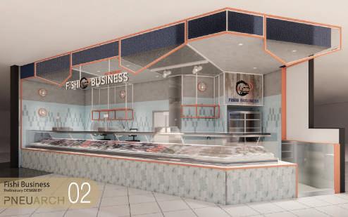
Fishi
Content
Professional Work:
Vienna Massage (Internal Fitout)
Student Work:
TAFE Design School Redevelopment
Convergence (Medihotel)
Pedal & Flipper + Coastal Rhythm
Apartments (Mixed-Use)
The Hive (Pavilion)
Construction Design:
Olympic Park Community Facility
6 - 13 14 - 23 24 - 31 32 - 37 38 - 41
1 - 5

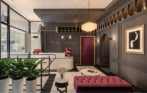
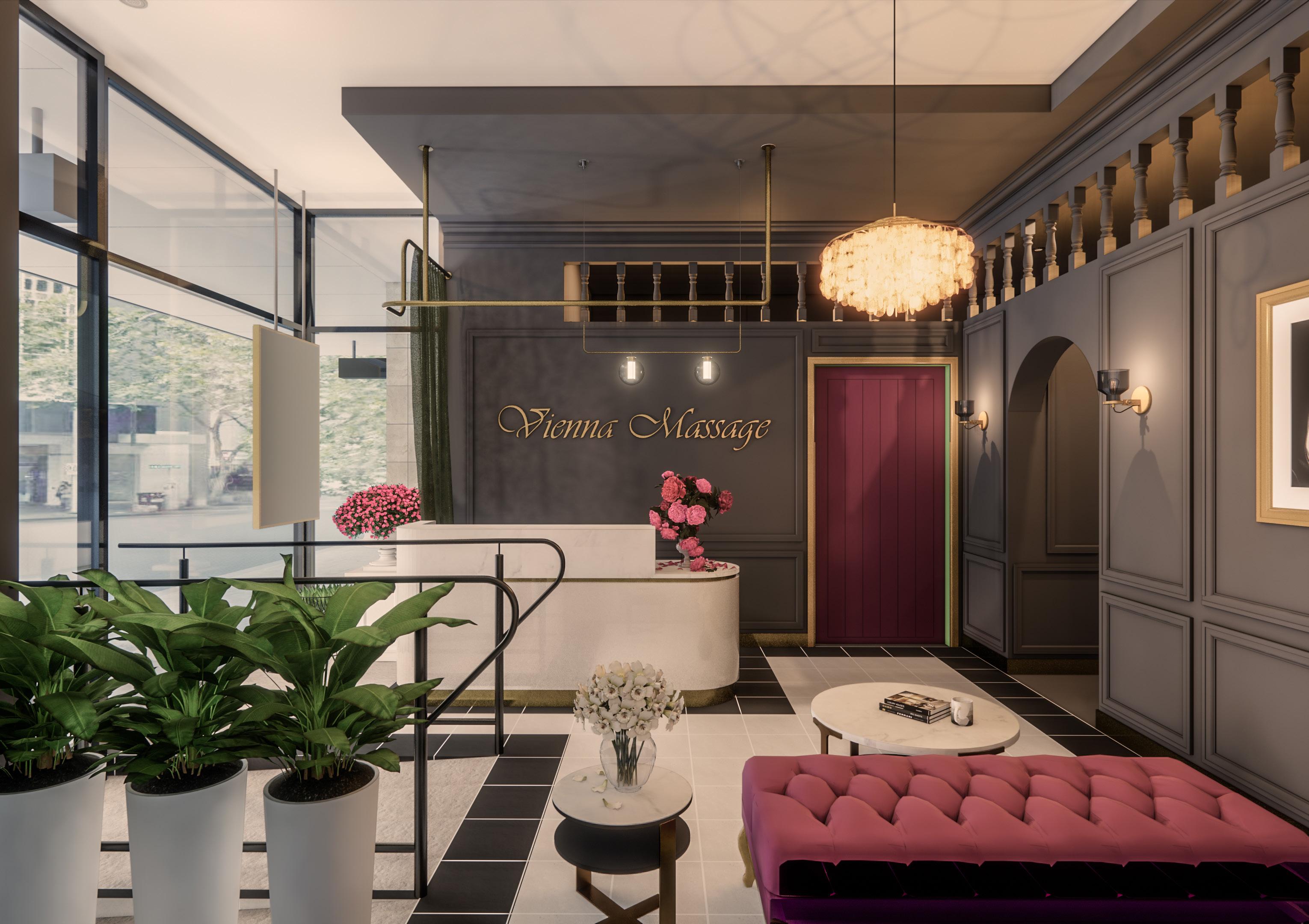
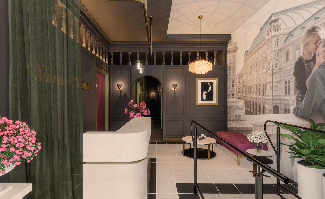
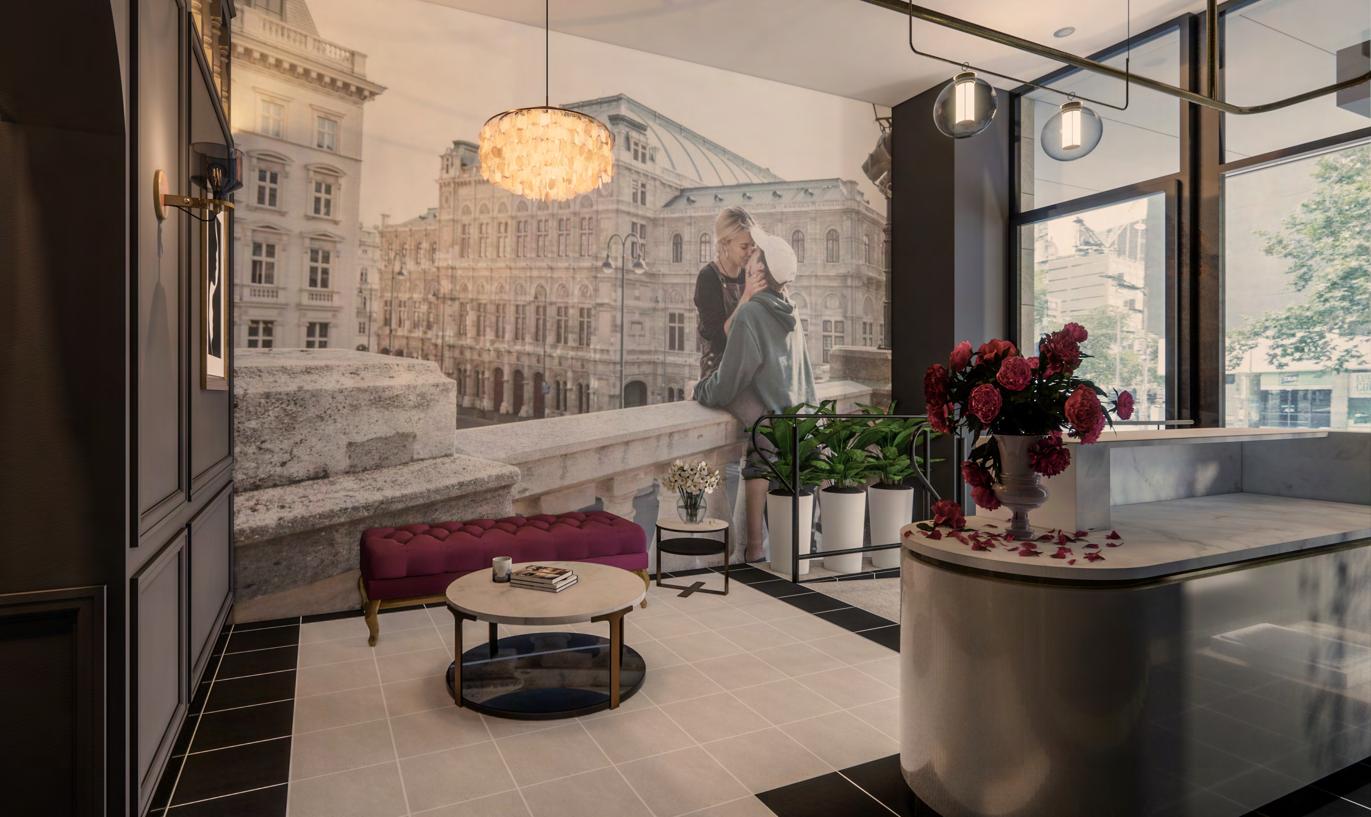
Vienna Massage
Interior Fitout
Design
by: PNEU Architects

1
Team:
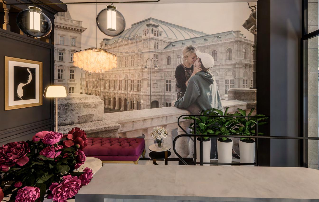
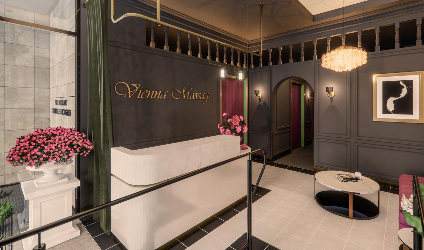
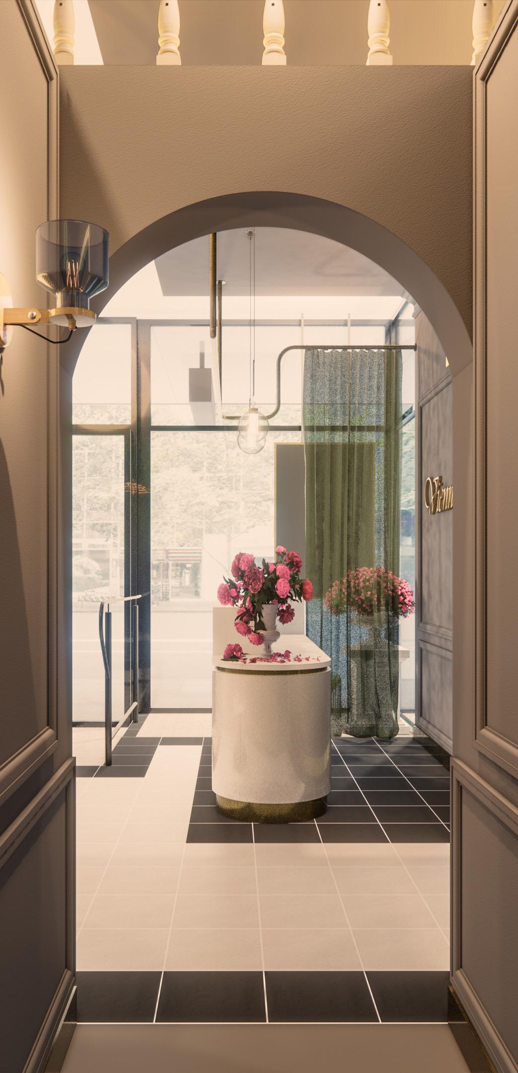
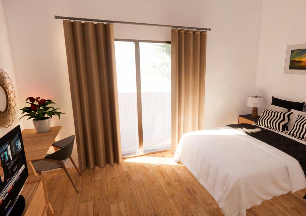
The interior of Vienna Massage is largely inspired by the Baroque-style buildings of Vienna, incorporating classical architectural features such as mouldings, ceiling cornices and fretwork into the interior. The overall colour scheme (Grey with accents of Rich Violet) and the warm, dim lighting serves to give the interior a romantic and sensual touch. Natural accents such as potted plants and flowers further amplifies the romantic aspect of the interior while helping the clients to relax and enjoy a nice massage.
Location:
Project area:
Project year:
Status:
Client:

Nelson Lee (Design, Coordination)
Nick Huyhn (Design, 3D render)
Moon Cheah (Design, Drafting, 3D render)
235 Queen Street, Melbourne.
88.14 sqm
Vienna Massage
2
2021 In construction
3

4 Selected Technical Drawings: Plan & Elevations
5
Technical Drawings: Details
Selected
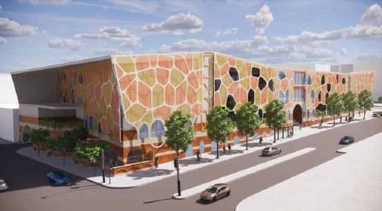
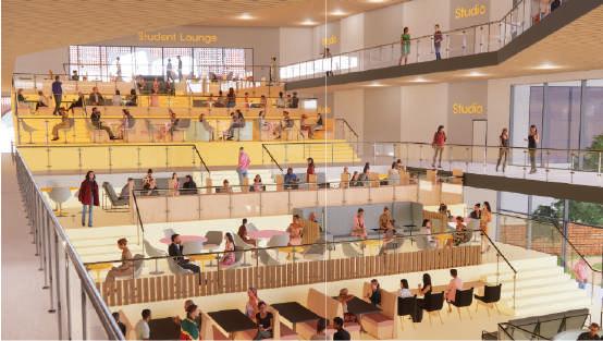
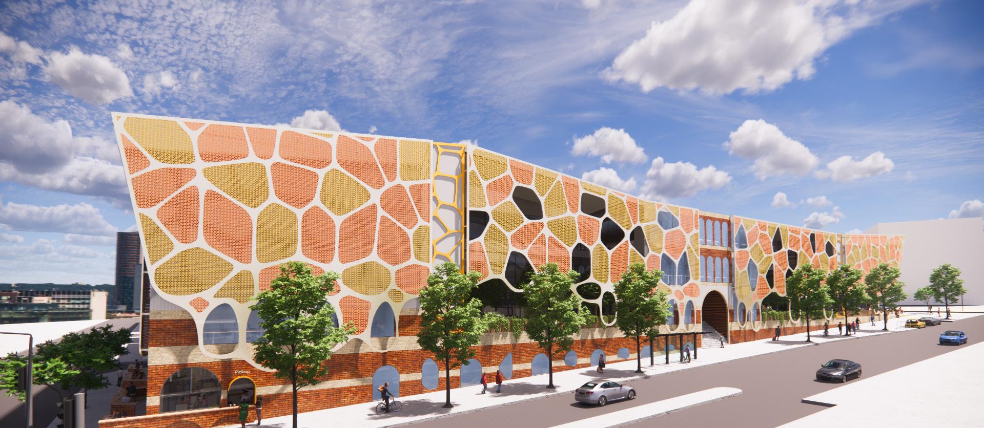
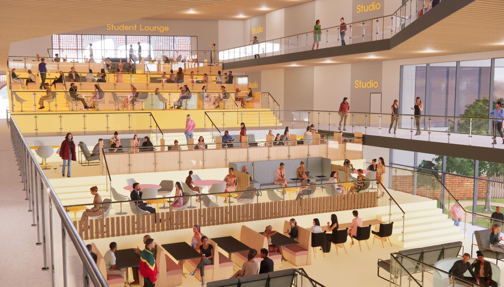
TAFE DESIGN SCHOOL REDEVELOPMENT
COWORKING SPATIAL ELEMENTS IN SUPPORTING DYNAMIC EDUCATIONAL STUDENT OUTCOMES - TAFE PERTH
How can an improved model of a school of design for TAFE with coworking spatial elements positively impact the perceived learning experience of design students in Perth?
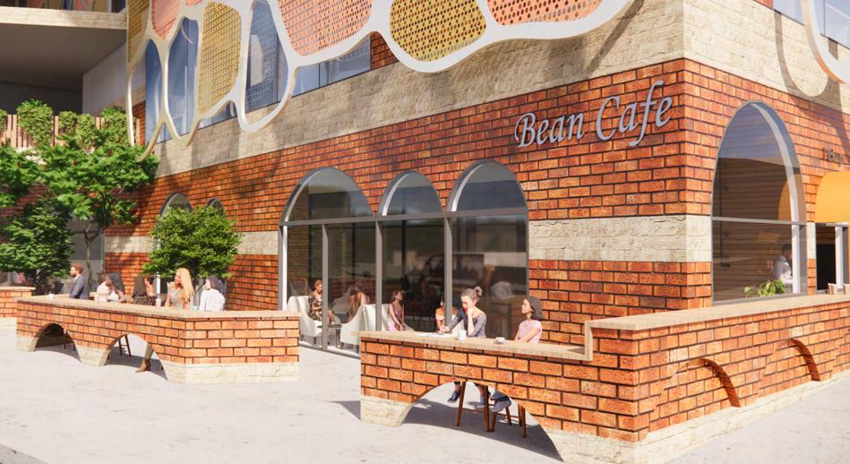
The redevelopment of TAFE Design School aspires to incorporate coworking spatial qualities into the academic environment as explored in this thesis. These qualities include flexibility, a sense of community and an inspirational atmosphere that ensures an enjoyable learning experience for design students. Situated near the Perth Cultural Centre and the entertainment hub of Northbridge, the site provides a dynamic ground plane consisting of café, retail and gallery spaces that connect the building to the rest of the campus and cultural precinct communities. Other than that, multiple courtyards with green space, bright-coloured interiors and a feature coworking terrace are included in the design proposal to provide an inspirational and vibrant learning environment. Finally, flexibility is also a very prominent part of the design, as spaces are designed with foldable walls and movable furniture that can be freely manipulated to cater for any usage or event.
Design Strategies
Subject:
Year:
Supervisor:
Lee Syminton
Site: Architectural Thesis Project 2023 Semester 2
lee.syminton@curtin.edu.au
North Metropolitan TAFE Perth Building 6, 19 Aberdeen St, Perth WA 6000
Flexibility Sense of Community Inspirational Aesthetic + Comfort
6
THE SITE
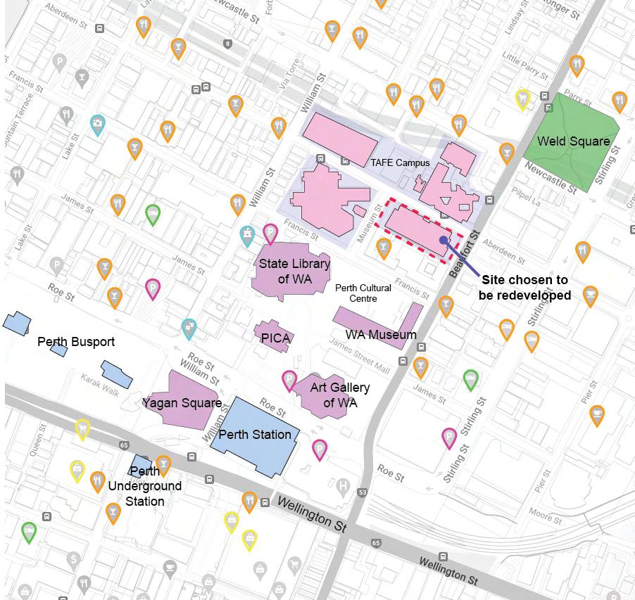
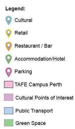
ABOUT THE SITE
SITE SELECTION
The site selected is the site of Building 6 on the TAFE North Metropolitan Perth Campus. This is because the TAFE North Metropolitan Perth campus is where all the creative and design courses take place. Furthermore, some of the buildings on the campus are quite old and outdated, including Building 6. Thus, there is a need to implement coworking spatial elements in the design of the school to provide a better learning experience for students.
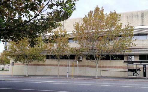
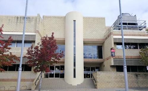
The selected site and the TAFE North Metropolitan campus is located in the middle of Perth Cultural Centre in Northbridge, surrounded by the Perth Institute of Contemporary Arts (PICA), State Library of WA, WA Museum, Art Gallery of WA and the Blue Room Theatre. Other than cultural points of interests, the site is near the entertainment hub of Northbridge where there is an abundance of bars and restaurants. Surrounded by a vibrant precinct, there is a need to reflect that liveliness and vibrancy in the design proposal as well.
Voids
Coworking Spaces
Public Interface
7
Greenery
St John’s Lutheran Church
Metropolitan
Site Area: 5796 m2
Site Dimension: 126m x 46m

ELEC. CUPBRD CW/HW EX. STAIR UP
Museum St
Aberdeen St
Beaufort St
RL 5.00
RL 3.00
Perth Mess Hall
North Metropolitan TAFE Building 7
North
TAFE Building 5
North Metropolitan TAFE Building 1
Westin College
RL 0.00
8
Scale 1:500 @ A3
SITE PLAN
Programme:
1. Carpark
2. Loading Bay
3. Lockers
4. Waste Room
5. Plant
6. Substation & Switchboard
7. Bike Parking
8. Cafe
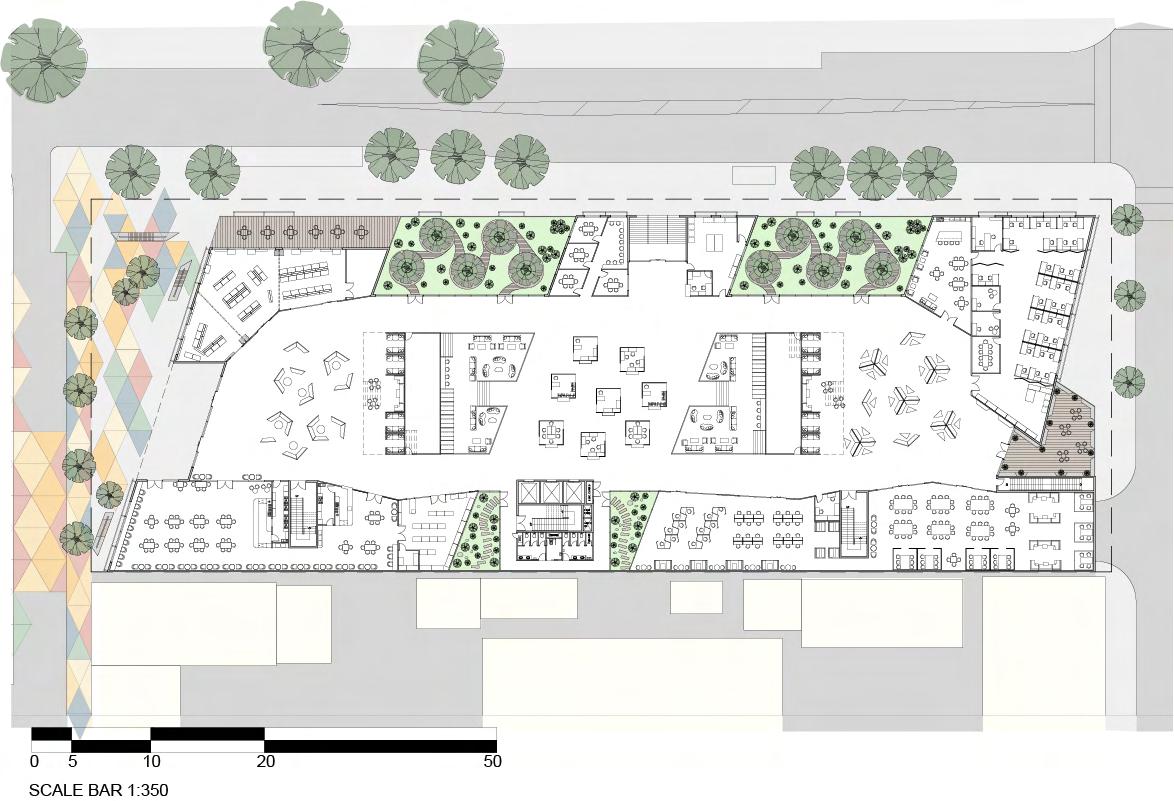
PLANS - GROUND FLOOR
Programme:
1. Main Entrance
2. Gallery
3. Lobby/Seating
4. Lunch Area/Cafe
5. Retail
6. Courtyard
7. Collab Rooms
8 . Print Room
9 . Reception
10. 2nd Entrance
11. Pop-up store
12. Cowork Terrace
13. Quiet Coworking
14. Coworking Space
15. Balcony
16. Staff Area
17. Staff Printing
18. Meeting Room
19. Quiet Room
20. Head of School Rm
21. Staff Breakout Space
22. Security Room
CW/HW MECH PRESS. 0 10 5 SCALE BAR 1:350 20 50 Museum St
St Beaufort St RL 5.00 Adjacent Building Perth Mess Hall Level Above Str RL 0.00 1 2 3 4 5 6 7 8 CW/HW MECH EX. UP UP CW/HW Museum St
St Beaufort St RL 5.00 RL 3.00 Adjacent Building Perth Mess Hall RL 0.00 Store Store Store Str Str 1 2 3 3 4 5 6 6 6 6 7 8 9 10 11 12 12 13 14 15 16 17 18 19 19 20 21 22 Scale 1:500 @ A3 9
BASEMENT
Aberdeen
Aberdeen
PLANS -
PLANS
- 2ND FLOOR (FASHION DESIGN, PRODUCT DESIGN, SPECIALIST MAKEUP)
Programme:
1. Design Studio
2. Green Screen Rm
3. Audio Studio
4. Audio Rec. Booth
5. Cowork Terrace
6. IT Studio
7. First Aid Room
8 . Technician Room
9 . Dark Room
10. Editing Room
11. Tech Workshop
12. Workshop
13. Workshop Prep Rm
14. Spray Booth
15. Dressing Room
16. TV Studio Control Rm
17. TV Studio
18. Photo Studio
19. Coworking Space
Programme:
1. Design Studio
2. Student Lounge
3. Cowork Terrace
4. Fashion Homeroom
5. First Aid Room
6. Technician Room
7. Fashion Studio
8 . Silk Screen Studio
9 . Prep Room
10. Silk Screen Wash
11. Coating Room
12. Exposure Room
13. Coworking Space
Museum St
St Beaufort St Void Void Void Void Roof Below Void Void Void Str Str Str Str Void Below UP CW/HW MECH PRESS. 1 1 1 1 1 1 2 3 5 5 5 5 6 4 6 7 8 9 10 11 12 13 14 15 15 17 18 19 16 Museum St
St Beaufort St Adjacent Building Perth Mess Hall Void Roof Below Void TV Studio Void Void Str Str Str Void Void Below Void Below Void Void DN CW/HW MECH PRESS. 1 1 1 1 3 3 1 1 4 4 7 8 9 10 13 11 12 5 6 2 Scale 1:500 @ A3 10
Aberdeen
Aberdeen
FILM, PHOTOGRAPHY, INTERIOR DESIGN)
PLANS - 1ST FLOOR (TV &
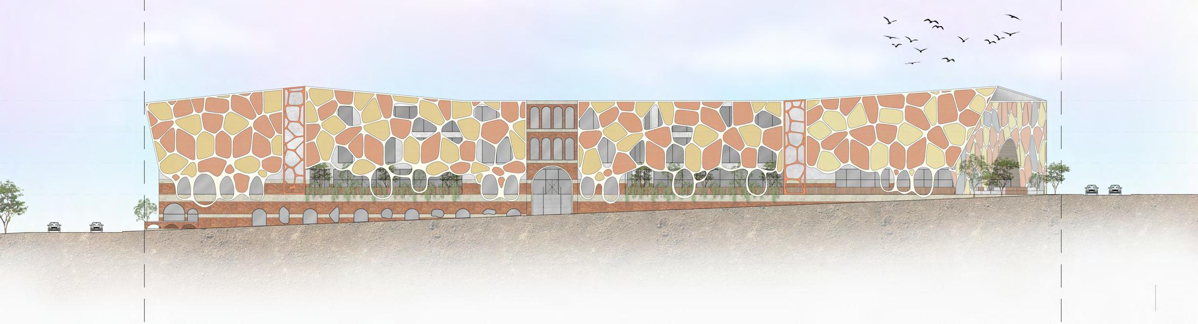
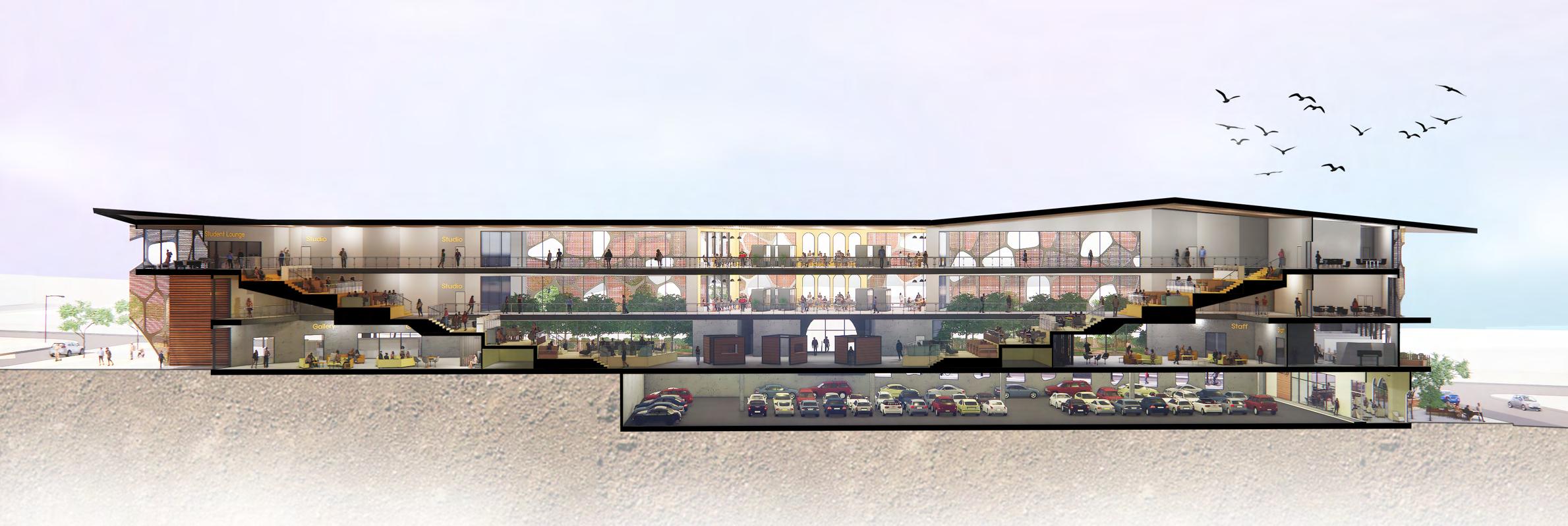
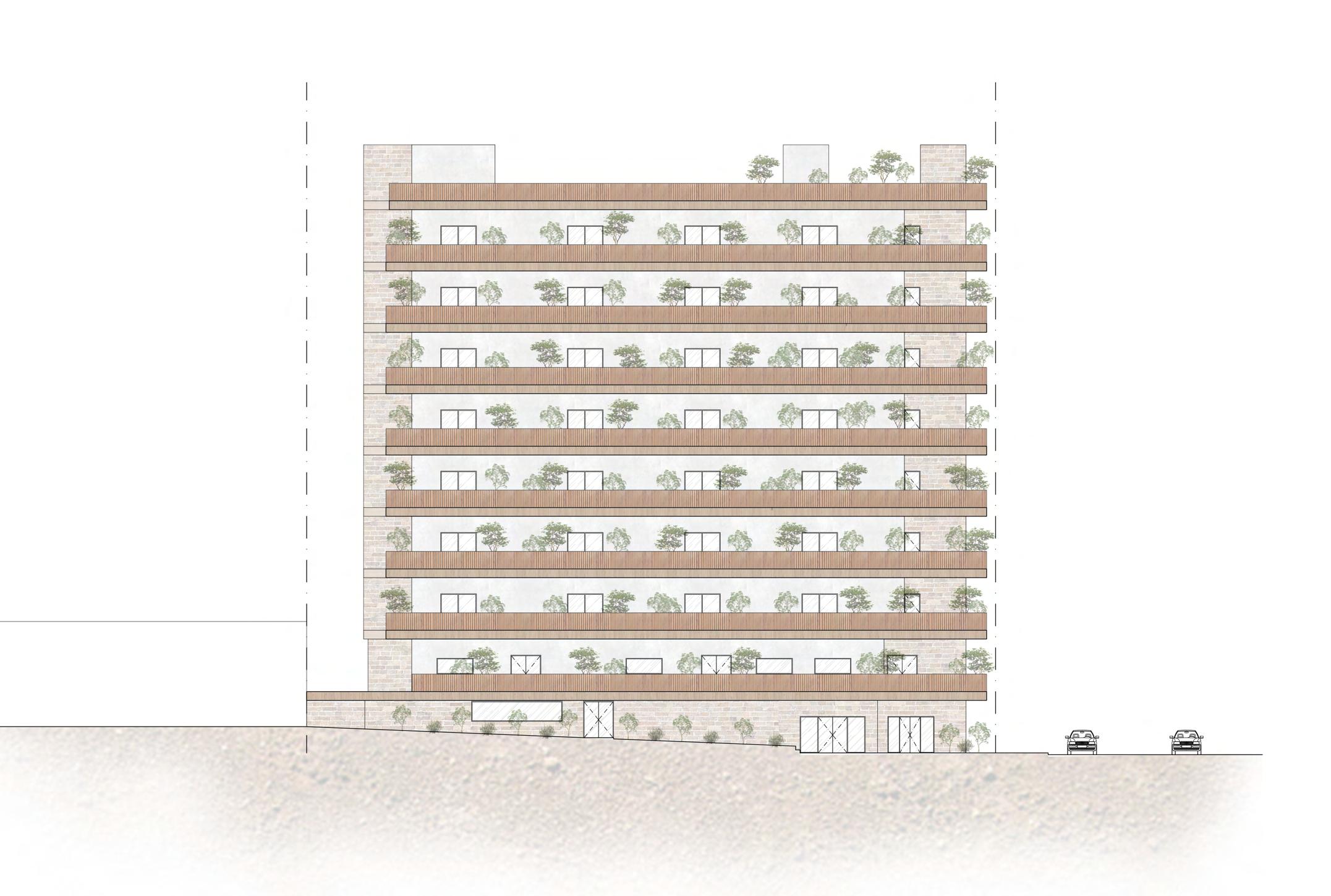
Beaufort Street RL0.00 RL5.00 RL9.00 RL13.00 Basement Ground First Second Cafe Courtyard Second Entrance Museum Street Courtyard Main Entrance Museum Street Lobby/Seating Cowork Terrace Store Store Student Lounge Lobby/Seating Carpark Pop-up store/ Cowork booths Coworking space Cowork Terrace Cafe Staff Area Beaufort Street NTS NTS 11 MAIN ELEVATION - FACING ABERDEEN STREET PERSPECTIVE SECTION
OVERALL PERSPECTIVES
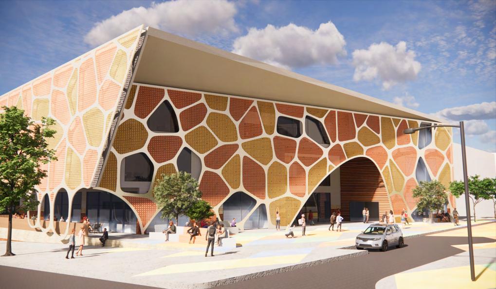
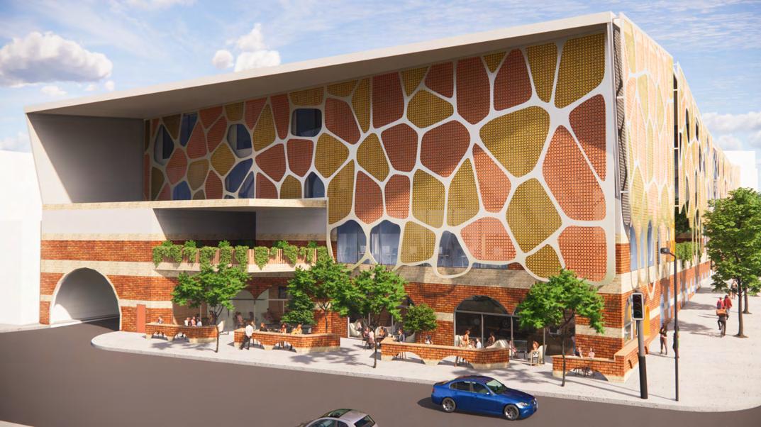
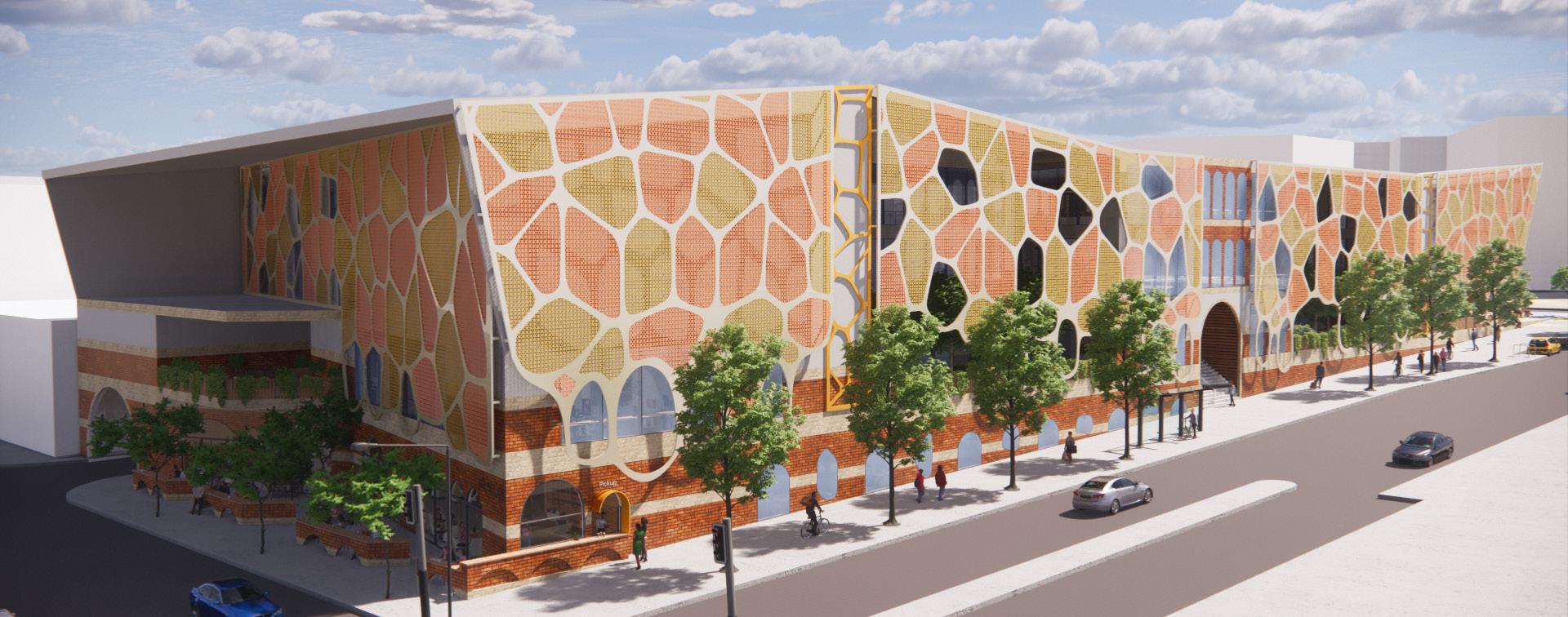
12
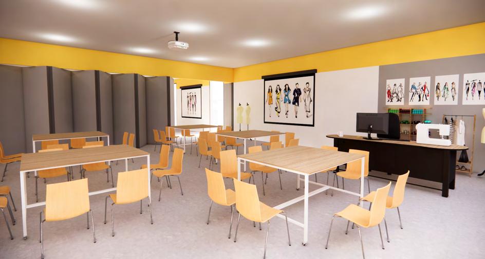
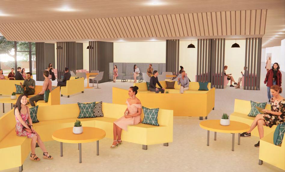
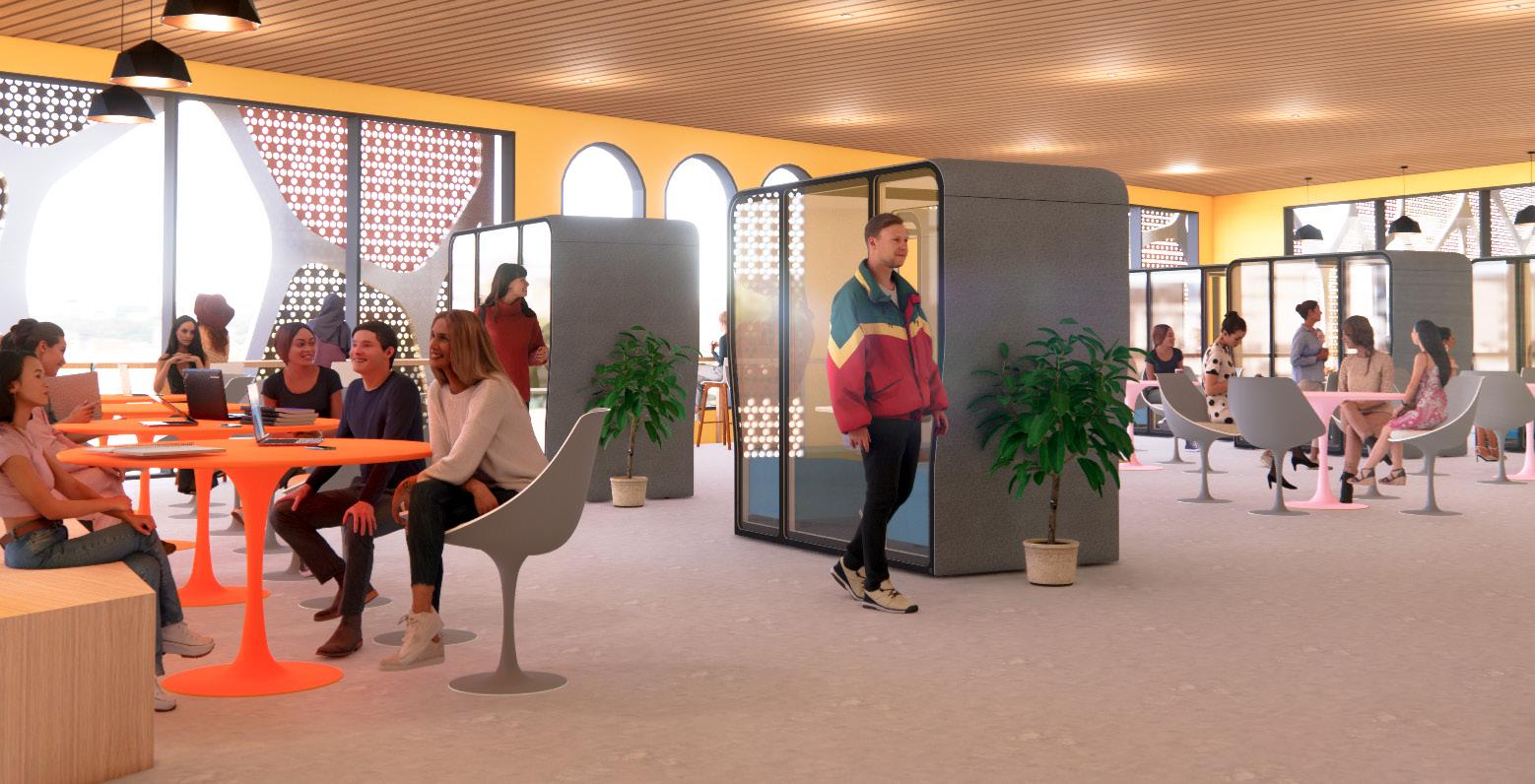
13 INTERIOR PERSPECTIVES
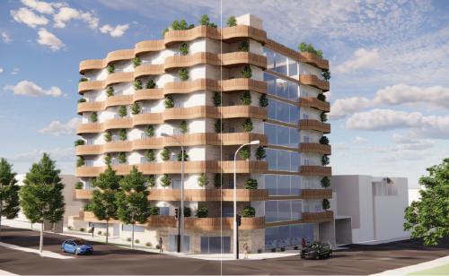
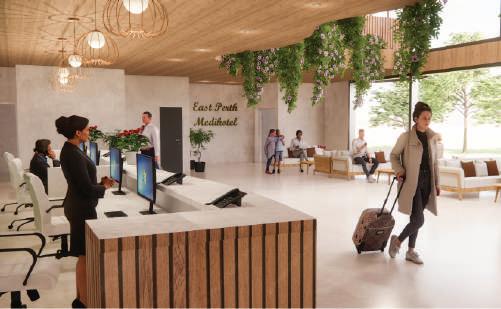
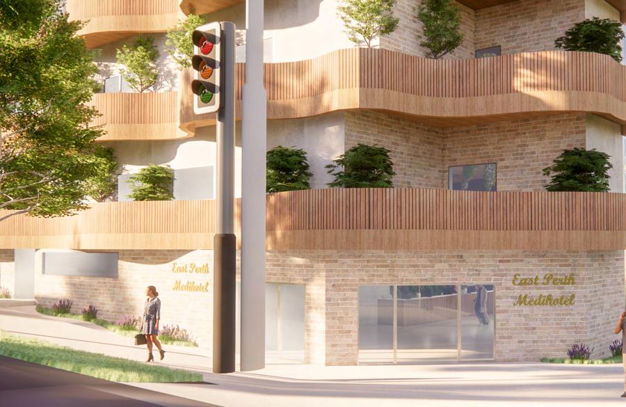
CONVERGENCE: EAST PERTH MEDIHOTEL
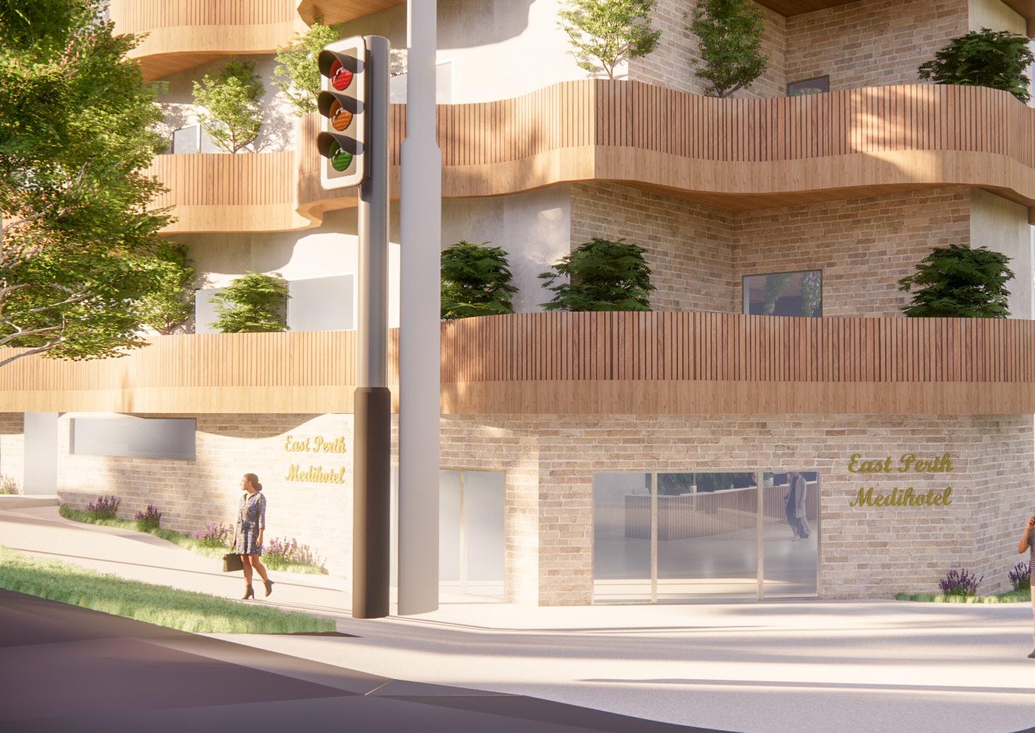
Perth Medihotel designed to act as a connection to nature and greenery. It is also to provide an oasis of health and wellness from the busy city of Perth. Main design features include a central void to allow for daylight penetration, integrated garden in the building as an extension of the greenery offered by Wellington Square, as well as the undulating terraces that offer residents multiple dynamic views.
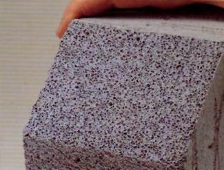
Sustainability is very crucial for this design and we have cooperated with sustainability experts, as well as engineers to find the best sustainability solution. This includes solar panels, rainwater collection system, Autoclaved Aerated Concrete (AAC Panels) and double glazing.
Subject:
Year:
Unit Coordinator:
2022 Semester 2
Site: Complex Building Studio
Parisa Izadpanahi
parisa.izadpanahi@curtin.edu.au
146 Wellington St, Perth WA
14
East Perth is an inner suburb of Perth and located next to the Perth central business district. The suburb was once an industrial area, however the redevelopment of East Perth in 1991 resulted in industrial buildings transformed into modern residential units and apartment.
There are lots of different amenities and infrastructures near the site, such as hospitals, fire station, green space etc. However, there aren’t much restaurants and cafes nearby.
Wellington Square which is near the site was formerly a swamp area rich in resource that was used by the Noongar as a camping place. Evidence show that Wellington Square was part of a rich ecosystem that provided spiritual and physical sustenance to Whadjuk as it is a major place that is connected to the creation of the world for Whadjuk. Therefore, there is a need for the building to connect to the greenery and nature provided by Wellington Square.
CONCEPT: CONVERGENCE
• To blur the boundaries between built and nature / heritage, offering health benefits to residents.
• To act as a connective tissue between East Perth and the City Centre.
DESIGN

A Connection to Nature & Greenery (Biophilia)
To provide an oasis of health and wellness.


Contrast Between Built Forms & Materials
0 0.08 0.16 0.04 km 1:2,500 04080 160 m Project Site Vehicular Roads Legend Public/Governmental Health Green Space Religious Education Wellington Square (Moort-ak Waadiny) Department of Education WA Department of Health Perth Fire Station Royal Perth Hospital Royal Perth Hospital Pathwest Perth (Royal Perth Hospital) WA Country Health Services RPH Block O Carpark Colleges & Academies 123 Hill St (Apartment) 146 Wellington St Retail The Rise:Wellington Place (Apartment) Retail & Residential Apartments Adult Community Corrections Saint Mary’s Cathedral WellingtonStreet GoderichStreet BishopsRow Lord Street
MooreStreet MooreStreet Wittenoom Street HillStreet Hill Street Bennett Street 0 0.08 0.16 0.04 1:2,500 04080 160 m Project Site Vehicular Roads Legend Public/Governmental Health Green Space Religious Education Wellington Square (Moort-ak Waadiny) Department of Education WA Department of Health Perth Fire Station Royal Perth Hospital Royal Perth Hospital Pathwest Perth (Royal Perth Hospital) WA Country Health Services RPH Block O Carpark Colleges & Academies 123 Hill St (Apartment) 146 Wellington St Retail The Rise:Wellington Place (Apartment) Retail & Residential Apartments Adult Community Corrections Saint Mary’s Cathedral WellingtonStreet GoderichStreet BishopsRow Lord Street
MooreStreet Wittenoom Street HillStreet Hill Street Bennett Street 15
VictoriaSquare
VictoriaSquare MooreStreet
DRIVERS: THE SITE
1. TOILET
2. UA TOILET
3. STORAGE
4. CATERING KITCHEN
5. DINING LOUNGE
6. LIBRARY
7. BUSINESS CENTRE / WORKSPACE
8. LUGGAGE STORAGE
9. CONVENIENCE STORE
10. CAFE
11. COURTYARD GARDEN
12. CONCIERGE
13. FRONT DESK
14. LOBBY
HILL STREET

SECTION A SECTION A SECTION B SECTION B Elevation 1 Elevation 2 PERTH FIRE STATION
HILL ST APARTMENTS WELLINGTON STREET
123
1 2 2 3 4 5 6 7 8 9 10 11 13 14 12 Scale 1:200 @ A3 16 SITE PLAN + GROUND FLOOR PLAN
GENERAL ARRANGEMENT PLAN
Basement
WELLINGTON
1st Floor
WELLINGTON
SECTION A SECTION A SECTION B SECTION B Elevation 1 Elevation 2 1 2 3 4 5 6 7 8 9 10 11 12
STREET HILL STREET SECTION A SECTION A SECTION B SECTION B Elevation 1 Elevation 2
HILL STREET 1 1 2 3 4 5 6 6 7 8 9
1:300 @ A3 17
STREET
Scale
1. TOILET
2. UA TOILET
3. STAFF OFFICE
4. STAFF BREAKOUT SPACE
5. STORAGE
6. GP CONSULTATION ROOM
7. NURSE’S STATION
8. PHARMACY
9. PHYSIOLOGY TREATMENT ROOM
1. AMBULANCE TRANSFER
2. SUBSTATION & SWITCHBOARD
3. WATER TANK & PUMP
4. LOADING BAY
5. MATERIAL HANDLING
6. WASTE ROOM
7. BIKE PARKING
8. LAUNDRY ROOM
9. END OF TRIP FACILITY
10. LOUNGE
11. SECURITY ROOM
12. PICK-UP / DROP-OFF POINT
2nd-7th floor Roof Plan
SECTION A SECTION A SECTION B SECTION B Elevation 1 Elevation 2 WELLINGTON STREET HILL STREET 1 2 2 2 2 2 2 2 3 3 3 SECTION A SECTION A SECTION B SECTION B Elevation 1 Elevation 2 WELLINGTON STREET HILL STREET 1 2 4 3
1:300 @ A3 18
Scale
GENERAL ARRANGEMENT PLAN
1. BACK OF HOUSE
2. STANDARD ROOM
3. ACCESSIBLE ROOM
1. PLANT ROOM
2. WATER TANK
3. SOLAR PV
4. ROOF GARDEN
ADJACENT BUILDING:
PERTH FIRE STATION
BOUNDARY
BOUNDARY
@ A3 19
HILL STREET
Scale 1:200
MAIN ELEVATION
Elevation 1
ADJACENT BUILDING:
PERTH FIRE STATION
BOUNDARY
BOUNDARY
1:200 @ A3 20
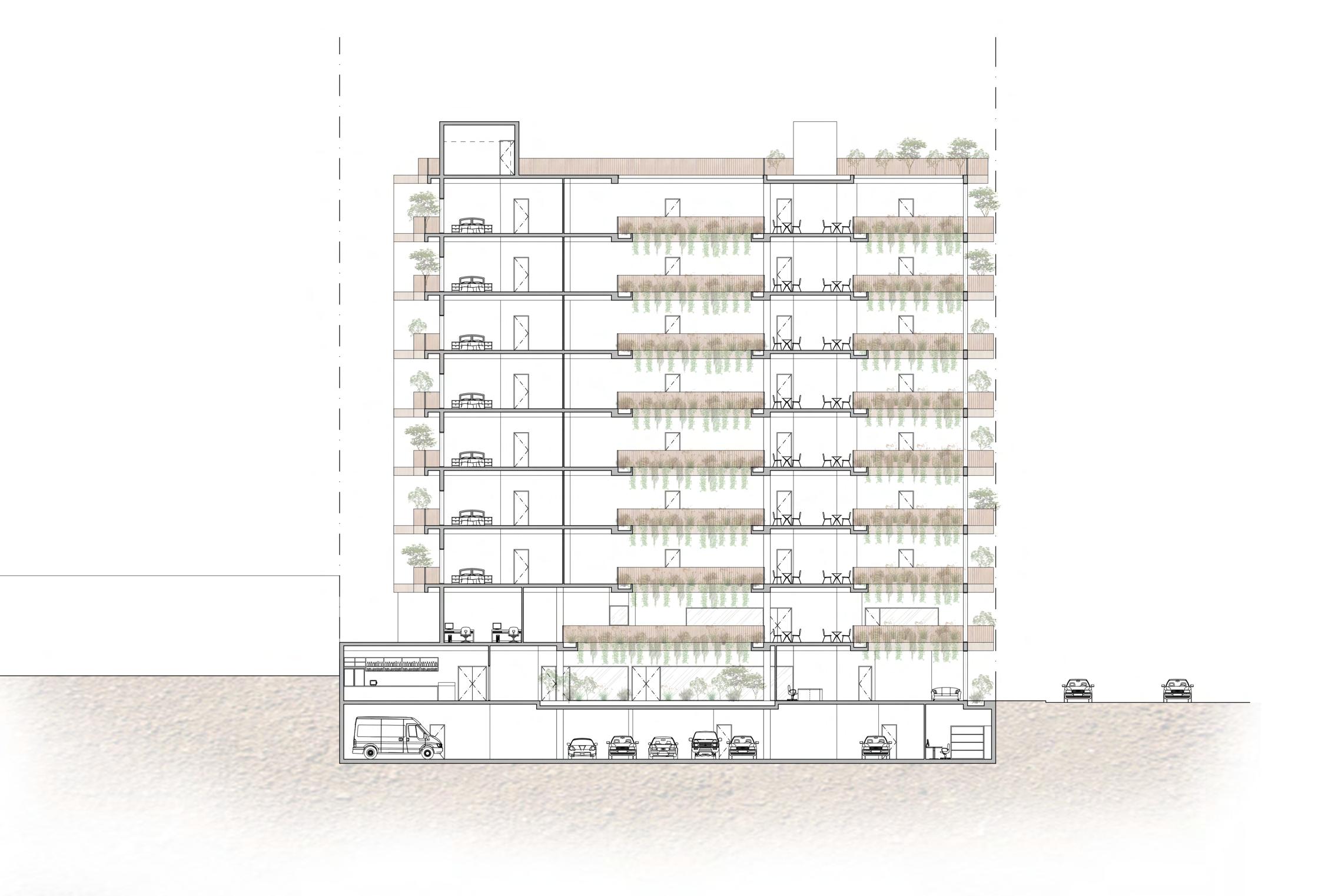
SECTION
HILL STREET
Scale
Section A MAIN
DETAILED SECTION
PARAPET FLASHING
SCUPPER DRAIN
CONCRETE SLAB
RAINWATER TANK
WATERRPROOF MEMBRANE & COMPACT CONCRETE LAYER
INSULATION
SCREED & VAPOUR BARRIER
SOLAR PANELS
(DASHED)
CEILING GLASS
PANEL
TIMBER BALUSTRADE
DRAINAGE CHANNEL
MAXIWALL AAC PANEL
STEEL FRAME, INSULATION & WATERPROOF MEMBRANE
TIMBER BALUSTRADE
STEEL STUD WALL
PLANTER
DRAINAGE CHANNEL
CONCRETE SLAB
SUSPENDED CEILING & INSULATION
SERVICES ABOVE
SUSPENDED
CEILING
PLANTER
CONCRETE SLAB
STEEL STUD WALL
Scale 1:50 @ A3 21
EXTERIOR PERSPECTIVES
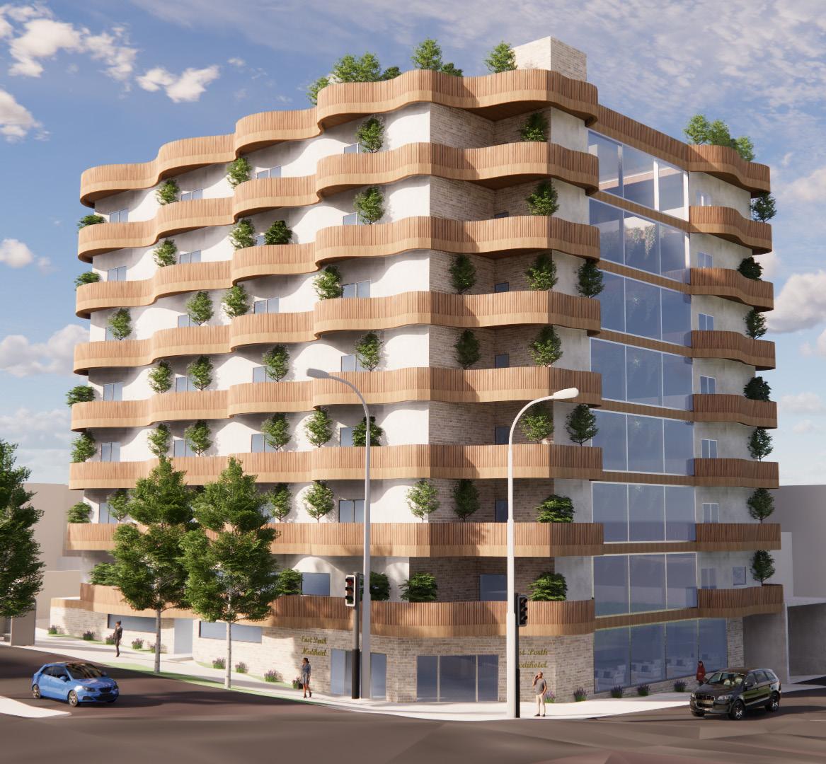
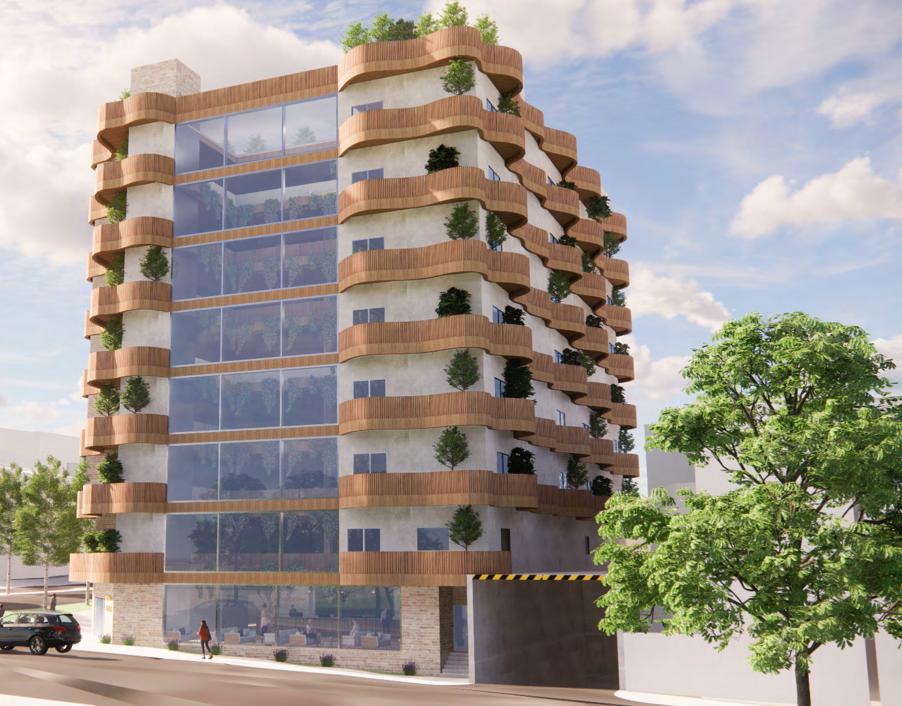
22
INTERIOR PERSPECTIVES
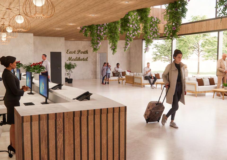
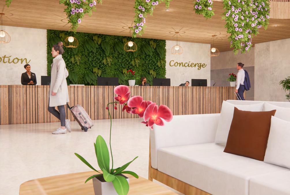
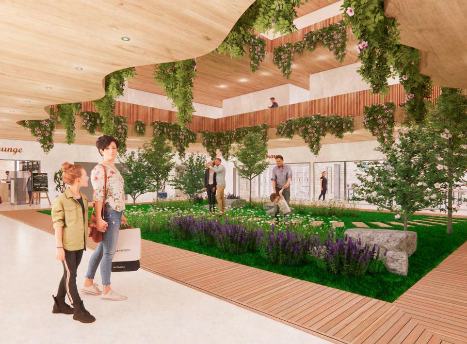
23
MIXED-USE:
Subject:
Year:
Unit Coordinator:
Site: Praxis Studio
2023 Semester 1 Lee Syminton
lee.syminton@curtin.edu.au
Pedal & Flipper Bedford Ave, Rottnest Island WA 6161
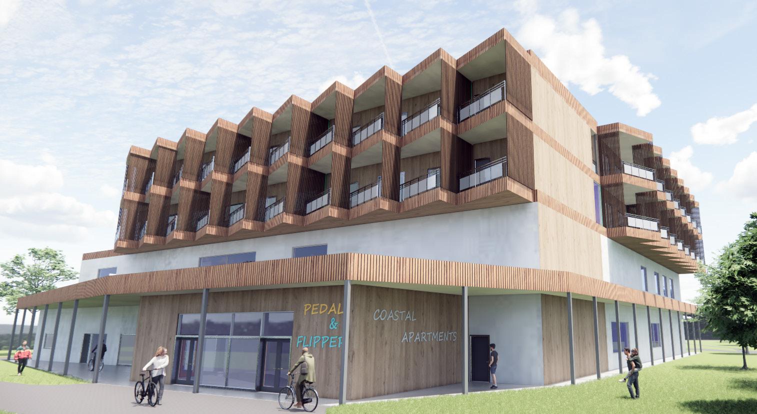
The Pedal & Flipper + Coastal Rhythm Apartments is a mixed-used building, with the lower floors consisting of the Pedal & Flipper Bike Hire and the upper floors consisting of modular apartment units. In 10 years time, the modular apartment units are to be to moved and reconfigured onto another site. In this project, architecture students collaborated with a team of engineering students to ensure the constructability of the building, as shown in the various detailed construction and technical drawings produced. Other than that, new technologies & innovation in achieving net zero and building compliances to the NCC are crucial elements that are considered in this project.
24
Site Context
Rottnest Police
Rottnest Police
Concept: Coastal Rhythm
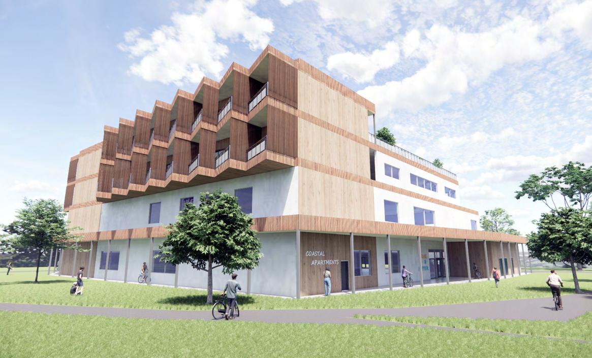
Inspired by Coastal Architecture, the concept of Coastal Rhythm means to tune into and connect to the rhythm of the coast, ocean waves and nature. The building intends to reconnect visitors to nature and of the surroundings of Rottnest, a getaway from the busy life of the city. Rhythm can be seen in the feature balconies of the apartments to mimic the waves of the ocean.
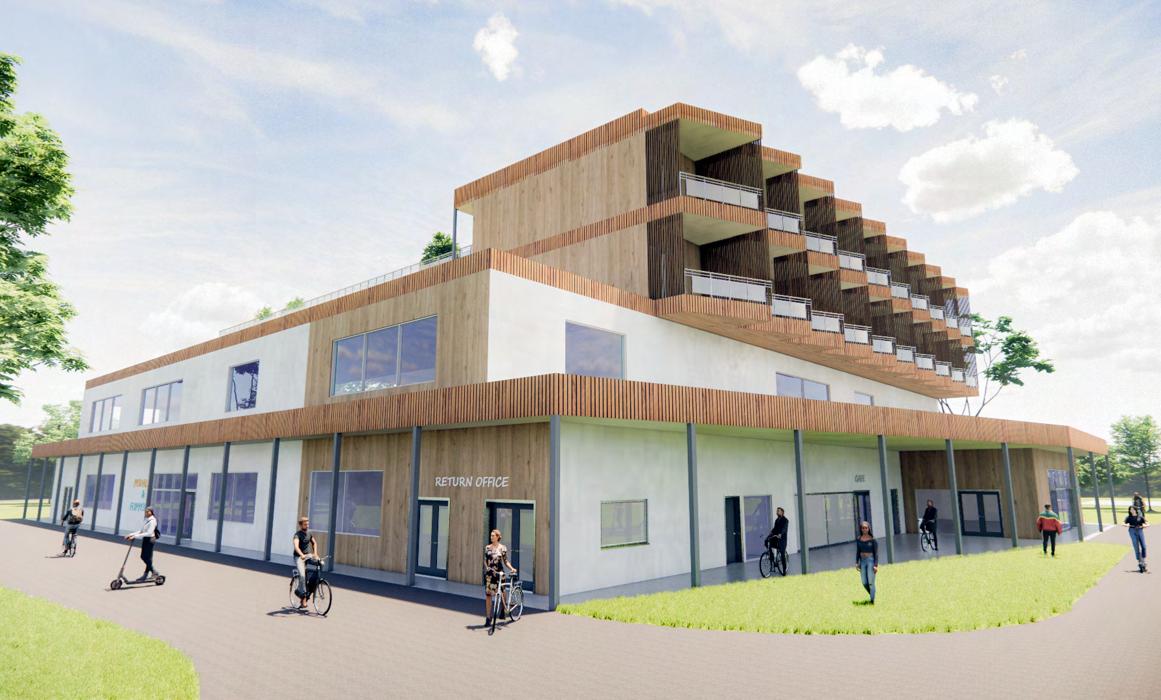
There’s also a sense of rhythm in the Peddle & Flipper building, as the layout would be streamlined so visitors can get everything they need on the way without disruption to their rhythm. This maximises their enjoyment on the island.
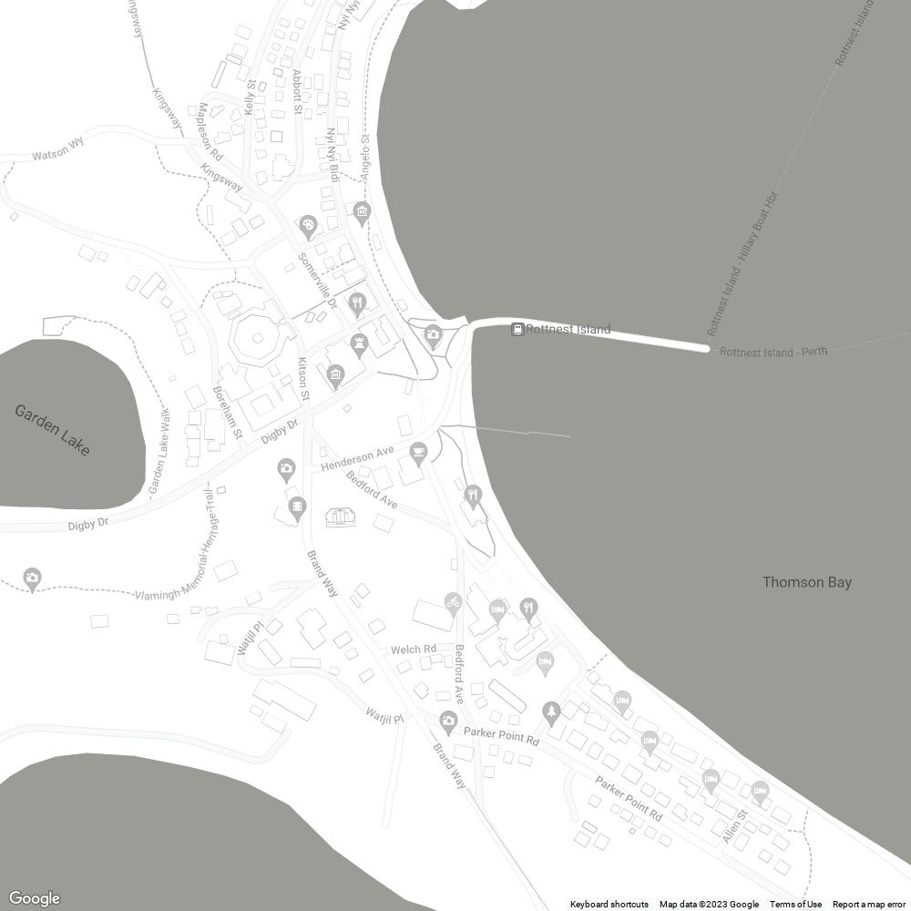
Site Plan
Rottnest Island is a famous tourist destination in Western Australia, as it is rich with sandy beaches, breathtaking scenery, woodlands, wildlife and Aboriginal history and culture. It is located 19 km from Fremantle, 33km from Perth CBD and 22km from Hillarys, reachable by ferry. The island is car-free so people get around on the local bus, or bikes. The project site of Peddle & Flipper is along the main road of Bedford Avenue, where most of the tourism and historical spots are located. To the east of the project site, there are many hotels and visitor accommodation like Hotel Rottnest.
Playground
Settlement Train
Lookout
Pilot Boathouse Thompson Bay Settlement Rottnest Island Visitor Centre Rottnest Mini Golf Rottnest Movies
Rottnest Island
Station Hotel Rottnest Segway Tours WA Project Site
Ferries / Express
Rottnest Island Fast
Wadjemup Museum
CAFE RETURN OFFICE BIKE PART STORAGE LOCKER STORAGE BIKE STORAGE MAIN ENTRY PLANT ROOM UAC WORKSHOP FLIPPER HIRE EXTERIOR WALKWAY TL01 EXTERIOR WALKWAY EXTERIOR WALKWAY C-LIFT E-BIKE BATTERIES HELMET & LOCKERS WELCH ROAD BEDFORD AVE COLEBATCH AVE BRAND WAY HOTEL ROTTNEST ROTTNEST ISLAND LAUNDRY
Public / Government Legend: Cultural / Historical Retail / Food Tourism / Entertainment Accommodation / Hotel Pilot Boathouse
Bay Settlement Rottnest Island Visitor Centre
Thompson
Rottnest Mini Golf
Hotel Rottnest
Tours
Project Site
Rottnest Island Fast Ferries / Express
Rottnest Movies
Segway
WA
Vlamingh Lookout
Wadjemup Museum
25

26
New Innovations - Materials
Exterior Perspectives
Mycelium Insulation
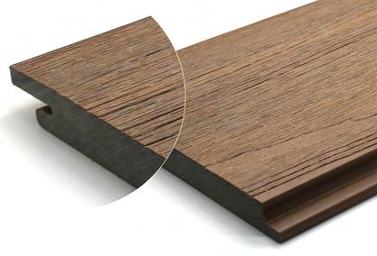
Composite Timber Cladding
Autoclave Aerated
Reconfiguration of Modular Units
Concrete
Deconstruction
Transportation
Construction
Finished Building
CAFE MALE TOILET RETURN OFFICE BIKE PART STORAGE LOCKER STORAGE BIKE STORAGE MAIN ENTRY UP UP UP UP UP PLANT ROOM UAC FIP WORKSHOP FLIPPER HIRE CAFE PREP KITCHEN FEMALE TOILET 46830 3300 6050 WIN 2730 2400 4600 WIN 3500 4600 WIN 1590 1720 DR 1560 1720 DR 830 320 2000 WIN 1720 DR 1670 1720 DR 01 D01 02 D01 01 D02 01 D02 01 D03 03 D01 01 D04 01 D05 01 D06 01 D07 02 D07 800 DR 01 D08 01 D09 02 D09 03 D09 04 D01 01 D11 05 D01 02 D04 03 D05 01 D10 02 D10 04 D09 04 D05 05 D05 03 D04 02 D05 01 W01 01 W02 01 W03 02 W04 01 W05 01 W06 02 W06 01 W07 02 W07 01 W08 02 W08 01 W09 02 W09 01 W10 02 W10 01 W11 02 W11 01 W12 02 W12 02 D08 TL01 TL01 CO01 HONED CONCRETE FINISH CO01 HONED CONCRETE FINISH TL01 CO01 CO02 CO02 EXTERIOR WALKWAY FC01 FC01 FC01 FC01 TL01 FC01 FC01 CO02 CO02 EXTERIOR WALKWAY CO02 EXTERIOR WALKWAY CO02 800290 DR 2570 6050 WIN 5710 52540 OVERALL 1500 WALKWAY 1500 WALKWAY 170 6160 90 FC01 FC01 CO01 14610 FLIPPER HIRE 90 18950 90 3110 F TOILET 90 3300 M TOILET 170 2500 UAC 90 3910 STORAGE 90 4340 LOCKER 90 2700 C-LIFT 90 8730 RETURN OFFICE 90 2730 90 4020 STAIRS 90 1800 R-LIFT 4340 PLANT ROOM 90 2100 STAIRS 430 3500 WINDOW 1720 DR 3500 WINDOW 90 2890 18950 90 30450 A B C D E F G H 1 2 3 4 5 6 7 8 42560 OVERALL 1500 WALKWAY 1500 WALKWAY 3070 1720 DR 4000 WIN 1720 DR 3640 2890 630 900 DR 1720 DR 6000 WIN 2040 2000 WIN 1000 DR 4090 2000 WIN 1430 2710 1000 DR 3710 14150 24700 170 13810 MAIN ENTRY 170 3710 170 2180 STAIRS 90 1350 90 13500 90 2020 KIT 12020 CAFE 90 90 2100 STAIRS 1360 90 7060 RETURN OFFICE 90 170 3320 FLIPPER HIRE 90 1830 1720 DR 100 90 1560 90 1900 90 1020 8000 WIN 3000 90 2020 90 R-LIFT C-LIFT R-LIFT R-LIFT C-LIFT C-LIFT 1980 R-LIFT 1550 90 90 2780 C-LIFT 90 4020 STAIRS 90 1500 WALKWAY 42560 OVERALL 1500 WALKWAY 14760 27800 4500 900 DR 2480 1720 DR 190 1720 DR 3250 920 2000 WIN 1720 DR 2000 WIN 4780 3600 WIN 2400 3600 WIN 720 1000 DR 5060 170 5990 170 3740 M TOILET 90 1500 UAC 90 4010 LOCKER 90 4900 PLANT ROOM 170 4100 STAIRS 90 1800 R-LIFT 90 90 4020 STAIRS 90 1800 C-LIFT 90 400 90 1800 C-LIFT 90 1500 STORE 90 3740 F TOILET 22340 90 4020 BIKE STORE 90 4020 WORKSHOP 90 3210 900 DR 4355 900 DR 4430 52540 OVERALL 1500 WALKWAY 1500 WALKWAY 4430 39660 8450 9380 900 DR 1500 4600 WIN 5900 4600 WIN 12780 170 1110 90 2100 STAIRS 90 5020 BIKE STORE 90 20660 WORKSHOP 90 2100 STAIRS 90 90 1800 C-LIFT 1800 R-LIFT 90 4100 STAIRS 170 1310 90 1900 R-LIFT 3390 6150 6960 WIN 1720 DR 6960 WIN 6260 1800 14530 170 SEC1 P05 SEC1 P05 E1 P04 WEST ENTRY SOUTH ENTRY 04 D01 FFL 10.00 FFL 10.00 FFL 10.00 FFL 10.00 FFL 10.00 FFL 10.00 RL 10.00 RL 10.00 RL 10.00 RL 10.00 01 W04 FH DOOR OPENING REFER DOOR SCHEDULE WINDOW OPENING REFER WINDOW SCHEDULE 170MM STEEL STUD W/ AAC CONCRETE PANEL - 50MM HEBEL POWERPANEL (EXTERNAL) - 30MM TOP HATS - 90MM STEEL STUDS W/ BIOHM MYCELIUM INSULATION - 10MM PLASTERBOARD 90MM STEEL STUD LINED W/ PLASTERBOARD OR VILLABOARD SHEETING TO WET AREAS. LEGEND 150 X 100MM RHS COLUMN 01 D01 01 W01 400 X 400MM SHS COLUMN TL01 TILES Size: 600MM X 300MM Colour: white FC01 CO01 HONED CONCRETE FINISH FIBRE CEMENT Colour: Light Grey CO02 BROOM CONCRETE FINISH FIP FIRE INDICATION PANEL FH FIRE HYDRANT + HOSE REEL + FIRE EXTINGUISHER SUBMITTED BY DRAWING NO DATE CLIENT TITLE NOTE: © COPYRIGHT MYCarchitects 2023. P02 P02 PROPOSED GROUND FLOOR PLAN 02.06.2023 MOON YAN WINDOW TAGS INDICATIVE ONLY. 1:150 @ A1 N Not to Scale Original: Scale 1:150 @ A1 27 SELECTED TECHNICAL DRAWINGS - OVERALL GROUND FLOOR PLAN
AC02 TM01 TM01 TM01 TM01 PB02 PB02 PB02 PB02 PB02 PB02 PB02 PB02 PB01 PB01 PB01 PB01 VB01 VB01 BIKE STORAGE CAFE BIKE STORAGE BED 2 BATH 2 BED 3 BED 2 BATH 2 BED 3 D4 M07 D5 M08 D6 M08 SD1 P06 400 X 400 MM SHS COLUMNS SIT ON 2000 X 2000 X 1000MM PAD FOOTINGS 1500 X 1500 X 850MM PAD FOOTINGS 200MM THK CONCRETE SLAB ON GROUND TO ENG. DRAWINGS. SUSPENDED CEILING HUNG FROM 200 X 85MM C-SECTION FLOOR JOIST @ 600 CC STEEL & GLASS BALUSTRADE 150MM THK CONCRETE SLAB WITH 350MM UPSTAND TO WITHSTAND SOIL FROM ROOF GARDEN CURTAIN WALL AROUND VOID MAIN STRUCTURE OF THE BUILDING: 400 X 400MM SHS COLUMNS AND BEAMS 200 X 85MM C-SECTION CEILING JOIST @ 1200MM CC WITH BIOHM MYCELIUM INSULATION SUSPENDED CEILING HUNG FROM 200 X 85MM C-SECTION FLOOR JOIST @ 600MM CC MAIN STRUCTURE OF THE MODULAR APARTMENTS: 150 X 100MM RHS COLUMNS & 150 X 150MM SHS BEAMS EXTERNAL WALLS OF BOTH PERMANENT STRUCTURE & MODULAR APARTMENTS: 170MM STEEL STUD WITH MYCELIUM INSULATION, CLADDED W/ AAC CONCRETE PANEL 100MM X 50MM TIMBER SCREEN ON BALCONY TO PROVIDE SHADING AND PRIVACY 120 X 45 MM CEILING JOIST @ 450MM CC KLIP-LOK 700 HI-STRENGTH ROOF SHEETING 0.48MM @ 2 PITCH ON 90 X 50MM TIMBER PURLINS ROOF GARDEN EXTERIOR WALKWAY EXTERIOR WALKWAY 75MM HEBEL POWER FLOOR AAC CONC. PANEL ON 200 X 85MM C-SECTION FLOOR JOIST W/ MYCELIUM INSULATION. TM01 LIFT LIFT GROUND FLOOR 0 1ST FLOOR 4900 2ND FLOOR 10050 3RD FLOOR 13650 ROOF 13650 RL10.00 RL14.90 RL20.05 RL23.65 RL27.65 4900 5150 3600 4000 4000 900 4000 1150 2700 900 2700 1300 5300 EXTERIOR WALKWAY 150 X 150MM SHS BEAMS & COLUMNS AAC CONCRETE PANEL CLADDING W/ SECONDARY PLYWOOD TIMBER CLADDING 100MM THK CONCRETE SLAB ON GROUND TO ENG. DRAWINGS. 170MM STEEL STUD W/ AAC CONCRETE PANEL - 50MM HEBEL POWERPANEL (EXTERNAL) - 30MM TOP HATS - 90MM STEEL STUDS W/ MYCELIUM INSULATION - 10MM PLASTERBOARD 90MM STEEL STUD LINED W/ PLASTERBOARD OR VILLABOARD SHEETING TO WET AREAS. LEGEND VB01 PB02 13MM PLASTERBOARD FINISHED W/ GREY PAINT AS SPEC. PB01 13MM PLASTERBOARD FINISHED W/ WHITE PAINT AS SPEC. TM01 COMPOSITE TIMBER CLADDING COLOUR: WALNUT AC01 HEBEL POWER PANEL AAC CONCRETE CLADDING W/ GREY RENDER 6MM VILLABOARD SHEETING FINISHED W/ WHITE PAINT TO WET AREAS AS SPEC. AC02 HEBEL POWER PANEL AAC CONCRETE CLADDING W/ SECONDARY PLYWOOD LINING ARCHITECTURE + PLANNING 120 KENT ST BENTLEY WA 6102 PEDAL & FLIPPER ROTTNEST ISLAND PROJECT SUBMITTED BY DRAWING NO DATE DRAWN BY CHECKED BY CLIENT TITLE NOTE: -Do not scale. © COPYRIGHT MYCarchitects 2023. MC MC P05 P05 SECTION 1 (SOUTH FACING) 02.06.2023 MOON YAN SCALE 1:100 @ A1 Not to Scale Original: Scale 1:100 @ A1 28 SELECTED TECHNICAL DRAWINGS - OVERALL SECTION
A B C D E F G H
BALCONY
LEGEND
LEGEND
BALCONY
DX DOOR OPENING REFER DOOR SCHEDULE
DX DOOR OPENING REFER DOOR SCHEDULE
WX WINDOW OPENING REFER WINDOW SCHEDULE .
WX WINDOW OPENING REFER WINDOW SCHEDULE
150 X 100MM RHS COLUMN
150 X 100MM RHS COLUMN
170MM STEEL STUD W/ AAC CONCRETE PANEL
170MM STEEL STUD W/ AAC CONCRETE PANEL
- 50MM HEBEL POWERPANEL (EXTERNAL)
- 50MM HEBEL POWERPANEL (EXTERNAL)
- 30MM TOP HATS
- 30MM TOP HATS
- 90MM STEEL STUDS W/ MYCELIUM INSULATION
- 10MM PLASTERBOARD
- 90MM STEEL STUDS W/ MYCELIUM INSULATION - 10MM PLASTERBOARD
90MM STEEL STUD LINED W/ PLASTERBOARD OR VILLABOARD SHEETING TO WET AREAS.
90MM STEEL STUD LINED W/ PLASTERBOARD OR VILLABOARD SHEETING TO WET AREAS.
BED 1 BATH 1 LDRY FRIDGE STORE LIVING KITCHEN 2500 ENTRY 170 1000 1090 900 D4 D1 D2 D3 D4 D5 D6 W1 290 900 D5 2980 DINING 2800 KITCHEN 6860 DINING + LIVING 170 10000 LIVING MODULE PART 1500 WALKWAY MODULE PART 1500 1500 3000 BALCONY MODULE PART 14500 OVERALL ENTRY 740 900 D2 190 900 D3 770 90 2000 BATH 1 90 3980 BED 1 600 ROBE 3380 90 600 VANITY 1670 ;LAUNDRY 1740 STORE 90 1400 90 90 420 SERVICES 90 90 510 SERV 90 SERV 170 170 1030 SHWR 1250 VANITY 1000 3280 BATH 1 1800 ROBE 90 1390 3280 BED 1 750 2000 W1 110 110 3280 LIVING + DINING 110 750 670 2170 D6 660 110 90 310 SERV 1650 90 1360 3280 KITCHEN 2050 LAUNDRY / STORE 90 1140 ENTRY 110 110 220 2880 90 1900 310 SERV 110 110 2350 900 D1 250 3500 MODULE 3500 MODULE 7000 OVERALL BALCONY BALCONY ENGINEERED TIMBER FLOORING 300 X 300MM TILES 300 X 300MM TILES CARPET ENGINEERED TIMBER FLOORING ENGINEERED TIMBER FLOORING FIBRE CEMENT FIBRE CEMENT SERV E1 M05 M05 E2 E3 M05 M06 E4 FLOOR AREA: 65.3m²
ARCHITECTURE + PLANNING 120 KENT ST BENTLEY WA 6102 PEDAL & FLIPPER COASTAL RHYTHM APARTMENTS ROTTNEST ISLAND AUTHORITY PROJECT SUBMITTED BY DRAWING NO DATE DRAWN BY CHECKED BY CLIENT TITLE NOTE: -Do not scale. -Contractor must verify all dimensions on site before commencing any work © COPYRIGHT MYCarchitects 2023. MC MC M01 1 BED + 1 BATH MODULE FLOOR PLAN 02.06.2023 MOON YAN CHEAH N SCALE 1:50 @ A3 BED 1 BATH 1 LDRY FRIDGE STORE LIVING KITCHEN 2500 ENTRY 170 1000 1090 900 D4 D1 D2 D3 D4 D5 D6 W1 290900 D5 2980 DINING 2800 KITCHEN 6860 DINING + LIVING 170 10000 LIVING MODULE PART 1500 WALKWAY MODULE PART 1500 1500 3000 BALCONY MODULE PART 14500 OVERALL ENTRY 740900 D2 190900 D3 77090 2000 BATH 1 90 3980 BED 1 600 ROBE 3380 90 600 VANITY 1670 ;LAUNDRY 1740 STORE 90 1400 90 90 420 SERVICES 90 90510 SERV 90 SERV 170 170 1030 SHWR 1250 VANITY 1000 3280 BATH 1 1800 ROBE 90 1390 3280 BED 1 750 2000 W1 110110 3280 LIVING + DINING 110 750 670 2170 D6 660 110 90310 SERV 1650 90 1360 3280 KITCHEN 2050 LAUNDRY / STORE 90 1140 ENTRY 110110 220 2880 90 1900 310 SERV 110 110 2350 900 D1 250 3500 MODULE 3500 MODULE 7000 OVERALL
ENGINEERED TIMBER FLOORING 300 X 300MM TILES 300 X 300MM TILES CARPET ENGINEERED TIMBER FLOORING ENGINEERED TIMBER FLOORING FIBRE CEMENT FIBRE CEMENT SERV E1 M05 M05 E2 E3 M05 M06 E4 FLOOR AREA: 65.3m²
ARCHITECTURE + PLANNING 120 KENT ST BENTLEY WA 6102 PEDAL & FLIPPER ROTTNEST ISLAND PROJECT SUBMITTED BY DRAWING NO DATE DRAWN BY CHECKED BY CLIENT TITLE NOTE: -Do not scale. -Contractor must verify all dimensions on site before commencing any work © COPYRIGHT MYCarchitects 2023. MC MC M01 1 BED + 1 BATH MODULE FLOOR PLAN 02.06.2023 MOON YAN CHEAH N
1:50 @ A3 Scale 1:50 @ A3 29
TECHNICAL DRAWINGS - APARTMENT MODULE FLOOR PLAN
SCALE
SELECTED
SELECTED TECHNICAL DRAWINGS - APARTMENT MODULE ELEVATION
300MM X 200MM COLORBOND BOX GUTTER ON SPANDECK GUTTER BOARD SUPPORTED BY ADJUSTABLE STRAP.
15MM COMPOSITE TIMBER CLADDING
100MM X 50MM TIMBER SCREEN ON BALCONY TO PROVIDE SHADING AND PRIVACY
MAIN STRUCTURE OF THE MODULAR APARTMENTS:
150 X 100MM RHS
COLUMNS & 150 X150MM SHS BEAMS
E3: ELEVATION 3 (NORTH)
ROOF MODULE IS TRANSPORTED SEPARATELY FROM MAIN MODULE & IS FIXED ON SITE
E4: ELEVATION 4 (WEST)
KLIP-LOK 700 HI-STRENGTH
ROOF SHEETING 0.48MM @ 2º PITCH ON 90 X 50MM TIMBER PURLINS
ENVIROSEAL WALL WRAP
VAPOUR BARRIER
400MM X 200MM COLORBOND BOX GUTTER ON SPANDECK GUTTER BOARD SUPPORTED BY ADJUSTABLE STRAP.
15MM COMPOSITE TIMBER CLADDING
50MM HEBEL POWER PANEL W/ SECONDARY PLYWOOD CLADDING
MAIN STRUCTURE OF THE MODULAR APARTMENTS:
150 X 100MM RHS COLUMNS & 150 X 150MM SHS BEAMS
ROOF MODULE IS TRANSPORTED SEPARATELY FROM MAIN MODULE & IS FIXED ON SITE
120 X 45MM CEILING JOIST @ 450MM CC W/ MYCELIUM INSULATION
MODULES TYPICALLY COME PARTIALLY CLAD TO ALLOW FOR CONNECTIONS
600MM FLOOR SPACE TO ALLOW FOR SERVICES
3000 1150 600 3600 LIVING MODULE 1150 ROOF MODULE 4750 OVERALL 900 2700 750 400
FFL
750
OVERALL D1 FFL D01
ARCHITECTURE PLANNING PEDAL & FLIPPER ROTTNEST ISLAND PROJECT SUBMITTED BY DRAWING NO DATE DRAWN BY CHECKED BY CLIENT TITLE NOTE: © COPYRIGHT MYCarchitects 2023.
2700 900 400 4750
M06
M06 1 BED + 1 BATH MODULE 02.06.2023 MOON
Scale 1:50 @
30
YAN
A3
M20 GRADE 8.8 BOLTS
BEAM & COLUMN WELDED TO 15MM THK
STEEL PLATE
150 X 150 X 5 MM RHS BEAM
150 X 100 X 5 MM RHS COLUMN
150 X 150 X 5 MM RHS BEAM
150 X 100 X 5 MM RHS COLUMN
M20 GRADE 8.8 BOLTS
135 X 100 X 5 MM RHS COLUMN WELDED TO STEEL PLATE AND BEAM
10MM STEEL PLATE
FLASHING
CANT STRIP
KLIP-LOK 700 HI-STRENGTH ROOF SHEETING 0.48MM
VAPOUR BARRIER MEMBRANE SARKING
90 X 50MM TIMBER PURLINS TO ENG.
DETAILS
150 X 100MM RHS BEAM
150 X 100MM RHS BEAM
150 X 150 X 5 MM SHS BEAM
120 X 45MM CEILING
JOIST @ 450MM CC FIXED TO 150 X 150MM SHS BEAM
BROWN COLORBOND PARAPET WALL CAPPING PACK AS REQUIRED TO ACHEIVE FALL TOWARDS BUILDING
90MM STEEL STUD WALL W/ COMPOSITE TIMBER CLADDING FIXED TO 20MM TOP HATS
MYCELIUM INSULATION
300MM X 200MM COLORBOND BOX GUTTER ON SPANDECK GUTTER BOARD SUPPORTED BY ADJUSTABLE STRAP.
KLIP-LOK 700 HI-STRENGTH ROOF SHEETING 0.48MM
90 X 50MM TIMBER PURLINS TO ENG. DETAILS
VAPOUR BARRIER MEMBRANE / SARKING OVER FLASHING
120 X 45MM CEILING
M20 GRADE 8.8
BEAM FILLET WELDED TO 10MM STEEL PLATE AND BOLTED TO COLUMN
150 X 100 X 5 MM RHS
JOIST @ 450MM CC FIXED TO 400 X 400MM SHS BEAM
150
BOLTS
COLUMN
ARCHITECTURE + PLANNING 120 KENT ST BENTLEY WA 6102 T: 04 0000 0000 F: 04 0000 0000 PEDAL & FLIPPER COASTAL RHYTHM APARTMENTS ROTTNEST ISLAND AUTHORITY PROJECT SUBMITTED BY DRAWING NO DATE DRAWN BY CHECKED BY REVISION SCALE CLIENT TITLE NOTE: -Do not scale. -Contractor must verify all dimensions on site before commencing any work -All drawings, dimensions and area calculations are approximately only and are subject to final checking and approvals by the relevant authority. © COPYRIGHT MYCarchitects 2023. MC MC M07 M07 SECTIONS AND DETAILS 1 02.06.2023 MOON YAN CHEAH D01 TYPICAL HORIZONTAL MODULE CONNECTION D02 TYPICAL VERTICAL MODULE CONNECTION D04 TYPICAL MODULE GUTTER DETAIL SCALE 1:10 @ A3 D03 TYPICAL BEAM TO COLUMN CONNECTION Scale 1:10 @ A3 31 SELECTED TECHNICAL DRAWINGS - DETAILS
X 150 X 5 MM SHS BEAM
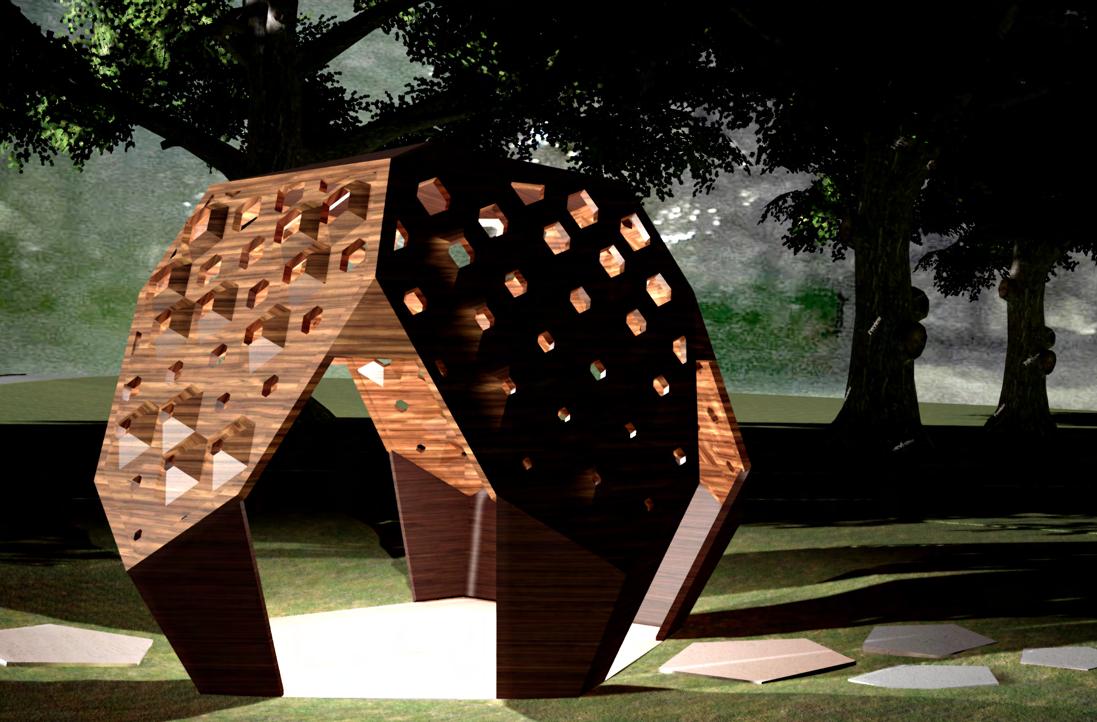
Queen Victoria Gardens Pavilion The Hive
Subject: Digital Design
Individual Work
Year: 2018 Semester 1
Tutor: Han Li
han.li1@unimelb.edu.au
Site: Queen Victoria Gardens, Melbourne
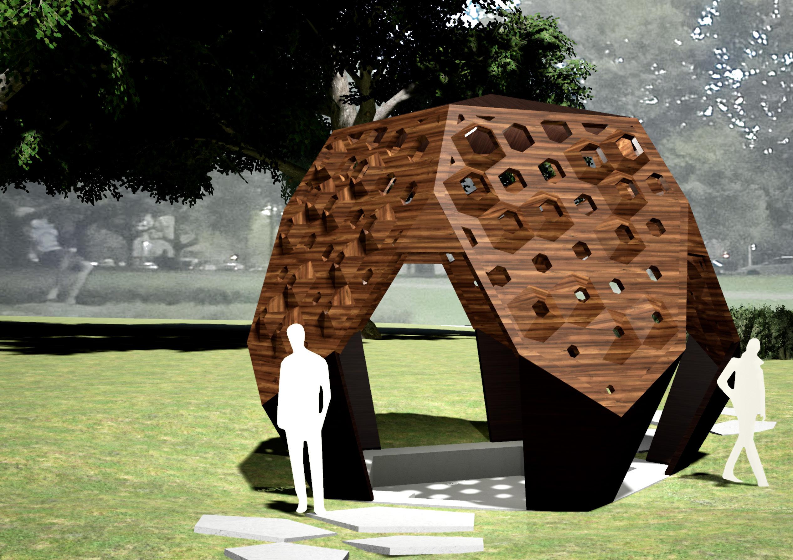
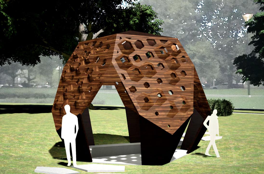
The concept of this pavilion is to create a space where people could have an interesting visual experience while inside the space. This is created by the perforated 2D and 3D panels of the pavilion, which allow sunlight to penetrate through. Since the pavilion is symmetrically centralised, sunlight could penetrate the pavilion from all directions. People could gather around and sit on the seats created by the stepping down of levels. The stairs allow people to enter the space. As for materials, the pavilion is made of timber, so that people could have a connection to nature and will also have a sense of warmth and comfort.
32
Exploded Isometric
Key:
Circulation Path
Threshold
The roof on top of the pavilion is to provide shade for the occupants inside the pavilion.
The pavilion is made out of timber, so that it has a connection to nature.
The pentagonal pathways lead to the entrances of the pavilion.
Stairs at the main entrances to allow people to descend into the pavilion.
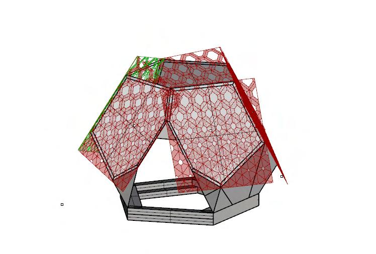
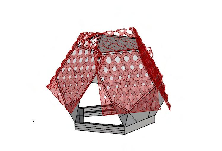
The perforations of the panels are bigger on the top and decrease in size towards the bottom to allow light into the pavilion from all directions.
The pavilion has a mix of 2D and 3D panels to give it an interesting notion.
The concrete platform of the pavilion steps down to provide an area for the lecturer or the quartet band to perform in the middle and also to provide seating areas at the sides.
33
Design Iteration
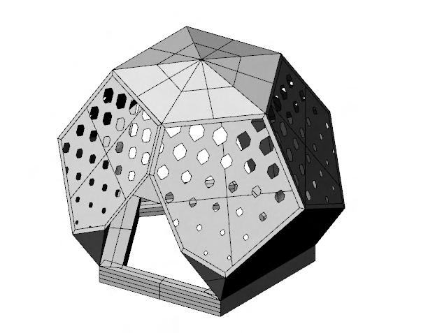
In this iteration, the pavilion is of 2D hexagonal perforations. I did not choose this because it lacks the dynamism on the exterior of the pavilion and looks very plain.
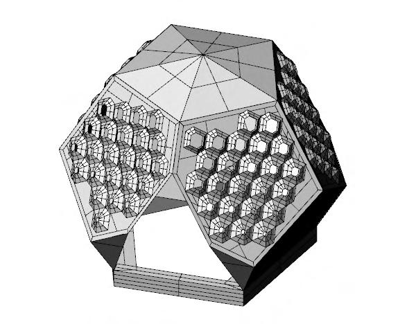
This iteration is of 3D hexagonal panels with perforations. I liked this because it creates an interesting visual experience on the exterior. However, I decide to take it a step further.
I have chosen this iteration as my pavilion design, as I have combined both 2D and 3D panels with perforations to create variation across the exterior of the pavilion. This will make the pavilion look more interesting.
34
Render Images
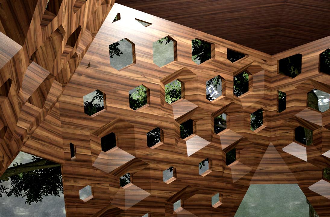
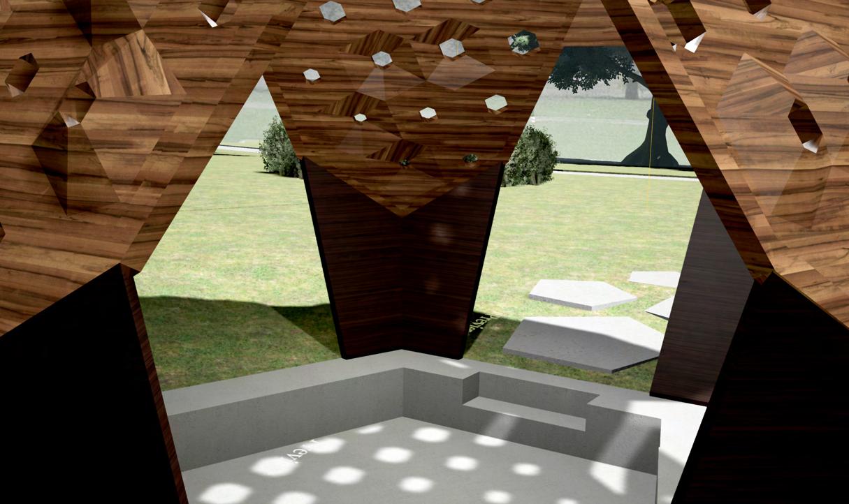
35
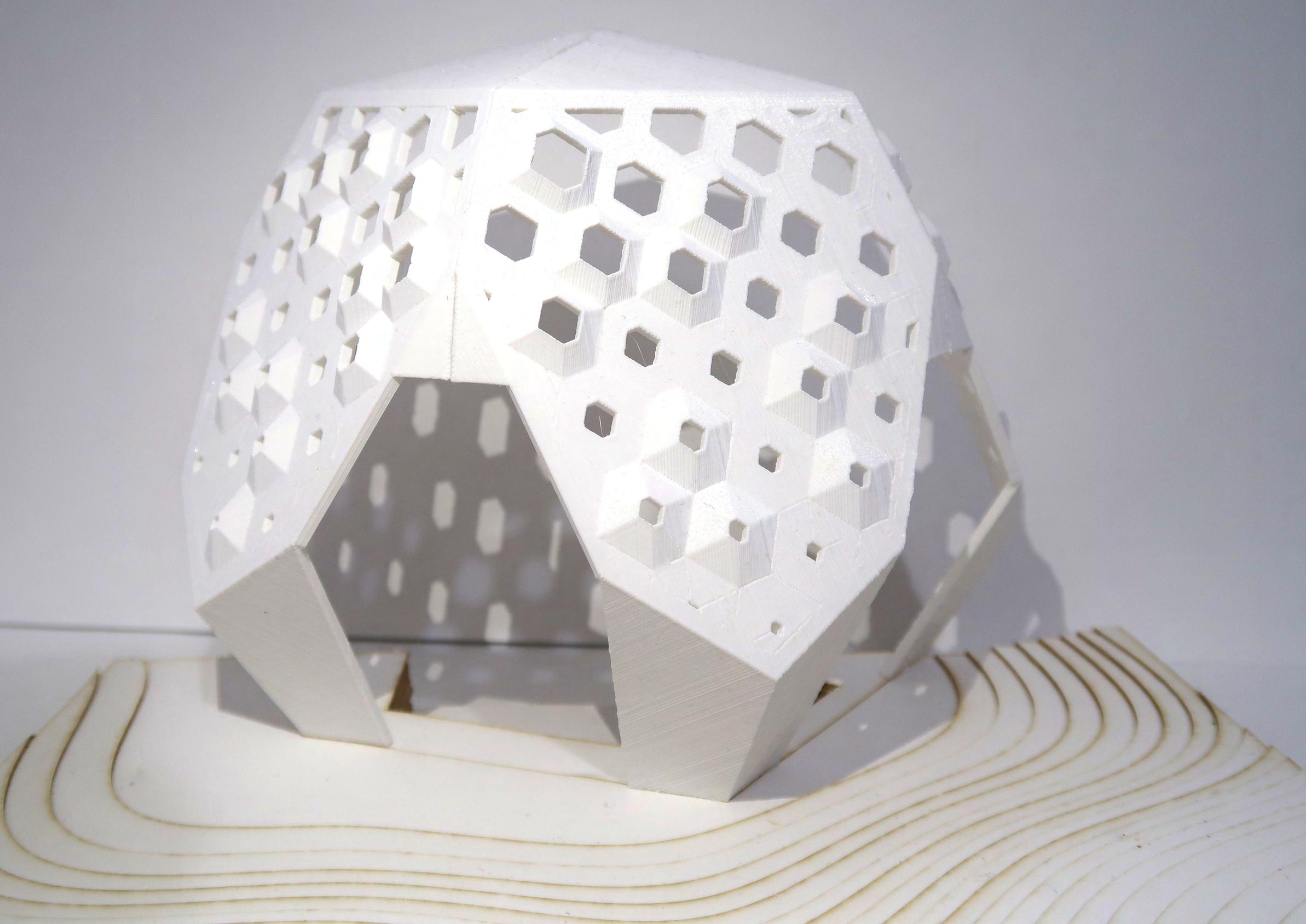
Gardens PavilionThe Hive Model
36
Queen Victoria
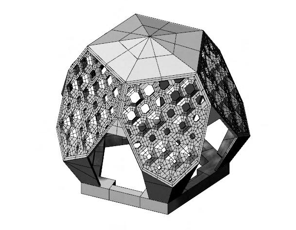
Computation Process
The computation process is done in Rhino 3D and Grasshopper.
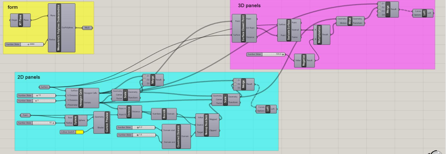
The basic form of the pavilion is created using the Weaverbird’s Polylines Dodecahedron component. The form is then scaled and further details are made, after it is baked into Rhino.

2D panels are created onto the surfaces of the structure. The Hexagon Cells component is used to make hexagonal panels. Then, the variation in perforation size of the panels are made using a point attractor and the Scale component.
3D panels are created by offsetting the geometry lines of the perforations with the Move component and then lofting the hexagonal cells with the geometry lines together. The final product is a mix of 3D and 2D panels, where the changes are made in Rhino.
37
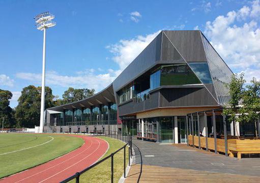
Construction Design
Olympic Park Community Facility
by Croxon Ramsay
Subject: Construction Design
Individual Work
Year: 2019 Semester 1
Tutor: David Ash
david.ash@unimelb.edu.au
Site: Olympic Park Community Facility, Melbourne, VIC
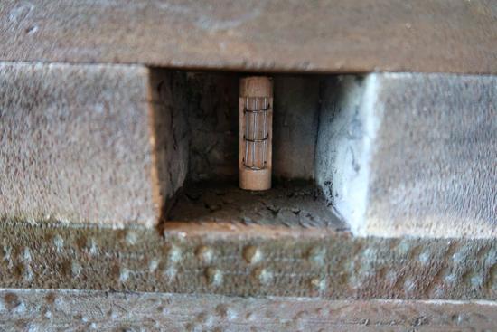
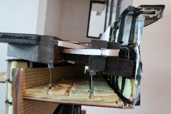
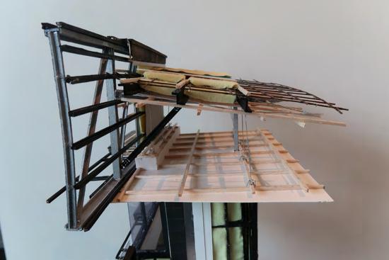
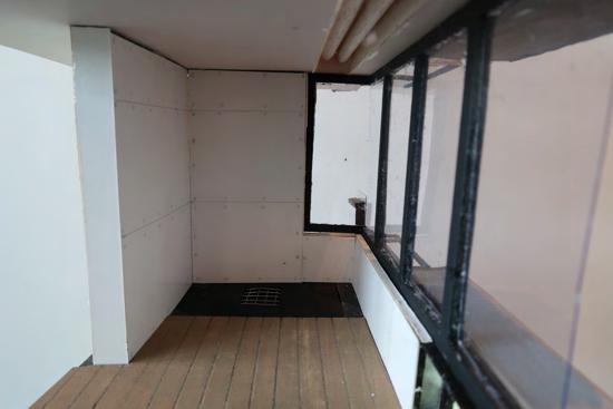
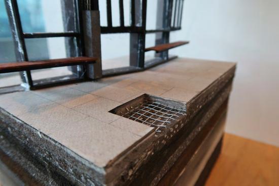
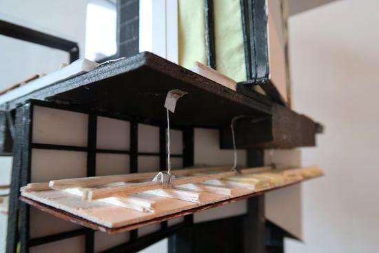
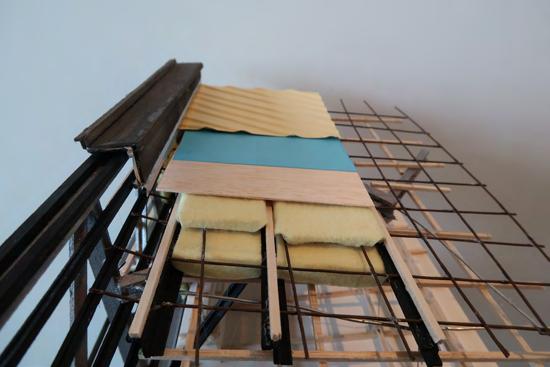
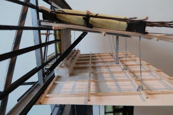
In this subject, axonometric drawings and a physical model of an allocated section was produced with the aid of construction drawings of the Olympic Park Community Facility by Croxon Ramsay. Various construction elements and processes are learnt throughout this subject.
38
Axonometric Drawing 1
NAME: MOON YAN CHEAH
STUDENT NUMBER: 885869
FFLRL10.70
TUTORIAL GROUP: 19
TUTOR NAME: DAVID ASH
CLRL9.50
GROUND FLOOR
Legend Wall
1.Brickwork type 2 - Austral Bowral50
2.Insula�on type 2- 88mm Thick Soundscreen
3.Cold Formed Stud Framing- Nom. 150 x 45 or 90 x 45
4.Plasterboard - 10mm Thick
Ceiling
5.Metal Cladding - VM Zinc Flat Lock Seam Panel System
6.Folded Soffit Flashing- Breather Member, Ply substrate and galvanised s�ffeners as required
7.Suspended �mber cladding- Blackbu� Decking Boards, 64x20mm
8.Insula�on type 4- Gold Ba�s 215mm thick
9.Insula�on type 2- 88mm Thick Soundscreen
10.Vapour Permeable Membrane type 1- ProctorWrap Commercial
FIRST FLOOR
Floor
11. Post tensioned floor beam - 1B3 R.C. beam - 700x600mm - 1B14 R.C. beam- 600x400mm
12. Post tensioned beam reinforcement:
(a)Top-2N16(T05)T2(7275),2N16(T23)T2(X6700), 9N16(T32)T1(X7000)
(b)Bo�om-2N16(B20)B2(X6000),4N12(B03)B2(X3300), 5N12(B17)B2(X 6000)
13. Post tensioned concrete slab- 220mm thick
14. Post tensioned slab reinforcement:
(a)Top- N12-300(B,B1), N12(T28)-400T1(X3050)
(b)Bo�om- 12N (B18)-400 B2(X7000), 2N12(B32)B2(X2500)
15. R.C. Column type E
16. R.C. Column reinforcement- 14N20 bars with R10 ligs @200 centres
17. Post tension tendon- Live End Encourage and dead end encourage.
18. Timber flooring- 189x20mm American White Oak Timber flooring
19. Window- Powdercoat PWC 1 External Window Framing System
20. Glass Type 5- Thermotech IGU
PROJECT NAME: TASK 2A
SECTION: C
SCALE : 1:10 @A1
PARK COMMUNITY FACILITY BY CROXON RAMSAY
OLYMPIC
15 17 18 19 20 16 14 13 12 12 11 11 10 9 8 7 6 5 4 3 2 1 39
Axonometric Drawing 2
First Floor Ceiling
Suspended Ceiling System(SC2)
-Rondo Key-Lock System
1. Plasterboard (10mm thick)
2. Furring Channels (28mm)
3. Top Cross Rail (25mm)
4. Suspension clips
Roof
TOPRL16.84
LEVELCL-RL13.75
1. Plasterboard (10mm thick)
2. Furring Channels (28mm)
3. Top Cross Rail (25mm)
4. Suspension clips
Roof
First Floor Ceiling
5. Insula�on (IN3)-100mm Permastop (R2.5) building blanket adhered with heavy duty foil sisala�on
Suspended Ceiling System(SC2)
6. Insula�on (IN4)- Gold Ba�s 215mm thick (R4.1)
-Rondo Key-Lock System
7. 'Roof Rack' thermal spacer (75mm)
1. Plasterboard (10mm thick)
2. Furring Channels (28mm)
3. Top Cross Rail (25mm)
8. Plywood backing (18mm)
9. Safety mesh (under IN3)
4. Suspension clips
10. Roof Sheet- Lysaught Kliplock 406, 3° pitch
Roof
11. Z purlins- Connected to RB4(not shown) with 8 cleat plate, 6 CFW 2M12 4.6/S bolts
5. Insula�on (IN3)-100mm Permastop (R2.5) building blanket adhered with heavy duty foil sisala�on
5. Insula�on (IN3)-100mm Permastop (R2.5) building blanket adhered with heavy duty foil sisala�on
7. 'Roof Rack' thermal spacer (75mm)
8. Plywood backing (18mm)
9. Safety mesh (under IN3)
12. Roof Beam B4- 150 UC 23, connected to RT5 ver�cals with 12 cleat plate, 6 CFW 2M20 8.8/S bolts
6. Insula�on (IN4)- Gold Ba�s 215mm thick (R4.1)
7. 'Roof Rack' thermal spacer (75mm)
8. Plywood backing (18mm)
6. Insula�on (IN4)- Gold Ba�s 215mm thick (R4.1)
13. Diagonal Brace- 75x10 EA, connected to B4 and RT5 with 12 cleat plate, 6 CFW 2M20 8.8/S bolts
9. Safety mesh (under IN3)
10. Roof Sheet- Lysaught Kliplock 406, 3° pitch
14. Top Chord-180 PFC
15. Bo�om Chord- 180 PFC
11. Z purlins- Connected to RB4(not shown) with 8 cleat plate, 6 CFW 2M12 4.6/S bolts
16. Diagonals- 75x6 EA
10. Roof Sheet- Lysaught Kliplock 406, 3° pitch
Steel Truss (RT5)
12. Roof Beam B4- 150 UC 23, connected to RT5 ver�cals with 12 cleat plate, 6 CFW 2M20 8.8/S bolts
17. Ver�cals- 150 UC 23
18. Spacers
13. Diagonal Brace- 75x10 EA, connected to B4 and RT5 with 12 cleat plate, 6 CFW 2M20 8.8/S bolts
11. Z purlins- Connected to RB4(not shown) with 8 cleat plate, 6 CFW 2M12 4.6/S bolts
19. Steel Framing
14. Top Chord-180 PFC
15. Bo�om Chord- 180 PFC
12. Roof Beam B4- 150 UC 23, connected to RT5 ver�cals with 12 cleat plate, 6 CFW 2M20 8.8/S bolts
20. Insula�on (IN1) 110mm Thick Soundscreen (R3.1)
21. Vapour Permeable Membrane (VPM1)- ProctorWrap Commercial
16. Diagonals- 75x6 EA
17. Ver�cals- 150 UC 23
22. Masonsite Lining
18. Spacers
13. Diagonal Brace- 75x10 EA, connected to B4 and RT5 with 12 cleat plate, 6 CFW 2M20 8.8/S bolts
14. Top Chord-180 PFC
15. Bo�om Chord- 180 PFC
16. Diagonals- 75x6 EA
17. Ver�cals- 150 UC 23
18. Spacers
19. Steel Framing
23. Folded MC3 Parapet flashing
19. Steel Framing
20. Insula�on (IN1) 110mm Thick Soundscreen (R3.1)
24. Insect Screen
21. Vapour Permeable Membrane (VPM1)- ProctorWrap Commercial
22. Masonsite Lining
Steel Truss (RT5)
23. Folded MC3 Parapet flashing
24. Insect Screen
Facade
25. Metal Cladding (MC2)
Facade
20. Insula�on (IN1) 110mm Thick Soundscreen (R3.1)
25. Metal Cladding (MC2)
21. Vapour Permeable Membrane (VPM1)- ProctorWrap Commercial
22. Masonsite Lining
23. Folded MC3 Parapet flashing
24. Insect Screen
VMZinc Ver�cal Interlocking Panel System, 300mm Panel Width, 24mm Panel Depth
26. Metal Cladding (MC3)
VMZinc Ver�cal Interlocking Panel System, 300mm Panel Width, 24mm Panel Depth
26. Metal Cladding (MC3)
VMZinc Flat Lock Seam Panel System
VMZinc Flat Lock Seam Panel System
Facade
25. Metal Cladding (MC2)
26. Metal Cladding (MC3)
VMZinc Flat Lock Seam Panel System
27. Plywood backing Panels(18mm)- Installed in conjunc�on with MC3
27. Plywood backing Panels(18mm)- Installed in conjunc�on with MC3
28. An� abrasive building paper- between MC3 and plywood backing
28. An� abrasive building paper- between MC3 and plywood backing
29. Vapour Permeable Membrane (VPM1)ProctorWrap Commercial
30. Vapour Permeable Membrane (VPM2)ProctorWrap High Tensile Roof
29. Vapour Permeable Membrane (VPM1)ProctorWrap Commercial
VMZinc Ver�cal Interlocking Panel System, 300mm Panel Width, 24mm Panel Depth
31. Steel Hood Canopy Framing- SHS
30. Vapour Permeable Membrane (VPM2)ProctorWrap High Tensile Roof
32. Outrigger- 75x 6 EA (connected to RT5 bo�om chord) @1000 max CTS ,6 CFW)
33. Formed drip groove
31. Steel Hood Canopy Framing- SHS
34. Breather Membrane (BM)- Proctor Geo HC9 Mat
35. Spacer
27. Plywood backing Panels(18mm)- Installed in conjunc�on with MC3
32. Outrigger- 75x 6 EA (connected to RT5 bo�om chord) @1000 max CTS ,6 CFW)
33. Formed drip groove
28. An� abrasive building paper- between MC3 and plywood backing
29. Vapour Permeable Membrane (VPM1)ProctorWrap Commercial
30. Vapour Permeable Membrane (VPM2)ProctorWrap High Tensile Roof
31. Steel Hood Canopy Framing- SHS
34. Breather Membrane (BM)- Proctor Geo HC9 Mat
35. Spacer
OFNORTHPARAPET
TOPRL16.84
2
Steel Truss (RT5) 15 17 18 19 20 21 22 23 24 25 26 27 28 29 30 31 32 33 34 35 16 14 13 12 11 10 9 8 7 6 5 4 3 3 2 2 1
OFNORTHPARAPET
LEVELCL-RL13.75
15 17 18 19 20 21 22 23 24 25 26 27 28 29 30 31 32 33 34 35 16 14 13 12 11 10 9 8 7 6 5 4 3 3 2 2 1
OFNORTHPARAPET
TOPRL16.84
15 17 18 19 21 22 23 24 16 14 13 12 11 9 7 6 5 4 3 3 2 2 1 40
Model Photographs
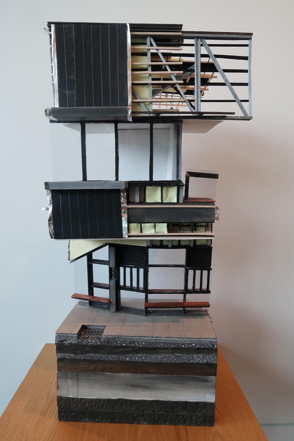
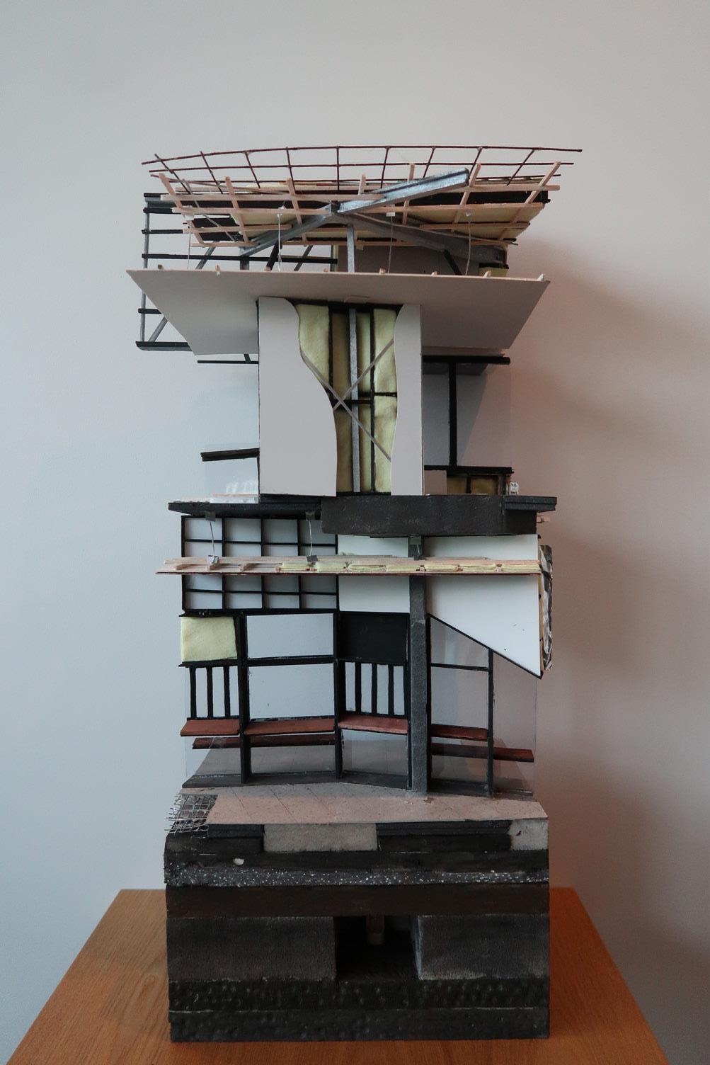
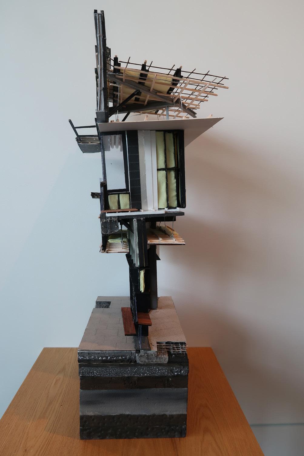
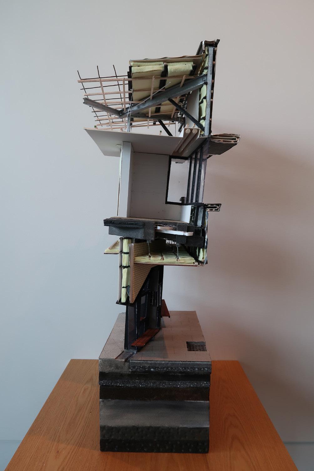
41
End.
https://issuu.com/moonyancheah25/docs/portfolio_moon_yan