Audio spectrogram visualizer using Raspberry pi
Overview
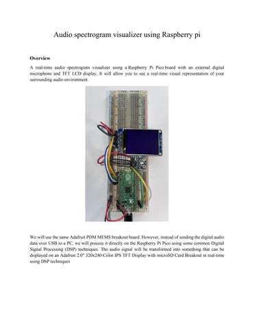
A real-time audio spectrogram visualizer using a Raspberry Pi Pico board with an external digital microphone and TFT LCD display. It will allow you to see a real-time visual representation of your surrounding audio environment.
We will use the same Adafruit PDM MEMS breakout board. However, instead of sending the digital audio data over USB to a PC, we will process it directly on the Raspberry Pi Pico using some common Digital Signal Processing (DSP) techniques. The audio signal will be transformed into something that can be displayed on an Adafruit 2.0" 320x240 Color IPS TFT Display with microSD Card Breakout in real-time using DSP techniques

Processing Pipeline
To create the spectrogram and display it on the LCD display in real-time the following steps will be needed:
1. Collect N audio samples from the digital microphone.
2. Apply a Hanning Window to the collected audio samples.
3. Run a Real Fast Fourier Transform (RFFT) with the input of the previous step.
4. Calculate the magnitude of the RFFT.
5. Map each RFFT magnitude to a color value to display on the LCD display.
6. Display the new row on the LCD.
7. Scroll to the new row and repeat.
If we choose an RFFT size of 256, we will have 128 useable magnitudes outputs to display on the screen, since this is less than the 240 pixels in each row of the display, we can display each row twice to maximize the visual real estate of the display.
For a faster visual response time, we can collect 64 new audio samples from the microphone at a time (instead of waiting for 256 new samples) and combine them with the previous latest 192 (= 25664) samples for each cycle. With a sample rate of 16 kHz, we will have 64 / 16, 000 seconds to perform all our calculations and update the display. This results in 4 milliseconds per iteration.
We will use the Microphone Library for Pico to capture data from the digital microphone. Arm's CMSISDSP library will be used to process the audio data in real-time. CMSIS-DSP is optimized for Arm CortexM processors including the Arm Cortex-M0+, which the Raspberry Pi Pico's RP2040 microcontroller (MCU) is based on. The ST7789 Library for Pico will be used to drive the output of the ST7789 TFT display
Hardware Setup
Solder male headers on to your Raspberry Pi Pico board, the Adafruit PDM MEMS Microphone Breakout board, and the 2" 320x240 Color IPS TFT Display with microSD Card Breakout board so they can be plugged into a breadboard.
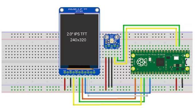
Once both items are soldered, place them on a breadboard and setup the wiring as follows:
Schematic View:
Wiring Setup:
Raspberry Pi Pico PDM Mic
Raspberry Pi Pico ST7789 3.3V 3V VIN VIN GND GND GND GND GND SEL GPIO18 SCK GPIO2 DAT GPIO19 MOSI GPIO3 CLK GPIO17 CS GPIO21 RST GPIO20 D/C
NOTE:
Setting up the Pico SDK development environment.
You'll first need to setup your computer with Raspberry Pi's Pico SDK and required toolchains
See the "Getting started with Raspberry Pi Pico" for more information
Getting
and compiling the pico-audio-spectrogram application
Make sure the PICO_SDK environment variable is set. export PICO_SDK_PATH=/path/to/pico-sdk In a VS Code write the code which is in the code section: Main.c Color map.h file CMakeLists.txt Pico SDK Import.cmake Create a build directory and change directories to it: mkdir build cd build Run cmake and make to compile: cmake .. -DPICO_BOARD=pico make Hold down the BOOTSEL button on the board, while plugging the board into your computer with a USB cable. Copy the audio_spectrogram.uf2 file to the mounted Raspberry Pi Pico boot ROM disk: cp -a audio_spectrogram.uf2 /Volumes/RPI-RP2/.
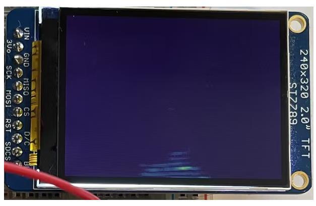
Testing it out
You can now try out various sounds, including speaking different words to see how they look in real-time on the spectrogram. Here is an example of what the speaking the word "yes" looks like on the display:
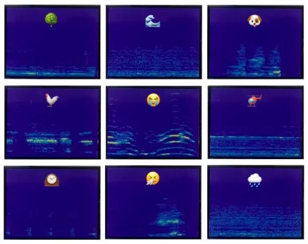 Examples for various sounds from the "ESC-50: Dataset for Environmental Sound Classification" can be found below:
for (int i = 0; i < (LCD_WIDTH / 2); i++) { // get the current FFT magnitude value q15_t magnitude = fft_mag_q15[i + FFT_BINS_SKIP]; // scale it between 0 to 255 to map, so we can map it to a color based on the color map int color_index = (magnitude / FFT_MAG_MAX) * 255; if (color_index > 255) { color_index = 255; } // cacluate the pixel color using the color map and color index uint16_t pixel = COLOR_MAP[color_index]; // set the pixel value for the next two rows row_pixels[LCD_WIDTH - 1 - (i * 2)] = pixel; row_pixels[LCD_WIDTH - 1 - (i * 2 + 1)] = pixel; } // update the cursor to the start of the current row st7789_set_cursor(0, row); // write the row value pixels st7789_write(row_pixels, sizeof(row_pixels)); // scroll to the new row st7789_vertical_scroll(row); // calculate the next row to update row = (row + 1) % LCD_HEIGHT; } return 0;
0x402a, 0x402b, 0x402b, 0x404b, 0x404b, 0x484b, 0x486b, 0x486c, 0x488c, 0x488c, 0x488c, 0x48ac, 0x48ac, 0x48ad, 0x48cd, 0x48cd, 0x48cd, 0x48ed, 0x48ed, 0x48ee, 0x490e, 0x490e, 0x490e,
0x492e, 0x492e, 0x492e, 0x494e, 0x494f, 0x494f, 0x494f, 0x496f, 0x496f, 0x496f, 0x498f, 0x498f, 0x498f, 0x41af, 0x41b0, 0x41b0, 0x41b0, 0x41d0, 0x41d0, 0x41d0, 0x41f0, 0x41f0, 0x41f0, 0x4210, 0x4210, 0x4210, 0x4210, 0x4230, 0x4230, 0x4231, 0x4251, 0x4251, 0x4251, 0x4251, 0x3a71, 0x3a71, 0x3a71, 0x3a91, 0x3a91, 0x3a91, 0x3a91, 0x3ab1, 0x3ab1, 0x3ab1, 0x3ab1,
0x3ad1, 0x3ad1, 0x3ad1, 0x3ad1, 0x3af1, 0x3af1, 0x32f1, 0x32f1, 0x3311, 0x3311, 0x3311, 0x3311, 0x3331, 0x3331, 0x3331, 0x3331, 0x3351, 0x3351, 0x3351, 0x3351, 0x3371, 0x3371, 0x3371, 0x3371, 0x3391, 0x2b91, 0x2b91, 0x2b91, 0x2bb1, 0x2bb1, 0x2bb1, 0x2bb1, 0x2bb1, 0x2bd1, 0x2bd1, 0x2bd1, 0x2bd1, 0x2bf1, 0x2bf1, 0x2bf1, 0x2bf1, 0x2c11, 0x2c11, 0x2c11, 0x2c11,
0x2c11, 0x2431, 0x2431, 0x2431, 0x2431, 0x2451, 0x2451, 0x2451, 0x2451, 0x2471, 0x2471, 0x2471, 0x2471, 0x2471, 0x2491, 0x2491, 0x2491, 0x2491, 0x24b1, 0x24b1, 0x24b1, 0x24b1, 0x24d1, 0x24d1, 0x24d1, 0x24d1, 0x24f1, 0x24f1, 0x24f1, 0x24f1, 0x24f1, 0x2510, 0x2510, 0x2510, 0x2510, 0x2530, 0x2530, 0x2530, 0x2530, 0x2530, 0x2550, 0x2550, 0x2550, 0x2d50, 0x2d70,
0x2d70, 0x2d70, 0x2d6f, 0x2d8f, 0x2d8f, 0x2d8f, 0x358f, 0x358f, 0x35af, 0x35af, 0x35af, 0x35af, 0x3daf, 0x3dce, 0x3dce, 0x3dce, 0x3dce, 0x45ee, 0x45ee, 0x45ee, 0x45ee, 0x45ee, 0x4e0d, 0x4e0d, 0x4e0d, 0x4e0d, 0x560d, 0x562d, 0x562d, 0x562c, 0x5e2c, 0x5e2c, 0x5e4c, 0x5e4c, 0x664c, 0x664c, 0x664b, 0x6e4b, 0x6e6b, 0x6e6b, 0x6e6b, 0x766b, 0x766a, 0x766a, 0x7e8a,
0x7e8a, 0x7e8a, 0x7e89, 0x8689, 0x8689, 0x86a9, 0x8ea9, 0x8ea9, 0x8ea8, 0x96a8, 0x96a8, 0x96a8, 0x96a8, 0x9ec7, 0x9ec7, 0x9ec7, 0xa6c7, 0xa6c7, 0xa6c6, 0xaec6, 0xaec6, 0xaee6, 0xb6e5, 0xb6e5, 0xb6e5, 0xbee5, 0xbee5, 0xbee4, 0xc6e4, 0xc6e4, 0xc6e4, 0xcee4, 0xcf04, 0xcf03, 0xd703, 0xd703, 0xd703, 0xdf03, 0xdf03, 0xdf03, 0xdf03, 0xe703, 0xe703, 0xe703, 0xef23,
endif () if (DEFINED ENV{PICO_SDK_FETCH_FROM_GIT} AND (NOT PICO_SDK_FETCH_FROM_GIT)) set(PICO_SDK_FETCH_FROM_GIT $ENV{PICO_SDK_FETCH_FROM_GIT}) message("Using PICO_SDK_FETCH_FROM_GIT from environment ('${PICO_SDK_FETCH_FROM_GIT}')") endif ()
if (DEFINED ENV{PICO_SDK_FETCH_FROM_GIT_PATH} AND (NOT PICO_SDK_FETCH_FROM_GIT_PATH)) set(PICO_SDK_FETCH_FROM_GIT_PATH $ENV{PICO_SDK_FETCH_FROM_GIT_PATH}) message("Using PICO_SDK_FETCH_FROM_GIT_PATH from environment ('${PICO_SDK_FETCH_FROM_GIT_PATH}')") endif ()
set(PICO_SDK_PATH "${PICO_SDK_PATH}" CACHE PATH "Path to the Raspberry Pi Pico SDK") set(PICO_SDK_FETCH_FROM_GIT "${PICO_SDK_FETCH_FROM_GIT}" CACHE BOOL "Set to ON to fetch copy of SDK from git if not otherwise locatable")
Conclusion
In this project you can use a Raspberry Pi Pico board with an external digital microphone and TFT LCD to createareal-timeaudiospectrogramvisualizer.Theprojectusesthe MicrophoneLibraryforPico tocapture 64 audio samples at a time from the microphone, then transforms the audio samples using Arm's CMSISDSP library into a spectrogram, which is then displayed on the TFT LCD display one row at a time using the ST7789 Library for Pico