

M OHAMMED AAKIF
A RCHITECTURE INTERN

ABOUT ME
The world of architecture has been a constant source of inspiration , and I am deeply passionate about every facet of this discipline. My approach to design is characterized by critical thinking, responsible decision-making, and a steadfast commitment to excellence.
In addition to my innate leadership qualities, I have an insatiable thirst for knowledge and an unwavering determination to expand my skillset. I am a quick learner, always eager to explore new horizons and push the boundaries of what is possible. My portfolio represents my unwavering commitment and skillfulness, displaying my works from my first four years of architectural education and demonstrating my exceptional creativity, passion, and dedication to thriving in this dynamic and exciting field
CONTACT
PHONE
+91 7829578647 (India)
+971 52 916 9469 (UAE)
EMAIL aakifmohammed769@gmail.com
2019_mohammed.a.l@wcfa.ac.in
ADDRESS
KHB Colony, Kalyanagiri, Mysore, Karnataka, India
Al Qusais Tower - Bu Haleeba, Al Qusais 1, Dubai, UAE
EDUCATION
WADIYAR CENTRE FOR ARCHITECTURE
2019 - 2024
UNDER GRADUATE DEGREE
President of WCFA, Student Council (2021-2022)
Head of the Advisory Board of WCFA, Student Council (2022-Present)
Member of Grievance Committee, WCFA (2022-Present )
Member of Special Cell for COVID19 Committee, WCFA (2022-Present)
Member of Anti Sexual Harrasment Committee, WCFA (2022-Present)
Participant of CP Kukreja Design Trophy, NASA (2022-2023)
Partcipant of The Design Board Competition (2022-2023)
Collaboration with Ingenious Concepts , Dubai (2021-2023)
SADVIDYA SEMI RESIDENTIAL PU COLLEGE
PRE UNIVERSITY
DOB 16th June 2001
LANGUAGE
English Urdu Hindi Kannada
SOCIAL MEDIA
Mohammed Aakif Lathif
Instagram mohammed.aakiff
2017 - 2019 11th - 12th Grade
DE PAUL PUBLIC SCHOOL SCHOOLING
2006 - 2016 1st - 10th grade School Leader (2015-2016)
SOFTWARE SKILLS OTHER SKILLS
AUTODESK AUTOCAD
AUTODESK REVIT
FUSION 360
SKETCHUP
RHINOCEROS 3D
ARCHICAD
ADOBE PHOTOSHOP
ADOBE INDESIGN
ADOBE ILLUSTRATOR
ADOBE PREMIER PRO
LUMION
ENSCAPE
VRAY ARC GIS PROCREATE
D5 RENDER GOOGLE EARTH
M OFFICE SUITE
Hand Model Making
Laser cutting
3D priniting
Sketching
Hand Drafting
Measure drawing and Documentation
Hands on Experience on wood and bamboo as a material
Layouts / Presentation
Diagramming & Analysis
ELECTIVES
Photography (Semester 03)
K J Pawan
Product Design (Semester 04)
Asst. Prof. Pallavi Dhomse
Digital Architecture (Semester 05)
Asst. Prof. Shashank
Cultural and Built Environment (Semester 06)
Asst. Prof. Shashank
Biomimicry (Semster 07)
Asst. Prof. Shashank
2
3 Sustainability Semester 07 Anegundi, Karnataka, India Semester 07 NASA 2022-2023 Interior Design Ingenious Concepts, Dubai Memorial Complex Semester 05 Co- Living Semester 04 Semester 04 & 05 01 02 03 04 05 06 07 INDUSTRIAL ARCHITECTURE CONTENT RELATED STUDY PROGRAM CP KUKREJA DESIGN TROPHY STUDENT HOUSING COLLABORATION WORKING DRAWINGS PUBLIC ARCHITECTURE
01.
INDUSTRIAL ARCHITECTURE SUSTAINABILITY

The intent of the studio was to provoke students to analyze, introspect and explore the process of design using various mediums. Through this process one establishes a more informed and aware sense of decision making. The studio focused on deducing inferences from observations through the act of contextual mapping. Further, the students were encouraged to develop intents from their studies, by making exploratory models. These models helped take positions, which further got translated into an architectural expression
Site Location : Anegundi, Karnataka
Site Area : 10000 sqm
Duration : 14 Weeks
4
Semester 07
Studio Guide : Prof. Shrutie Shah and Asst. Prof. Asijit Khan

“UN - HINGE”
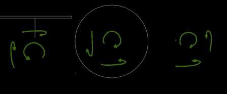
The exercise focused on understanding of mechanism of daily based products like gears, pulley, bottle cap and many more and considered the elements of the mechanism to be a component and can be replaced and can still be workable, which can be reflected in Sustainability approach where the built can be reused or the part can be replaced in many ways to sustain and to optimize.
Understanding of Mechanism
Gear Ratio : 60:1

Type : Compound gears
When the Smaller gear(12 teeth) is a driver, or on which the input is applied, which is connected to the bigger gear (60 teeth). the output will be 5X faster where as gets slower if the input is on the bigger gear

The Understanding from the First model
The RPM increase and decrease with respect to the size and the ration of the Gear
6
Gear 01 12(Teeths) Pitch Diameter = 30mm Gear 03 36(Teeths) Pitch Diameter = 90mm Gear 04 48(Teeths) Pitch Diameter = 120mm Gear 05 60(Teeths) Pitch Diameter = 150mm Main Shaft r=5 Clutch Shaft r = 5 Gear 01 12(Teeths) Pitch Diameter = 30mm Gear 01 12(Teeths) Pitch Diameter = 30mm Pitch Diameter Counter Shaft Supporting Wall Supporting Wall Gear 05 60(Teeths) Pitch Diameter = 150mm Gear 01 12(Teeths) Pitch Diameter = 30mm
Gear Ration : 1:60
Gears of single plane
The grids are all fixed in a single plane which just leads to the transmission in one plane
Gear Ration : 1:60
Gears of single plane
The grids are all fixed in a single plane which just leads to the transmission in one plane
Gear Ration : 1:60
Gears of single plane
The grids are all fixed in a single plane which just leads to the transmission in one plane
Gear Ration : 1:60
Gears of single plane


The grids are all fixed in a single plane which just leads to the transmission in one plane


Gear 05 60(Teeths) Pitch Diameter 150mm Gear 05 60(Teeths) Pitch Diameter 150mm Gear 05 60(Teeths) Pitch Diameter = 150mm Supporting Wall Counter Shaft 2.5 Main Shaft r=2.5 Clutch Shaft 2.5 Gear 05 60(Teeths) Pitch Diameter 150mm Gear 05 60(Teeths) Pitch Diameter = 150mm Gear 05 60(Teeths) Pitch Diameter = 150mm Supporting Wall Counter Shaft 2.5 Main Shaft r=2.5 Clutch Shaft Supporting Shaft = 2.5 Gear 02 24(Teeths) Pitch Diameter = 150mm Gear 02 24(Teeths) Pitch Diameter 150mm Shaft 02 r=2.5 Gear 05 60(Teeths) Pitch Diameter 150mm Gear 05 60(Teeths) Gear 05 60(Teeths) Pitch Diameter 150mm Supporting Wall Counter Shaft = 2.5 Main Shaft r=2.5 Clutch Shaft = 2.5 Supporting Shaft 2.5 Gear 02 24(Teeths) Gear 02 24(Teeths) Shaft 02 r=2.5 Shaft 03 Gear 05 60(Teeths) Pitch Diameter = 150mm Gear 05 60(Teeths) Pitch Diameter = 150mm Gear 05 60(Teeths) Pitch Diameter 150mm Supporting Wall Counter Shaft 2.5 Main Shaft r=2.5 Clutch Shaft = 2.5 Supporting Shaft 2.5 Gear 02 24(Teeths) Pitch Diameter = 150mm Gear 02 24(Teeths) Worm wheel Shaft 03 r=2.5 Worm Gear Counter Shaft = 2.5 Shaft 04
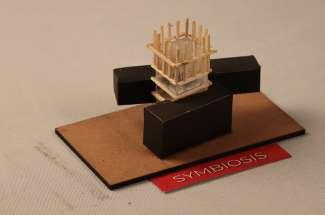
HOLISTIC INTENT MODELS
Holistic intent in architecture refers to an approach that considers the building and its surroundings as an interconnected whole. This approach recognizes the importance of sustainability, the use of natural materials, and the integration of nature into the design. This approach aims to create buildings that are not only aesthetically pleasing and functional but also contribute positively to the environment and the people who inhabit them.

The intent behind Dual roof was to provide protection from scorching sun of Anegundi as it works as an insulator and keeps the core structure cool
Walls can serve as an expression of aesthetic intent, reflecting the cultural, historical, or social context of a building and express the identity of its occupants, or to communicate a specific message or meaning.
The openings designed to let in natural light and are particularly effective at illuminating interior spaces without creating glare or over heating.
The intent aims to create the illusion that a building is floating above the ground which is primarily aesthetic, dramatization and functional benefits.
The intent aims to create the illusion that a building is floating above the ground which is primarily aesthetic, dramatization and functional benefits.
Walls can serve as an expression of aesthetic intent, reflecting the cultural, historical, or social context of a building and express the identity of its occupants, or to communicate a specific message or meaning.
This approach to building design seek to connect with nature and create healthier and more sustainable environments for people to live and work in.
The intent behind Dual roof was to provide protection from scorching sun of Anegundi as it works as an insulator and keeps the core structure cool
This architectural intent that involves the use of a rigid framework to support a building’s weight and distribute its loads and to relief the building from the ground


Membranes can be used as an architectural intent in many creative ways. They offer flexibility and versatility in design, making them an best option for a wide range of applications.


As an architectural intent, brise soleil can be used to improve the energy efficiency of a building by reducing the amount of solar heat gain that occurs in the interior spaces.
Symbiosis as an architectural intent refers to a design approach that seeks to create a mutually beneficial relationship between 2 build masses and its surrounding environment, to benefit the occupants
Walls can serve as an expression of aesthetic intent, reflecting the cultural, historical, or social context of a building and express the identity of its occupants, or to communicate a specific message or meaning.
Intent of a void is to create a sense of spaciousness and openness within a building. Voids can be used to break up the mass of a building and provide relief from the enclosed spaces.


The intent aims to create the illusion that a building is floating above the ground which is primarily aesthetic, dramatization and functional benefits.
As an architectural intent, brise soleil can be used to improve the energy efficiency of a building by reducing the amount of solar heat gain that occurs in the interior spaces.
9
FRAMES
MEMBRANE
BRISE SOLEIL SYMBIOSIS
BRISE SOLEIL LEVITATE VOID WALL
DUAL ROOF WALL EASY LIGHTS LEVITATE
DUAL ROOF BIOPHILIC WALLS/SYMBIOSIS LEVITATE
SECTIONAL MODELS
Exploration of sectional models is an essential exercise and provided a unique perspective on the spatial relationships and structural systems within a building.


10


11
ELEVATION MODELS
Exploration of Fenestration with the help of physical model of an elevation of the building, where the types of the skin and the windows were differed and get the understanding


12
FINAL MODEL

INDUSTRIAL BUILDING WITH SUSTAINABLE APPROACH
Sustainable architecture is a design approach that seeks to minimize the environmental impact of buildings while maximizing their energy efficiency. In the context of steel buildings, sustainable architecture often involves the use of passive cooling systems, which rely on natural means to regulate the temperature inside the building, as well as large spans to maximize usable floor space while minimizing the amount of material used.
A steel building with a large span allows for greater flexibility in terms of the layout and design of the interior space. The large span also provides more opportunities for natural light to enter the building, reducing the need for artificial lighting and increasing energy efficiency. When paired with passive cooling systems, such as operable windows and vents, the large span helps to promote natural ventilation, reducing the need for mechanical cooling systems.

14


15
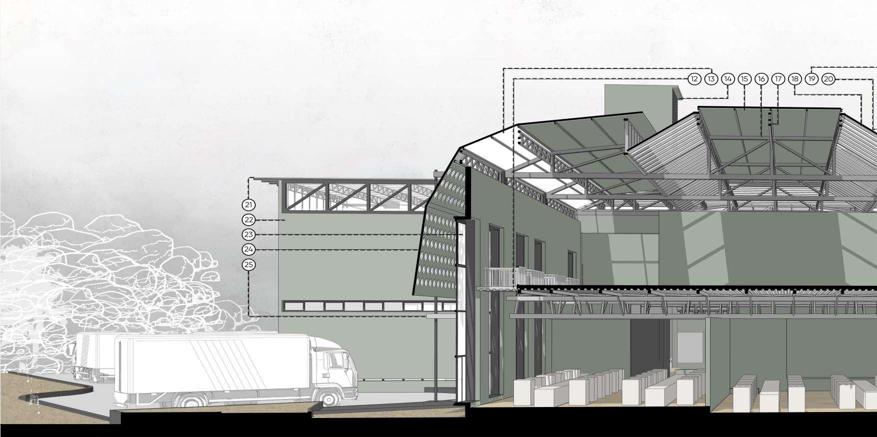
SECTIONAL ANALYSIS

The building’s section through the wind well, also known as a wind tower, reveals the natural flow of air. As wind enters the tower and passes beneath the floor, get cools with the water stored there. This cooled air then flows upward and circulates throughout the building, providing natural ventilation and cooling.
SPATIAL ORGANIZATION
Effective spatial organization depicted through pencil shading techniques,


01 Clear corrugated Roof 02 Primary Roof Truss 03 Wind Well (Wind Tower) 04 Skin (South Facing with smaller openings) 05 Frames a 06 Truss for the first floor 07 Large Windows (For better Natural light) 08 Washing Area 09 Column 10 Frames as Drying area 11 Pond for Cooling 12 Opening in the slab
Clear corrugated roof 14 Wind well 02 (Wind Tower) 15 Puff panels 16 Primary Roof Truss
Secondary Roof Truss 18 Clear Corrugated Roof 19 Wind Well
Air Vents
Clear corrugated Roof
The Wall
Large Windows (For better Natural light)
Skin (North facing with larger openings) 25 Anchored Column
13
17
20
21
22
23
24

The general Idea of the building’s orientation, volume, and form. These elements define the structure’s overall presence and relationship to the surrounding context, enabling to create a coherent and functional design. By carefully considering the massing, and also with the understanding of previous tasks help developing a strong foundation for the building’s design and construction. 03.


19
DIAGRAMS 01. 04. 02. 05. 06.

STRUCTURAL OVERVIEW
Cold Rolled Column
Space Provided Between two members of the column

Spacer
Metal Plates Welded and Bolted to the column
J Bolts
Bolt Holding the Column
Gusset Plate
Pedestal
Concrete Sandwich Wall
Insulation
Interior Concrete Wall
Bottom Plate (Locking Mechanism )
Slab
Bottom Plate Running Through
Column Member Space to Sandwich truss member
Bolted
Welded (Weld Joints)
L-Angles Provided to Hold the truss member in Place with stiffeners added

Second Column Member
Concrete Flooring (Decking Slab)
Aluminum Decking Sheet
Truss Beam ( @span of every 2m )
Aluminum Decking Sheet fixed with self drilling screw to the beam
Bracing of the truss
01 Driveway for Production unit 02 Public Plaza 03 Boulders in Plaza 04 Wind Well (Wind Tower) 05 Frames 06 Skin (North Facing with larger openings) 07 Large Windows (For better Natural light) 08 Purlins 09 Pile Foundation 10 Ground Floor (Raised Floor) 11 Box Section Members 12 Secondary Beams 13 Supporting Primary Member of Truss 14 Primary Tension Member 15 Bracings 16 Secondary Roof Truss 17 Major/ Primary Roof Truss 18 Clear Corrugated Roof 19 Clear Corrugated Roof 20 Wall Truss 21 Tertiary Roof Truss 22 Clear corrugated Roof 23 Major Roof Welded to Tension Column 24 Anchored Column 25 Truss For the First Floor 26 Column 27 Skin (South Facing with smaller openings) 28 Prefabricated Concrete Wall Section
BLOWN UP MODELS
Student housing in Mysore, India, is designed to provide students with a comfortable and convenient living experience while they study. These housing units typically include a variety of amenities to meet the needs of


02.
PUBLIC ARCHITECTURE MEMORIAL
Semester 05
Studio Guide : Asst. Prof. Asijit Khan
The studio focused on understanding the validity of abandoned architecture. The ways of deducing relations between the existing and the new. This would be further applied in deciphering the links between people, practices, architecture and the river. Analysis happened through the act of mapping, inferences were extracted via drawings and models. Further, students were encouraged to take positions; essentially conveying a design intent(s) using analysis.
Site Location : Srirangapathana, Karnataka
Site Area : 4000 sqm
Duration : 14 Weeks

25
1800s
The building was newly built and Different Forms of Built were coming together 1900s
The building was abandoned and was not in use. So the context started taking over slowly
MAPPING THROUGH MODEL
By mapping and comprehending the architectural features of ruins structures through models, i gained more in-depth understanding of the built environment, including its construction and past usage. Additionally, as time passes, the priorities and purpose of a building has changed.


Also Understanding of materials and techniques used during that time and how the deteriorated over time
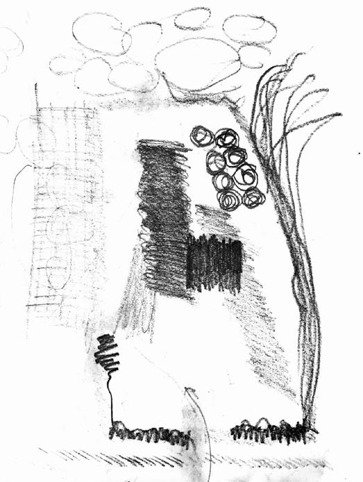
MAPPING THROUGH CHARCOAL SKETCHES
The exercise involved creating charcoal sketches of the spaces and elements of the ruins to comprehend the principles of architecture. This approach provided a brief overview of concepts such as rigidity, vistas, descending, levels, and enclosure, which subsequently served as the basis for the project’s objectives, and various intent models were approached.


26 Sectional View Section Focusing on descending 4 Columns (Interior) Section showing volume Sectional Model Ruins in different interval of time Main structure I`sland (Plinth)
ENCLOSURE

This architectural intent shows the placement of architectural elements provides an understanding of enclosure and its relationship with the overall architectural design.


APPROACHING WATER
The architectural intent focuses on the integration of the built environment and surrounding water, using the design to create a transitional space between land and water.
FRAME
The architectural intent highlights how architectural elements or the structure itself can serve as a frame to capture time, activities, nature, water, or any other built forms.
APPROACHING THE WATER (DESCENDING)
The architectural intent outlines a specific descending order towards the small water body as a means of facilitating a gradual transition towards it from all four sides of it.
APPROACHING THE WATER
The architectural intent outlines a specific descending order towards the large water body as a means of facilitating a gradual transition towards it.
LEVELS
The architectural intent emphasizes that incorporating various activities across different levels of a space can improve its overall quality.
FRAMING (MONUMENTAL)
The architectural intent highlights how architectural elements or the structure itself can serve as a frame to capture time, activities, nature, water, or any other built forms, which can be in a monumental scale.
BUILT RESPONSE TO WATER
The architectural intent explores how the built environment, or specific structures within it, can respond to different scales of water bodies, either by being constructed over them or in conjunction with them.
BUILT RESPONSE TO WATER
The architectural intent explores how the built environment, or specific structures within it, can respond to different scales of water bodies, either by being constructed over them or in conjunction with them.
BUILT RESPONSE TO WATER
The architectural intent explores how the built environment, or specific structures within it, can respond to different scales of water bodies, either by being constructed over them or in conjunction with them.
PLINTH MODULATION


The architectural intent investigates how the built environment or specific structures within it can adapt to different water body scales. This may include constructing over or adjacent to the water, as well as incorporating plinth modulation to facilitate various activities along the river.


BUILT RESPONSE TO WATER
The architectural intent explores how the built environment, or specific structures within it, can respond to different scales of water bodies, either by being constructed over them or in conjunction with them.
27
EXPLORING THE CURVE
The design approach was guided by specific intents that led to the use of curved forms, which were explored through charcoal sketches. This exercise facilitated a better understanding of the flow of curves and helped envision the necessary space or program, which was eventually integrated into the design. Additionally, the design was modified to accommodate the terrain of the site.

28


29
“PRAHR” MEMORIAL OF TIME
Named after the place, “Prahr, memorial of time” is a complex that was constructed with great respect for the history of the site and how it has evolved over the years, bearing witness to many experiences and emotions. The intent behind the design was to capture the journey of a 300-year-old building by framing it with a new structure that would convey the flow of time through its form, quality of space, and materials. Given its location alongside a river, the site has long been used for water burials, and this tradition continues to this day, with the complex serving as a place for this sacred activity.


30
.
A. The Wall
B. Island
C. Gallery Space
D. Reading Space
E. Space with Multiple function
F. Entry to Island through wall
G. Civic Amenities
H. Connection b/w Ruins and Memorial
I. Ruins

J. Bridge
K. Parking
L. Toilets
M. Amphitheater
N. Canteen
O. Tertiary wall
P. Secondary wall
31
A. Toilets
B. Amphitheater

C. The Wall
D. Niches in The Wall
E. Civic Amenities
F. Space within The Wall
G. Gallery/Reading/Meditation Space
H. Ruins
I. Island
A. Amphitheater

B. Niches in The Wall
C. Civic Amenities
D. Ruins
E. Entry to Island through The Wall
F. The Wall
G. Ruins
H. Entry to Island through Ruins
32

33
STUDENT HOUSING CO-LIVING

05
Co-living the new way of intervening the Community.
• A catalyst for the lost social interactions
in community
• Socio cultural integration with measures like recycling, low energy use, energy harvesting, water conservation, waste management and urban farming etc…
• Requirement is open for individual interpretation (The Co living can be for Students aged between 17 to 22 or techies between 25 to 35)
• Setbacks/Rules as mentioned to be taken in account
Site Location : Mysore, Karnataka
Site Area : 4000 sqm
Duration : 14 Weeks
34
03.
Semester
Studio Guide : Prof. Anand Chalawadi and Asst. Prof. Akash Rai


35
ABSTRACTING AND ANALYZING ONE’S NEIGHBOURHOOD AND THE UNIT


Abstracting and analyzing one’s neighborhood and the unit refers to the process of carefully observing, understanding, and evaluating the physical, social, and cultural characteristics of both the larger community and the specific living unit within it. This process can be done for various reasons, such as for personal reflection, for urban planning purposes, or for architectural design.


Social characteristics
Physical characteristics
Economic characteristics
By abstracting and analyzing both the neighborhood and the unit, it becomes possible to gain a deeper understanding of the relationships between the physical, social, and cultural factors that shape our living environments. This knowledge can be used to make informed decisions about urban planning, architectural design, and personal reflection, and can help to create more livable and sustainable communities.
36
THE STREET VIEW


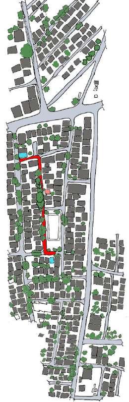

MOSQUE COMERCIAL BUILDINGS TEMPLE MY HOME SHOP I VISIT BANK ROAD
RESIDENTIAL BUILDINGS


MOSQUE VISIT 5 TIMES A DAY


Shop 1 : grocery items
SHOP

BANK Visit frequently (bank/atm)


Mosques were close by And more people from My community Stayed here like a family
Shop 2 : friends mobile store (Spending My free time)
BUILDINGS
37 N
N N
N
N
SCHOOL RESIDENTIAL
MY HOME ROAD VEGETATION
N
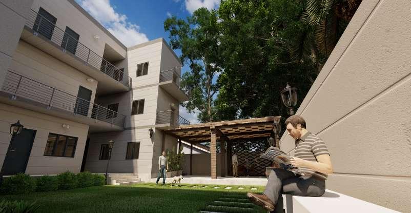
STUDENT HOUSING


Student housing in Mysore, India, is designed to provide students with a comfortable and convenient living experience while they study. These housing units typically include a variety of amenities to meet the needs of students, including comfortable bedrooms, shared common areas, and study spaces.
One of the key features of student housing in Mysore is the emphasis on social connectivity. Many student housing units are designed to foster a sense of community among residents, through the creation of shared spaces, such as lounges, kitchens, and recreational areas. These spaces encourage students to interact with one another, building relationships and forming a support network that can help to enrich their overall university experience.
In addition to these amenities, student housing in Mysore also often includes architectural surprise elements that are designed to enhance the overall living experience of students. These elements can range from innovative design features, such as green roofs and walls, to interactive and creative spaces, such as art studios and music rooms. These surprises add a unique and exciting dimension to the housing units, providing students with opportunities to explore their creative and artistic side, while also helping to foster a sense of community and connection.
Overall, student housing in Mysore is designed with the needs and interests of students in mind. By providing a range of amenities and social spaces, as well as unique architectural elements, these housing units help to create a supportive and engaging environment for students to live and learn.
38

39

40
ISOMETRIC VIEW OF HOUSING

41
04.
WORKING DRAWINGS
HOUSING PROJECT
Semester 05 / 06
Studio Guide : Prof. SG Srinivas
During the semester, the studio prioritized the acquisition of knowledge and skills related to producing Working Drawings for housing projects. Meanwhile, our specific studio group dedicated our efforts to elaborating on the plans required for approval and honed in on details such as windows, toilets, kitchens, and doors. The drawings we completed throughout the semester reflect these endeavors.
4th Sem, STUDENT HOUSING, Mysore
GROUND FLOOR, PLAN 01 LVL+3650
42
PEDESTRAIN 1000x2100 900x2100 700x2100 1200x2000 900x500 NOMENCLATURE D1 D2 D3 W2 W3 MAIN DOOR BEDROOM DOOR BATHROOM DOOR BEDROOM WINDOW BATHROOM VENTILATOR 2100 2100 2100 2100 2100 NAMES DIMENSIONS LINTEL HEIGHT 3600x2100 D5 BALCONY DOOR 2100 SHEET NO: SHEET SIZE: PROJECT NO: DRAWING NO: SCALE: UNIT: TEAM: COLLEGE NAME: PROJECT NAME: DRAWING TITLE: DRAWN BY: GENRAL NOTES: KEY PLAN: CHECKED BY: DATE:
MD AAKIF PRAJWAL 12/06/2022
WCFA WADIYAR CENTRE FOR ARCHITECTURE No. 1011, CH20, Krishnaraja Boulevard, Chamaraja Mohalla, K.G Koppal, Mysuru, Karnataka 570005. Contact No: 0821 XXXXXX Email: XXXXXXXXXXXXXXX MD AAKIF 4CM19AT042 PRANAV KS 4CM19AT052 PRAJWAL BB 4CM19AT051 M RISHI 4CM19AT036 01 A3 01P01 01 1:100 MM SIGN: SIGN: N BALCONY 1286 3885 LIVING ROOM 6486 3885 BEDROOM 1 5828 X 3828 BEDROOM 2 5828 X 3830 TOILET 1828 X 2613 TOILET 1827 X 2715 DUCT DUCT KITCHEN 2093 x 1200 D2 D2 D1 D5 D3 D3 W3 W3 W2 W2 KITCHEN BALCONY LIVING ROOM TOILET BEDROOM 2 TOILET 1286 x 3828 6486 x 3828 1827 x 1285 1827 x 2600 5828 X 3827 1827 X 2612 DUCT BEDROOM 1 4212 X 3885 W2 W2 D2 D2 D1 D3 D3 W3 W3 D4 BALCONY 1286 x 3885 LIVING ROOM 6486 x 3885 BEDROOM 1 5828 X 3828 BEDROOM 2 5828 X 3830 TOILET 1828 X 2613 TOILET 1827 X 2715 DUCT DUCT KITCHEN 2093 x 1200 W2 W2 D2 D2 D1 D5 D3 D3 W3 W3 CORRIDOR CORRIDOR 1 2 3 4 5 6 7 8 9 10 11 12 13 UP +150 UP 0.A.2 0.A.1 0.A.4 +2150 +150 9 10 11 12 13 14 8 8' 2000 4000 4000 4000 4000 4000 4000 A B C E F D 6000 6200 2000 2000 4000 D7 D7 D7 D7 D7 KITCHEN BALCONY LIVING ROOM TOILET BEDROOM 2 TOILET 3828 x 1286 3828 x 6486 1285 x1827 2600 x 1827 3827 5828 2612 x 1827 DUCT BEDROOM 1 3885 x 4212 W2 W2 D2 D2 D3 D3 W3 W3 D1 D5 KITCHEN BALCONY LIVING ROOM TOILET BEDROOM 2 TOILET 1286 x 3828 6486 x 3828 1827 x 1285 1827 2600 5828 X 3827 1827 X 2612 DUCT BEDROOM 1 4212 X 3885 W2 W2 D2 D2 D1 D3 D3 D4 W3 W3 CORRIDOR CORRIDOR CORRIDOR CORRIDOR 4 5 6 7 8 9 10 11 12 13 14 +150 DINNING UP UP 0.A.3 0.B.1 +2150 +2150 D1 W2 W2 W2 W2 W2 W2 KITCHEN 1 3 5 4 2 6 7 8 8' A B C E F D G' G 6000 6200 4000 4000 4000 6000 4200 2000 2000 4000 2000 2000 255 255 5770 X 3985 D7 D7
43 1 W4 TERRACE SECOND FLOOR FIRST FLOOR GROUND FLOOR +2150 +5300 +8450 +11600 SITE LEVEL +150 ROAD LEVEL 0 3000 3000 3000 3000 PCC BED AGGREGATE FOOTING BASMENT WINDOW RETAINING WALL COMPOUND WALL WINDOW SILL EXTENDED SILL INFILL FOR THE PROJECTION DRIP MOULD PROJECTION FROM LINTEL LINTEL INFILL FOR PROJECTION COPING PARAPET WALL WEATHER PROOFING COPING DRIP MOULD WINDOW 02 BEAM 450X230mm EXTERIOR PLASTER 20mm INTERIOR PLASTER 10mm FLOORING 10mm PEDESTAL BASEMENT LEVEL -1000 WEATHER PROOFING BALCONY 3885 x 1286 LIVING ROOM 3885 x 6486 BEDROOM 1 3828 x 5828 BEDROOM 2 3830 x 5828 TOILET 1828 X 2613 TOILET 2715 x1827 DUCT DUCT D2 D2 D5 W2 W2 D3 D3 D1 W3 W3 KITCHEN BALCONY LIVING ROOM TOILET BEDROOM 2 TOILET 3828 x 1286 3828 x 6486 1827 x 1285 2600 x1827 3827 x 5828 2612 x1827 DUCT BEDROOM 1 3885 4212 D2 D2 D5 W2 W2 D3 D3 D1 W3 W3 BALCONY 3885 x 1286 LIVING ROOM 3885 x 6486 BEDROOM 1 3828 5828 BEDROOM 2 3830 5828 TOILET TOILET DUCT KITCHEN 2093 x 1200 W2 W2 D2 D2 D1 D5 D3 D3 W3 W3 CORRIDOR 0.B.2 0.B.3 0.B.4 KITCHEN 1200 1000 DUCT +2150 +2150 +150 J K L M N H G' 4000 4000 4000 4000 4000 4000 1 3 5 4 2 6 7 2000 4000 2000 2000 4200 6000 2670 x 1885 2670 x 1885 D7 D7 D7 D7 D7 2900 2000 1500 1200 150 450 2100 450 450 2900 1990 300 122 450 250 670 300 OUTSIDE INSIDE PROJECTION OF 300mm WINDOW 02 EXTERIOR PLASTER 20mm PROJECTION OF 300mm INTERIOR PLASTER 10mm SLIDING WINDOW 02
44 4000 2000 355 575 K 780 200 800 D7 J 4 5 900 1200 600 900 900 2700 775 250 480 346 700 380 450 450 1885 150 600 GLASS PARTITION BATHROOM SHELVES WASH BASIN WALL SHELF LEDGE WALL SOIL WATER GREY WATER COLD WATER HOT WATER SHOWER AREA SEAT VENTILATOR W3 D3 TOILET PLAN SCALE : 1:20 4000 K J W3 D3 450 776 778 300 25 2100 781 150 2100 DOOR PARTITION GLASS SHOWER AREA SHELF SHOWER AREA SEAT 650 1200 ONE TILE DROP TOWARDS SHOWER AREA SHOWER AREA C SECTIONAL ELEVATION SCALE : 1:20 1200 4000 355 350 50 925 2200 2700 WC MI 400 625 900 890 480 147 850 600 890 2100 1850 K J WASH BASIN CABINET WASH BASIN WASH BASIN WALL SHELF CINDER BLOCK FILLING SHOWER AREA SHOWER AREA WALL SHELF GLASS PARTITION W3 300 150 D7 A SECTIONAL ELEVATION SCALE : 1:20 5 4 2000 150 450 700 725 1700 275 2100 1200 LEDGE WALL GLASS PARTITION SHOWER AREA 5 4 2000 400 50 703 147 1200 1200 600 150 450 WC B SECTIONAL ELEVATION SCALE : 1:20 D SECTIONAL ELEVATION SCALE : 1:20


45 BASIN CABINET BASIN MIRROR BLOCK FILLING BASIN WALL SHELF LEDGE WALL DOUBLE DOOR FRIDGE UPPER CABINETS EXHAUST HOOD SINK(1B1D) BACK SPLASH MIXER HOB (HOT PLATE/GAS) A B 1 1 A B KITCHEN PLAN +1000mm from FFL 1:25 BREAKFAST COUNTER COUNTERTOP SINK(1B1D) MIXER FRONT DOOR WASHING MACHINE CUPBOARD HANGING LIGHTS STOOL D1 W2 W2 DUCT UTILITY KITCHEN 2500 600 300 600 600 400 860 800 2100 2500 1000 2120 3420 3500 3450 A B A B DOUBLE DOOR FRIDGE COUNTERTOP BACK SPLASH BACK SPLASH MIXER UPPER CABINETS SINK(1B1D) SKIRTING SKIRTING DUCT DOOR MIXER SINK(1B1D) FFL W2 W2 DRAWER DRAWER DRAWER DRAWER DRAWER DRAWER DRAWER DRAWER DRAWER DRAWER DRAWER DRAWER DRAWER D1 600 70 2500 850 100 2100 850 100 1 A EXHAUST HOOD BREAKFAST COUNTER STOOL HANGING LIGHTS COUNTERTOP UPPER CABINETS LED STRIP LIGHT DOUBLE DOOR FRIDGE LEGS SKIRTING LEGS SKIRTING FFL 1050 200 850 100 100 850 600 320 300 600 200 500 SECTION D 1:25 1 1 EXHAUST HOOD BREAKFAST COUNTER STOOL HANGING LIGHTS UTILITY DOOR UPPER CABINETS LED STRIP LIGHT MIXER COUNTERTOP LEGS SKIRTING LEGS SKIRTING FFL D1 850 100 600 600 200 1050 100 2100 200 710 500 300 600 300 320 SECTION B 1:25 1 A B DOUBLE DOOR FRIDGE COUNTERTOP BACK SPLASH STOOL UPPER CABINETS BREAKFAST COUNTER WASHING MACHINE CUPBOARD HANGING LIGHTS EXHAUST HOOD 1050 600 70 200 B SECTION E 1:25 A B A B WASHING MACHINE CUPBOARD BREAKFAST COUNTER COUNTERTOP HANGING LIGHTS EXHAUST HOOD SKIRTING FILLER H.O.B BEAM D1 1050 850 100 200 2100 900 SECTION C 1:25
RELATIVE STUDY PROGRAM


A study program was conducted to investigate and record the town of Anegundi in Karnataka, along with the

THE HOUSE
An ancient residential typology is followed where in a veranda opens out into the streets supported by an intricate colonnade carved out of wood. As one enters there’s a skylight that is essential for lighting up the private spaces.


The house has a beautiful quality with a centrally located water harvesting system from which the household is run. An ancient residential typology is followed where in a veranda opens out into the streets supported by an intricate colonnade carved out of wood. As one enters there’s a skylight that is essential for lighting up the private spaces. The house has a beautiful quality with a centrally located water harvesting system from which the household is run.

46 Semester 07 | GROUP WORK Section
Plan
Exploded
ancient heritage houses and the town’s typology.
05.
CP KUKREJA DESIGN TROPHY
NASA 2022-2023

One such example of a historical place would be The Amba Vilas palace, an incredible man-made edifice in the heritage city of Mysore, Karnataka. A palatial structure that tells many tales of the region’s complex and intriguing past. It has been 75 years since independence and reminiscing about the past, where people had to fight with their lives at stake to free India, today, if we were to plow about what independence means to us, the answers would vary from each other and also from the ideas in the past. Marking these changes in thoughts, culture, advancements in technology, health & wealth we celebrate the 75th year of independence as the ‘Diamond Jubilee’. Diamond represents strength, wealth and effulgence similar to the aspects of the royal symbol ‘GajaLakshmi’ cited above the central arch of the Mysore palace.
We intend to create a setting that would integrate the idea of strength from diamond (75th year of independence) and elephants of GajaLakshmi along with abstractions extracted from the diamond’s anatomy. Diamond gets is strength from its c-c hexagonal bonds which forms a stable geometry. Each molecule of diamond consists of 38 nodes and 40 lattices. Hence taking forth this study we integrated the 2d-diagrams with 38 nodes forming a space affiliating our intend.


47 06.
AMBA VISTA
07. COLLABORATION
Ingenious Concepts, Dubai
META HOMES
Location : Sol Bay, Dubai
Status : Completed
Company : Ingenious Concepts

Client : Meta homes
This was a collaborative project involving the design and 3D visualization of the interior space of a newly established company, META HOMES, located in Dubai. META HOMES is a real estate company that is managed by two partners. The project involved designing two director rooms, a meeting room, an office manager’s space, seating for staff, and an informal pantry area. The project was completed with assistance from INGENIOUS CONCEPTS, a company based in Dubai, and provided valuable insights into space planning, material selection, and attention to detail. Most importantly, the team took great care to understand the client’s needs and requirements, delivering the best possible outcome for their specific needs.


48
Location : Jafza, Dubai
Status : Design only
Company : Ingenious Concepts


Client : AquaChemie
This project was yet another collaboration, focusing solely on designing alternative options for AQUACHEMIE, a client whose original design was created by a different firm. The project’s primary objective was to explore different designs using the same materials, refining the luxurious interior design, and ensuring that the client’s requirements were fully met. INGENIOUS CONCEPTS, Dubai, provided invaluable assistance throughout the project


49
