ACADEMIC PORTFOLIO
My Khanh Vo
MSc General Structural Engineering
Imperial College London, UK
2015-2022

My Khanh Vo
MSc General Structural Engineering
Imperial College London, UK
2015-2022
A selection of projects presented within this section belongs to:
Department of Civil and Environmental Engineering - Imperial College London
Department of Civil and Structural Engineering - University of Sheffield
ICS Design Team - Simpson Strong-Tie Vietnam Company Limited
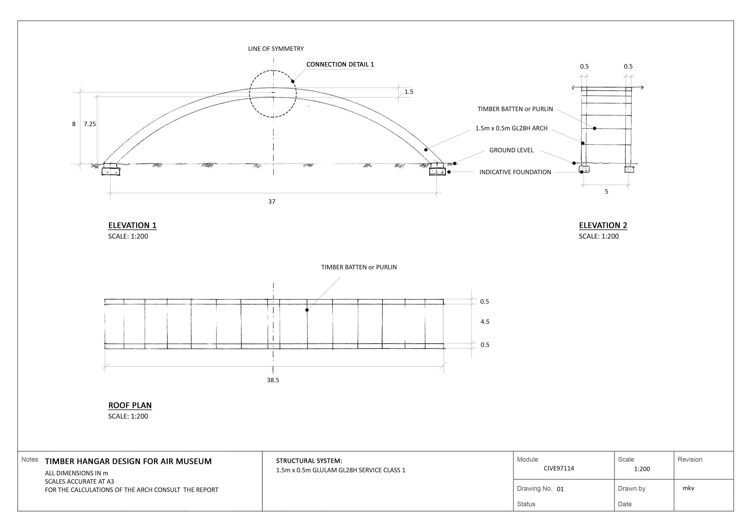
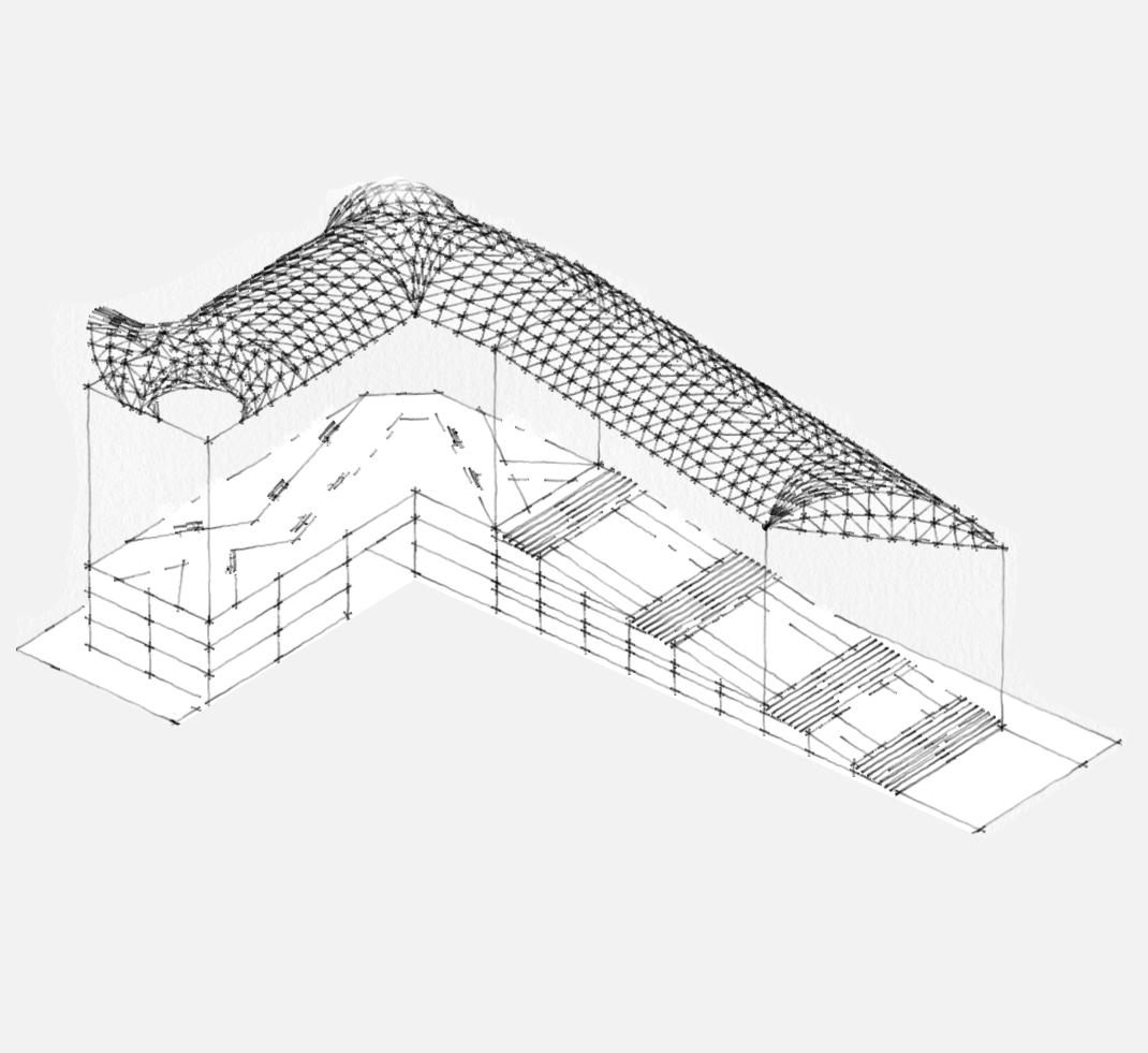
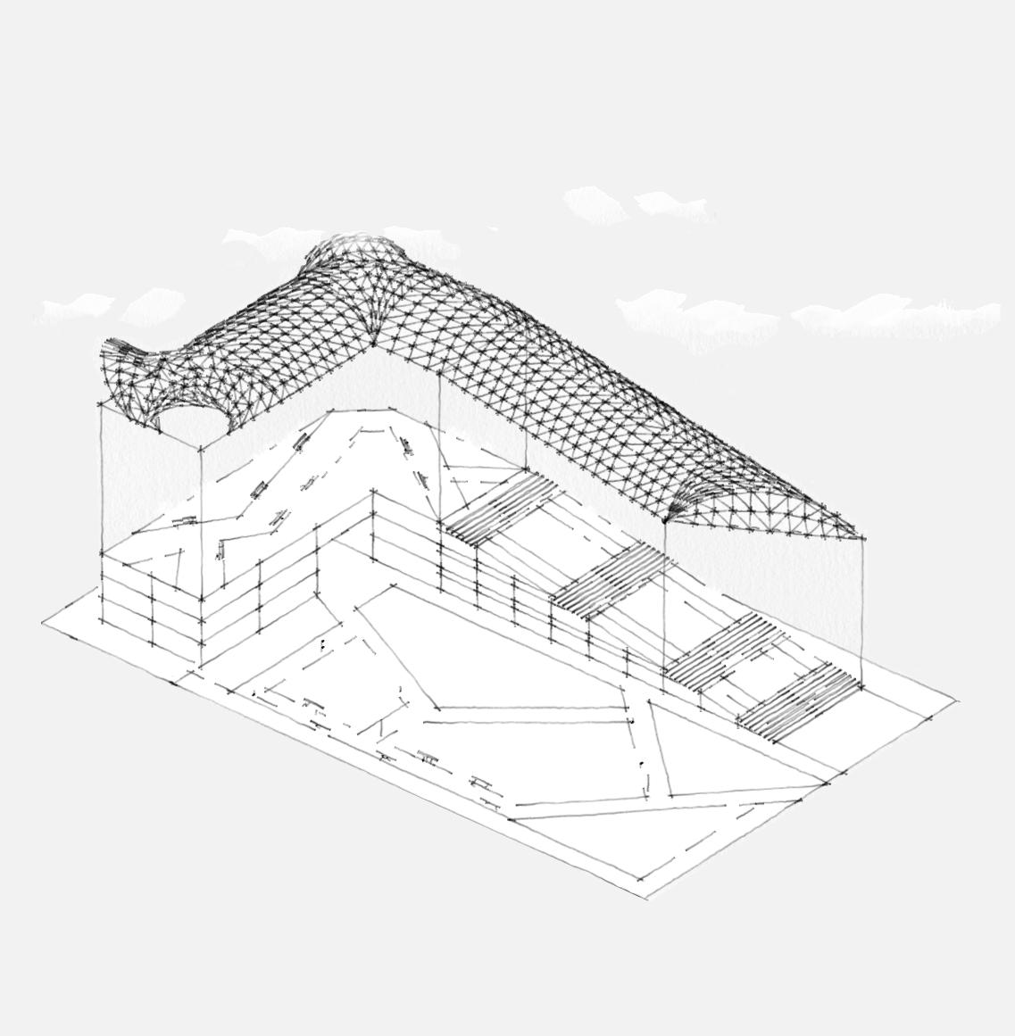
TIMBER COURSEWORK | CIVE97114
Group project
November - December 2020
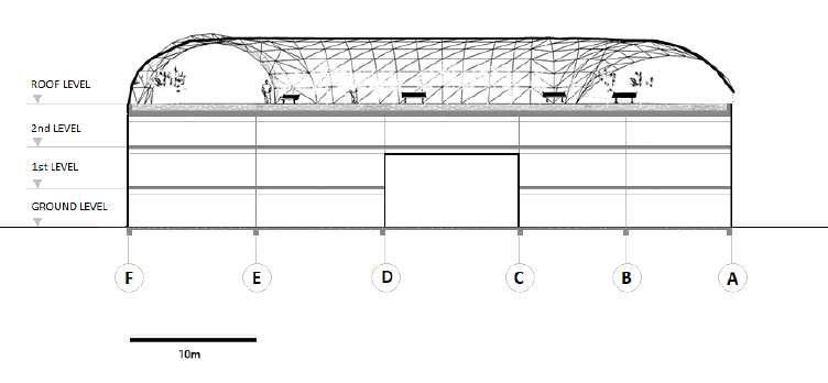
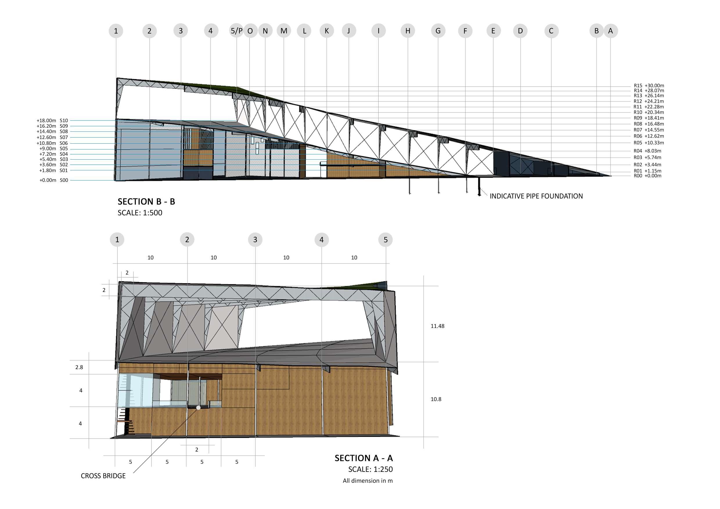
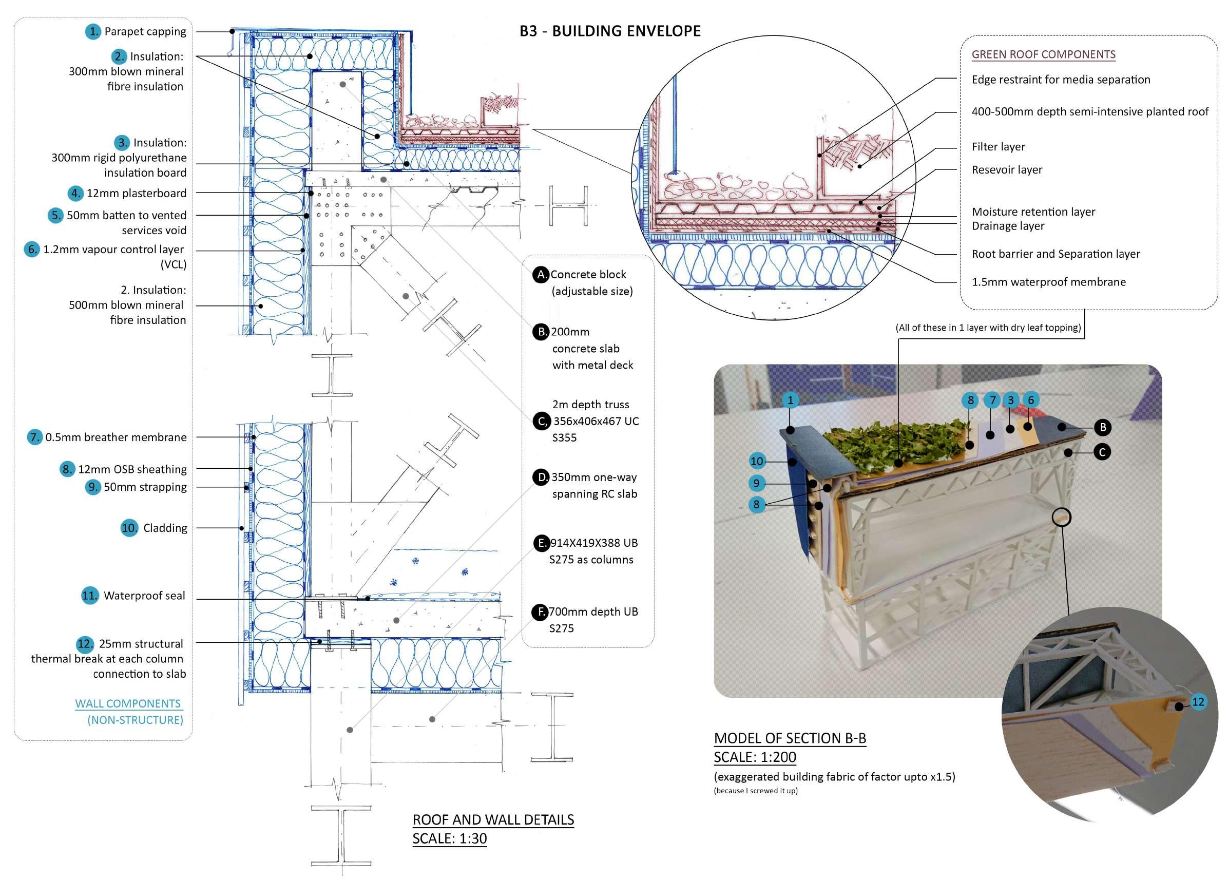
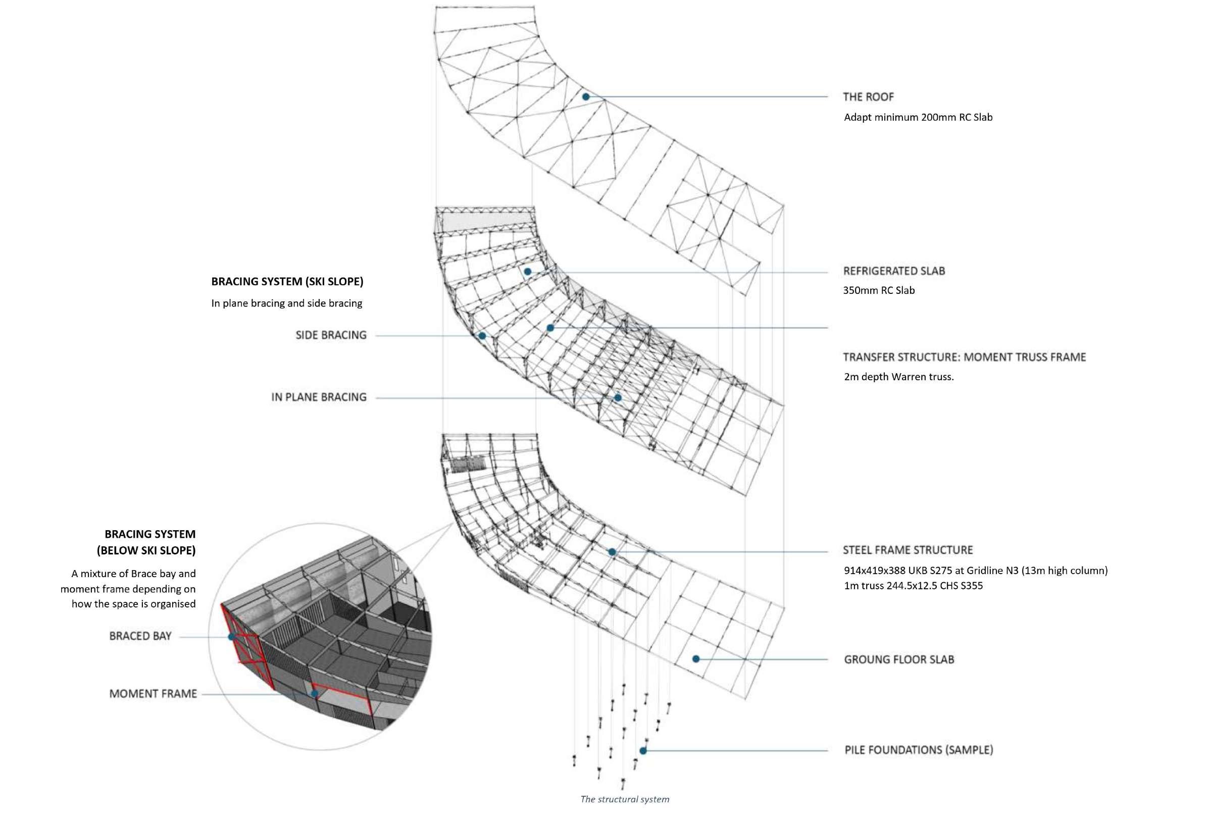
Timber hangar design - A4 Drawings.
SHELL BUCKLING COURSEWORK | CIVE97113
Individual project
April - May 2022
Analysis sequence in accordance with EN1993-1-6 code of practice for a cylindrical shell subjected to buckling load using Abaqus CAE.
STRUCTURAL FIRE ENGINEERING COURSEWORK | CIVE97115
Individual project
April - May 2022
Parametric temperature-time curves from standard results generated in accordance with EN1993-1-2 code of practice and computational simulation of Abaqus for steel beam element with and without protection in a room unit, and deflection behaviour of steel frame unit consisting of that beam element.
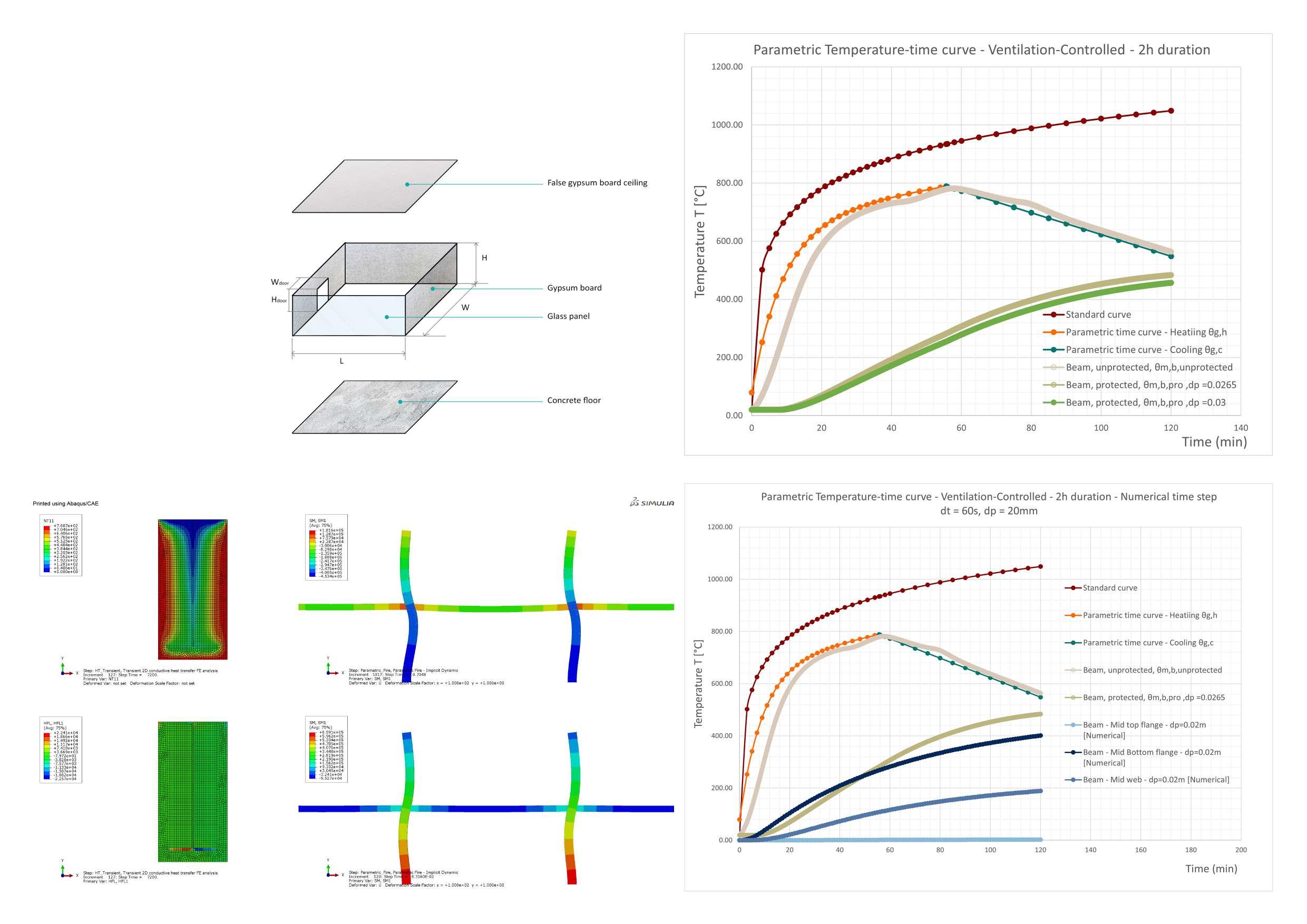
Given a room unit with given material properties to perform analysis of a beam element with and without protection layer, and determine the required thickness of the cover to ensure performance in 2-hour duration fire before failure. FE verification of the beam is performed with ABAQUS 2D planar deformable shell element with transient heat transfer mode. NT11 is temperature domain code. HFL is Heat flux magnitude code.
Sub-frame level and building cross-section level of analysis were also performed but mainly for the inspection of deformation behaviour.
Buckling investigation of a axisymmetric cylindrical tank under 2 load cases and number of types of shell analysis in accordance with EN1993-1-6 guidance, boundary conditions of one clamped edge and one pin ended, with and without imperfection. Imperfection in the form of first buckling eigenmode LBA using mesh perturbation method, and a localised weld depression. Load case 1 includes uniform internal pressure and roof load, performed LA only. Load case 2 of roof load only is used for a range of analyses as shown.

Group Project - A0 drawings
June - August 2021
Copyright of work produced belong to Imperial College London
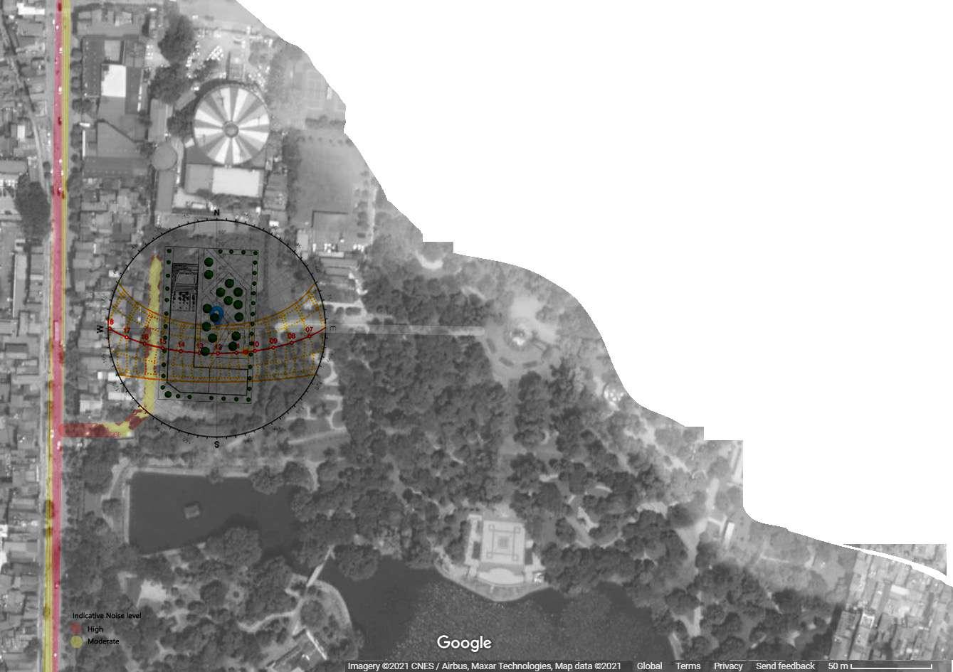
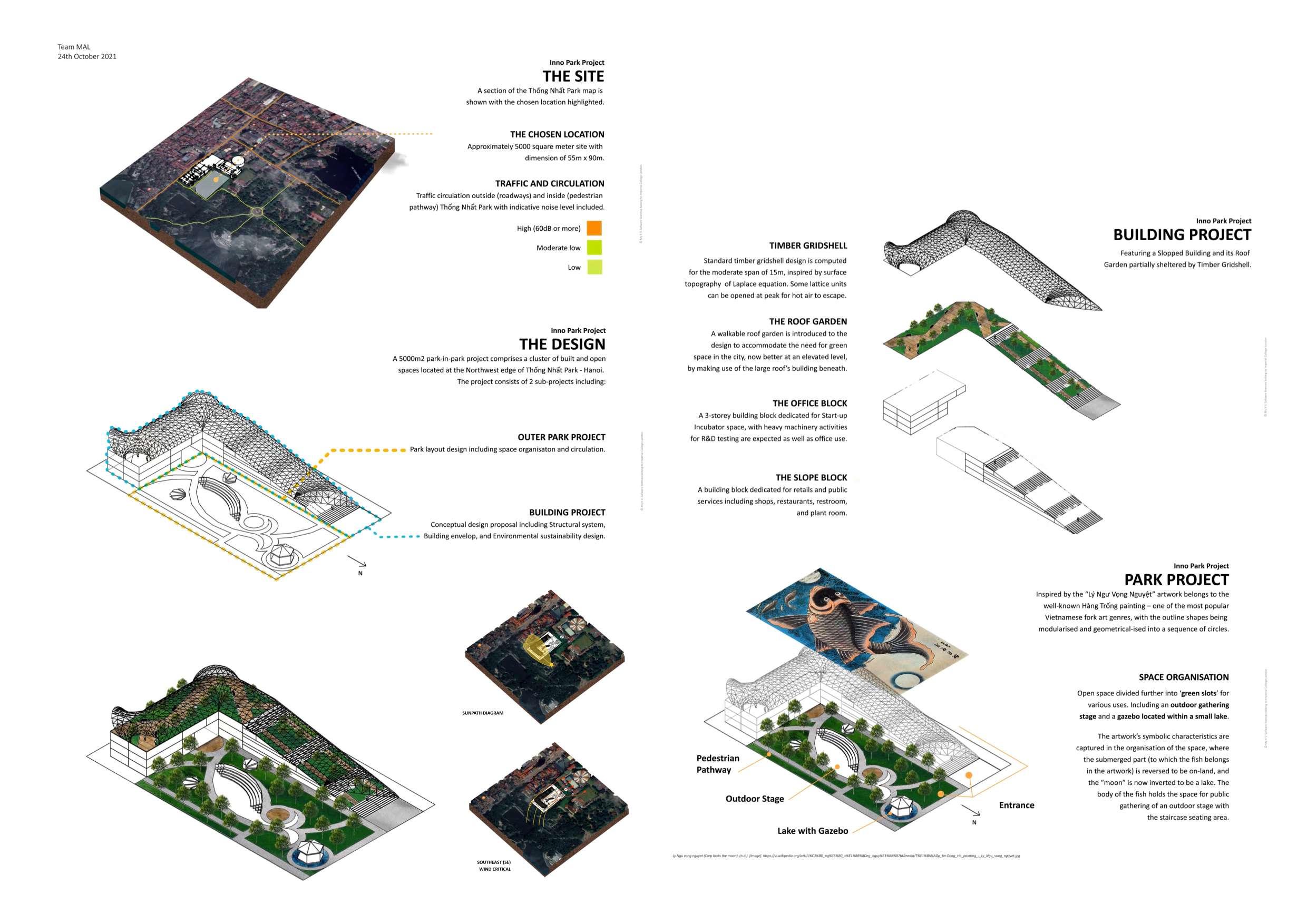
Competition for the redesign of Thống Nhất Park – Hanoi, Vietnam with the requirements of a complex shelter and a park in park concept. Been to the final and achieved one of the 5 best design proposals award. The competition was aired in one of the channels of the national television broadcaster of Vietnam (VTV).
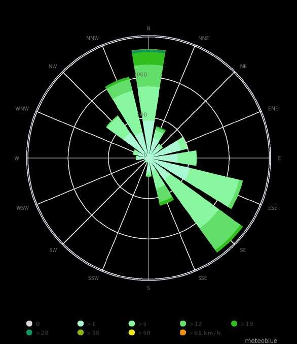
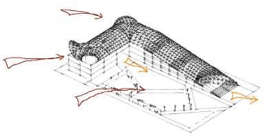
Wind rose: 2 main strong wind directions are North and Southeast. The site is surrounded by nearby high-rise buildings and trees, thus actual wind speed and pressure can be lower.
Noise map: Moderate level of noise pollution. Data is indicative
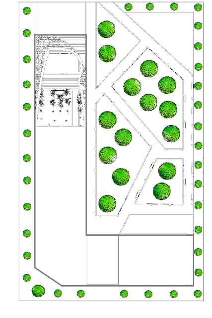
A 5000m2 park-in-park project comprises a cluster of built and open spaces located at the Northwest edge of Thống Nhất Park - Hanoi.
Target audiences: The young, nearby residents, children, and pets.
Location: Slot 3 – an indeterminate purpose’s space located at the edge of the Thống Nhất park.
Typical social and cultural activities expected from different target audience groups to perform at the park including:
• Sport space - nearby badminton and roller-skating spots should take care of the audience of this group.
• Meet up space. Activities expected: Walking and light exercise, taking pictures, book reading, social interactions.
• Entertainment and cultural exhibition space.
Weather and microclimate:
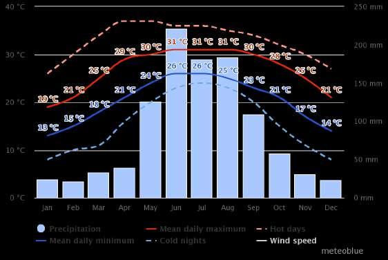
Ê Seasons, temperature, and humidity: Tropical climate, 4 seasons with average summer temperature of 31° and winter of 14°. High level of humidity. The design needs to accommodate both ventilation & the cooling system in summer, and insulation and thermal comfort in winter.
Ê Average sunshine hour: Around 11 hours in winter and up to 13 hours in summer. However, most of the time the condition is partly cloudy and overcast - investment for solar panel may not be beneficial.
Ê Shadowing (favour): Like wind, nearby buildings and trees may provide shadowing to the site. Further site investigation needed.
Ê Air quality: Moderate to high level of air pollution within the city identified, with main pollutant of PM2.5. Direct external exposure is unfavourable.
Others:
Ê Historical use of site: Exist 2-storey foundation at the site from an abandoned construction. The information provided gives a concern that local residents around site opposed to the idea of any permanent construction at that specific location (slot 3).
Ê Transportation and circulation: Ease of access to the park from Lê Duẫn street for visitors and retail supplies. Acts as a Northwest gate to enter the mother’s park.
MEET THE TEAM
Nguyễn Huy Lân Imperial College London | UK
MEng Civil Engineering
Chu Thị Lan Anh State University of Land use Planning | Russia
MSc Landscape Architecture
Võ Khánh My Imperial College London | UK
MSc General Structural Engineering
Precipitation: High level of precipitation. With the annual precipitation of 1700mm, higher than the world average of 1000mm, rainwater and stormwater harvesting system is potential.
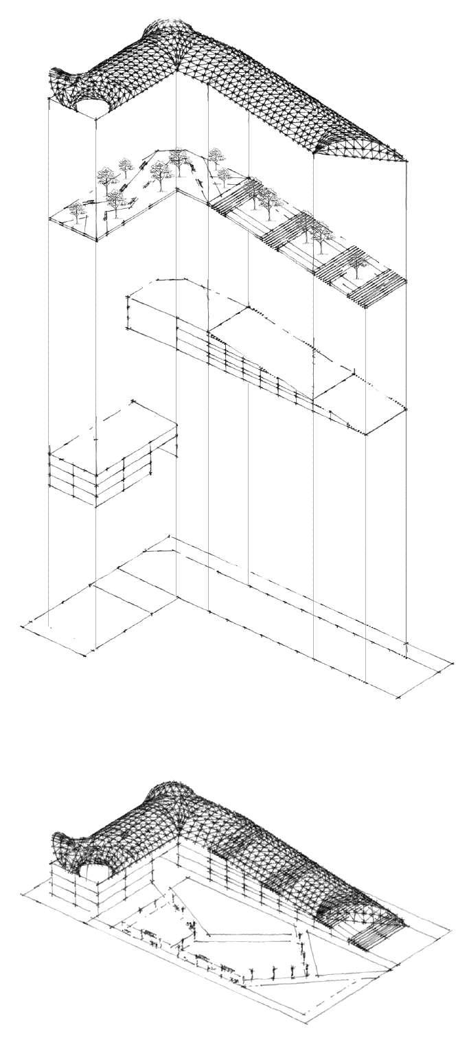
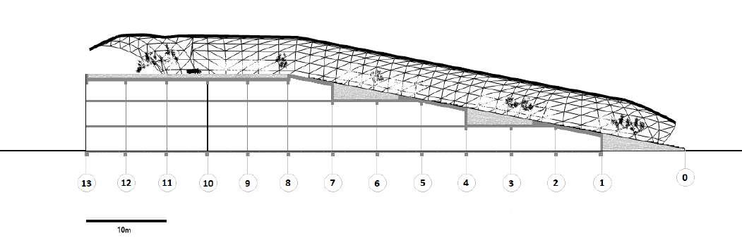
Sun path: Summer solstice peak of 87° - 89° midnoon (unfavourable) and 45°-54° midnoon Winter solstice (favourable). This affects directly solar shading and thermal control of the building.A walkable roof garden is introduced to the design to accommodate the need for green space in the city, now better at an elevated level, by making use of the large roof’s building beneath. By making use of the below-usable-heigh “pocket” (refer to Longitudinal Section Drawing), existing tree on site can be reused for planting on this roof level. The roof garden is subdivided into 2 sections: The SLOPE ROOF, and the OFFICE ROOF, named based on the underneath supporting structures. Timber gridshell roof structure is designed to provide shelter and shading experience for the roof garden’s end users, as well as a showcase of new structural technology.

Structures:
Timber gridshells with steel node connections.
Roof Garden supported by Reinforced Concrete slab.
Assembly elements:
Intensive green roof.
Sustainability Opportunities:
Daylighting
Natural Ventilation
Shading and Solar Control
THE SLOPE ROOF GARDEN: A mixture of staircase and plant areas. Staircase design is introduced to create a rest place for users, as well as serve the easy access purpose for the inclined slope. The heavily intensive plant area is achieved by the “pocket” structural design, thus this area is expected to contain a variety of vegetation, from herbaceous plants, perennials, bushes, to small trees. It offers a great potential for biodiversity.
THE OFFICE ROOF GARDEN:
Flat level roof with a continuous pathway from beginning to end, leading users towards the end point located in the East, offering an explicit picturesque view towards the Bảy Mẫu lake and the Thống Nhất Park as a whole. Smaller trees and a variety of flowers and plants are expected to be integrated into this area, mimicking the botanical garden experience at a small scale. Benches are allocated along the pathway to provide resting areas for end users.
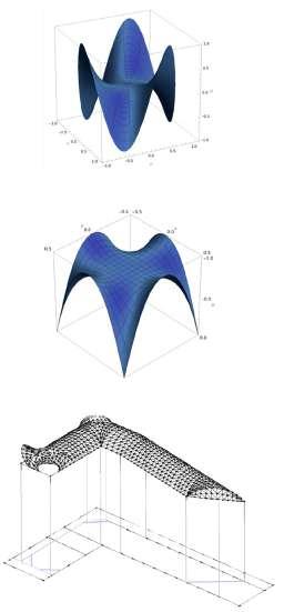
TIMBER GRIDSHELL:
Standard timber gridshell design is computed for the moderate span of 15m. Some lattice units can be opened at peak (maxima) for air flow of hot air raising effect.
Building Envelop
Energy
Materials and Carbon footprint
Others
For the garden:
Achievable using timber gridshell with transparent cladding.
Achievable using timber gridshell openings. The form-finding process is involved to generate a form for 4 openings as in the picture. At this conceptual stage the form is inspired by Laplace’s Equation topography on various domains.
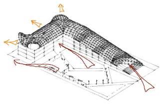
Shading is achieved through the distribution of reflective shading area accordingly. The grid will have a mixture of transparent and re-flective shading coverage, with the shading is mostly concentrated around the peak (maxima) to aid in mitigating the extreme situation of summer sun at 89 degrees, and the transparent towards the structural bearings to help scattering lower sun angle for daylighting. The detailed shading percentage and its locations will need to be computed together with the grid form. The building itself provides at least 30m shading coverage to the external Park’s space for winter sun.
Cold roof principle of wrapping everything below the green roof slab. Green roof has a good insulation performance; therefore the insulation thickness could be further reduced to minimal rigid insulation at roof level.
Minimal operation energy required.
Solar panel opportunity – can also be used as shading material. However, the maintenance as well as payback period can be less appealing.
Although standard timber beam for gridshell construction is favoura-ble, cladding material of ETFE could be less sustainable.

Rainwater & stormwater collection and reuse opportunity: With the annual precipitation of 1700mm (higher than the world average of 1000mm), there exists an opportunity for rain and storm water circulation and reuse.
A partially enclosed roof garden can be beneficial for air quality at the site by stopping direct exposure from nearby metropolitan area. Trees in the roof garden could also act like air filters for site users.
AXONOMETRIC EXPANDSION OF BUILDING
SCALE: NTS
A building block dedicated for retails and public services including shops, restaurants, restroom, and plant room. Further space subdivision depends on the type of development desired and is out of scope of this work.

Structures:
Steel frame and Reinforced Concrete slab. Steel braced bays. Retaining wall at the end of the slope.
Existing 2-storey building foundation can be reused.
Blanket raft foundation is suggested at this stage based on the geology at site of mainly fine-grained soil (clay soils) and high ground water level (near reservoir).
Assembly elements:
Double façade design is recommended if glazing envelop is desired, otherwise typical cavity wall with masonry cladding as local practice.
Open space divided further into ‘green slots’ for various uses and plans. Including an outdoor gathering stage and a café area for Office Block (See Site Plan).
For both blocks:
Sustainability Opportunities:
Daylighting
Natural Ventilation
Shading and Solar Control
Building Envelop
Operation Energy
A 3-storey building block dedicated for Start-up Incubator space’s requirement, with the precedent study of SHTP Saigon Hi-Tech Park Incubation Center (4-storey building) - heavy machinery activities for R&D testing are expected as well as office use. Standard steel frame structure is provided with braced bay to accommodate dynamic loads caused by machinery. Intensive walkable roof garden, although may increase the vibration risk on structure, can mitigate the operating noise level by offering acoustic damping. Further space’s sub-organisation depends on the type of activities desired and is out of scope of this work.
Structures:
Steel frame and Reinforced Concrete slab. Steel braced bays. Stability system may be required within the block if considerable dynamic load risk presents.
Existing 2-storey building foundation can be strengthened further. Blanket raft foundation is suggested at this stage based on the geology at site of mainly fine-grained soil (clay soils) and high ground water level (near reservoir).
Assembly elements:
Double façade design is recommended if glazing envelop is desired, otherwise typical cavity wall with masonry cladding as local practice.
Partially achievable as the 15m span - 3m ceiling height exceeds limit for daylighting control. Daylighting can be achieved around the outer perimeter – depending on how the internal space is organised and used.
Partially achievable as the 15m span - 3m ceiling height exceeds limit for natural ventilation condition. Cross ventilation design recom-mended.
Vertical louvers for East West direction, horizontals for North-South directions. Horizontal shading optimum angle of 69° is recommended, or if adjustable: 84° angle for summer to 54° angle for winter.
Double façade design is recommended if glazing envelop is desired, otherwise typical cavity wall with masonry cladding as local practice. The cavity help dissipate heat and reduces conductive heat transmis-sion to the interior surface Cold roof design with insulation wrapped below the green roof struc-ture and outside.
Out of scope of this work due to unspecified design. The operational energy can be reduced if the building fabric is well developed and monitored.
Renewables: Solar panel opportunity presents. However, the mainte-nance as well as payback period can be less appealing. The lower level of the block is shaded by existing surrounding trees, decreasing the chance for reliable solar energy opportunity.
Materials and Carbon footprint
Although Steel structure may seem unfavourable as Steel as a material is higher in Carbon footprint, the structural efficiency is much better than equivalent Reinforced concrete practice (i.e. smaller section siz-ing and less material take-off as a whole). This can be further deter-mined and justified through structure design at a later stage. Existing 2-storey foundation can be reused and strengthened further when necessary.
Jetty Garden
KTA + ARUR
External park’s space organisation study.
Silk Tree Deaf Friendly Urban Park
Ashrafi & Zad
External park’s space organisation and shading study.
SHTP Saigon Hi-Tech Park Incubation Center Incubation centre brief’s precedent study, featuring a 4-storey building. Activities inside includes machinery, R&D activities, and office use.

Green Roofs at Nanyang Technological University.

CPG Consultants
$38 million building featuring a 45 degree sloped ‘grass roofs’.
Stepped garden tops House Nha Trang Vo Trong Nghia Architects + ICADA


Intensive roof garden with trees. Concrete pocket roof top of minimum 1m depth soil bed.
AXONOMETRIC VIEW
SCALE: NTS
Crossrail Place Roof Garden - Canary Wharf, London.
Foster + Partners
Enclosed roof gardens and a leisure complex sheltered by timber gridshell structure.

NOTES:
1. ALL DIMENSIONS IN m UNLESS STATED
OTHERWISE
2. SCALE IS INDICATIVE
STRUCTURAL SYSTEM:
STAGE SLOT
STEEL PRIMARY BEAM RC FLAT SLAB
5m WIDTH BOUNDARY EXTERNAL SPACE DIVIDED INTO SLOTS FOR VARIOUS USES CAFÉ AREA FOR OFFICE BLOCK
ROOF GARDEN LEVEL:
• TIMBER GRIDSHELL WITH STEEL NODE CONNECTION
• 250mm MINIMUM DEPTH ONE-WAY SPANNING REINFORCED CONCRETE SLAB
BUILDING BLOCK:
• STEEL FRAME: COLUMN AND BEAM WITH BRACING
• 200mm MINIMUM DEPTH ONE-WAY SPANNING REINFORCED CONCRETE SLAB*
FOUNDATION SYSTEM:
CONCRETE BLANKET RAFT FOUNDATION** STRIP FOUNDATION AT RETAINING WALL
* GROUND AND FIRST LEVELS FOR SLOPE BLOCK CAN BE REDUCED TO RC FLAT SLAB DUE TO SMALL SPAN OF 7.5m x 5m
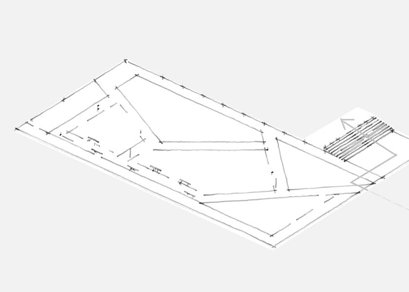
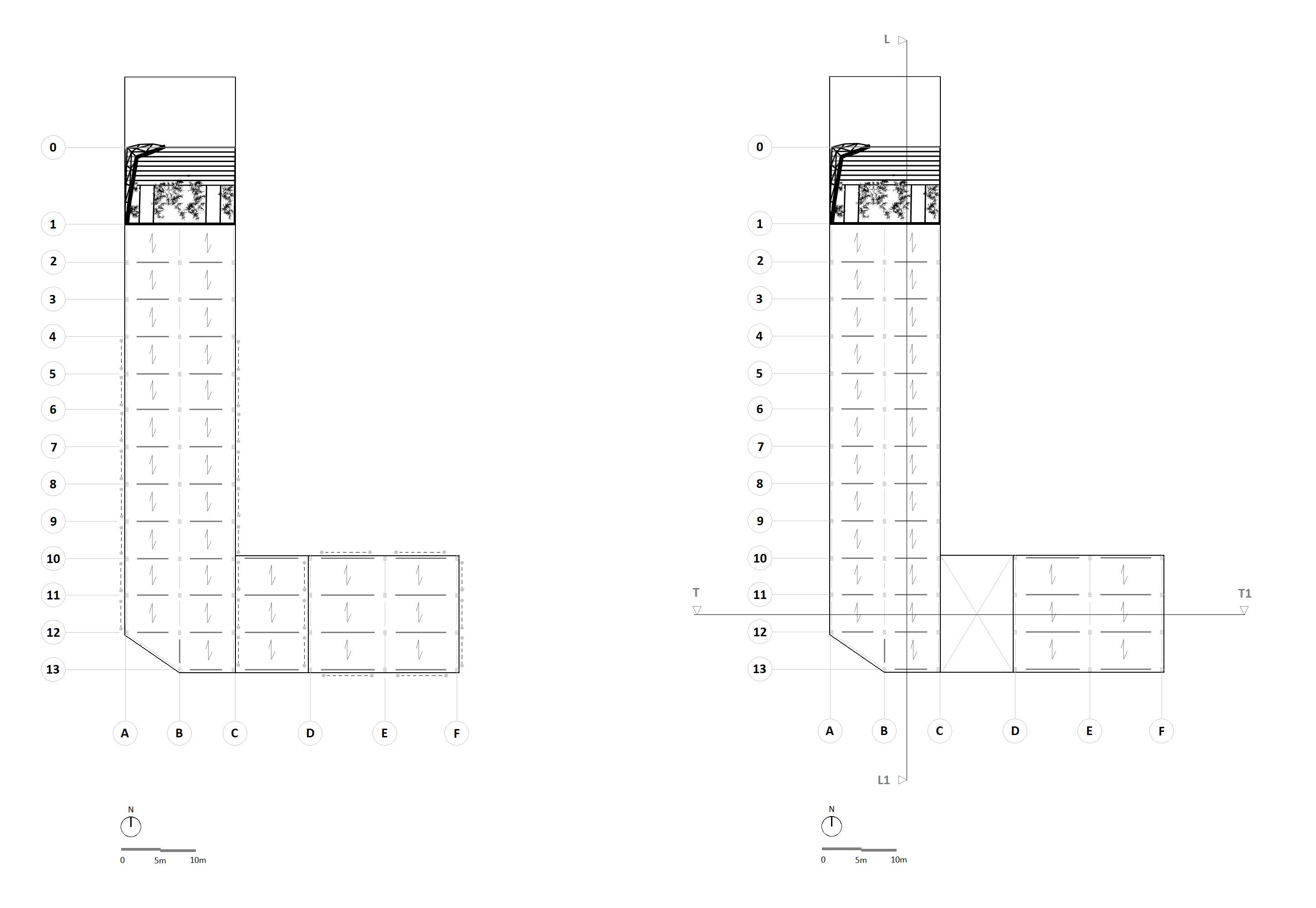
PLAN ON SITE SCALE: NTS
END OF SLOPE RETAINING WALL 200mm ONE-WAY SPANNING RC SLAB SPANNING DIRECTION STEEL PRIMARY BEAM STEEL COLUMNS STEEL BRACED BAYS WALK-THROUGH GATE WALK-THROUGH GATE
FLOOR PLAN AT +7m FLOOR PLAN AT +3m TRANSVERSE SECTION T - T1 LONGITUDINAL SECTION L - L1
TIMBER GRIDSHELL WITH METAL CONNECTION STEEL PRIMARY BEAM
200mm ONE-WAY SPANNING RC SLAB
STEEL COLUMNS
250mm ONE-WAY SPANNING RC SLAB INDICATIVE BLANKET RAFT FOUNDATION INDICATIVE BLANKET RAFT FOUNDATION RETAINING WALL @ STRIP FOUNDATION
USABLE HEIGHT @2m MINIMUM
ENTRANCE WALK-THROUGH GATE INDICATIVE BUILDING ENVELOP SCALE: NTS
SAND BASE
SOIL AND GRAVEL BASE GRANITE PAVEMENT BRICK CLADDING CAVITY MIN 50mm RIGID INSULATION OSB SHEATHING STEEL PLATE @BEAM STEEL ANGLE
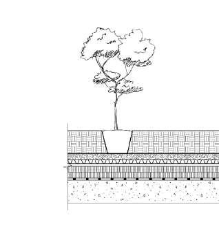
GROWING MATERIAL SOIL AND GRAVEL BASE FILTER AND DRAINAGE LAYER ROOT BARRIER EXTRA DRAINAGE LAYER WATERPROOFING MEMBRANE STRUCTURAL RC SLAB
WALL-TIE EDGE COLUMN RC SLAB PRIMARY BEAM SUSPENDED CEILING
INNOPARK
INNOPARK DESIGN PROJECT: INNOPARK
© My K V. Software licences belong to Imperial College London. 14
BUILDING PLANS AND SECTIONS BUILDING ENVELOP SYSTEM DATE: 11/09/2021 DRAWN BY: MKV
July- December 2021
Simpson Strong-Tie Vietnam
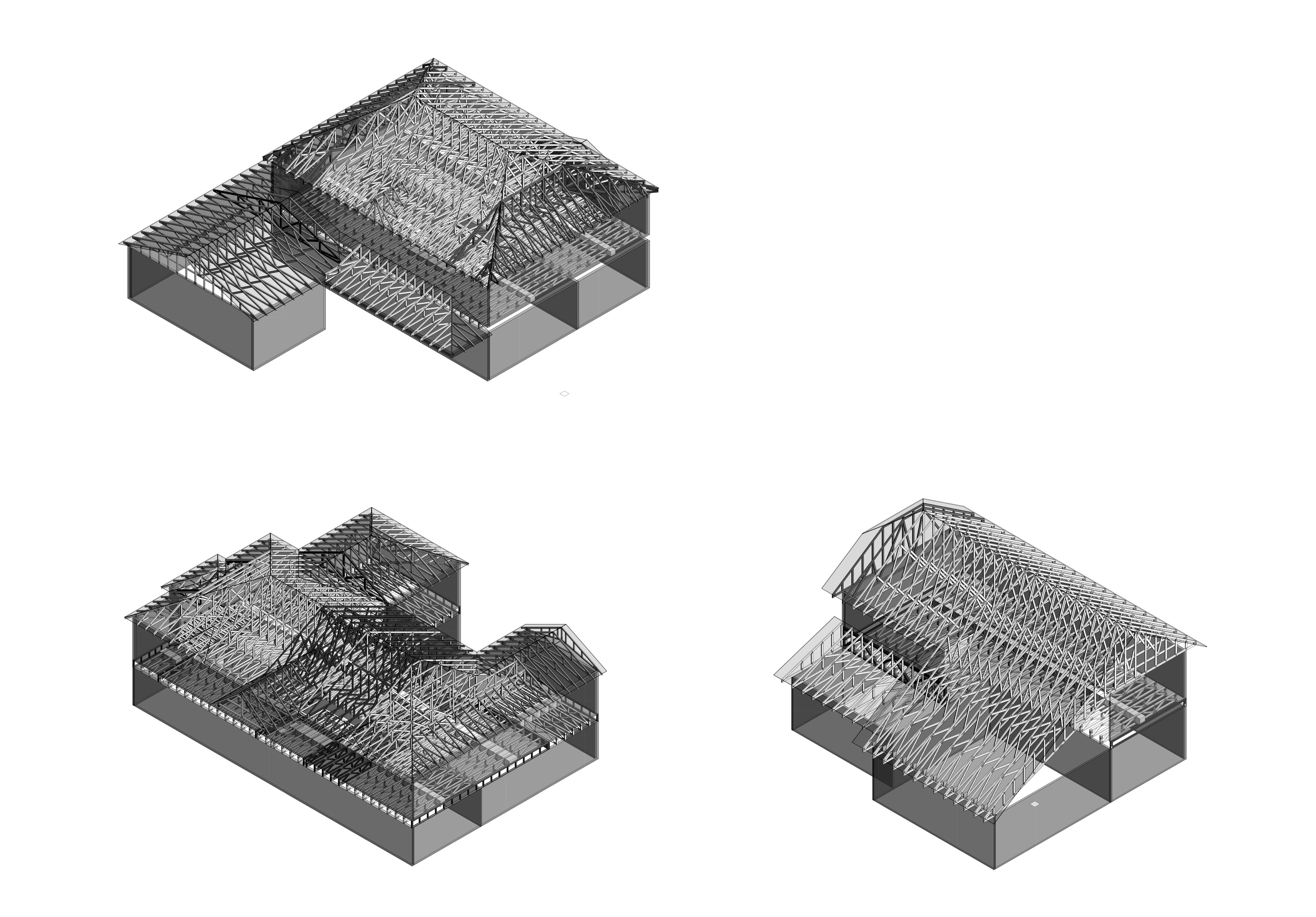
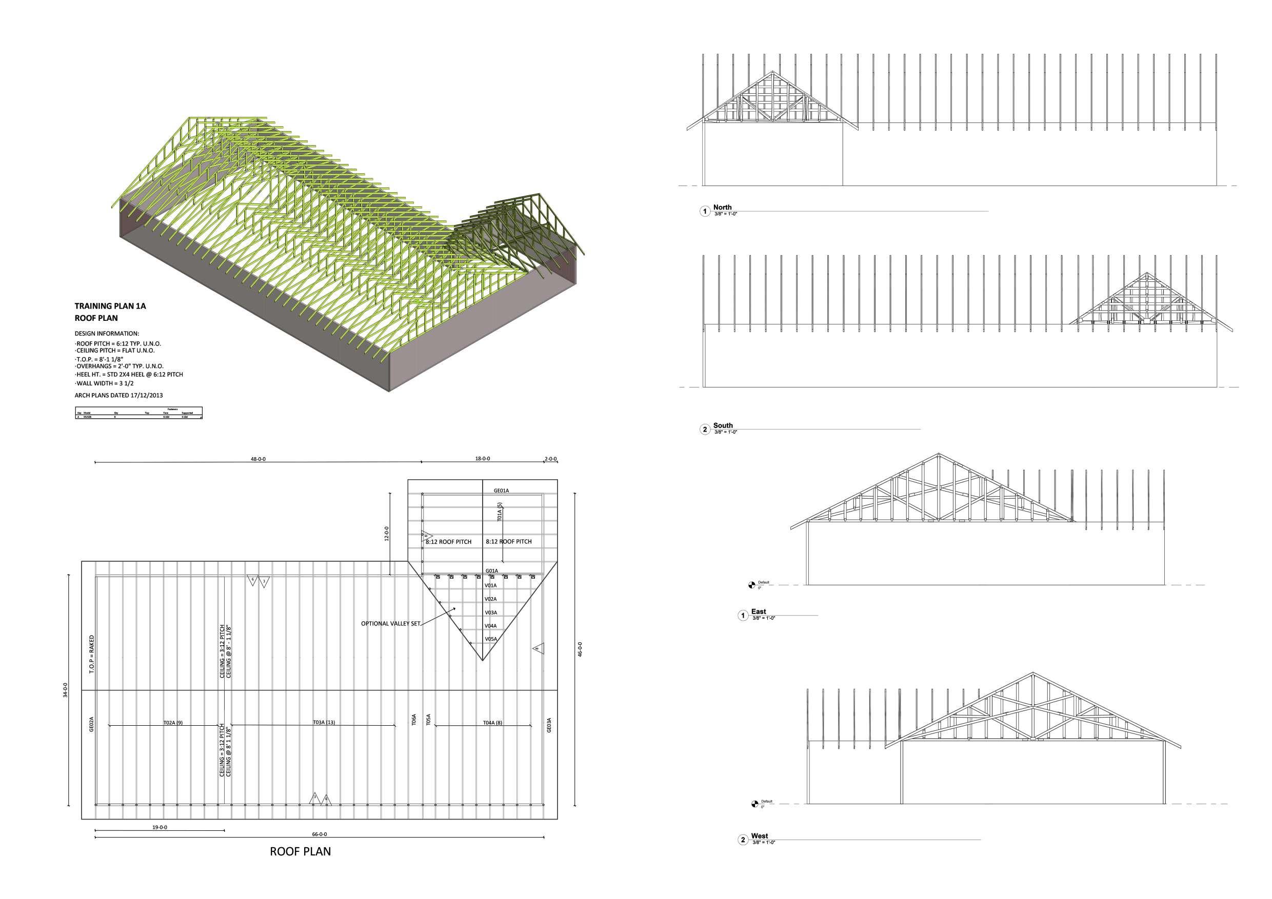
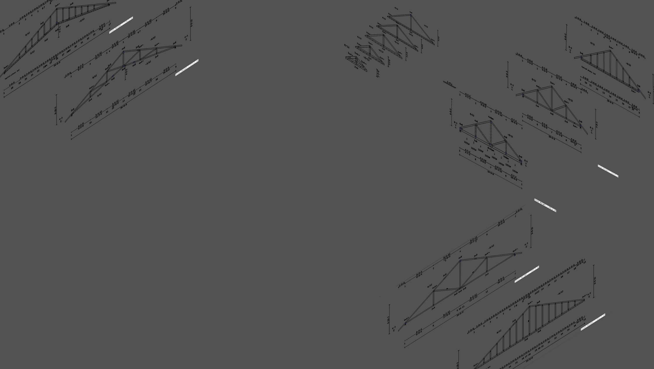
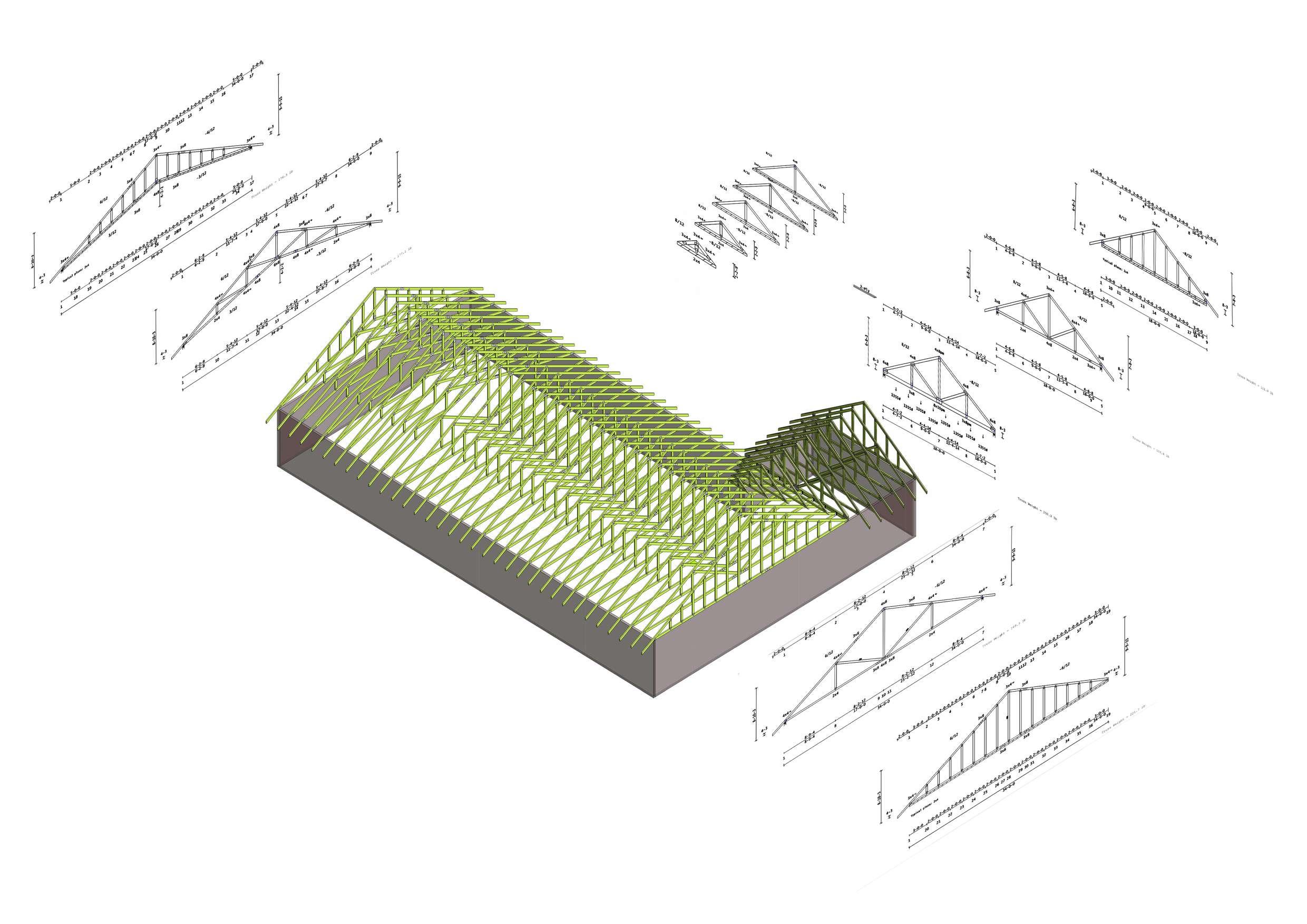
The daily work, from a full-time job, is to design timber trusses for North American client for a range of domains including residential (mainly), commercial, and agricultural. Display permission is granted by employer for training work pieces only.
Simpson Strong Tie Vietnam Company Limited
A series of training projects consisting of modelling and designing every single structural truss element to produce technical drawings, models, and quantity outputs ready for QA and manufacturing. The design duties include truss subelements of top and bottom chords, webs, and connections of plates, hanger, and bearing.
Simpson Strong Tie Vietnam Company Limited
Basic residential plan with a ceiling and a valley set. Each piece of truss has its own technical drawing illustrated briefly as in the photo, designed using building code IBC2018, truss code TPI-2014 and loading standards from ASCE7-16 code of practice for United States market.
Group Project
March - April 2019
The University of Sheffield
This is the first project belongs to a series named Integrated Design Project Series consists of 3 project phases numbered accordingly. Provided public consultation graphic design, geotechnical data analysis, conceptual architectural and structural design solutions.
NEEPSEND
Sheffield City Council (SCC) have reviewed the masterplan proposals and have decided to proceed with the redevelopment of the site of the former Neepsend Gas Works as an outdoor recreation centre with a community focus, which will be linked to The Outdoor City @ Parkwood Springs, and act as a catalyst for the redevelopment of the Neepsend area in the longer term. Parkwood Sprind’s site redevelopment includes 3 projects:
THE
The project includes an indoor ski slope in Yorkshire to compete with the similar precedent studies of The Chill Factore in Manchester and Snozone Yorkshire in Pontefract, UK. They want this site to seamlessly integrate with the indoor ski slope’s end being constructed separately in Neepsend Project.
Follows THE OUTDOOR CITY project which acts as a catalyst for the redevelopment of the Neepsend area in the longer term, this project requires further brief and Masterplan from the SCC. This project is not a part of the IDP series but included for the purpose of completeness.
NEEPSEND
Main project site of the IDP series. The team is appointed by SCC to examine the feasibility of the proposed development and undertake the scheme design. Tasks include devise and evaluate alternative site layouts for the redevelopment, alternative structural arrangement options for the large indoor ski slope hall, tram routes, structures, and options for addressing the associated civil engineering issues.
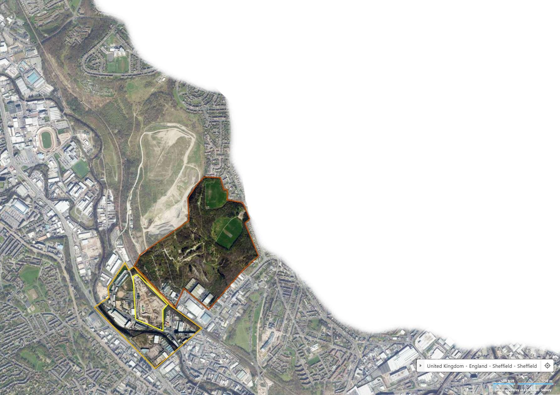
Neepsend, Sheffield, Uk
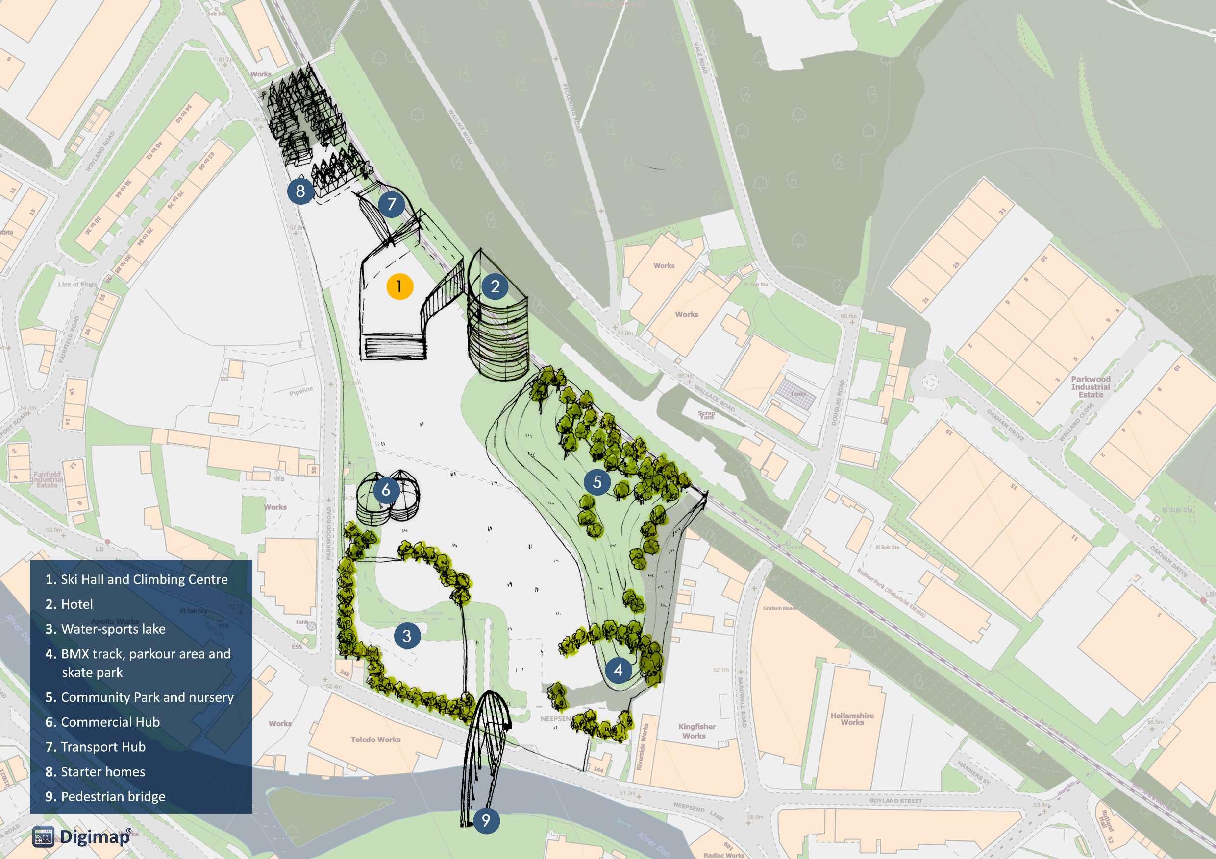
As a full site development, the client wants to add the following features and structures within the Neepsend site boundary:
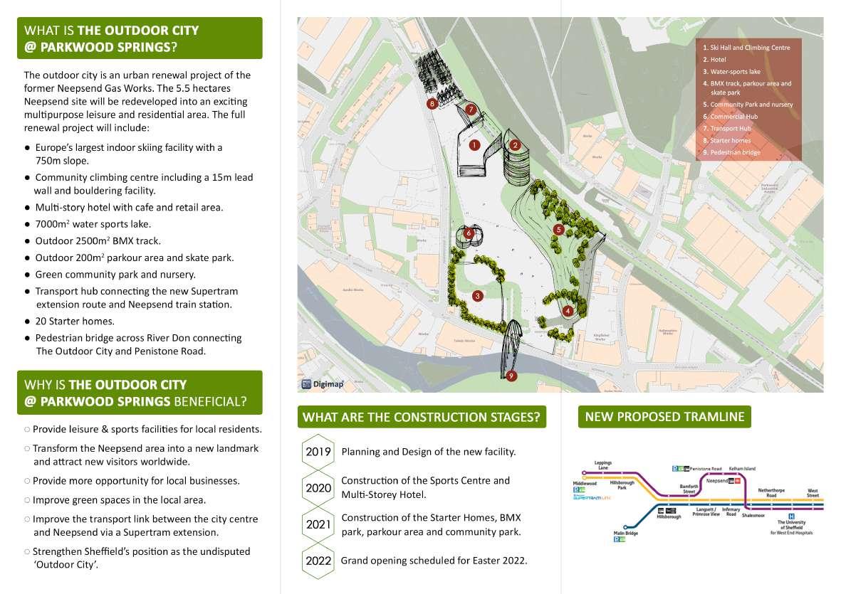
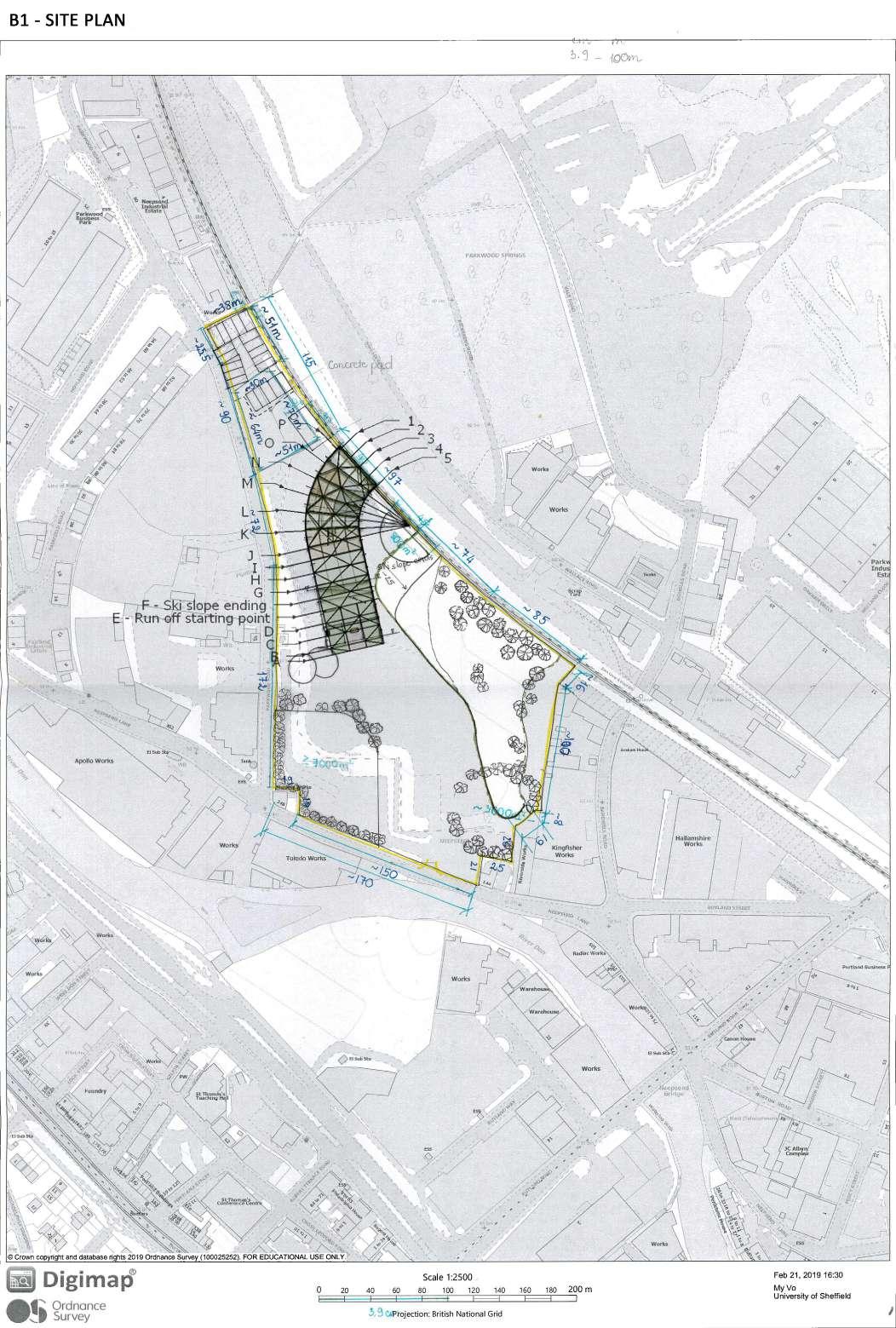
Ê A 70m long by 40m wide indoor ski slope. The top of the slope will be at the same level as the bridging structure, allowing skiers to descend uninterrupted over part of the slope from the top of Parkwood Springs to river level. The remainder of the slope will be dedicated to beginners. This structure is to include a nursery and a cafe.
Ê A community climbing centre with a 400m2 (on elevation) lead climbing area, featuring walls up to 15m high and a 800m2 bouldering area (on elevation.)
Ê An outdoor 2,500m2 BMX track.
Ê A 200m2 parkour area and skate park.
Ê A 7,000m2 lake, suitable for teaching water sports (e.g. kayaking, paddle-boarding). Proposals for linking the lake directly to the River Don would be welcomed.
Ê Community Park and nursery
Ê 150 bed hotel with retail and dining at ground floor
Ê Retail and dining
Ê 20 starter homes
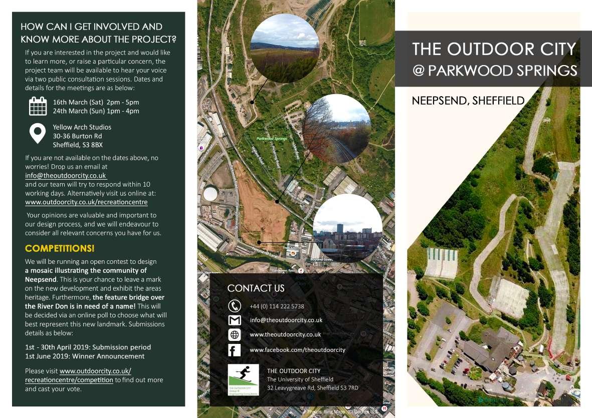
Contain introduction information of the site project. Used for public consultation purposes.
Text: Jeff Tsun.
Photos: ©George Sheppard
Tramline design: James Thompson
Map base: Digimap and Bing Map.
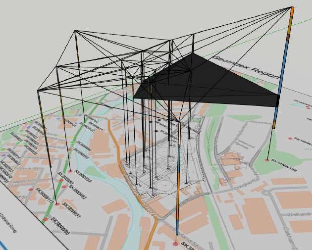
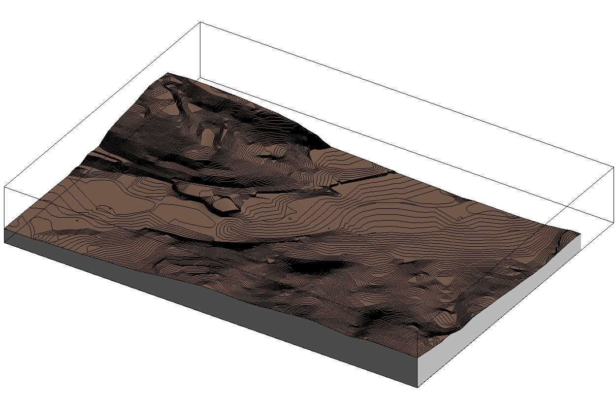
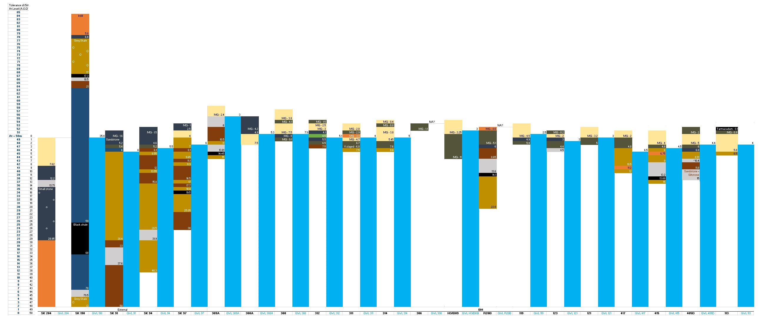
A site investigation pack has been provided, giving some historical, geotechnical and geo-environmental information about the site and the surrounding area. Boreholes visualization using Excel for constructing 3D interactive map and Boreholes 3D interactive map using Sketchup for the analysis of ground conditions are designed to help the team with:

Ê A description of the site geology and the ground conditions assessment.
Ê A geotechnical ground model for the site.
Ê Preliminary foundation strategy (including characteristic soil properties) for the buildings, pedestrian bridge, and the legacy development.
Ê An assessment of the design and construction risks.
 GROUND SURFACE GENERATED BY REVIT USING DIGIMAP DATA
Boreholes visualization
BOREHOLE CONNECTIONS FOR INDICATIVE GROUND SECTION
COAL LAYER PREDICTION FROM BOREHOLES INFORMATION
GROUND SURFACE GENERATED BY REVIT USING DIGIMAP DATA
Boreholes visualization
BOREHOLE CONNECTIONS FOR INDICATIVE GROUND SECTION
COAL LAYER PREDICTION FROM BOREHOLES INFORMATION
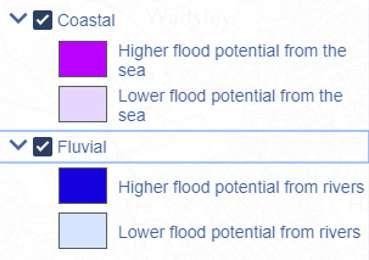
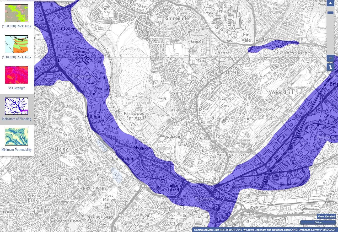
The flood resilience measures are conducted. Data obtained from Digimap indicates that the lower part of the site is ‘Flood Zone 2’- high risk of flooding from the nearby river. This has a big impact on the design of Foundations of the site’s structures, Drainage system, and Sustainability design of Water management.
Mitigation:
• All buildings are constructed on the upper slopes of the site, mitigating risks caused by flooding. The lower part of the site is reserved for ‘low value’ application such as the Water Sports Lake and general landscaping.
• Storm sewers have been designed to withstand a 5-year design storm, consistent with UK practice for vulnerable land subject to significant flooding. This approximately equates to a 1 in 30-year flooding event.
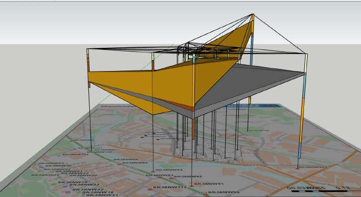
BRIDGE AND SKI COMPLEX.
My conceptual design proposals for 2 main structures in Neepsend Project: The Ski Slope and The Pedestrian Bridge will be presented next.
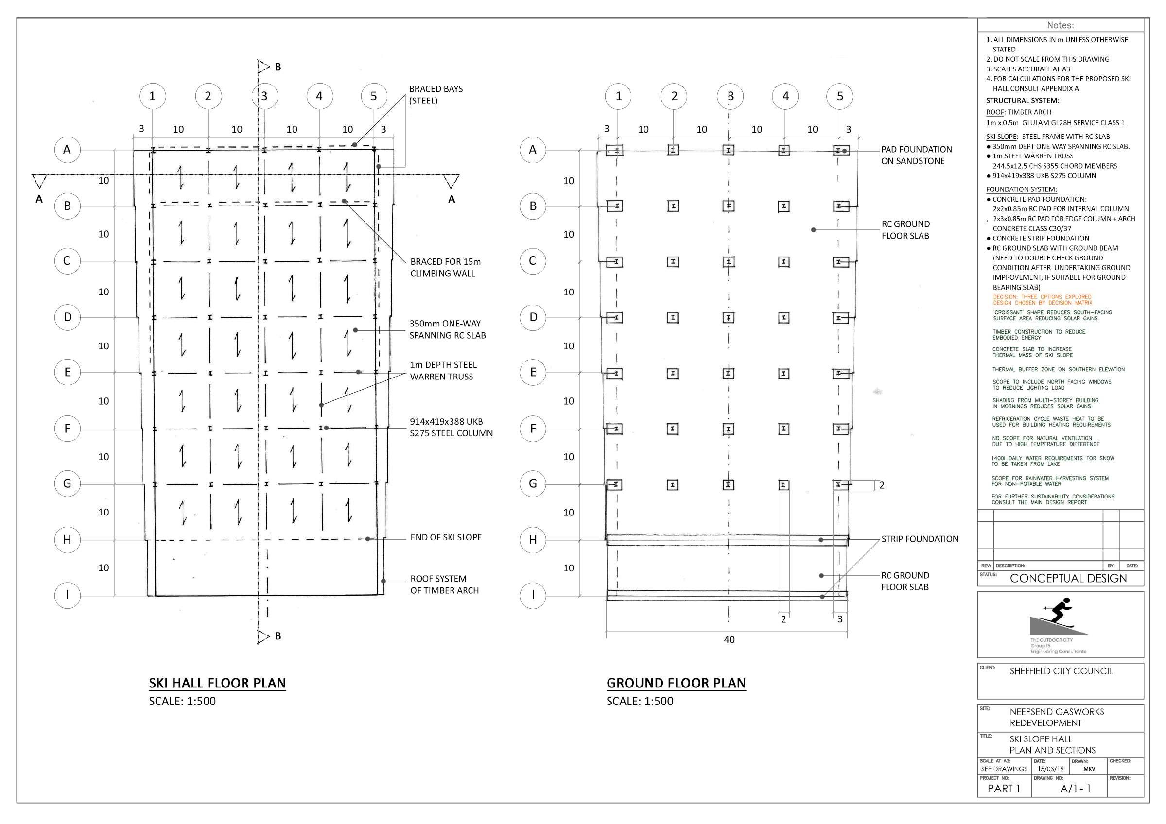
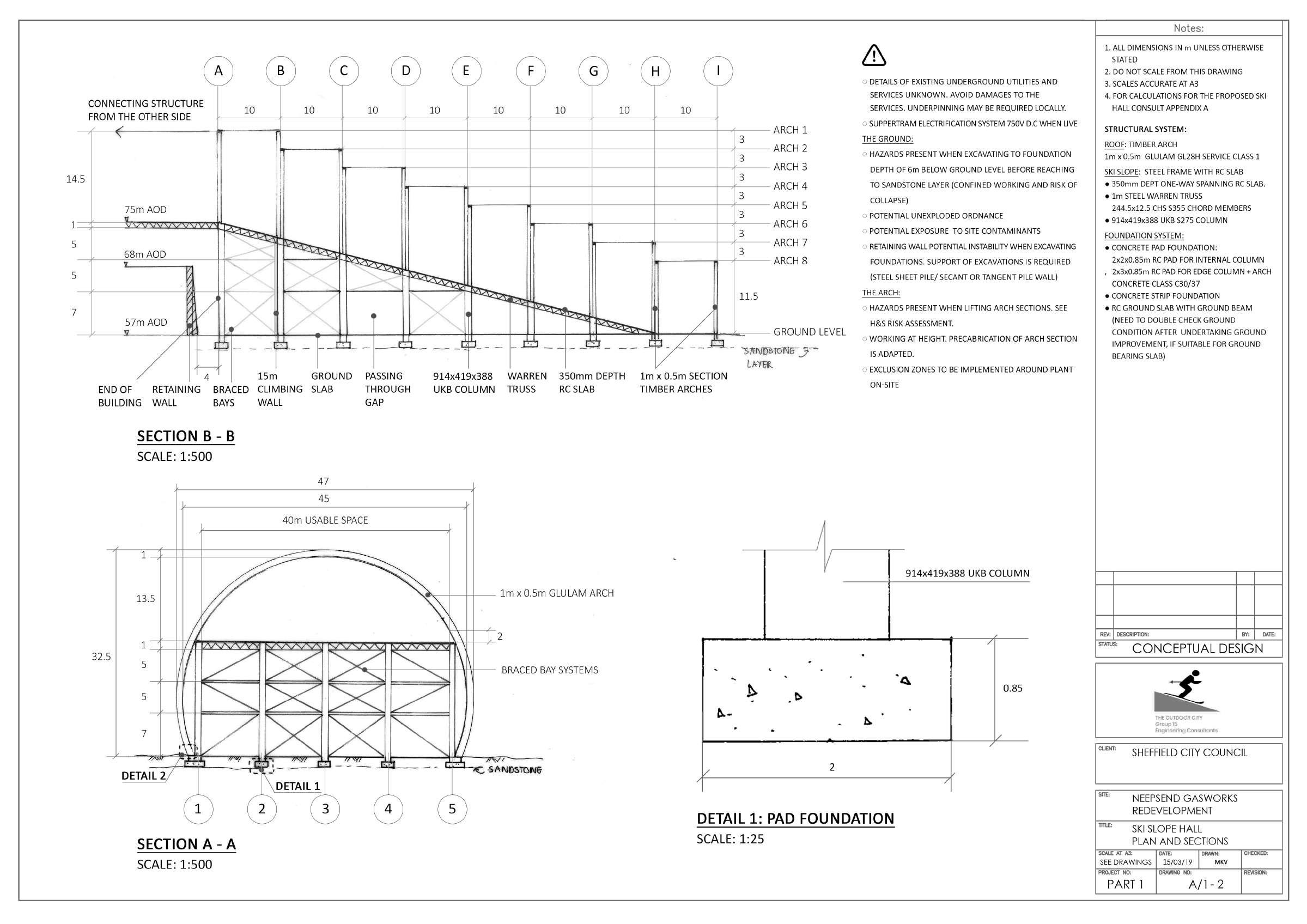
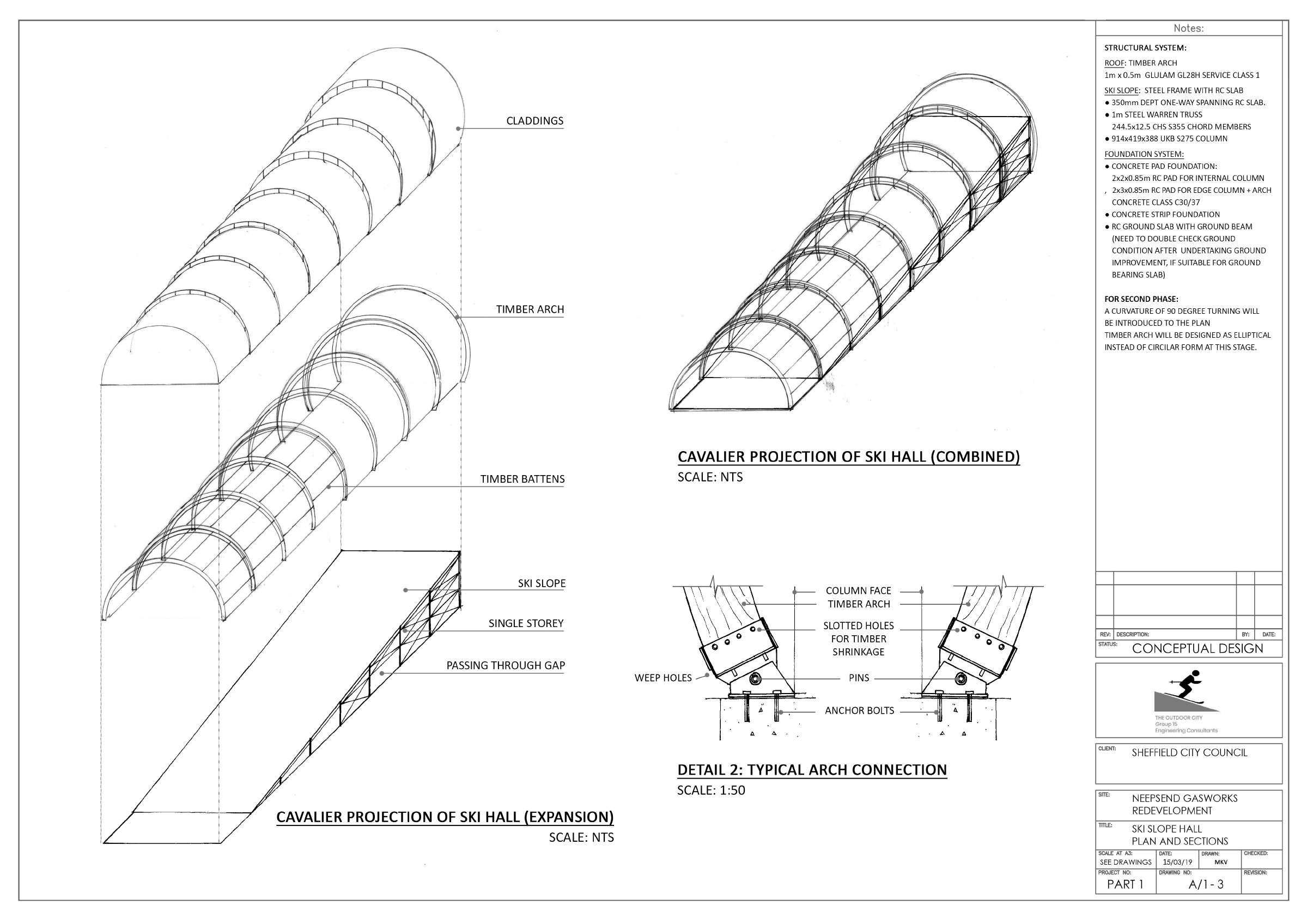
My conceptual design, preliminary structural sizing, and drawings for the complex building consists of a Ski Slope Hall and a Climbing Centre- featuring a 15m height climbing wall and a bouldering area.
Materials: Timber, Reinforced Concrete, Steel.
Structure:
Ê Timber arches roof structure and bracing.
Ê RC concrete slabs.
Ê Steel frame structure below the Ski Slope.
Ê Pad foundation.
Drawings:
Ê Plan.
Ê Section and foundation.
Ê Projection and connections.
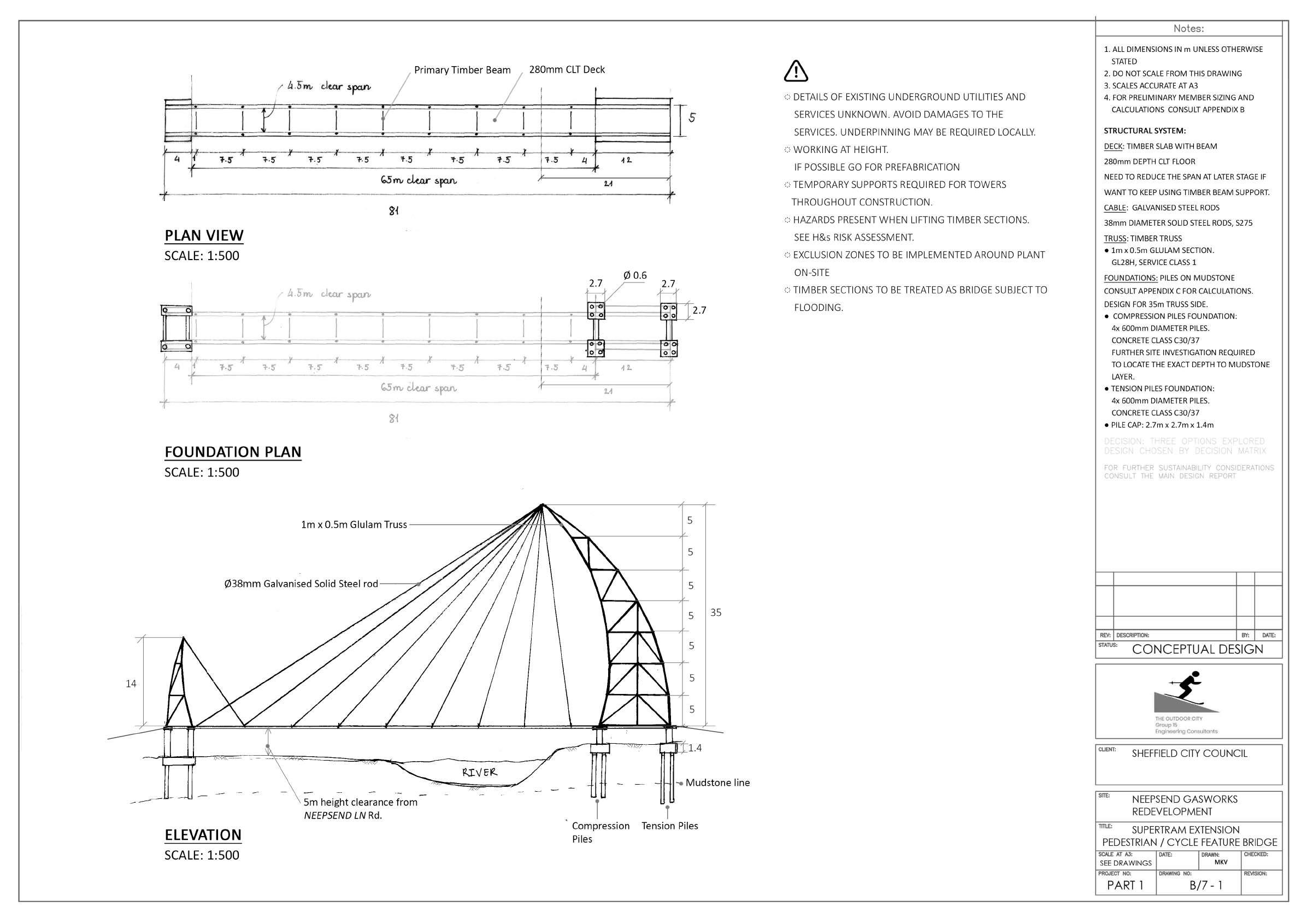
My conceptual design, preliminary structural sizing, and drawings for the client’s requirement of a pedestrian bridge over the river and the adjacent road to site. Detailed design suggested that the structure might fail in connections between Timber truss and foundation, hence the Crescent truss might need to be changed to metal grid.
Materials: Timber and steel.
Structure: Crescent-shaped cantilever with steel cable.
Drawings:
Ê Plan and section.
Ê Cavalier projection.

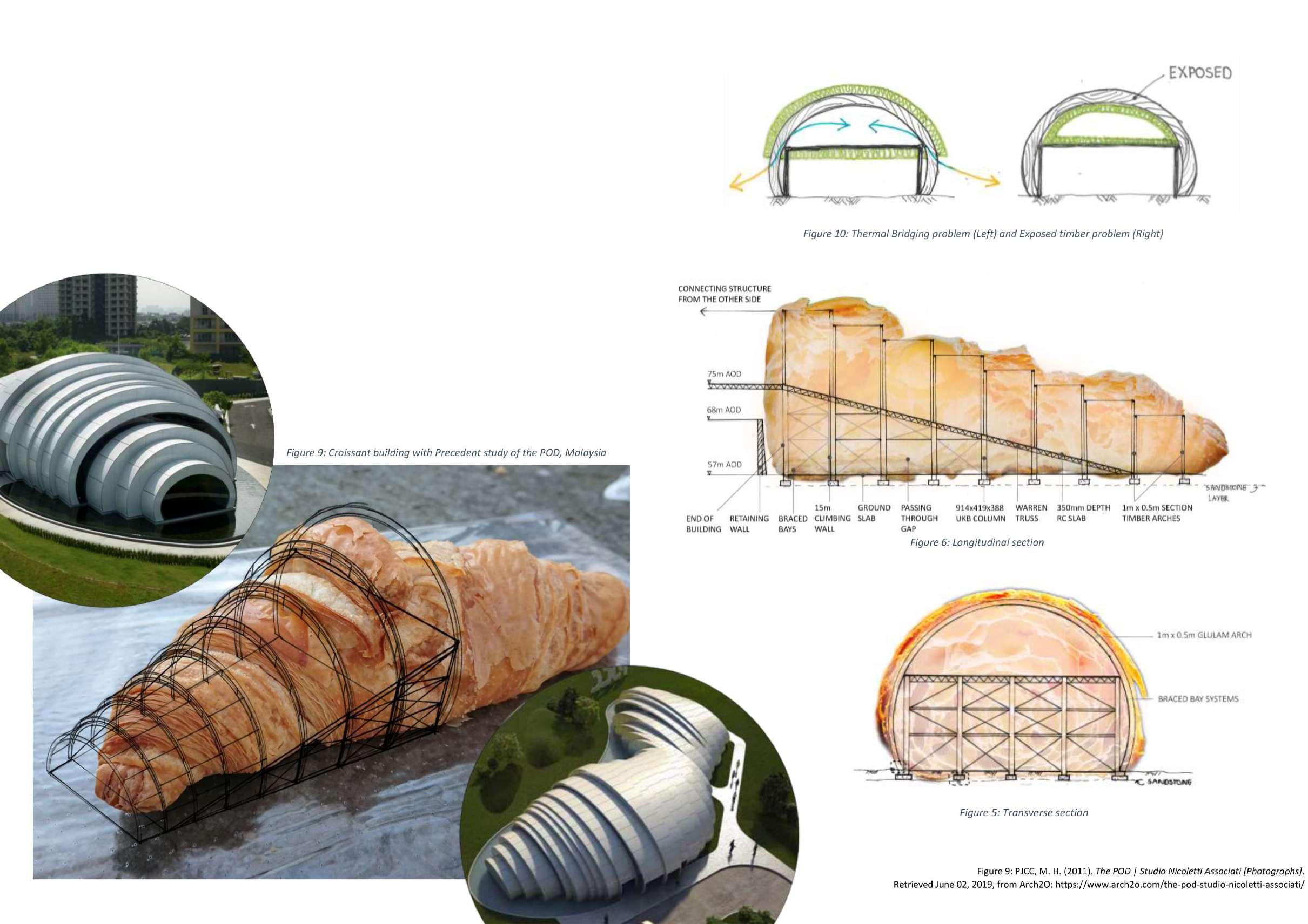
My conceptual design for the Ski Complex consists of a Ski Slope Hall and a Climbing centrefeaturing a 15m height climbing wall and a bouldering area. Inspired by the croissant shape with a precedent study of The POD Pavilion by Hijjas Kasturi Associates Sdn with Studio Nicoletti Associati in Kuala Lumpur, Malaysia, although the water droplets were the inspiration for The POD’s structure. Elliptical rings, despite structurally challenging, are chosen to accommodate and embrace the changing in slope direction - introduced at later detail stage, while also optimise the internal space occupied compared to typical parabolic arch – enough to enhance user experience but not too large to affect the cooling and maintaining the strictly controlled internal temperature. Thermal bridging was identified to be a problem for later environmental design evaluation.
Individual Project
April - June 2019
The University of Sheffield
This is the second project belongs to a series named Integrated Design Project Series consists of 3 project phases numbered accordingly. A detailed design focused on sustainability and low -carbon building criteria.
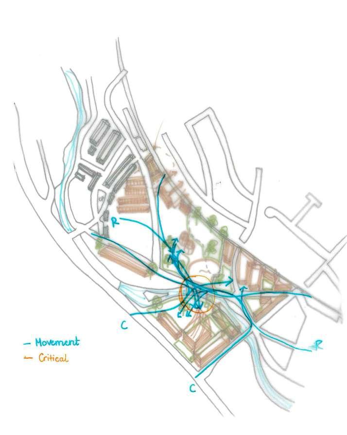
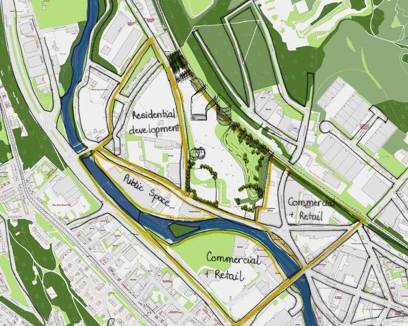
An overall review is performed to ensure the connection between 3 projects of SCC, including the Local Redevelopment Project where new housing areas are planned to be developed around Neepsend site. It is predicted that a large proportion of the Local Redevelopment Project will be for residential purpose, follows by commercial uses and public space. Target audience of residential development is students from the nearby university and local young people who will have the need for socialise public space, which is beneficial to the development of Neepsend Project. Movement study is briefly conducted to assess the transition between spaces and the accessibility of Neepsend site.
This second project is aiming at the design of the complex building, consists of an Indoor Ski Slope and a Climbing centre featuring 15m height climbing wall, within the Neepsend’s redevelopment plan (Neepsend site project). As outlined in the first project’s brief, the Ski Slope in Sheffield, within this plan, is to be competed with Chill Factore Ski Slope building in Manchester, now rebranded as BEYOND retail-mix complex building, for the size record not only within the UK but also to be “the no.1 EU Ski Slope”.
The Ski complex also needed to be designed sustainably with the 2 clear requirements from the clients and the SCC:
• Energy: Reduce energy consumption within construction and operation, increasing energy efficient performance. 10% onsite renewable energy.
• Materials: Reduce initial embodied carbon footprint of the construction and in operation.
An overall design solution for the building, which was developed during Project 1 (IDP 1), is reviewed. The calculated fund for the project is £20 million, £11.2 million less than the cost of the Chill Factore. In developing the strategies, it is required to consider: the architectural design process, structural design solutions, thermal comfort, lighting, ventilation and acoustics.
• 70m long by 40m wide indoor ski slope. The top of the slope will be at the same level as the bridging structure (see below), allowing skiers to descend uninterrupted over part of the slope from the top of Parkwood Springs to ground river level. The remainder of the slope will be dedicated to beginners. This structure is to include a nursery and a cafe.
• A community climbing centre with with a 400m2 (on elevation) lead climbing area, featuring walls up to 15m high and a 800m2 bouldering area (on elevation.)
• It is required to have a connection to the end of a ski slope coming from the Parkwood Springs slope. This is where is crosses over the railway at a slope level of 75m AOD with a 2m deep structural depth below this. This is the start of the 70m long slope.
Guidances used in this project for environmental design:
• Daylighting – CIBSE LG10 (2014)
• Natural Ventilation – CIBSE AM10 (2005)
• Solar Control – CIBSE TM37
• Thermal Design – CIBSE Guide A (2015)
• Renewables – CIBSE TM38 (2006)
• Energy Strategy – CIBSE Guide F (2012)
A detailed design solution for the following is required:
Superstructure solutions:
• Structural design solution for the building (or different elements of the building) and its justification
• Element sizing – with supporting calculations to demonstrate the feasibility of the proposed solution.
• Materials Strategy including choice of materials.
Environmental Design solutions:
• Ventilation Strategy.
• Heating & Cooling Strategies.
• Lighting Strategy.
• Acoustics Strategy – areas for concern level and mitigation strategies only.
• Energy Strategy
THE QUESTION:
Given the project vision of being “a leading sustainable, low carbon, iconic building that is a showcase for innovation in Sheffield” – as mentioned within the brief, as one of the environmental consulting engineers for the project, I am not fully convinced that this project could really be regarded as “sustainable” in terms of its environmental impact. The project is a massive HVAC block being put in a never failing below 0°C environment. “Environmental sustainability” in building practice normally requires a high level of occupant’s adaptability to the surrounding environment (adaptive environment) while the nature of the Indoor skiing is climate-controlled environment. The requirement of “leading sustainable” sounds confusing enough, and being an “iconic building for Innovation showcase” is another story. Without being given much sociocultural context and demand survey level within local and regional context, it remains questionable whether already a demand for having a complex multi-sport site has been investigated at the location to begin with, given that there now exists the Chill Factore Ski Slope 45 minutes away by train in Manchester, and the past success of Ski Village is unlikely to guarantee that the demand will remain the same within the region. Thus, it could eventually lead to a lower demandoversupplied market.
Giving that the nature of the project has been already against the natural environment, and its geometry of an inclined slope with minimum width of 40m, I have little doubt that the adaptive sustainability principle will unlikely to be achieved for the Ski Slope’s main building, depending on how “Sustainability“ is defined.
The direction of this project aimed for demonstrating that Environmental Sustainability is unlikely to be achieved, delivering a more sustainable solution considering both Environmental (Environmental sustainability), within limits, and Socio-economic factors (Socio-economic sustainability). In the project solution proposal, the evidence for achieving “environmentally sustainable” practice’s standard possibility was illustrated, and how the incorporation of Socio-cultural-economic might save/boost the building sustainability practice’s status. However, it was unable to tell an exact figure of how “sustainable” the building is compared to normal practice, as there exists multiple outputs that are heavily dependent on the client’s decisions, especially in terms of stakeholders, cost, and funding. Nonetheless, the project gave me an enormous opportunity to study environmental design practices.
Local climate information is obtained for site analysis purpose, particularly to outline conceptual passive design strategies
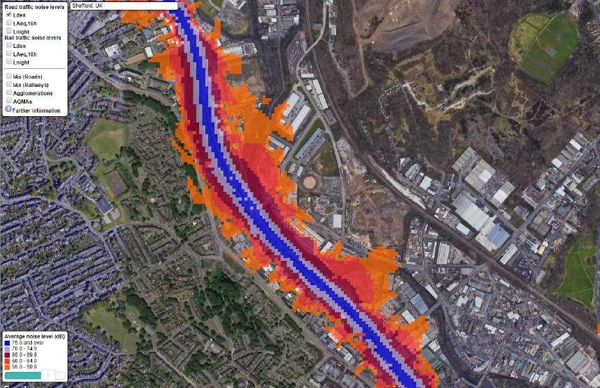
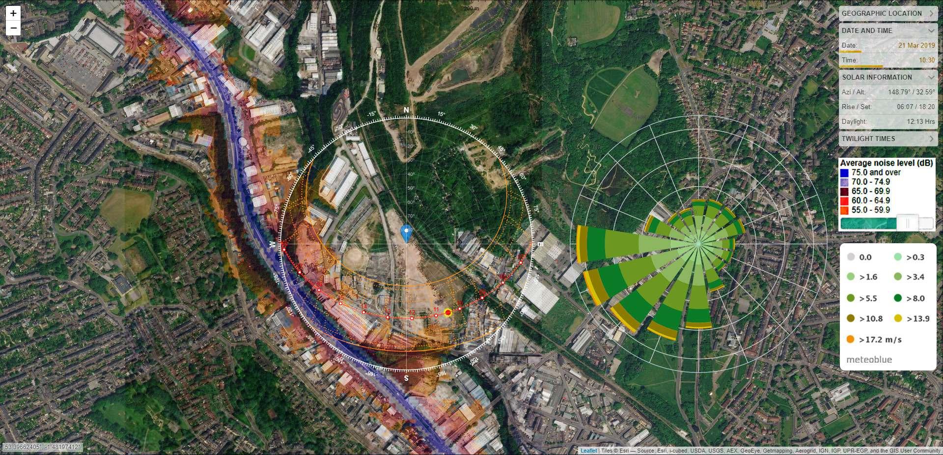
Climate information on photo:
● Sun path
● Wind rose
● Noise map
Others site information included in the submitted proposal:
Weather and microclimate:
● Seasons and temperature
● Precipitation
● Average sunshine hour
● Shadowing
● Snow
Air quality
Historical use of site
Transportation and circulation
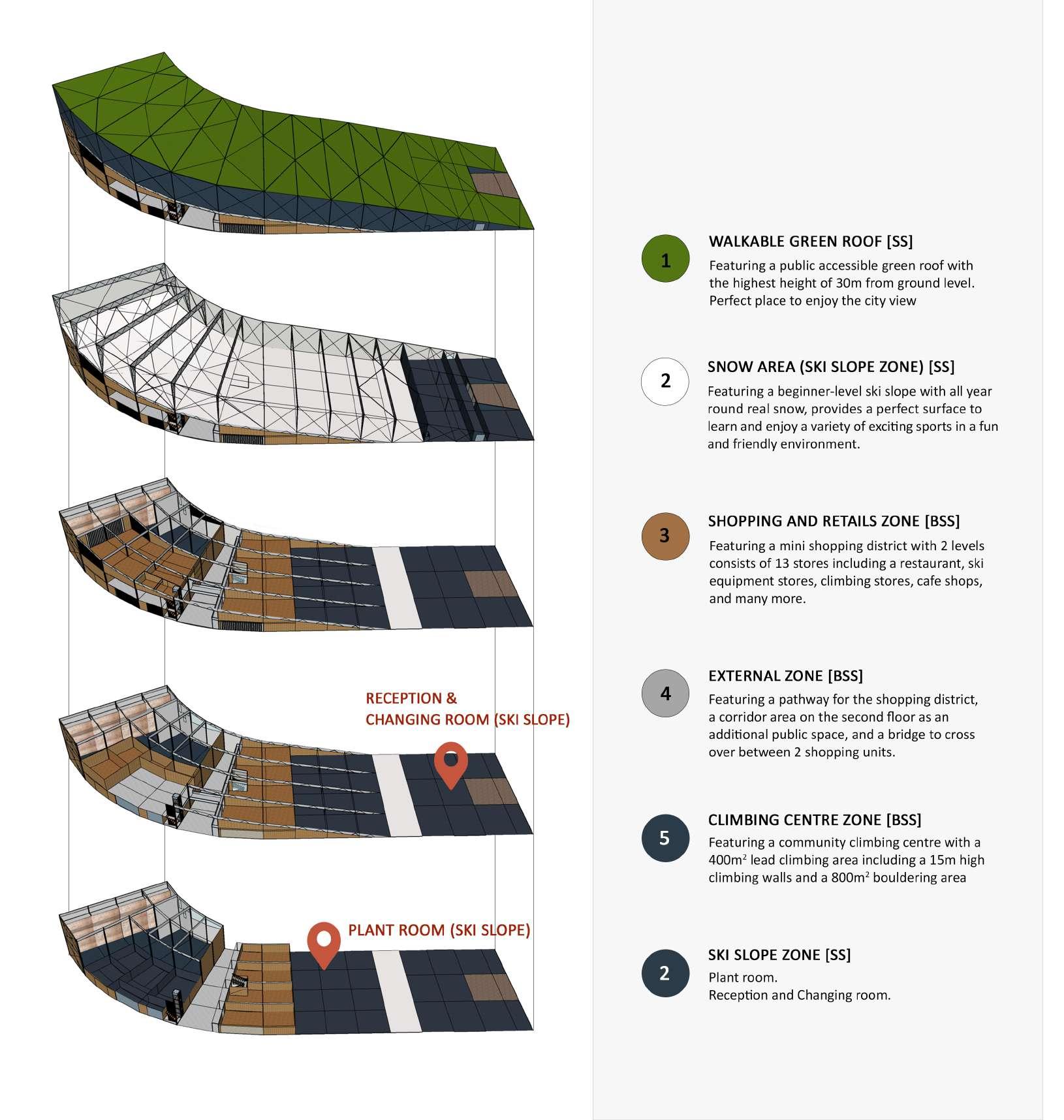
The complex building has 2 separate components:
• Ski Slope [SS]
• Below the Ski Slope [BSS]
And 5 zones as indicated within the circle below including:
Featuring 5 zones as shown. The structure below the Ski Slope stayed the same, while the timber arc was changed to steel moment truss to accompany the heavy public-accessible green roof. The green roof: It’s predicted that the zone below the Ski Slope was unlikely to work out for passive design due to unfavourable geometrical conditions, while the Ski Slope Hall was also not in the same need due to its stringent restriction in temperature control of ±1°C. Thus, to enhance the sustainability credit, a walkable green roof was introduced to enhance the social sustainability credit for the whole complex.
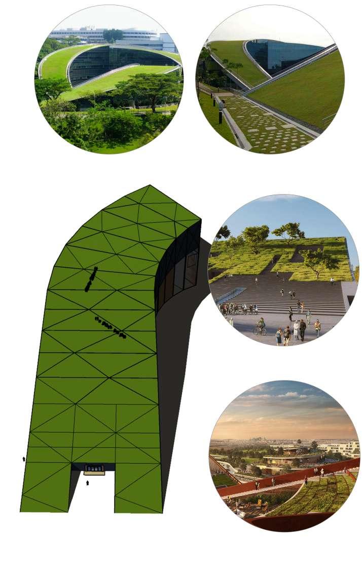
 Precedent study: Nanyang University’s green roof
Budapest museum design proposal by Napur Architect
Precedent study: Nanyang University’s green roof
Budapest museum design proposal by Napur Architect
ROOF:
Structure: Green roof supported by concrete slab. Wall components: Warm roof principle of wrapping everything around the structure. Green roof has been discussed to have a good performance on insulation, therefore insulation thickness reduces to 200mm rigid insulation at roof level.
Structure: With the span of 40m minimum and a heavy load of dead load from the sedum and dynamic load from people movement at roof level, Steel structure will be chosen to guarantee the required stiffness and stability of the structure.
Wall components: Wall: “Burrito wrap” of 500mm thick blown mineral fibre insulation and reduces to 300mm at roof level, covering the whole snow area. 300mm thick insulation standard for the transition between the snow zone and the Changing room.
Structure: The proposed structure of Steel frame for BSS zone from Project 1 will be kept the same - due to its complication in zone divisions and interactions below the Ski Slope, as well as heavy load of ski activity and extreme height difference from ground level, at the highest of 18m.
Wall components: Unable to have a defined strategy as greatly depended on zone divisions and type of activities presented. As the structure is Steel frame, a standard wall component is recommended.
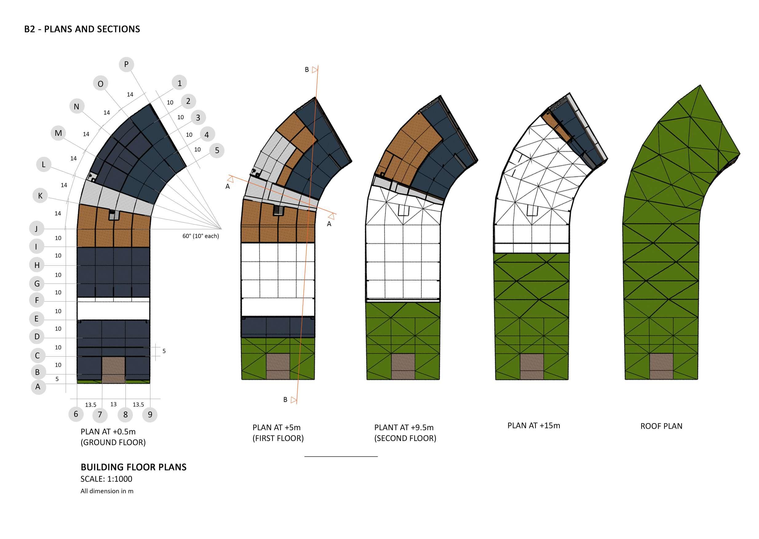
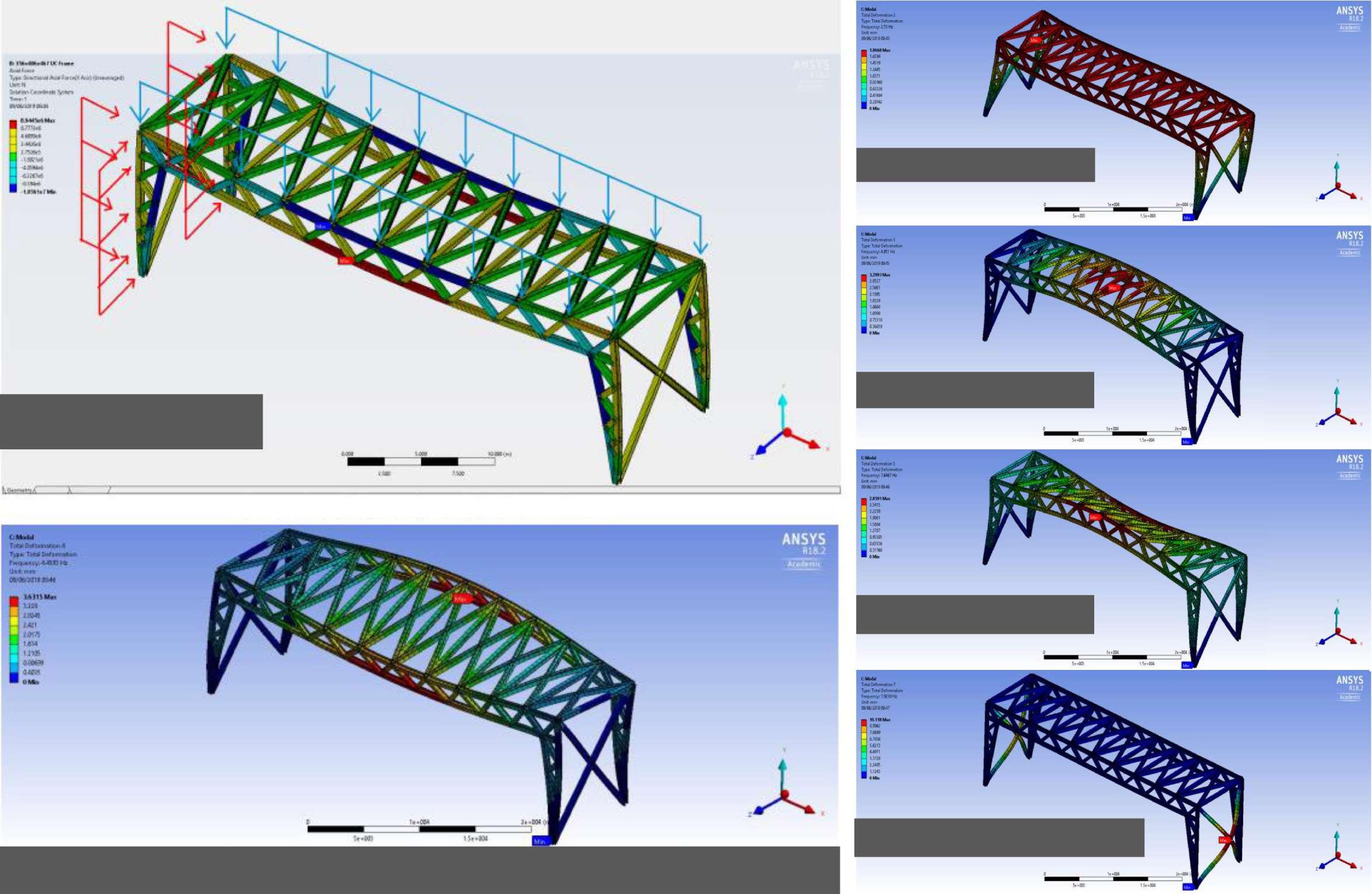
An overview of the structure system planned for the whole complex.
In plane bracing is partially displayed
Transfer structure system analysed using ANSYS Structural, including deformation check and vibration checks.
1.3. OUTPUT:
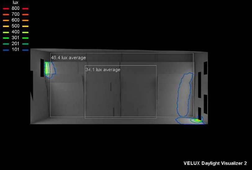
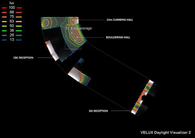
Using VELUX software to design, obtain average floor DF and Illuminance within Figures 31 -32. 12-month illuminance level on floor at +2m plan cut for the whole site is included in Appendix D2 together with detailed calculations in Appendix D1
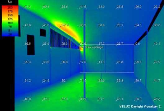
Daylight analysis of the complex using VELUX Daylight Visualizer generated from London, December mid noon conditions, light sources from glazing only. Daylighting-strategy is designed in accordance with CIBSE LG10 (2014) Guidance.
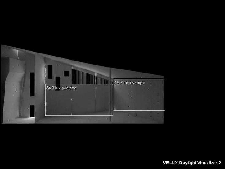
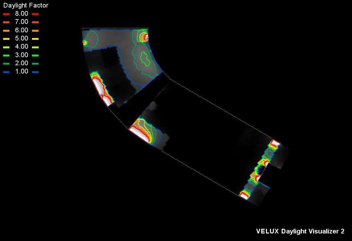 Figure 32: Average Daylight Factor an d Illuminance of the whole site at +2m plan from windows sources - December mid noon condition, London location , S15°E, generated by VELUX. Note that external pathway does n ot being included as the light source is set to be from glazing surfaces.
Figure 31: Average vertical illuminance within Bouldering area (Left), 15m climbing wall (Middle), and the interconnection section bet ween these two (Right) generated from windows sources - December mid noon condition, London location, S15°E, generated by VELUX
Figure 32: Average Daylight Factor an d Illuminance of the whole site at +2m plan from windows sources - December mid noon condition, London location , S15°E, generated by VELUX. Note that external pathway does n ot being included as the light source is set to be from glazing surfaces.
Figure 31: Average vertical illuminance within Bouldering area (Left), 15m climbing wall (Middle), and the interconnection section bet ween these two (Right) generated from windows sources - December mid noon condition, London location, S15°E, generated by VELUX
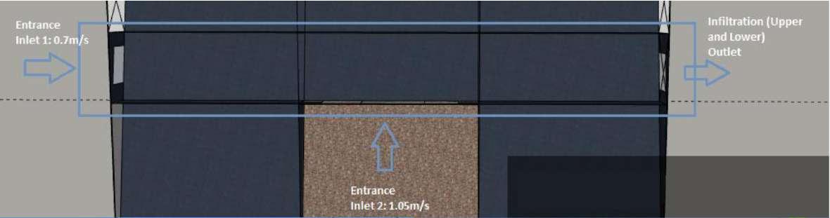
Natural ventilation possibility is assessed in accordance with CIBSE AM10 (2005) Guidance. ANSYS CFD with solar flux active mode was used for a simple computational simulation study of the Ski Reception’s temperature profile. Set up: 2 inlets of 2 entrances and 1 outlet.
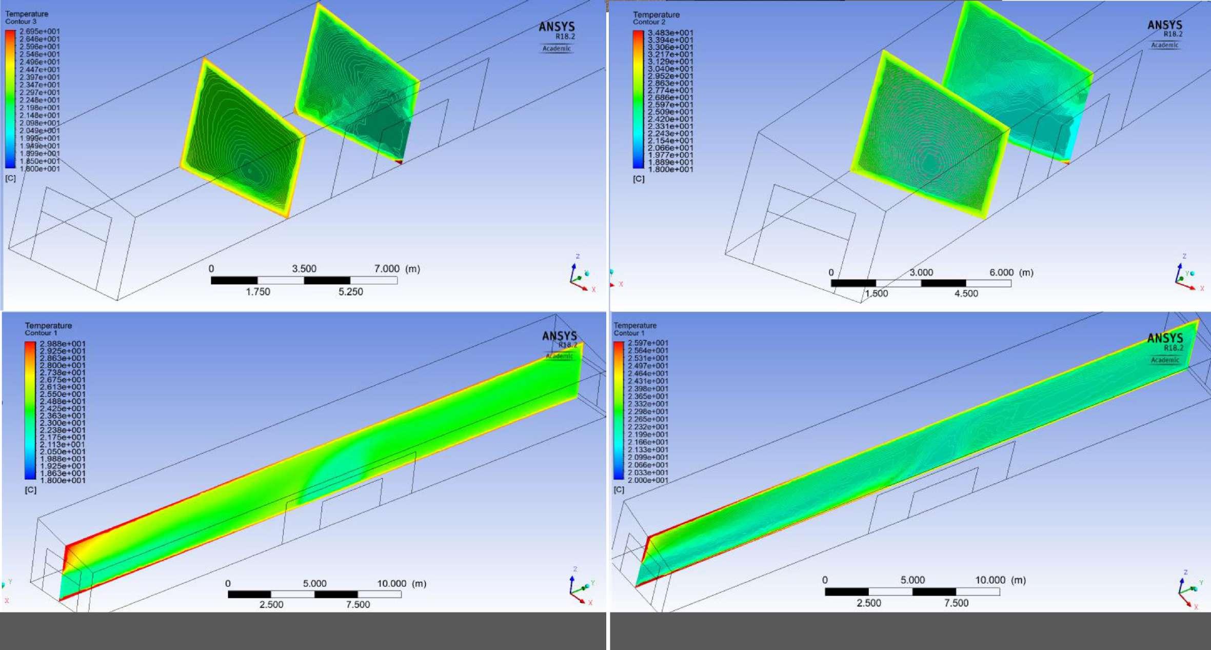
SOLAR FLUX MODE
Sheffield Summertime 22°C external temperature.
No wind - All door open (Condition 1)
Inlet 1: 0.01 m/s
Inlet 2: 0.01 m/s
Max wind – All door opens (Condition 2)
Inlet 1: 0.7 m/s
Inlet 2: 1.05m/s
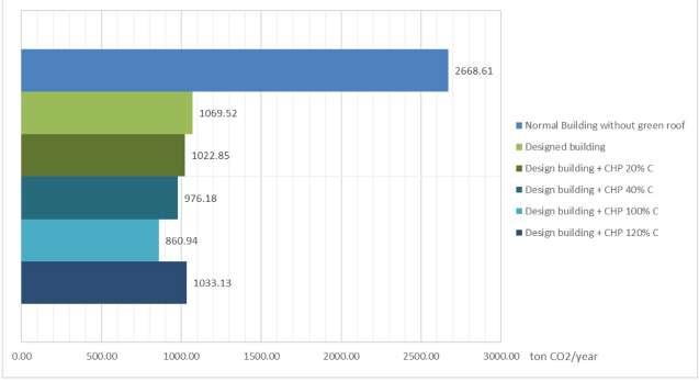
CO2 EMISSIONS BY USE (kgCO2)
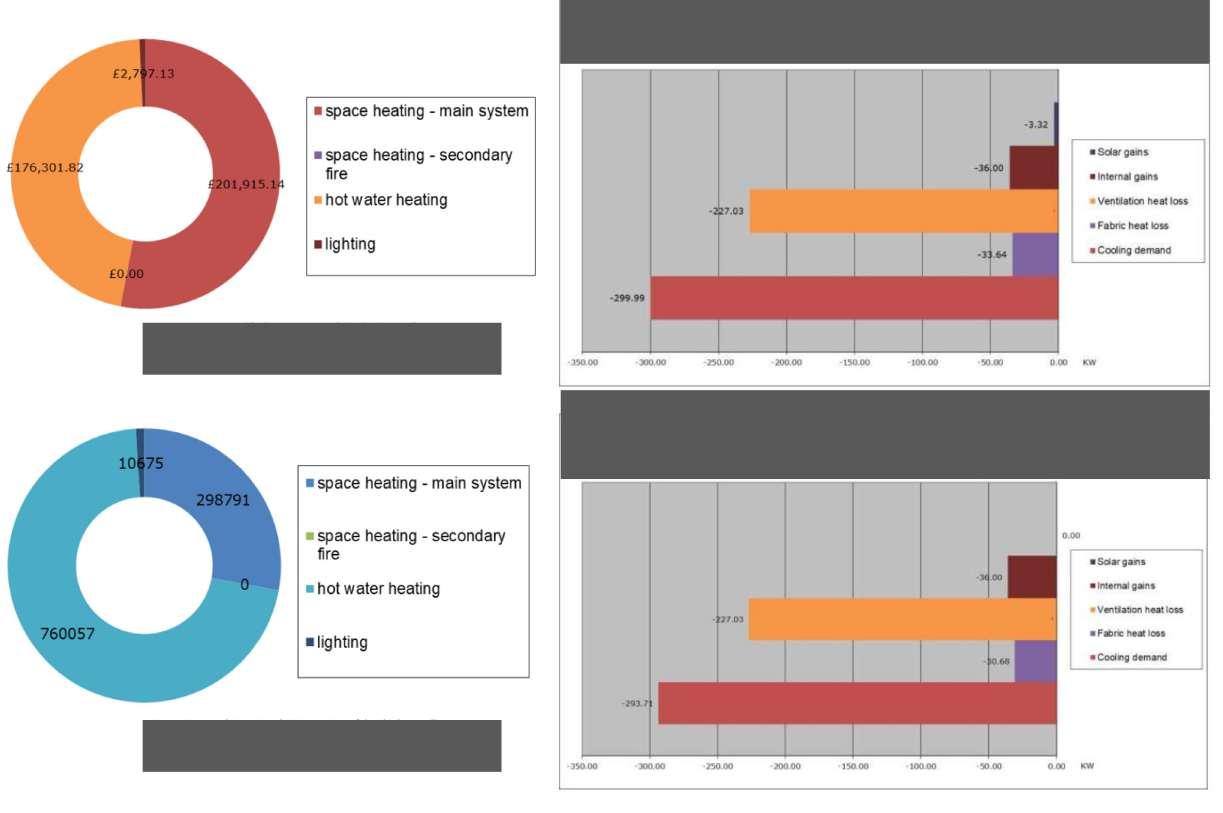
Cooling demand breakdown for the Ski Hall (where snow is). Calculated from Excel files, some based on SAP2009 energy assessment guidance.
CONSTRUCTION MATERIAL EMBODIED CARBON (tonne CO2e)
OPERATIONAL CO2 (tonne CO2/year)
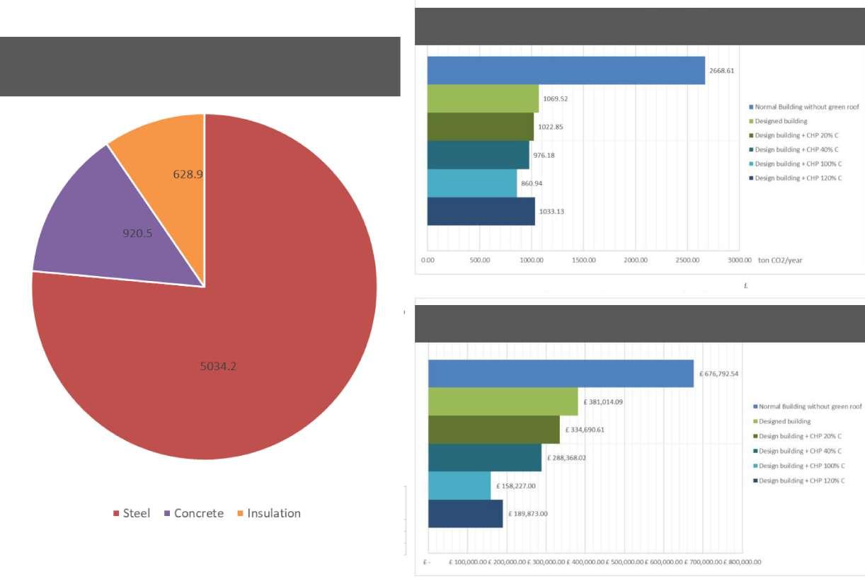
ANNUAL ENERGY COST (£)
Comparison of different building systems used for the ski hall in terms of Operational CO2 emission and annual energy cost.
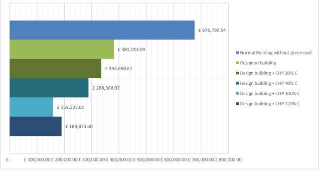
 ANNUAL FUEL RUNNING COST (£)
COOLING DEMAND BREAKDOWN FOR THE SKI HALL (kW)
COOLING DEMAND BREAKDOWN FOR THE SKI HALL WITHOUT SUN PIPE INSTALLATION (kW): no major difference identified
ANNUAL FUEL RUNNING COST (£)
COOLING DEMAND BREAKDOWN FOR THE SKI HALL (kW)
COOLING DEMAND BREAKDOWN FOR THE SKI HALL WITHOUT SUN PIPE INSTALLATION (kW): no major difference identified
Individual Project
October - December 2018
The University of Sheffield
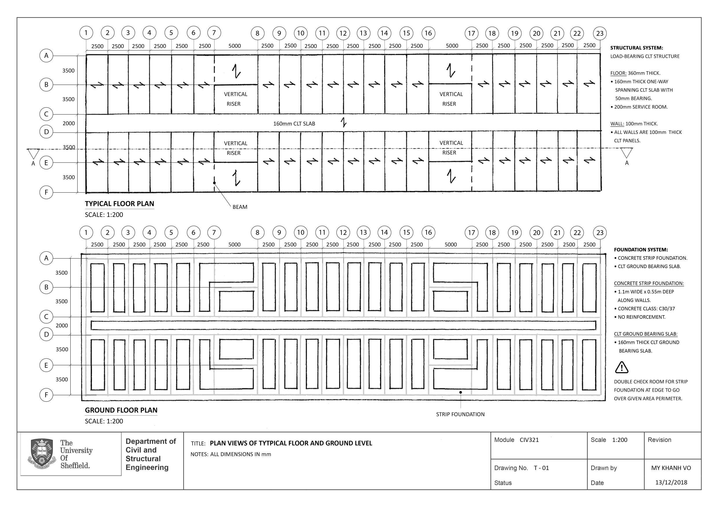
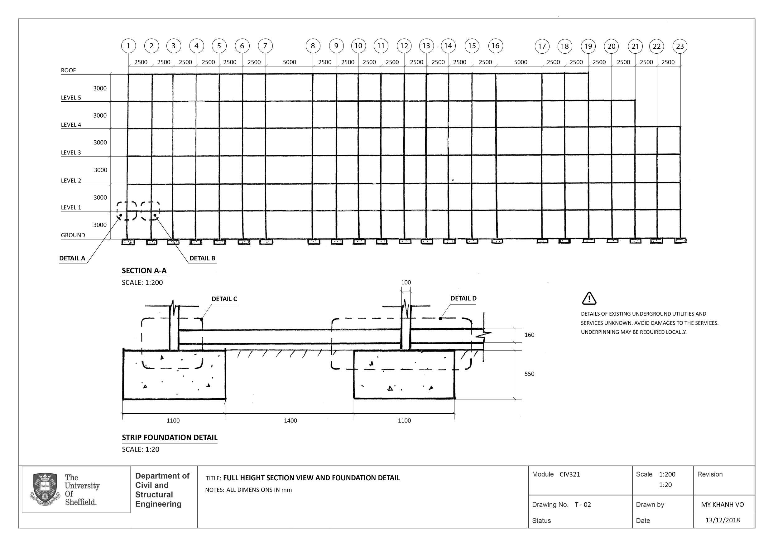
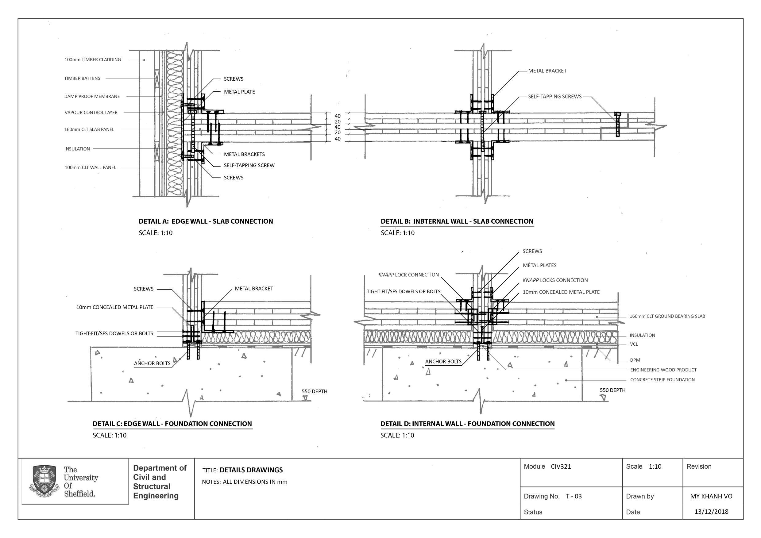
Conceptual design and calculations produced for a six-storey timber building using Cross Laminated Timber (CLT) technology and TRADA guidance. This is a duel project ran simultaneously with the other Reinforced Concrete Scheme.
Materials: Timber CLT, Concrete.
Structure:
• Timber flat roof
• CLT floor
• Load bearing CLT walls
• Strip foundation with CLT ground bearing slab.
A selection of projects presented within this section belongs to: Department of Civil and Structural Engineering - University of Sheffield Edinburgh School of Architecture and Landscape Architecture - University of Edinburgh.
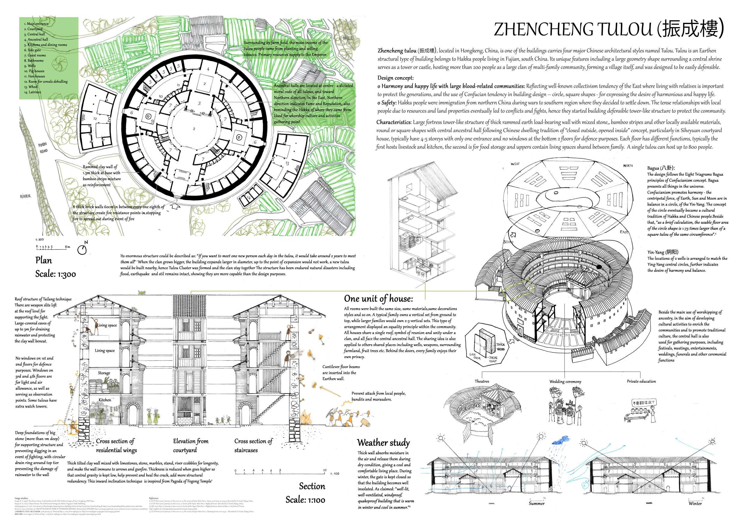
ZHENCHENG TULOU | ARC104
Dwelling study - A2 Drawing.
May 2018
The study of Tulou – one of the four main residential housing types in ancient China from structure, environmental analysis to associated socio-cultural activities and implications within the community and local society at the time.
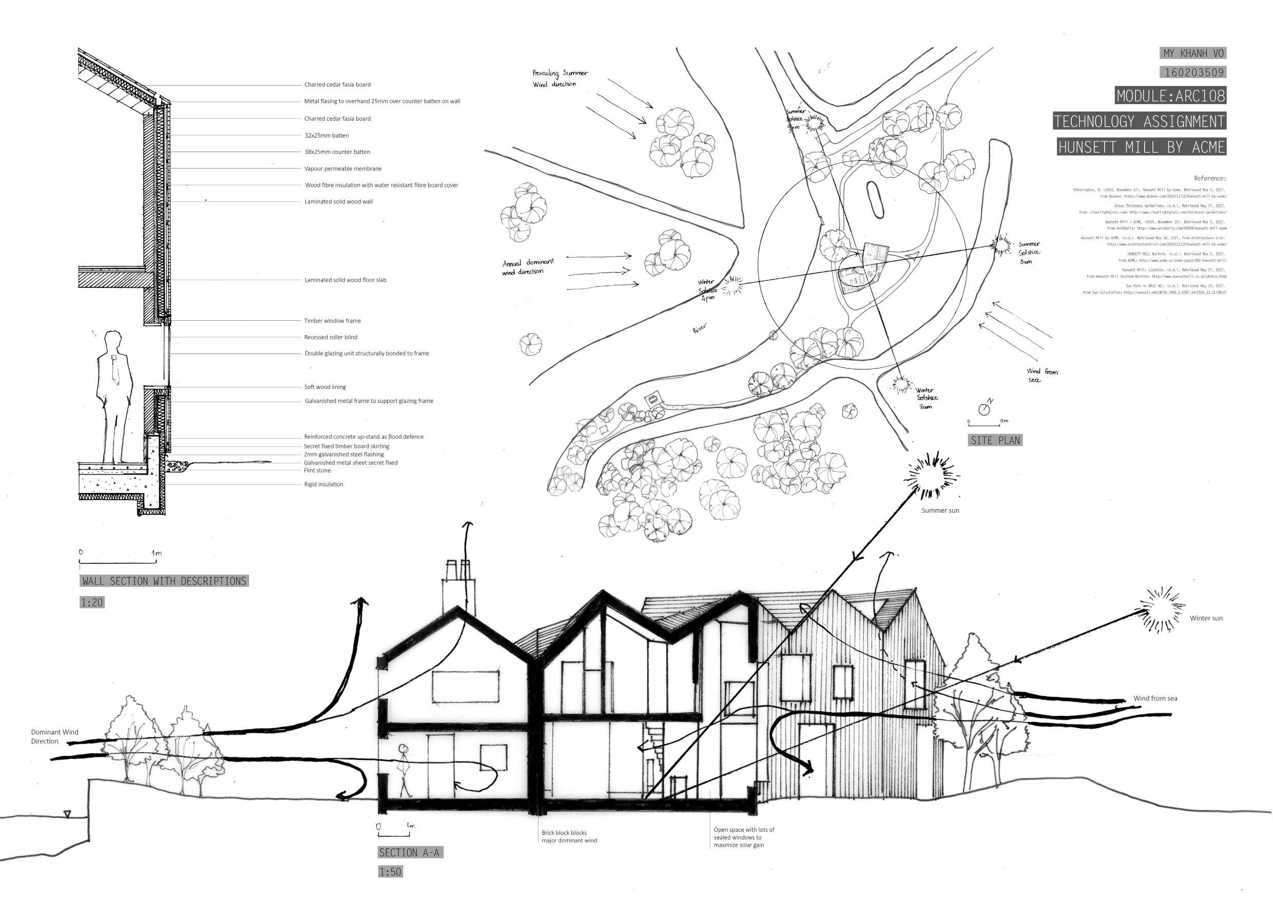
HUNSETT MILL by ACME ARCHITECTS | ARC108
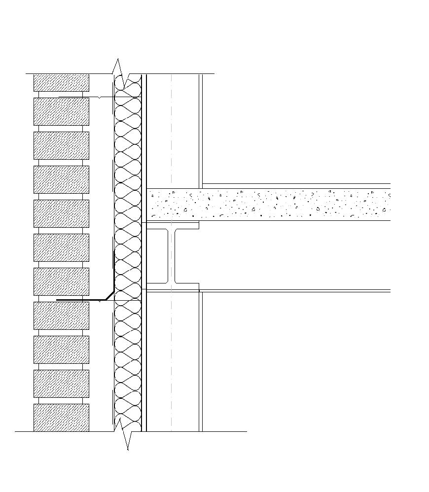
Section through a domestic scale case study - A2 Drawing.
May 2017
Examined and demonstrated the integrated approach to structures, construction materials, environmental and services criteria within a case study through an A1 minimum drawing.
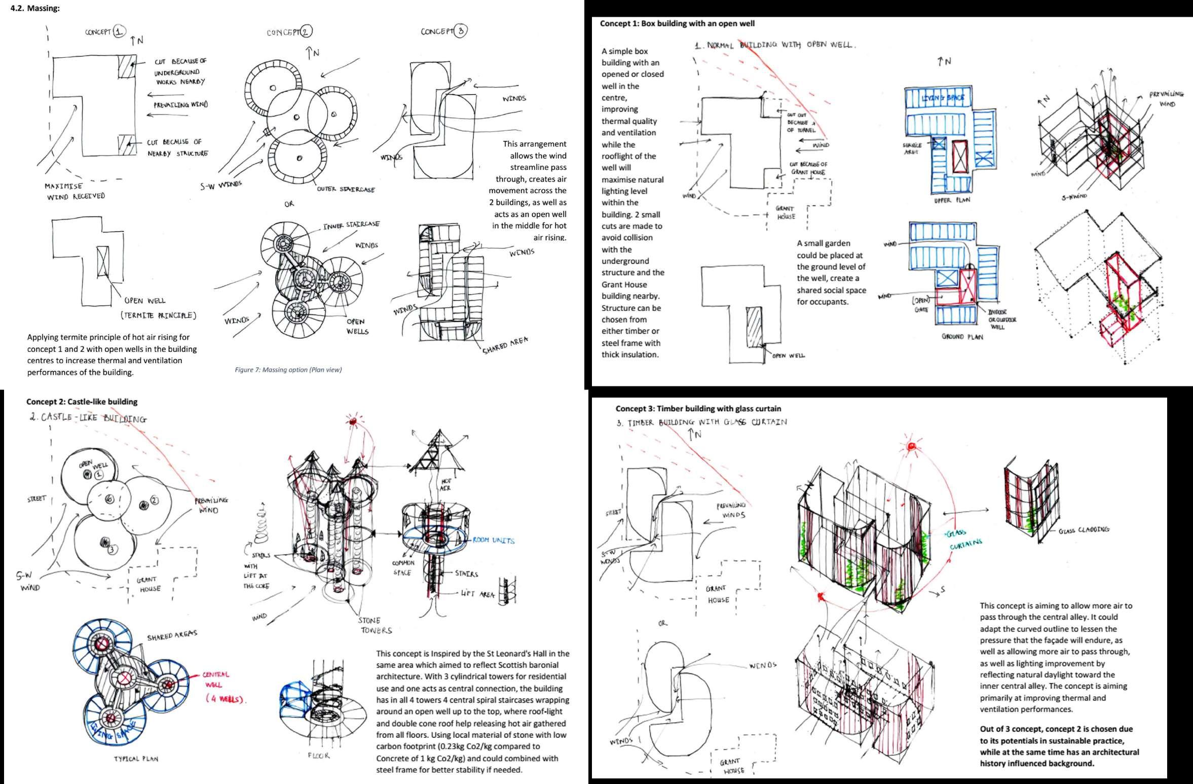
EDINBURGH’S STUDENT RESIDENCE | CIV201
Massing and 3 concept design ideas for sustainability design practice.
Feb – May 2018
Massing.
Concept 1: Box building with an open well.
Concept II: Castle-like building.
Concept III: Timber building with glass curtain.