
1.1 Appraisals: Climate & Site
1). Appraisal
Image of how the hypothetical site might look like
4. Rainwater can be harvested and reused
3) Site
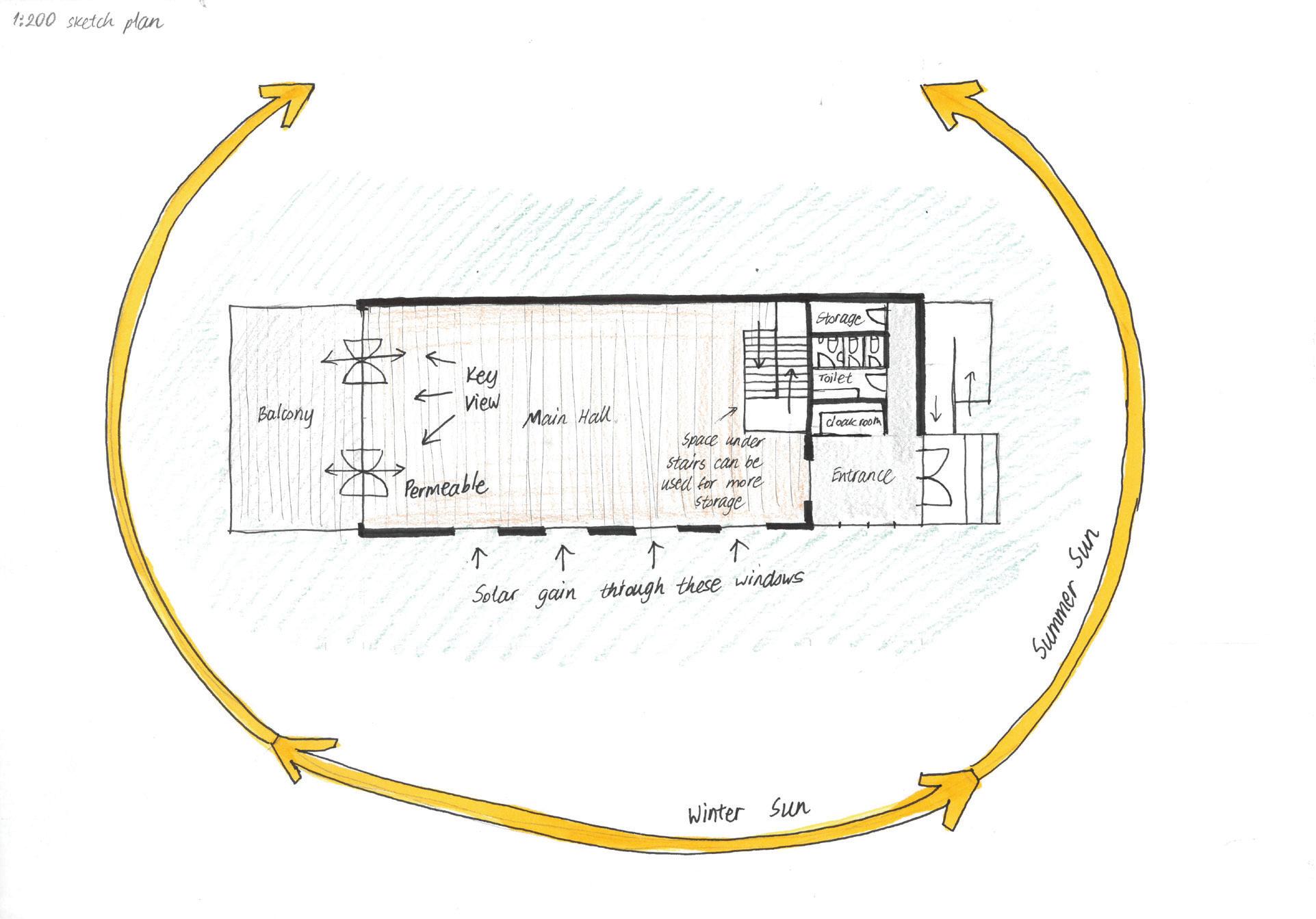
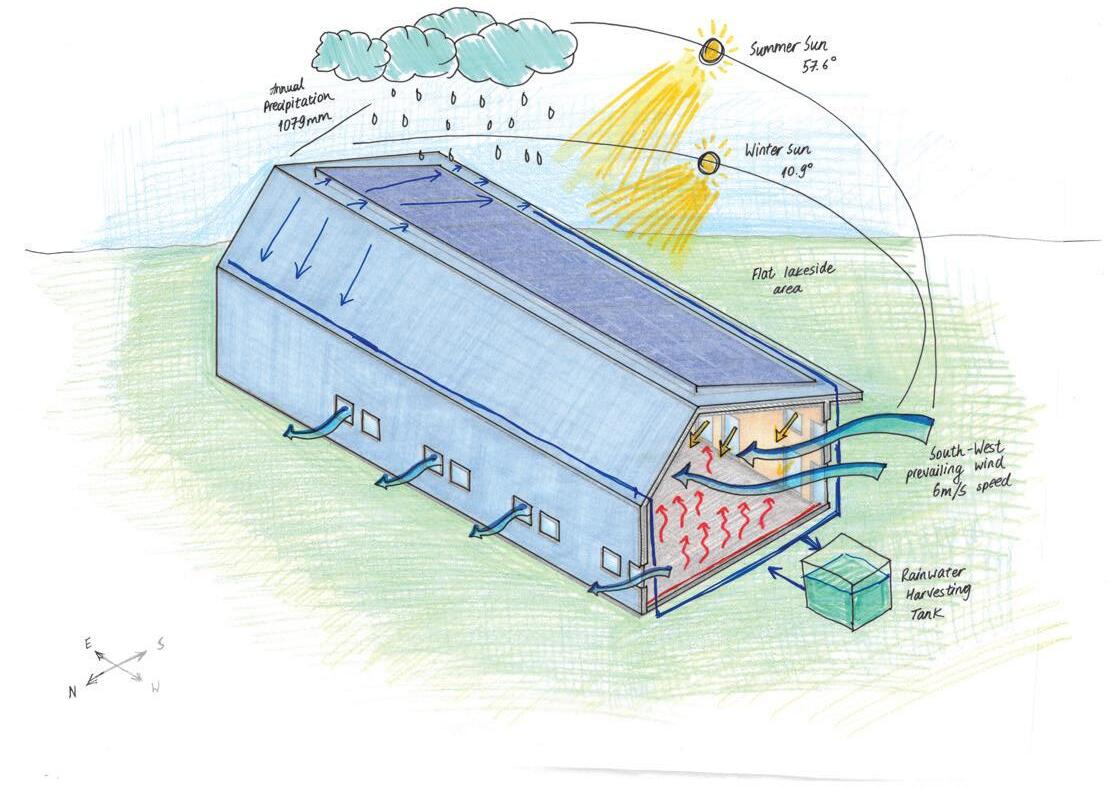
Located in a rural area of Glasgow, Scotland, the given specific site and climatic conditions state 6m/s South-West wind, lakeside flat area with negligible vegetation and East-West site orientation. My five key design drivers are:

1. Solar efficiency
+ Solar thermal gain, eliminating the need for a mechanical heating system
+ South-facing glazing
You will begin by appraising your site and climate to capture key drivers that will shape your design development over the course of the project. You will make reference to the three RIBA sustainable outcomes below in considering how best to respond to your site and climate sustainably.
+ Solar panels could be installed and work efficiently
Harvested rainwater can be used for a radiant cooling system
1. No vegetation for shading
1. The North side of the building barely gets light
1. Solar efficiency and use of electricity can be integrated via solar panels.
Annotate on a plan drawing of your building footprint all the key parameters of the site context that will be acting on your design.
3. The location is far away from everything
For each annotation, indicate the what the key parameter is and the implication it has for your design for example in terms of access and egress and general arrangement.
3. Simple, rectangular shape is adaptable for any community events
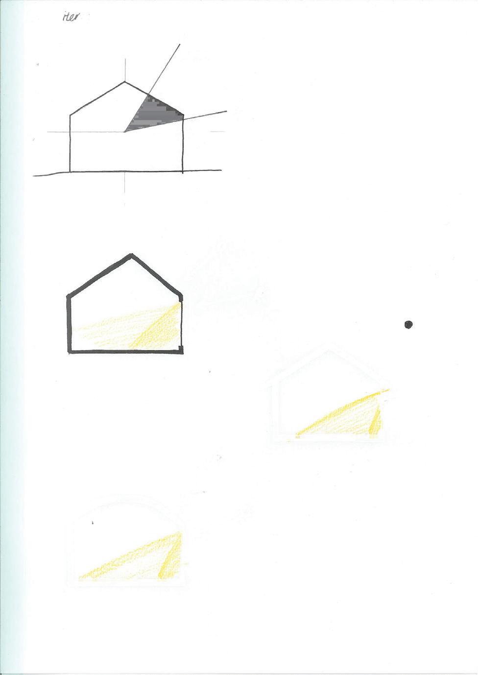
- The building could overheat as May, June, and July have the most daily hours of sunshine, rooting the need for a shading strategy
- No plants for shading
- Few daily hours of sunshine in the winter
Avoid long passages of text. Primarily use your drawings and annotations to describe your ideas. Reserve the text for evaluations.
- Shaded Northside
2. Passive ventilation
Sustainable Land-use and Ecology
+ Passive ventilation techniques with adjustable openings in the appropriate position
+ The positioning of the openings can take advantage of the dominating South-West wind
Sustainable Connectivity and Transport
+ Mitigate the use of mechanical ventilation
3. Pitched roof is useful for glazing and solar panels
5. West-facing windows needed for the main view
3. The building shape can be modified to deal with solar efficiency and wind load.


Sustainable Communities and Social Value
- Ventilation system needs to be seasonal to avoid heat loss in the winter
- Some bracing system of portal frames can be employed if the wind imposes too much lateral load
Individual Communication (Output):
3. Massing and geometry

+ Simple, rectangular shape
+ Pitched roof
+ The shape offers possibilities to implement different environmental design aspects elegantly
- The building massing is limited
Annotated drawings/ diagrams to note significant features of the location, site context and climate that could inform your design, using the three Sustainable Outcomes above as a reference for your evaluation.
- The location is far away from everything
1. Sun path causes the large glazing to be oriented South

You could use the framework of geometry, mass, light, air and water to help you think about constraints, opportunities and how your primary creative drivers may shape your
2. To avoid overheating in the summer, and for air refreshment, passive ventilation techniques can be employed
1. Use the sun to have solar thermal gain
Study Methodology:
4. Sustainable use of water and electricity
+ Evenly distributed water throughout the year
+ Rainwater can be harvested
+ Low-flow fixtures can save water used indoors
Annotate your drawings to highlight five key design drivers each for site + climate.


- Condensation risks
- Remote location, therefore limited access to electricity
For each annotation
Refer to the guidance sheet and the online references to help you with this task. Refer back to the notes from your Technologies lectures and your assignments throughout the
5. Natural views
i) Name the key creative driver.
+ Beautiful lakeside view
+ West-facing windows
+ Nice view of the sunset over the lake
- West-facing side is the narrow side of the building
ii) Annotate what specific constraints it imposes, challenges and/ or opportunities it may offer you in your sustainable design.
Use neat hand drawings to save time. Use isometric dotted paper to help your drawing accuracy.


2. Passive ventilation can mitigate the use of mechanical ventilation
1. Direct sunlight can be diffused and avoid glare via mesh, glass blocks, or jaali screens, but it will affect the view
1. Few daily hours of sunshine in the winter means that solar thermal gain may not be enough to heat the building

iii) annotate any opportunities to integrate each of the drivers with one another into a coherent and sustainable concept.
- The long face of the building will not have a beautiful view
There can be an open terrace/balcony added to the west side of the building, which also affects the massing and geometry. The building can be lifted off the ground or cantilever halfway over the lake to provide a better view and avoid the lake water entering or deteriorating the foundation/flooring.

Use this space to illustrate or annotate key climatic charac teristics that may be better communicated in small plan or

Use this space to illustrate or annotate key site characteris tics that may be better communicated in small perspective or


Comparisons and Evaluations
-Lakeside areas are more exposed and have the least shading
-Coastal areas have the most amount of wind
-Sites with low vegetation are the most suitable to employ passive ventilation
Annotate your drawings to highlight where it may be possible to incorporate a minimum of three design principles for each of the three outcomes listed above. Note that not all principles will be relevant to this specific project.
-Forests are the most shaded from the wind and sun
A table of sun angles for your site may be useful to refer to
-Lakeside and grassland have nothing surrounding to obstruct view
Comparisons & Evaluations
-North-South orientation has the advantage of receiving the widest spectacular scenery
-East-West orientation receives the most amount of direct sunlight from South, affecting the amount of glazing on different faces
-NE-SW and NW-SE both get scenery view on two sides of the building
Review the different combinations of site, climate and systems in your group and briefly note how their constraints and opportunities impact differently on your respective designs and any particular challenges this poses. These are a small but critical part of your study.
Do not attempt to re-present a large amount of generic data from published sources. Use your very early building con cept as the vehicle to illustrate this information. This will be useful to highlight your design constraints and opportunities.
- Generally cool temperature with no rapid changes throughout the year (Oceanic climate- Cfb)
- No need for seasonal adaptations
- Small amount of thermal need
- Suitable for passive ventilation
4. - Evenly distributed water throughout the year
- High humidity causes condensation risks
- Thermal comfort could be affected by the humidity
5. - Beautiful lakeside view with no disturbance
- West-facing side is the narrow side of the building, so it’s difficult to have a wider view
Manchester School of Architecture BA Hons Architecture- Technologies Unit Handbook: BA2 Part C- Technologies Design Project.
Week 1
Annual temperature graph Annual precipitation graph Prevailing wind direction and speed Sun path diagram Site key characteristics Annual daily hours of sunshine
1.2 Environmental Strategies - Massing, Form, Arrangement
2) Annotated Drawings (1:200)


Section

Drawing together your knowledge from your climate, site and systems ap praisals, quickly sketch your building. You should have plans as a minimum but ideally isometric drawings and sections to best communicate the spac


Initial programme bubble diagram
Initial
Begin with the ‘big moves’ such as the ancillary location and entrance points before moving into the detail of the planning.
See this drawing as a starting point rather than a perfect solution. Note down things that might not be working yet and may require more attention.
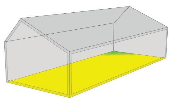
Roof glazing was eliminated because it mostly entered direct summer sunlight, which may cause over heating
Solar panels help generating clean energy for the entire building
Glazing size and arrangement will probably change due to structural system.
1. Easy access to the building
+ Open lakeside site makes it easier to locate the entrance
+ Immediately sees the hall and key view when entered
+ Access point works nicely with the building programme and massing
- The stairs need more configuration in the future
Annotate your drawings to highlight how the following drivers may shape your design (massing, arrangement, planning).


2. Space flexibility
+ The main hall can be used for a variety of events, such as public dance, church gatherings, charity events, weddings, and other ceremonies.
+ Thermal comfort and ventilation provided for different activities

- Access, egress, circulation
- Required arrangements should be made before the events
- Safety considerations
3. Interior and exterior visual comfort
- Lighting quality
+ Well lit interior with thermal gain
- Air quality/ ventilation
+ Soft looking timber internal finish
- Spatial quality, views, sequence
+ Exterior look blends pleasantly with the surrounding
+ Draws attention to the spectacular view
- Building might disrupt the lake view from a certain point of view
For each annotation
This iteration was chosen because of the maximisation of the South-facing roof area
i) Name the key creative driver.
4. Community engagement
+ Inclusive space for everyone
+ Safe space for a variety of people and events
- Might get overlit for some specific events
ii) Annotate what specific es, challenges and/ or offer you in your sustainable design.
5. Services and additional spaces
(Thumbnail Plans and Isometric Strategy Diagrams as appropriate)
I found it better to keep the simple form of the building than massively change it for the sake of aesthetics. The rectangular pitched form works well with the environment, programme, and structure.
+ Cloakroom, gender-neutral, accessible toilets, and storage room
+ Low fixture toilets, LED lights to save power and water
+ Mezzanine area for meetings, projection, and supervision
iii) annotate any opportunities to each of the drivers with one another into a coherent and sustainable concept.
Comparisons and Evaluations
Annotate your drawings to highlight a minimum of three design principles for each of the three RIBA Outcomes listed above.
Iteration 3: North-East entranceBarely receives light
Iteration 5: South-East entranceReceives good light, good privacy
- The entrance position and ancillary space are highly dependent on the orientation given
- Additional spaces to the main hall vary according to different programmes. Some buildings need bars, a kitchen etc.
Comparisons & Evaluations
- Window sizes and positions differ across the group depending on the orientation, key view, and wind speed
Compare how the design constraints and op portunities differ across the respective allocations of your group.
Iteration 2: North entrance- Dark, doesn’t directly see the main hall
Iteration 4: East entrance- Directly enters the main hall, small light, little privacy for the toilets
Iteration 6: South-East entranceDirect entrance, storage room added, good privacy, good amount of sunlight
Manchester School of Architecture BA Hons Architecture- Technologies Unit Handbook: BA2 Part C- Technologies Design Project.
Week 1
1:200 plan and elevations
- Mezzanine is considered to be a very useful area iteration regarding sun angle 1:200 Ground floor plan 1:200 First floor plan Plan iteration
Iteration 1: South entranceSusceptible to prevailing wind
1:200 Section
1:200 Isometric view of the building
The staircase occupies quite a lot of space, which needs further attention
Initial outside sketch
Initial design sketch
1.4 Initial Integrative Building Concept
1) Summary: Personal Response
Based on your preceding appraisals. This initial concept should embody and reflect the contextual drivers of the site and climate acting upon it as well as the constraints and opportunities offered by the materials and systems you are employing in the design.
It should also be evident in your drawings how your design responds to the social and environmental responsibilities you have as an architect. Annotate these in your sketches of your overall concept so that it is explicit. Use the language of the RIBA Sustainable Outcomes design principles.
2) Annotated isometric or perspective view.


Guidance Tips
Summarise graphically through annotated drawings how you have integrated and synthesised your ap praisals and arrived at an initial design concept.
South-facing glazing’s positioning changed according to the portal frames. Instead of double height windows, there are two separate windows for each column for ease of access and operability.


Try to use all the drawing conventions you are aware of to neatly annotate your drawings by hand or with a computer, including reference bubbles, call outs and leaders for annotation, show referenced cut lines, grid lines, floor levels, key datums and other setting out information with dimensions.
I’m aiming for triple glazed windows for better insulation.
Indicate a person in your spaces for scale.
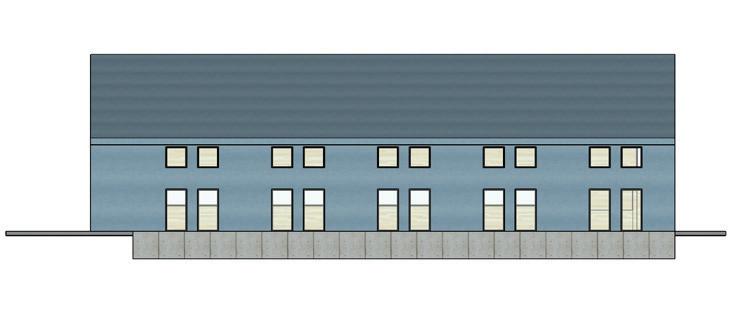
Annotated Key Elevation Drawings (1:200)
Individual Communication (Output):
The initial design responds to the climate, site context, and client needs in a community engaging and sustainable way. As the design stage is early, there will be further development and exploration of the programme, structure, material, and construction methods. The building uses steel portal frames as the primary structure with reinforced concrete raft foundation, aluminium cladding, and sheep’s wool-based insulation.
Personal position regarding sustainability as the architect:
1. Net zero carbon
Annotated drawings/ diagrams of your overall concept. These will be more developed than the earlier strategic plans and massing/ arrangement studies. This page establishes the design you will test and develop in Week 2 before focusing on the detail design study of your envelope in Week 3.
Use published drawings as examples to help. Use at least two line weights for section drawings (thin and thick) to indicate what is cut through and what is seen in elevation.

Annotated Typical Section Drawing (1:200)
Annotated Typical Section Drawing (1:50) (Cut through the key elevation).

Prioritising the use of locally and ethically sourced local materials, efficient and environmentally friendly construction methods (in this case, steel prefabrication and on-site assembly,) and low energy appliances. Providing a long-lasting, robust community hall with responsive local controls.


Study Methodology:
Annotate your drawings following the guidance adjacent to suit your design. The design will be unique to your own attitudes, approaches and priorities for design.
2. Responsible land use
Emphasising the construction methods with the least land disruption. Retaining existing land creatures and vegetation. Minimising the pollution caused by the construction process and encouraging land and building re-use.
3. Passive environmental strategies
Providing solar thermal gain, passive ventilation, and passive cooling techniques to avoid the excessive use of mechanical services that require energy.

Include five bullet points here that explain your personal position regarding sustainability in architectural design and technological realisation in general and note how it is manifest in your specific design. How is your design exemplary.
4. Regenerative building
Promoting the use of rainwater and greywater recycling systems alongside low fixture toilet appliances. Generating the necessary electricity from the south-facing solar panels for the low energy lights and other features.
Comparisons & Evaluations
Compare how the designs differ across the members of your group at the end of Week 1 (in relation to the different allocations of site, climate and materials).
5. Social values for the community
Creating an inclusive and safe space for everyone to engage with their communities. Providing the building users with thermal, air, visual and acoustic comfort for various activities.
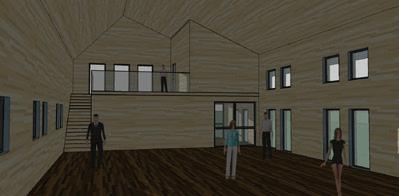
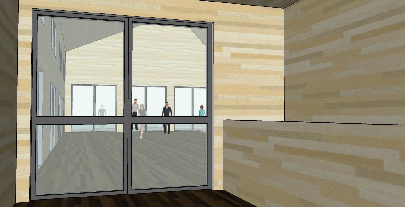
Thumbnail interior and exterior views at eye level
Comparisons and Evaluations
- Construction type and process varies across the group depending on the different structural and cladding system using
Use neat hand drawings to save time. Use isometric dotted paper to help your drawing accuracy and/ or use a screen grab of your digital model to trace over.
- There are discussions about more sustainable alternatives to a concrete foundation (hempcrete, concretene, or helical screw pile)
- Solar strategies of the whole building change due to the orientation
- There are different types of solar shading devices being used across the group, which I need to research to decide whether my design needs or not

19 November 2021 Manchester School of Architecture BA Hons Architecture- Technologies Unit Handbook: BA2 Part C- Technologies Design Project.
Week 1
Ground
plan Main Hall Outdoor deck Entrance hall Main hall Meeting room Mezzanine Cloak Toilet Storage First
plan
floor
floor
Solar panels for regenerative energy RC foundation
North face of the building has noticably less amount of glazing
The building is slightly lifted, so there is a ramp for wheelcahir users
Aluminium cladding
Entrance glazing
Operable glazing
Main glazing for the key view
Outdoor deck
South elevation North elevation West elevation East elevation Section cc Section dd Section
Section bb Portal
a b b c c d d a
aa
frames
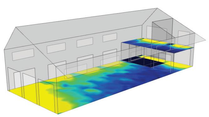
2.1 Iterative Testing - Environmental Performance: Glazing Amount
1) Quantitative Testing
Iteration 1 - (Benchmark 100%)
Proposed test:
Amount of glazing = 100%
Amount of glazing = 50%
Amount of glazing = 20%
Expected results:
You will now test your design quantitatively through digital simulation and improve the performance in daylighting and energy by considering parameters of your glazing design, initially the amount of glazing.

- I’ve chosen the suggested parameter values as they are even and logical numbers
Use the project specific Sefaira instructions on Moodle to set correct units and climate conditions). Your units should be metric and lux, not Btu and
Parameter Values
Glass U-value = ? W/m2K
Wall U-value = ? W/m2K
Glazing : wall ratio = 100%
Performance Results
Intensity Value Check: (kWh/m2/yr) Target ? Actual ?
Performance Results
Energy Load (kWh/yr)
- Iteration 1 having full glazing and being the worst-case scenario, it will be overlit and have the highest energy load
- Although it’s the worst-case scenario, iteration 1 sets the benchmark for the remainder of the test
- Iteration 2 will have considerably fewer energy demands and the light amount
Individual Communication (Output): Tabulate your findings from Sefaira in the table adjacent (replace the text in red with your own values and results). Show thumbnails of your design model.
- Iteration 2 might still be overlit and energy heavy, but the problem can be solved with solar shading devices
Glass : distribution (as drawn)= ?
Gains + Losses Comment:
Lighting ? Heating ? Cooling ?
Daylighting
Under lit ?% Well lit ?% Over lit ?%
Study Methodology:
- Iteration 3 will be either underlit or balanced, but it will be the most energy-efficient
- Despite being energy efficient, it will have the constraint of minimizing the nature view
Parameter’s disclaimer:
Summarise your quantitative tests following the headings below for the amount of glazing. For your first iteration (benchmark) assume your design has 100% glazing to establish a worst case performance (i.e. it will be overlit with high energy demand for heating).
Iteration 2
Glazing conduction has the highest level of heat loss. South solar gain is the greatest out of the four directions, but the amount is less than expected. Impact on heating is much more than the impact on cooling.


Parameter Values
Glass U-value = ? W/m2K
Performance Results
Performance Results
Proposed Test:
To only test the effect of glazing amount, U values and other parameters, such as equipment, lighting, solar heat gain coefficient were kept at the same value. The Glazing U value was set to 1 pane (5 w/m2k) as instructed by the guidance document. For iterations 2 and 3, all the glazing is placed on the South and Westside, while maintaining the glazing to solid wall ratio.
Parameter Test - Glazing Amount (Evenly)
Observed results:
Wall U-value = ? W/m2K
Energy Load (kWh/yr)
Amount of glazing = ?% (e.g. 100%)
Amount of glazing = ?% (e.g. 50%)
- As expected, iteration 1 had the worst performance in terms of energy use and daylight distribution
Glazed wall : solid wall ratio = ?:?
Glass : distribution (as drawn)= ?
Intensity Value Check: (kWh/m2/yr) Target ? Actual ?
Lighting ? Heating ? Cooling ?
- Iteration 2 had less energy demand and daylight, but the numbers were higher than expected
Amount of glazing = ?% (e.g. 20%)
- Iteration 2 had almost the same daylight distribution as iteration 1 despite having 50% less glazing. This was due to the glazing orientation.
Expected Results
- The elimination of North and East glazing had a very small effect in daylight but a significant effect on energy use
- Iteration 3 was the best performing one, but still didn’t reach the target
- Iteration 3 was mostly overlit as opposed to the expectation
State why you chose the parameter values and what you expect to happen to the lighting levels and the energy loads when you adjust the parameters for each of the studies above.
- There was no disruption on the natural view as the West glazing remained the same throughout the testing
Observed Results
- All three iterations were energy heavy and overlit, but there was a noticeable improvement throughout
Despite the elimination of North and East glazing, solar gain is still the same. Loss in heating through glazing is the highest. Loss in heating and cooling are both greater than the gain. The impact on heating is still greater than the impact on cooling. Although energy need is reduced, it still doesn’t reach the target.

Daylighting
Under lit ?% Well lit ?% Over lit ?%
- Most of the energy load is on heating
What happened? How did the performance actually change? Did improvements to one performance criteria act to the detriment of the other?
Conclusions
- I suspect the poor energy performance is not only because of the glazing amount but also the U value of the glazing
Conclusions
- As I’m aiming for a Passivhaus standard, insulation and glass U value should be higher for further tests
Iteration 3
Parameter Values
Glass U-value = ? W/m2K
Performance Results
- More detailed glazing amount and distribution should be tested further
- Solar shading techniques, such as external blinds, or roof overhangs need to be considered


- The iterations made me realize that the glazing amount should be reduced for better energy and daylight performance
- Interior walls and foors should be added for better clarity
What would you test next to improve overall performance. Do you need to make any tradeoffs between the parameters? Does the relative change in the performance values for each test make sense? Do the numbers themselves make sense?
Comparisons and Evaluations
Ensure you have the correct
Wall U-value = ? W/m2K
Glazed wall : solid wall ratio = ?:?
Glass : distribution (as drawn)= ?


Energy Load (kWh/yr)
Lighting ? Heating ? Cooling ?
Daylighting
Comparisons & Evaluations
-Solar gain and energy performances differ depending on the orientation
-Due to the small exposure to South, North-South orientation generally perform worse than the other orientations
-NW-SE orientation buildings resist wind load the best
-Regardless of the orientation, larger glazing with high U-values always resulted in poor energy performance and was overlit.
Compare your performance results for your design in its context with the others’ in your groupwhat aspects of your design’s performance would differ or are better/ worse by being in your context/ orientation. Be specific and concise.
Loss in heating through glazing induction is reduced but still high. The solar gain amount is also reduced due to the smaller amount of glazing. In general, glazing has much more impact on heating than cooling. Wall conduction heating loss is greater than expected. Roof conduction also has a significant amount of heat loss.
Under lit ?% Well lit ?% Over lit ?%

19 November 2021 Manchester School of Architecture BA Hons Architecture- Technologies Unit Handbook: BA2 Part C- Technologies Design Project.
Losses Comment:
Gains +
Target
Actual
Losses Comment: Week 2
Performance Results Intensity Value Check: (kWh/m2/yr)
?
? Gains +
5 W/m2K 5 W/m2K 5 W/m2K 0.26 W/m2K 0.26 W/m2K 0.18 W/m2K Roof U-value = 0.26 W/m2K 50:50 20:80 95 95 95 224 169 147
6811 6811 6811 36294 23207 18663 1297 1190 892 0 0 0 0 9 25 100 91 75
0.18 W/m2K Roof U-value = 0.18 W/m2K Roof U-value =
2.2 Iterative Testing - Environmental Performance: Glazing Distribution
1) Quantitative Testing
Iteration 1
Proposed test
Iteration 1: Evenly spaced 20% glazing on West and Southside with West shading
You will now test your design quantitatively through digital simulation and improve the performance in daylighting and energy by considering parameters of your glazing design, here, the distribution of glazing.


Iteration 2: South and West reduced, North and East increased, South overhang Iteration 3: Evenly distributed smaller windows, West shading, and South overhang
Use the project specific Sefaira instructions on Moodle to set correct units and climate conditions). Your units should be metric and lux, not Btu and
Parameter Values
Glass U-value = ? W/m2K
Wall U-value = ? W/m2K
Glazed wall : solid wall ratio = ?:?
Performance Results
Intensity Value Check: (kWh/m2/yr) Target ? Actual ?
Performance Results
Energy Load (kWh/yr)
Individual Communication (Output):
Expected results
Glass : distribution (as drawn)= ?
Lighting ? Heating ? Cooling ?
- The parameter values are chosen to investigate the change in the distribution of glazing and shading strategies on the lighting levels and energy loads
- Iteration 1 might be overlit and exceed the target energy load.
- West shading will affect West heat gain
Tabulate your findings from Sefaira in the table adjacent (replace the text in red with your own values and results). Show thumbnails of your design model.
- Iteration 2 might have more balanced daylight but the North and East gains are not very promising
Gains + Losses Comment:
- South overhang will reduce the daylight amount
Study Methodology:
- Iteration 2 energy load will be greater than iteration 1, probably due to the increased amount of glazing on the Northside
- Iteration 3 will be more energy efficient
Summarise your quantitative tests following the headings below for the distribution of glazing.
- Iteration 3 window dimensions need a careful consideration
Loss in heating through glazing is significantly decreased. South solar gain is the greatest and North solar gain is non-existent. Heating loss is still greater than cooling but it has decreased compared to the data on the previous page.

Daylighting
Under lit ?% Well lit ?% Over lit ?%
Iteration 2
Parameter’s disclaimer
Be careful not to change multiple parameters simultaneously as this will make it difficult to determine what is affecting the performance.
For more accurate and realistic results, the glass U value was changed to 1.6 from 5. Part L default properties values are used for the iterations, however, to achieve the Passivhaus standard, U values need to be less than the default values.
Proposed Test:
Observed results
Parameter Test - Glazing/ Wall Distribution
- As expected, iteration 1 was overlit
Parameter Values
Glass U-value = ? W/m2K
Wall U-value = ? W/m2K
Performance Results
Performance Results
Energy Load (kWh/yr)
Distribution of glazing = ? (e.g evenly)
- Surprisingly, iteration 1 reached the energy load target
Glazed wall : solid wall ratio = ?:?
Intensity Value Check: (kWh/m2/yr) Target ? Actual ?
Distribution of glazing = ? (e.g. south reduced)
- West shading wasn’t that effective, but it is still useful for sheltering the South façade and deck from snow and rainfall
Glass : distribution (as drawn)= ?
Lighting ? Heating ? Cooling ?
- I was pleased with the daylight results of iteration 2
- Iteration 2 energy performance was reduced because of the glazing orientation, but now by a large amount
Distribution of glazing = ? (e.g. regular pattern..) (Your screen grabs will be most useful here in showing the distribution of glazing).
- Iteration 3 had the best overall performance
Gains + Losses Comment:
Expected Results
- Iteration 3 daylight distribution was even, and the amount was balanced
- Iteration 3 smaller windows at the suitable height are more accessible, operable, and provide sufficient daylight


- South overhang of iteration 3 worked well with both winter and summer sun
- All 3 iterations reached the energy load target
State why you chose the parameter values and what you expect to happen to the lighting levels and the energy loads when you adjust the parameters for each of the studies above.
- With the iterations on this page, energy load on heating is remarkably reduced, but the lighting energy load is slightly increased


Observed Results
Conclusions
Iteration 3
Loss in heating through wall conduction remains high, so the insulation needs to be better. Loss in heat through glazing conduction is greater than iteration 1. This is because of the increased amount of North glazing and decreased amount of South glazing.

Daylighting Under lit ?% Well lit ?% Over lit ?%
- Solar shading techniques need further research as it affects the building geometry and structure
What happened? How did the performance actually change? Did improvements to one performance criteria act to the detriment of the other?
- Triple-glazed windows, thicker insulation, and low energy heating systems will increase the building performance
Parameter Values
Glass U-value = ? W/m2K
Performance Results
Performance Results
- U values have more effect on the building energy, and changes in glazing amount, pattern, and orientation have more effect on the daylight
Wall U-value = ? W/m2K
Conclusions
- Relative change in values and result numbers made a good sense
Comparisons and Evaluations
-Including the internal walls resulted in more accurate results and glazing distribution


-There are discussions about implementing different solar shading devices across the group
What would you test next to improve overall performance. Do you need to make any tradeoffs between the parameters? Does the relative change in the performance values for each test make sense? Do the numbers themselves make sense?
-Glazing amount has decreased reasonably across the group (2025% glazing was dominantly preferred)
Date and time (Mar 21st, 9am)
Glazed wall : solid wall ratio = ?:?
Glass : distribution (as drawn)= ?
Intensity Value Check: (kWh/m2/yr) Target ? Actual ?
Gains + Losses Comment:
Energy Load (kWh/yr)
Lighting ? Heating ? Cooling ?
Daylighting
Under lit ?% Well lit ?% Over lit ?%
-NE-SW and NW-SE orientations have better and more balanced daylight performance
Comparisons & Evaluations
As previously, compare your performance results for your design with the designs in your group.
-Sefaira testing on day 2 had a more determined effect on the building design than day 1
South solar heating and cooling gain are added as the Southside glazing is increased. North solar gain is the least despite having the longer side of the building. The majority of the heat loss is via conduction, therefore higher insulation performance and the use of triple-glazed windows can thermally seal the building for better energy efficiency.

19 November 2021 Manchester School of Architecture BA Hons Architecture- Technologies Unit Handbook: BA2 Part C- Technologies Design Project.
Week 2
1.6 W/m2K 1.6 W/m2K 1.6 W/m2K 0.26 W/m2K 0.26 W/m2K 0.26 W/m2K 20:80 30:70 24:76 95 95 95 87 89 88
8173 8173 8173 5466 6148 5798 924 891 896 12 23 22 34 64 54 54 13 24
0.18 W/m2K 0.18 W/m2K 0.18 W/m2K Roof U-value = Roof U-value = Roof U-value = Daylight factor Daylight factor Daylight factor
and time (Mar 21st, 9am)
Date
Date and time (Mar 21st, 9am)
2.3 Iterative Testing - Environmental Quality: ‘Spatiality’ + Materiality


1) Qualitative Testing
Alongside testing the quantifiable performance
Interior + Exterior Perspective Views


Drawings and renders of spaces at different times of the day, from the same view point can sometimes be very effective at clearly showing how the space is used differently and lit differently. Laying these out in a uniform way will evidence a structured and rigorous approach to your design development.
these other features of your design.
I improved the floor plans to include a kitchen and have a better staircase positioning.
This builds on your qualitative testing in Papermetrics last year.
Interior visual comfort is provided by Scottish larch timber cladding. The Interior has a soft natural finish, which works in harmony with the sunlight coming through the South-facing glazing without causing any glare problems. Timber interior is suitable for any type of activity and event. Steel frame windows can offer a wide range of sizes and provide an extensive view of nature.
Individual Communication (Output): Communicate the interior and exterior qualities of your building on this page through views inside and around your building (from eye level).

Steel frame, insulation, and other fixing elements are not visible from both outside and inside. Both exterior and interior of the building are clean, minimal, and modern. Kingspan’s dri-design aluminium cladding in soft blue colour creates an exterior look that blends elegantly with the adjacent lake.


Study Methodology:
Use annotated drawings and images, that explain what each of the materials and elements are and how their characteristics contribute to creating your environment and spatial quality.
From observation of the interior and exterior shadow study, the building is pleasantly shaded from the summer sun and receives a good amount of winter sun. West glazing needs outside operable blinds to prevent the evening sun, but the South glazing only needs internal ones, since the overhang provides enough shading.


E.g. shiny, hard, soft, heavy, transparent, translucent, colourful, etc and relate these to the effect they will have e.g. to control the acoustic, the lighting quality, views etc.
During the day, the building receives a sufficient amount of natural light, making it suitable to host events like charity or community gatherings. During the night, dances, movie screenings, and formal dinners can be held.
Think about the activities you will accommodate at different times of day and times of the year and the qualities they require and illustrate these different scenarios. Light, dark, enclosed, covered, semi-external, external...
Use a camera/ view point at eye level, looking horizontally to capture an accurate represen tation of the space. Include people to indicate
Consider key views of the exterior, at thresholds looking inside and at thresholds looking out. Think about the views and how you frame them in your glazed openings.


Timber cladding


Scottish larch internal cladding and flooring are used to create a warm and soft interior look. Despite Scottish larch being a softwood, it does not require regular treatment. Flooring is much darker coloured to absorb maximum heat from direct solar gain.


Steel frame windows

For the main glazing elements, there are steel frame windows and doors. The steel frame is three times stronger than aluminium and has a much cleaner and slimmer look. It is available in a wide range of sizes and is recyclable. Although it’s more expensive than aluminium, it has a much longer lifespan.
insulation, ideal for public spaces like a community hall.


Kingspan’s dri-design aluminium rainscreen cladding provides an aesthetically pleasing look and can be installed twice as fast as comparable systems with minimum components. Possible for direct fixing or can be fixed to a rail to form a ventilated cavity. Aluminium has a long life expectancy and is very easily recycled.
The steel frame isn’t exposed internally or externally. Steel is strong in both compression and tension, can span long distances, and is endlessly recyclable. Due to its durability, recyclability, and longevity, steel can be considered a sustainable material despite its high embodied energy.

Reinforced concrete wide toe raft foundation transmits the building’s dead and live loads down to the ground. The use of raft foundation reduces the formwork and excavation costs significantly. The deeper reinforced “toe” extends to support the external side of a wall, preventing the need for a thick slab, which would be very expensive.

19 November 2021 Manchester School of Architecture BA Hons Architecture- Technologies Unit Handbook: BA2 Part C- Technologies Design Project.
Week 2
Equinox
Structural steel
Aluminium cladding
Raft foundation
Summer Winter Entrance Key view East view Ground floor ancillary View from entrance hall Mezzanine Morning Noon Evening Morning Noon Evening Morning Noon Evening Main hall Main hall Outside deck Outside deck Mezzanine Meeting room Entry Kitchen WC Ground floor First floor Elevations
2.4 Integrative Environmental Design - Tactics
Environmental strategies
1) Environmental Tactics
Building upon the environmental strategies and envelope design of week 1, this page further develops the envelope of the whole building and demonstrates different ways of active and passive strategies.
Using your environmental strategies from Week 1, together with conclusions from quantitative and qualitative testing of energy and lighting levels in Week 2, you will use this sheet to communicate your tactics as a whole assembly (developing the typical buildups and zoning con sidered in Week 1)
Alumium rainscreen cladding
- Provides weather resistant layer
- Defines the exterior look
- Fixed to a vertical support rail
Since week 1, the glazing amount and distribution has significantly changed due to the energy and daylight analysis in Sketchup and Sefaira. The skylight was considered in the earlier stage of the design process but avoided due to the disadvantages, including, disruption of rainwater collection. the complication of shading, weak thermal performance to achieve Passivhaus standard unless it is quadruple glazed, which would unnecessarily cost more.


Breather membrane
You will set out your initial design for your building envelope to deliver the performance and quality you have established in your testing. This will also build upon your earlier conclusions from appraising structure and materials.
This will not be a fully resolved design, but should capture your design intent that you will take forward to develop in Week 3 of the project.
- Prevents moisture from entering the building
Sheep’s wool insulation
- Thermal envelope
- Recyclable, organic, sustainable material
- Fixed between the steel columns
Vapour barrier
- Prevents condensation
Rainwater collected from the roof and stored in a tank
This resembles scenarios in architectural design practice, where we make ‘performance specifications’ which explain what we need a design to do. This may not be a fully resolved proposition, but it establishes the aims that ought to be met.
Different types of shading devices are included in the design, such as roof overhang, external operable shading for the West glazing and internal roller blinds for the South and North windows. The roof overhang partially shields the South façade from the rain as well as provides shade in the Summer. West external shading devices also prevent from heat entering the building during the evening. Internal shading devices doesn’t affect the heat distribution, but the summer solar heat gain is already avoided by the overhang.
Steel purlins
- Primary structure element
- Prefabricated off-site
- Welded and bolted to the primary portal frames


Timber internal cladding
- Scottish larch
- Fixed to supporting battens
Timber flooring
Cross ventilation via South and North operable glazing
Heating via direct solar gain and electrical underfloor heating system
Harvested water pumped back to the building for use
Individual Communication (Output): Isometric section drawing(s) of your envelope design. Use a full height, typical bay to include a typical glazed opening.
- Installed on an underfloor heating system
To achieve RIBA sustainable design outcomes, the building adopts different passive and active environmental strategies, which are:
- Low energy LED lights
- Rainwater harvesting system

Study Methodology:
- Regenerative energy cycle via solar panels

- Cross ventilation through operable windows
- Direct solar heat gain

- Low energy electrical underfloor heating
Using 3D models as a base, and/ or using isometric paper and tracing paper, draw up your envelope design.
- Low fixture toilets and sinks
Annotate the elements and materials in your design to explain what they are and what they do. How do they contribute to your environmental design as a whole assembly. Why have you selected them? Show how the envelope interacts with your context and climate - how it ventilates, how it shades, how it encloses, how it lights and heats your spaces.
Steel frame triple glazed windows
- Operable
- Opens outwards
- Low U-value
Hardcore
Sand
Reinforced concrete slab
Underfloor insulation
Waterproof layer
Ground level
Synthesis
In terms of the building envelope, the interior finish is a Scottish larch fixed to a secondary structure, both air barrier and damp-proof layers are provided, main insulation is done with sheep’s wool-based thermal insulation fixed between the steel frames, and the outer weather-resistant layer is dri-design aluminium rain-screen cladding on vertical support rails to provide air cavity. The structure sits on a reinforced concrete raft foundation with electrical underfloor heating and larch flooring. Overall, the building is vapour, damp, and thermally sealed well to achieve Passivhaus standards.

Rainwater is collected from the roof, filtered and stored in a tank. Then it’s pumped back to the building to be used in the toilets and kitchen.
Solar panel angle calculation
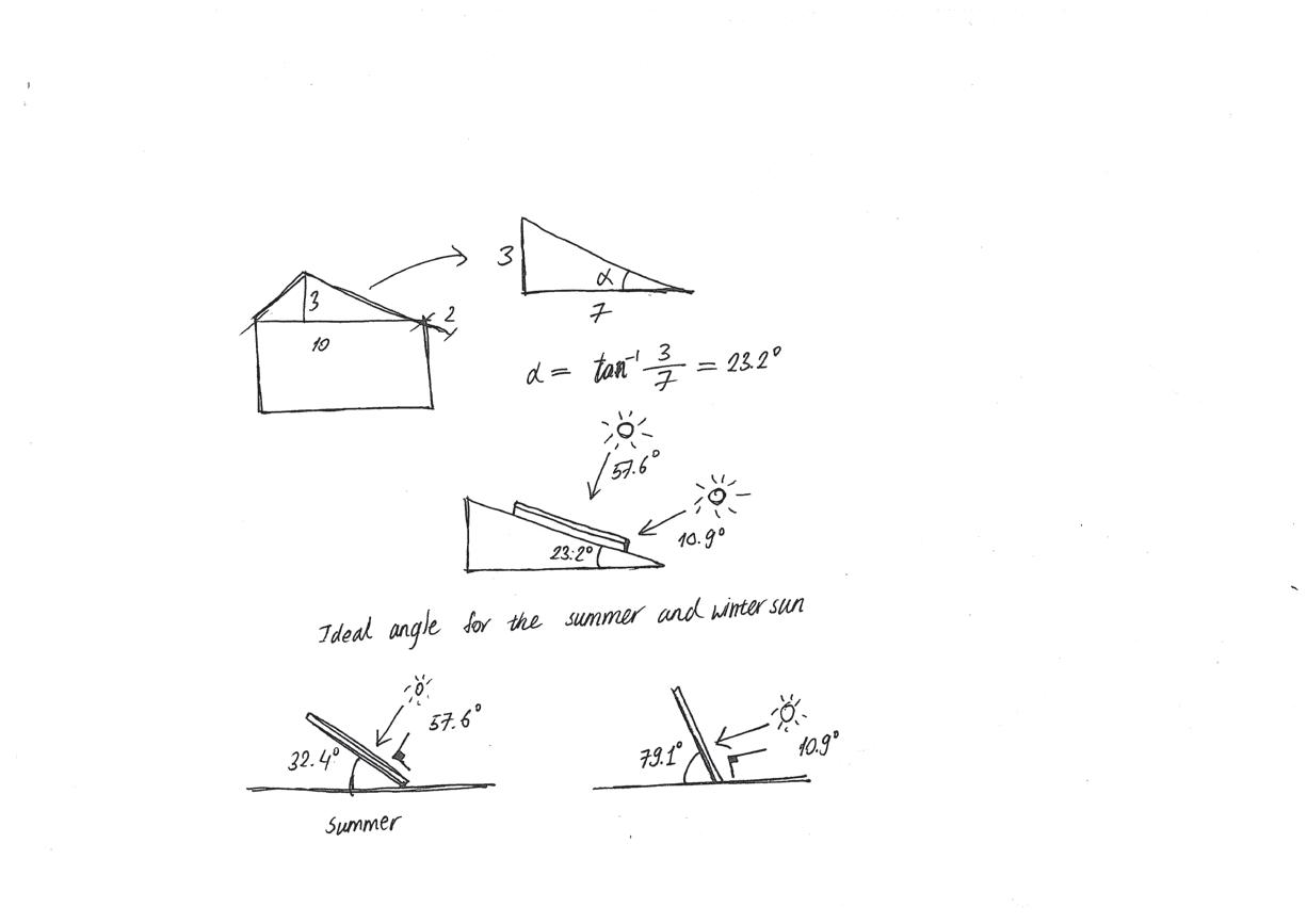
It is useful to show where your typical bay is taken from in the context of the rest of your building design, especially if it has developed signi
Different types of shading devices are employed. The roof overhang shades the building from high-angle summer sun but allows winter sun to enter for solar gain. There are bifold blinds on the West glazing and roller blinds for the rest.
Try to synthesise the many performances required of your building fabric and envelope design. Try to bring a coherent approach to the whole building concept into the design of your envelope, for example your approach to sustainability or cost that govern your massing and arrangement may also drive your approach to material selection and construction systems.
There needs to be further development made on the details of window fixing, envelope build-up, hidden gutters, and joineries in week 3.
Use small key drawings and diagrams where needed. You may also use these to capture environmental strategies that may have developed since Week 1.
During the night, the space is lit via low energy LED lights. They are seamlessly installed through the timber cladding for visual comfort. Solar panels generate electricity that is used for heating, artificial light, and other appliances. They change the angle of elevation seasonally to maximize the efficiency throughout the year. There should be space under the panels for the rainwater to run.
Floor layers
The building is partially heated via direct solar gain. When winter low-angle sun hits the floor, the heat is absorbed in the thermal mass and re-radiated to the space

Sectional isometric drawing Internal blinds


Adjustable solar panels for electricity
External bifold blinds
Cross ventilation in section and plan
Manchester School of Architecture BA Hons Architecture- Technologies Unit Handbook: BA2 Part C- Technologies Design Project.
Week 2
Typical
bay location
3.1 Integrative Detail Study - Iteration/ Ideation (1/2)
1) Detail Design Development
2) Sketch Development/ Ideation
Be creative and ambitious. Think back to the keynote lecture and the examples shown.
I dedicated 3.1 to detail iteration and development of the steel frame, raft foundation, floor, and South overhang.
Week 3 is an opportunity for you to demonstrate how you can join together all the aspects of architectural design to create an integrated concept that delivers successful interior environments, building on the work in Week 1 and 2.
Individual Communication (Output):
You may be interested in materiality and lighting effects or the technical challenges of shading systems. You may be interested in geometry that may apply to the solar performance or surface morphology and construction.
Iteration 1
You will evidence your detailed design development with two sheets showing design iterations/ development work followed by a ‘final’ iteration for your envelope, drawn up as a detail study. The final sheet will be a project synopsis and therefore is a graphical summary of the preceding work (not new/ additional work).
Study Methodology:
Building on the basic understanding of the steel frame structure of 1.3, I initially sketched the layout of the portal frames, purlins, and girts. An additional element that was considered for this week was bracing to resist lateral load and maximize structural strength. After a basic sketch, a more accurate layout of the steel frames was made with a SketchUp model.


Develop your envelope strategy from Week 2 using sketches, iterations, annotated screen grabs or photo’s of models etc, show how you are developing and resolving the detail assembly.
Iteration 2
Wall insulation was too thin for the first four iterations. There were cold bridging problems with the initial iterations. For the final foundation detail, insulation is added under the concrete slab to avoid cold bridging. Raft edge stiffener, flashing, steel column bolts and reinforcement are considered for the final version.


Iteration 3
Raft foundation development is done via loose detail sketch iterations. Along with the foundation, floor layers were also included. The insulation under the concrete in the final iteration is rigid insulation instead of sheep’s wool.
Use a combination of 3D isometric and 2D detail drawings to scale e.g. 1:5 or 1:10.
Do your thinking through drawing, on the page. This will very quickly advance your design and produce the evidence to include on these sheets. This should be a loose and dynamic set of drawings and diagrams but should be legible. Ensure you add annotation and captions so that it is clear what story you are telling of the evolution of the design - what steps are you taking in your the design decision making process.
A roof wall connection with the South overhang was also developed with detailed section sketches.


Glazing details and wall build-up should develop further on the next page.
You could use the framework of geometry, mass, light, air and water as a way to structure your thinking about the performance of your design.
You could also note down a summary of your process in a small number of bullet points so that the reader understands the significance of the drawings that you are showing.
After discussion with the tutors, I decided to replace the purlins and girts with Z ones. Tie bracing is between the columns and girts. Individual components are welded and bolted together as shown on the drawings. Steel columns are bolted via a base plate on the concrete foundation.


Iteration 1 had a continuous I beam for the roof overhang. After sketching it out, I realized that there is no need for insulation for the roof overhang as it’s not part of the building sealing component. Also, continuous I beam meant that there is more material wasted on a non-structural element.
Instead of a solid overhang, vertical louvers were considered as a shading device. Iteration 2 needed a gutter and a solution to conceal the steel portalisation to achieve a seamless interior finish. Although vertical louvers did the job of shading the South glazing from the Summer sun, they disrupted the clean and continuous exterior look.
Iteration 3 uses a cut down I beam extension for the roof overhang to save material and maintain the continuity of the exterior cladding. The roof overhang is not insulated and the cladding wraps the entire element. The timber ceiling is fixed further down to hide the portalisation whilst creating a void for services. The hidden gutter is located on the joint of the roof and wall.
19 November 2021 Manchester School of Architecture BA Hons Architecture- Technologies Unit Handbook: BA2 Part C- Technologies Design Project.
Week 3
Steel
Steel
Tie
Steel
Extension
Initial sketch
Pen isometric drawing of the frames
column footing
joinery Horizontal girt
bracing
portal frame Roof purlins
for overhang West face East face
Iteration 4 (West side)
Load
General arrangement of the steel frame
path
Iteration 5
Span of the purlins and girts
1:10 isometric view of the raft foundation (final version)
Iteration 1
Iteration 2
Iteration 3
3.2 Integrative Detail Study - Iteration/ Ideation (2/2)
1) Detail Design Development 2) Sketch Development/ Ideation

On page 3.2, I focused more on the wall build-up and glazing details through 3d views, sketches and detail drawings.

Initially, the positioning of the steel frame helped shape the wall build-up detail. Through the process of drawing the wall layers in 3d, plan, and section, a configuration of the build-up emerged. The aluminium rain-screen cladding is fixed to support vertical rails, which is connected to the z girts. As the interior finish conceals the steel structure, the insulation is fitted between the steel I columns and Z girts to minimize the wall thickness. In between the I columns, there is a sheep’s wool insulation, which provides the main thermal resistance. Wood fibre insulation is chosen due to its sustainability and rigidity to be installed in between the Z girts. On the 140mm vertical battens, 25mm horizontal battens are fixed to support the Scottish larch lining. The use of rain-screen, timber cladding, sheep’s wool, wood fibre insulation, and breather membranes construct a breathable wall with thermal, damp and vapour resistance.

For the second half of the sketchbook ideation process of 3.2, I focused more on the glazing details. There are 3 different types of glazing installed in the building: large West, long narrow, and small square awning windows. I’ve chosen steel frame windows for the availability in a wide range of sizes and the clean slim frame finish. All the windows are triple glazed with the U value of 1.3 W/m2K. Through the sketching process, the window interior, exterior look, opening, and frame details are considered and configured.


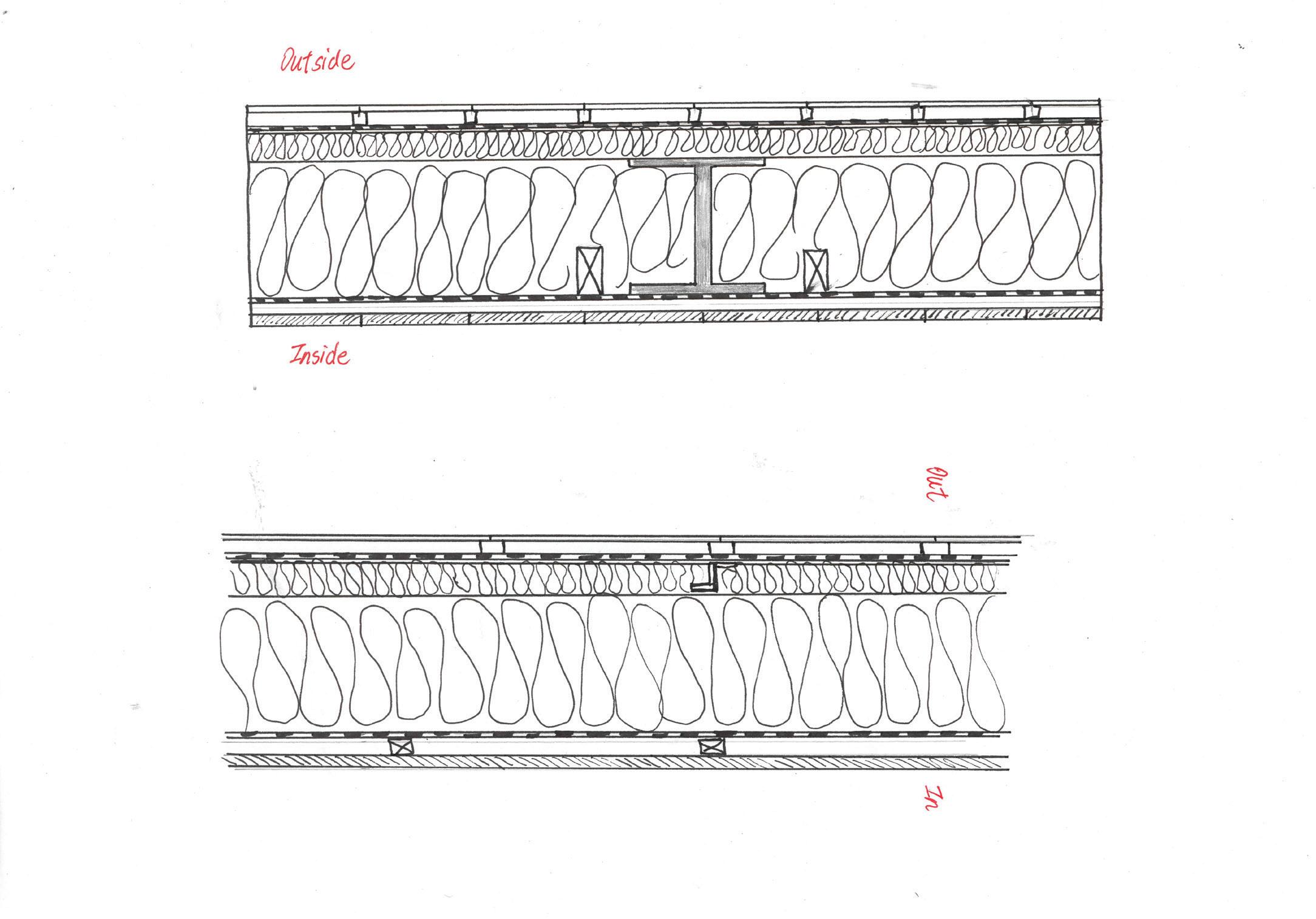


A. Typical continuous wall
B. Wall and West glazing connection
C. Wall details of the corner
Manchester School of Architecture BA Hons Architecture- Technologies Unit Handbook: BA2 Part C- Technologies Design Project.
Week 3
Initial sketch of the purlins’ location and wall build-up
Wall build-up detail 3d sketch
Wall build-up detail sketches in plan
1:10 final detail of the wall build-up in section
1:10 final detail of the wall build-up in plan
Initial sketches of the glazings
Interior view of the small glazing Exterior view of the small glazing
Detail sketches of the small glazing Steel frame details
Large glazing detail sketches
3.3 Integrative Detail Study - Synthesis & Argument


1) Summary
Use this sheet to describe in detail and specifically how the building envelope design you have


The multi-use community hall building in a rural area of Glasgow Scotland, employs several passive and active environmental strategies, such as solar gain via South facing glazing, cross ventilation, energy generation via solar panels, low energy appliances, and rainwater harvesting. The primary structure consists of prefabricated steel portal frames, girts, and purlins on a reinforced raft foundation, which distributes the building load down to the loose alluvial soil evenly. The building is highly insulated with sustainable sheep’s wool and wood fibre to reduce energy demand and reach Passivhaus standards. Furthermore, the glazing is strategically positioned to maximize solar gain and minimize heat loss. Finally, the interior finish is completed with ethically sourced Scottish larch cladding and flooring.

2) Detailed Envelope Design - Annotated 3D Drawing/ Model
Include in your annotations considerations for
3) Annotated Thumbnail Drawings
5mm Aluminium rain screen
facade
Breather membrane
11mm OSB
80mm Wood fibre insulation
300mm Sheep’s wool insulation
11mm OSB
Air barrier
25mm batten

20mm Scottish larch lining
5mm Aluminium rainscreen
facade
Breather membrane
11mm OSB
80mm Wood fibre insulation
300mm Sheep’s wool insulation
11mm OSB
Air barrier

200mm void
20mm Scottish larch lining
30mm Scottish larch flooring
50mm Concrete floor screed+Underfloor heating
100mm Sheep’s wool insulation
Damp proof membrane
300mm Reinforced concrete slab
100mm Rigid insulation
BA Hons Architecture- Technologies Unit Handbook: BA2 Part C- Technologies Design Project.
Week 3
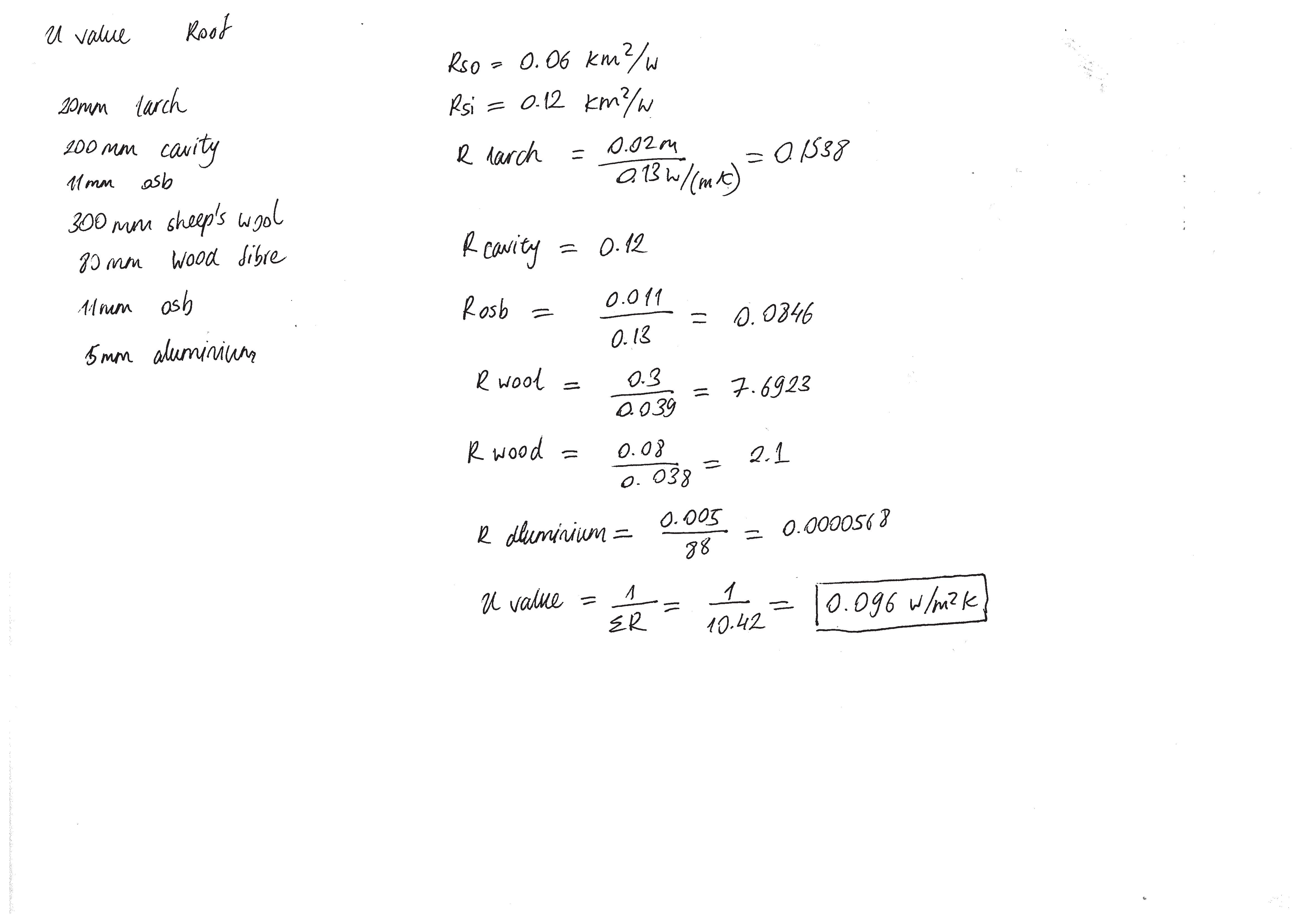
Exploded isometric view Wall detail Roof detail Wall U value calculation Roof U value calculation Floor U value calculation Floor detail
Perspective drawing at A2
3.4 Integrative Project Synopsis - Synthesis & Argument
Use this sheet to show your best images as a synopsis of the project and the process you went through as well as communicate your design. If you wish, you may make improvements and make adjustments based on previous feedback from each week of the


A single sheet graphical summary to show images and drawings from each week of the project. This sheet should be graphical.


Consider this as a sheet that you may show at an interview to show, at a glance, the range of techniques you have used along side drawings that explain your design overall design. It could also be considered similar to a competition entry - think back to your final sheets for Papermetrics where you summarised your designs.
Avoid over-filling the sheet and cramming too many small images


You do not need to include text on this sheet apart from image titles and very short captions (detailed narrative exists on your earlier

19 November 2021 Manchester School of Architecture BA Hons Architecture- Technologies Unit Handbook: BA2 Part C- Technologies Design Project. Week 3
of synoptic presentations will be reviewed in the lecture Site strategy diagram Climate strategy diagram 1:200 section 1:200 Ground floor plan
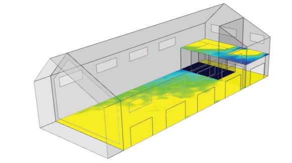
Sefaira
Environmental strategies diagram Typical bay section drawing Elevations Interior and exterior view Steel frame layout Foundation detail Wall build up sketch Roof detail Floor detail Exploded isometric view Perspective view Improved floor plans Steel frame layout Wall build-up North elevation East elevation Exterior perspective Interior perspective
Examples
Sefaira analysis for glazing
amount
analysis for glazing distribution