
>> Digital exploration of Protein deformation
Explain bio-type >> 3
Conditions of deformation >> 4
Recap Physical model >> 5
Principle >> 6
Correlate principle to enviromental conditions and site conditions >> 7
Reflect limitation >> 8
Path of digitalization >> 9
Initial digitalization >> 10
Site analysis >> 11
Translate site for computaion >> 12
Assumptions >> 13
Series A >> 14
Series B >> 15
Series C >> 16
Synchronize Forms to Site >> 17
Series H >> 18
Conclusion and render >> 19
Possible direction >> 20
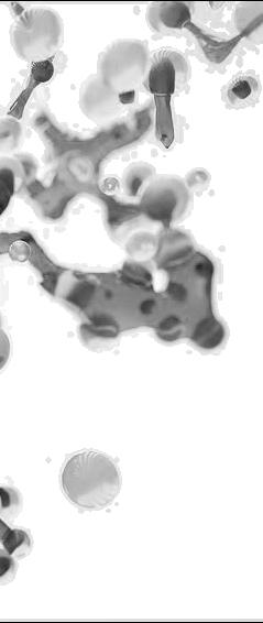
Peptides (protein fragments)
Explain Bio-type
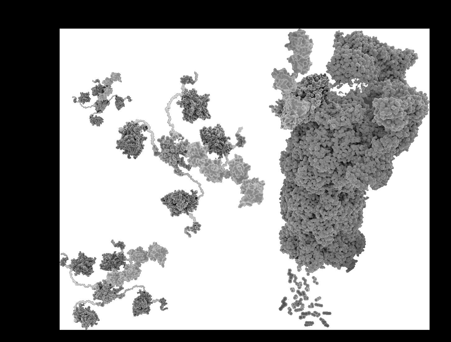
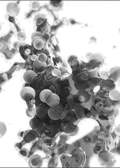
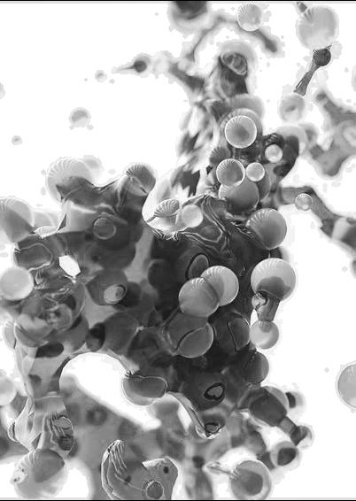
Proteolysis
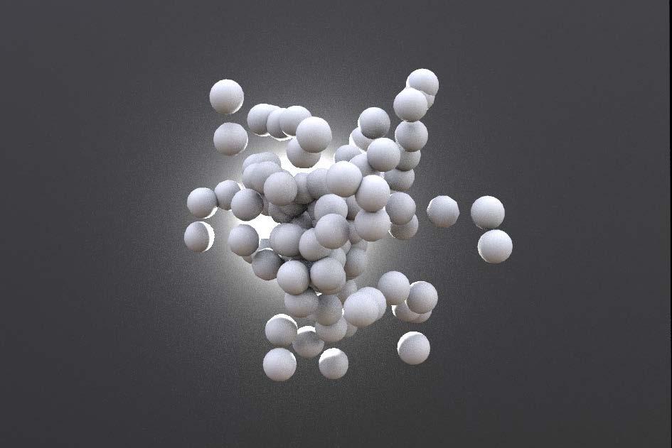
>> Protein deforms to amino acids when certain conditions are achieved
Apply changing conditions
Deform


>> Force and density

>> Delution


>> Heat absorption

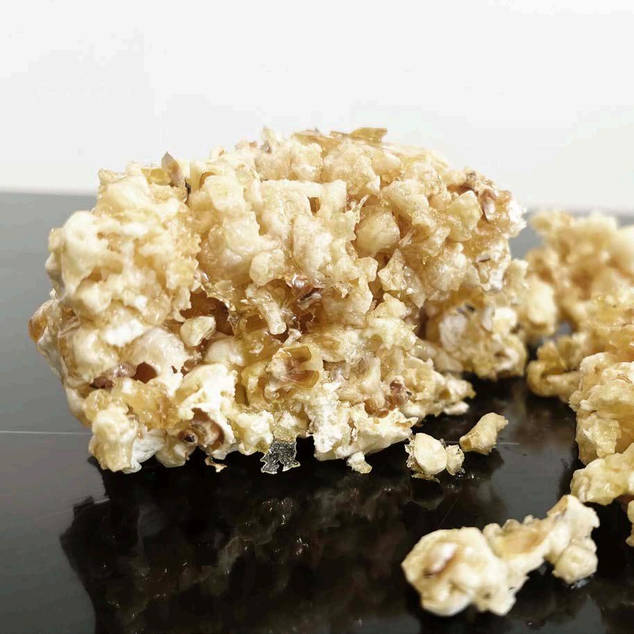
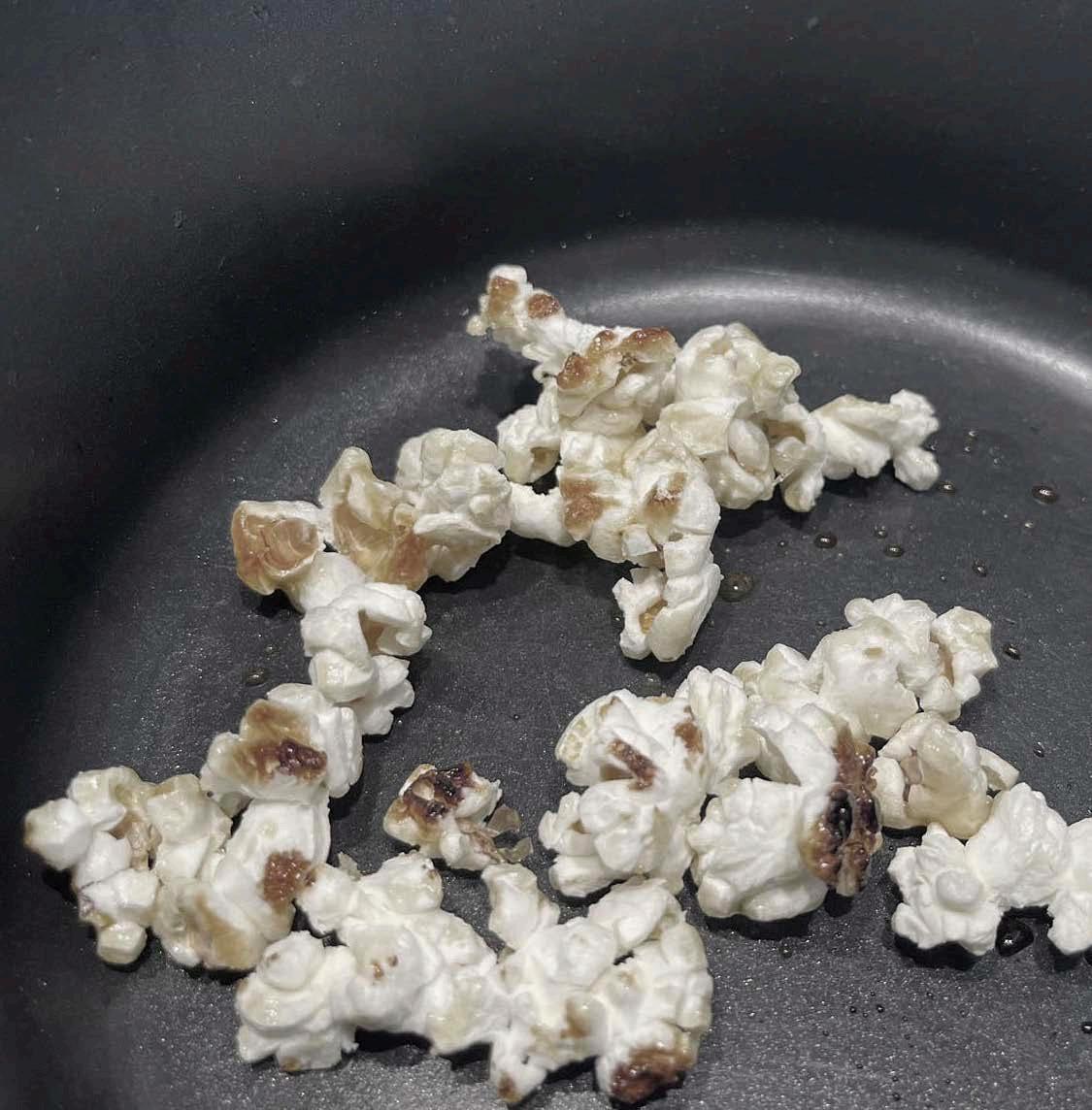

>> The model simulated and experimented the changing process of protein. It imitated the deformation in 3 conditions:
>> Adding force and density to popcorns inside a container. changing amount of popcorns or sugar gave different shapes and strength to the cluster.
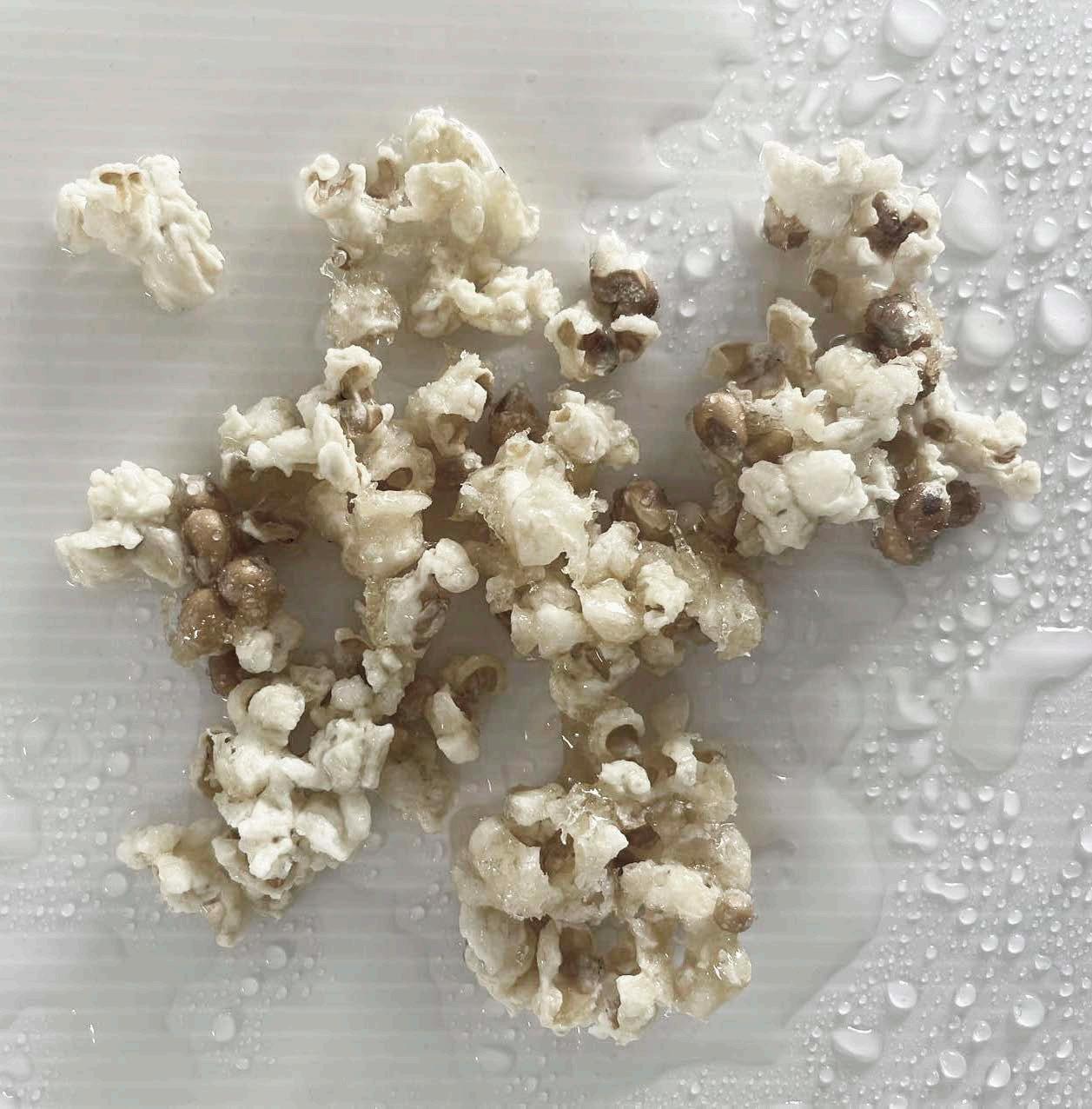
>> Adding water to a popcorn cluster, the deformation process followed the volume of water applied.
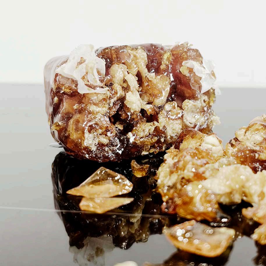
>>Adding heat to a popcorn cluster, the deformation process followed the rises of temperature.
Bio-type
Interpretion of principle
Conditions
Process
>>Force and density
>>Delution
>>Heat
Protein
>>Current or gravity
>>Humidity or landform
>>cliamate or vegetation
Scattered popcorns
Deformation
principle to enviromental conditions and site conditions
Protein
Bio-type conditions
Force and density
>> current >> gravity >> pressure General Enviromental conditions
Delution
Heat
>> humidity >> rainfall >> PH value
>> global latitude >> cliamate zone >> vegetation >> landform
>> terrain Specific Conditions at chosen site
>> Wind pattern
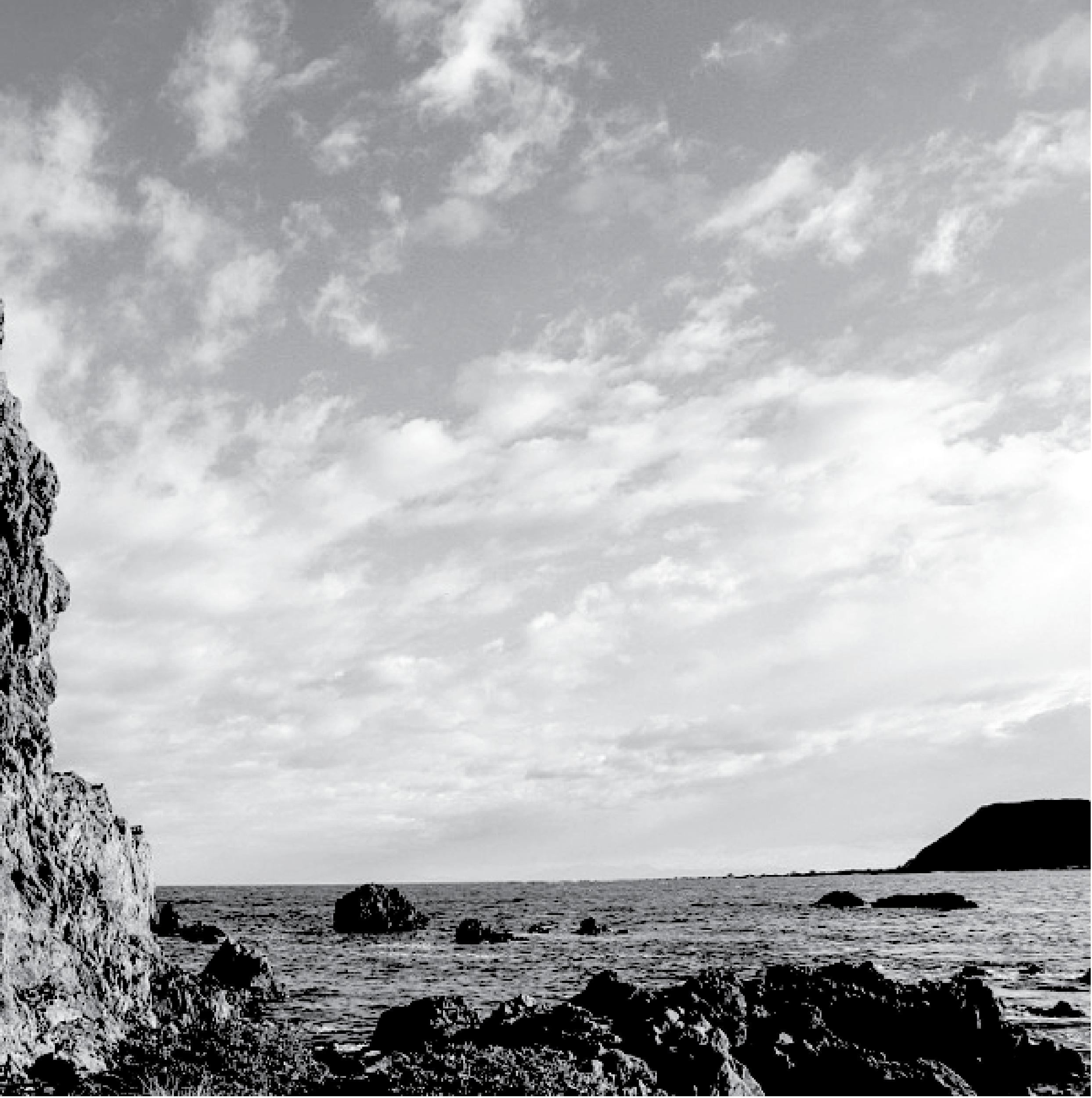
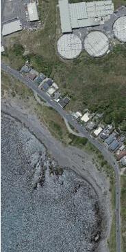
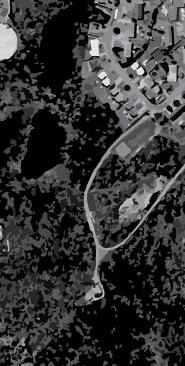
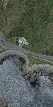
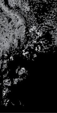
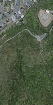
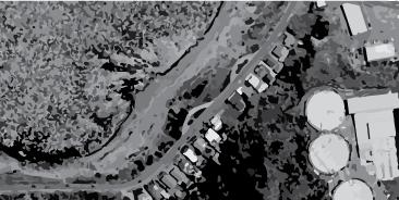
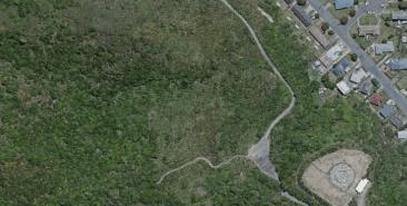
>> Moa point was chosen as the specific site to investigate and build model on.
Moa point is a coastal area close to Wellington airport, It includes gentle terrain changes, coastal landform and human factors as well
>> Volume of seawater >> sea level
>> Distribution of plants
>> Heat absorption by various landform
>> It includes natural conditions we need to generate protein deformation.
>> We will further divide site to smaller blocks to specify differentiated enviromental information.
Project ONE Limitation:
>> The micro condition of the bio-type is hard to simulate in a limited range of marerials and the natrual transformation generally lasts a long time span and hard to observe.
>> Therefore the chosen approach of the process was simplified and manipulable, it can not represent the natural deformation of protein completely and accurately.
Project TWO Methodology:
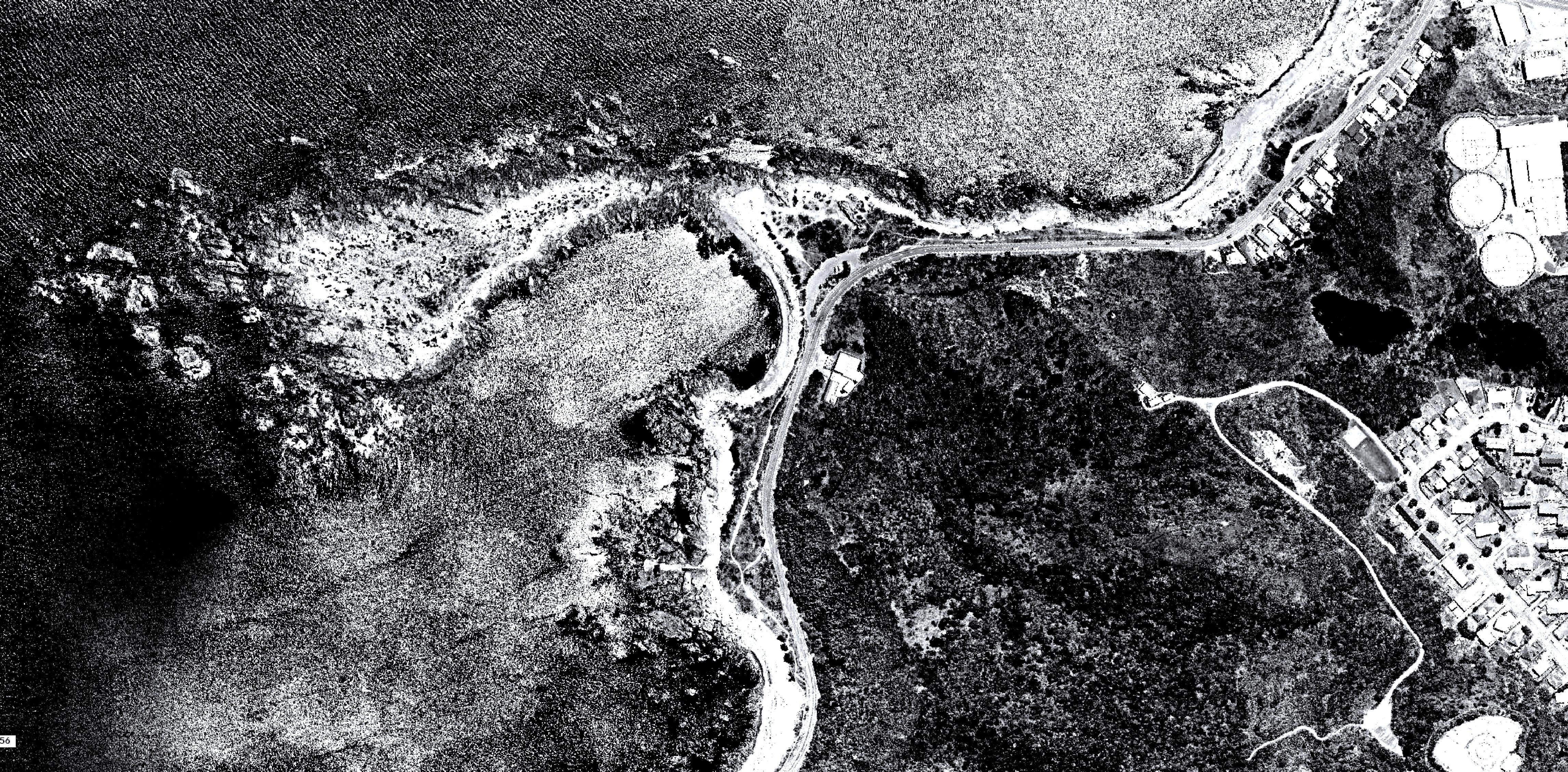
>> Site will be divided to blocks for analysing.
>> Only considers some of the most significant environmental conditions of the site. The site analysis will focus on these chosen conditions.
>> In order to explore the computational method of generating forms, site conditions will be consider and digitalized one by one. After achieving a clue of how the form react to each site condition, we will attempt to introduce multiple changed and generate hybrid interpretation.
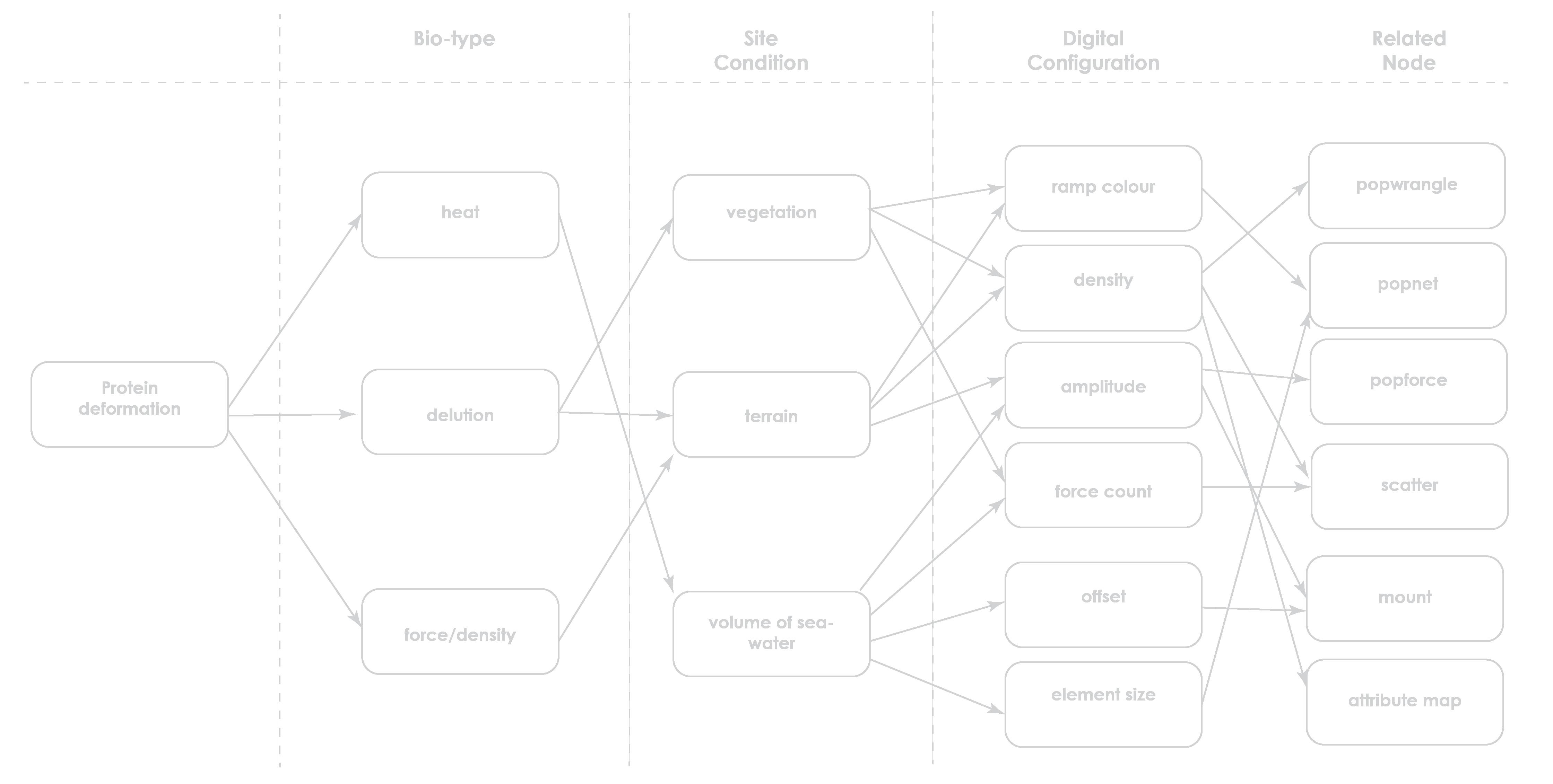
>> will possiblly be particle related nodes
Sphere1 radius: 2
Sphere2 radius: 0.2
Search radius: 2.78
Max search points: 3
Wire radias: 0.05
Round corners
Remove polygon
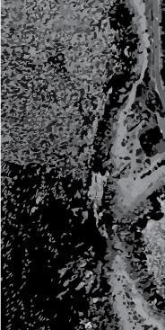
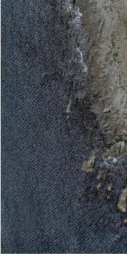
Row C includes large volume of seawater, some reefs and rocks, small area of land. The behavior and volume of sea water is the main feature.

>> Change of enviromental conditions will shape the deformation of protein. The site is devided in there rows. Each row has different environmental habitat.
>> The site is divided to 3 rows, each row stands for its own environmental features,
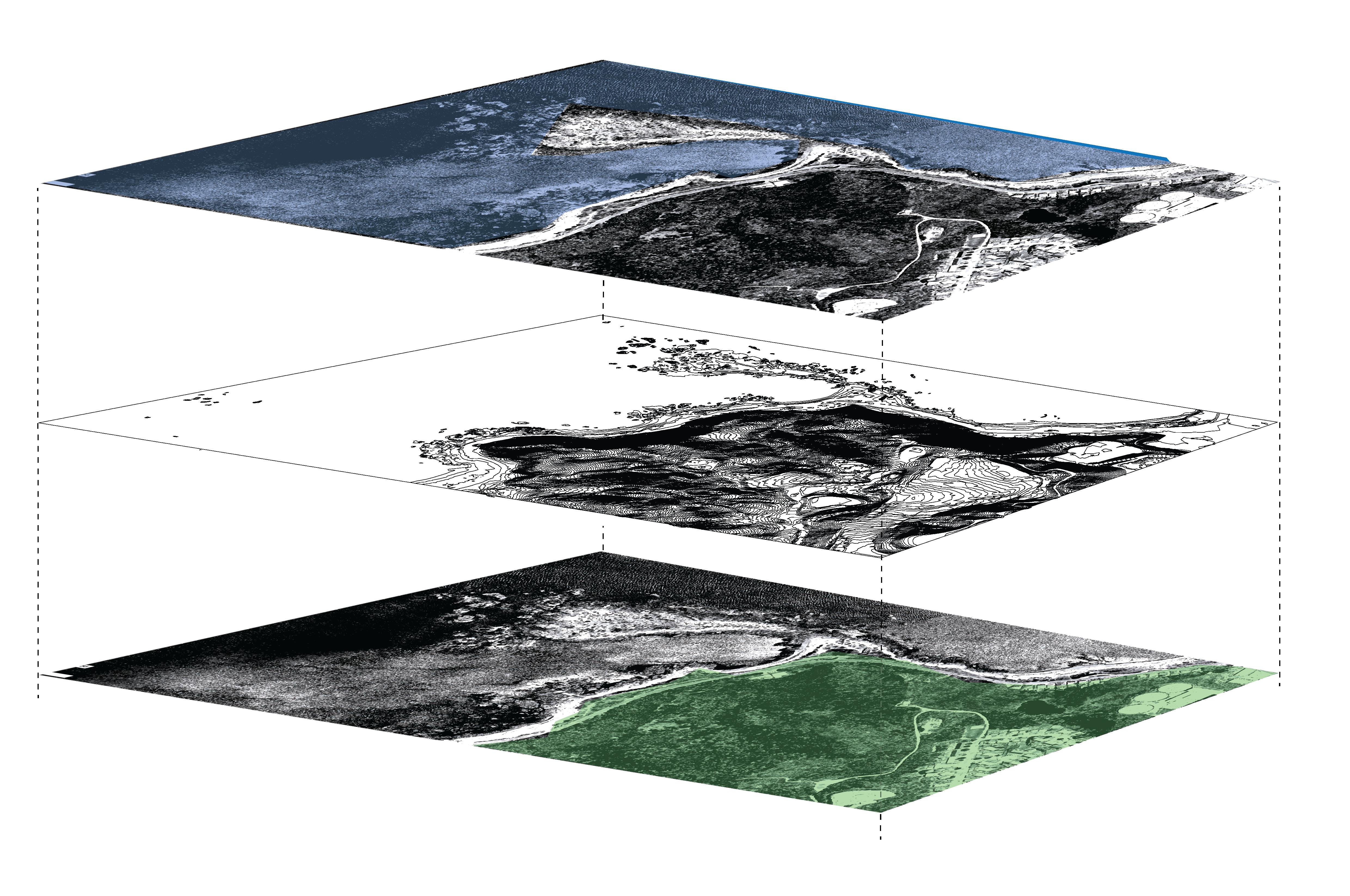
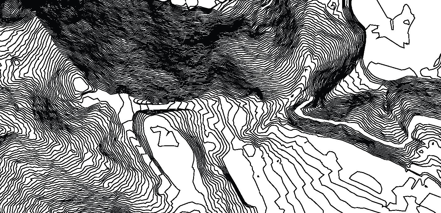
The main feature in B is the change of terrain. Land rises up from below sea level to hillside and then flattens out at the high level.
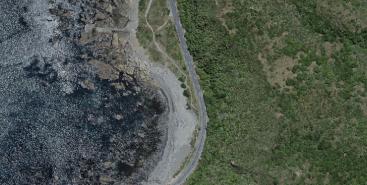
The uneven distribution of kelp and coastal vegetation characterizes row A
Quantify conditions for computation
Toggle bar indication

Translate site to script flow
>> 3 rows are subdivided to 9 blocks.
>> Each block configures quantified environmental condition individually, as script logics of the computation.
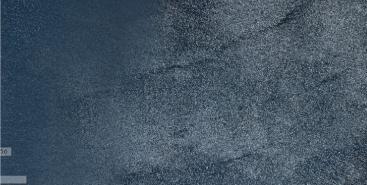
Volume of Seawater
Change of terrain
>> mounting geometry to indicate winding coastal line
>> ramp colours to interpret heat absorption
>> scatter points to surface
>> popnet project to surface
Vegetation
>> grid
>> attribute from map
>> contour map
>> scatter points by density
>> popnet along curve
>> grid
>> attribute colour “cd” from photo
>> scatter density from colour
>> pointwrangle to set start points for grow
>> popnet from starting points on grid
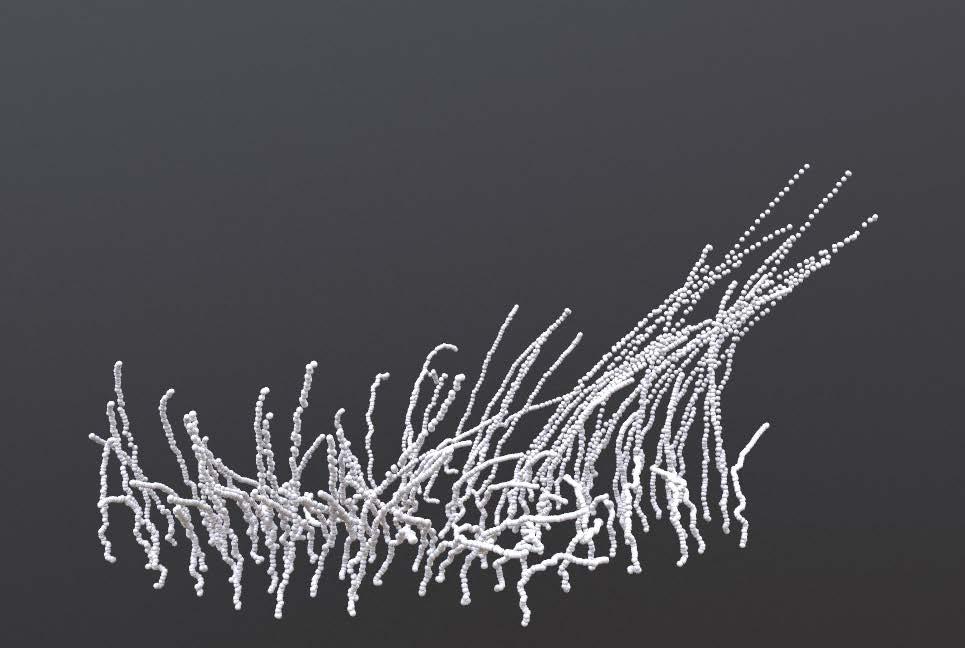
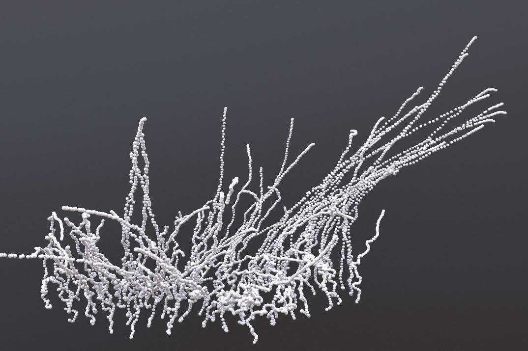
A vegetation
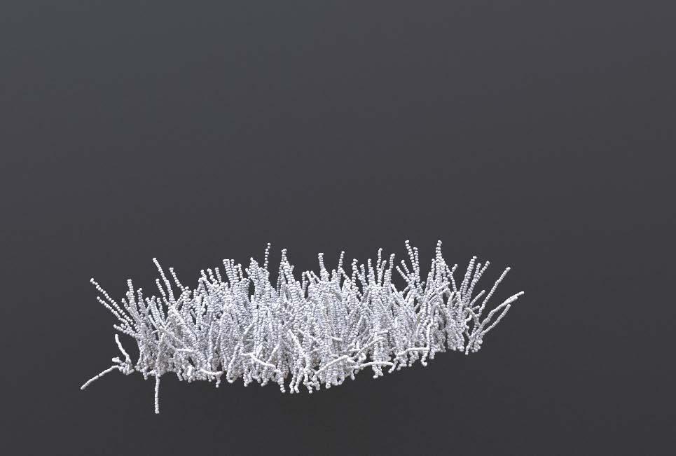
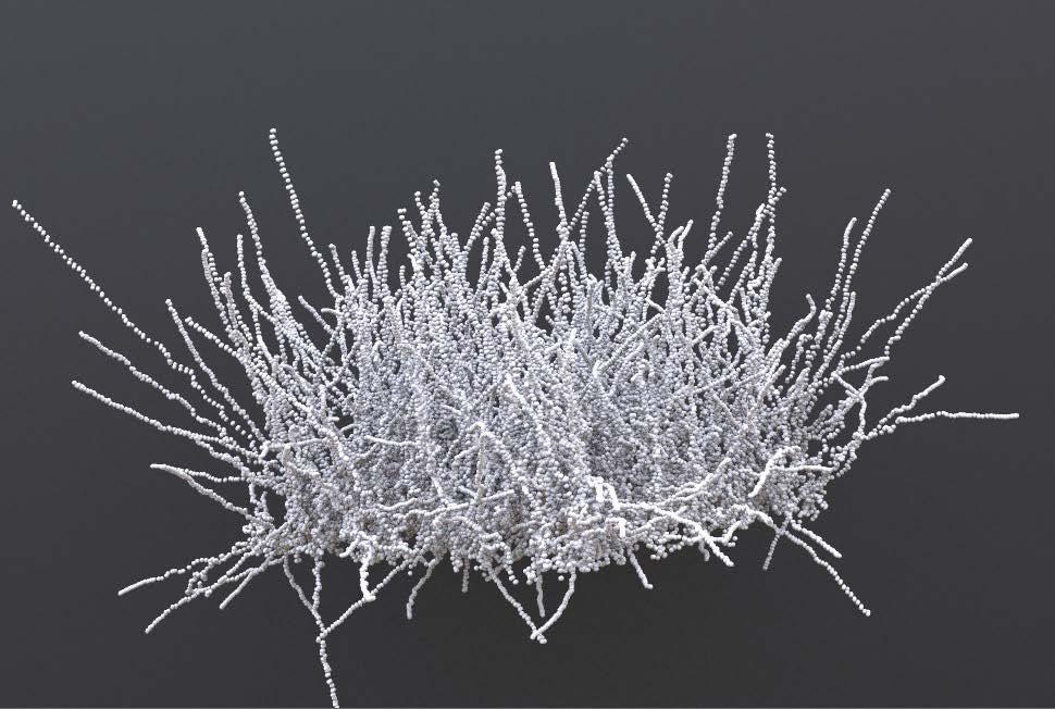
>> Protein particles will follow the growthing pattern with plants
Underwater Coastal Hills
A1. grow all direction
B Terrain
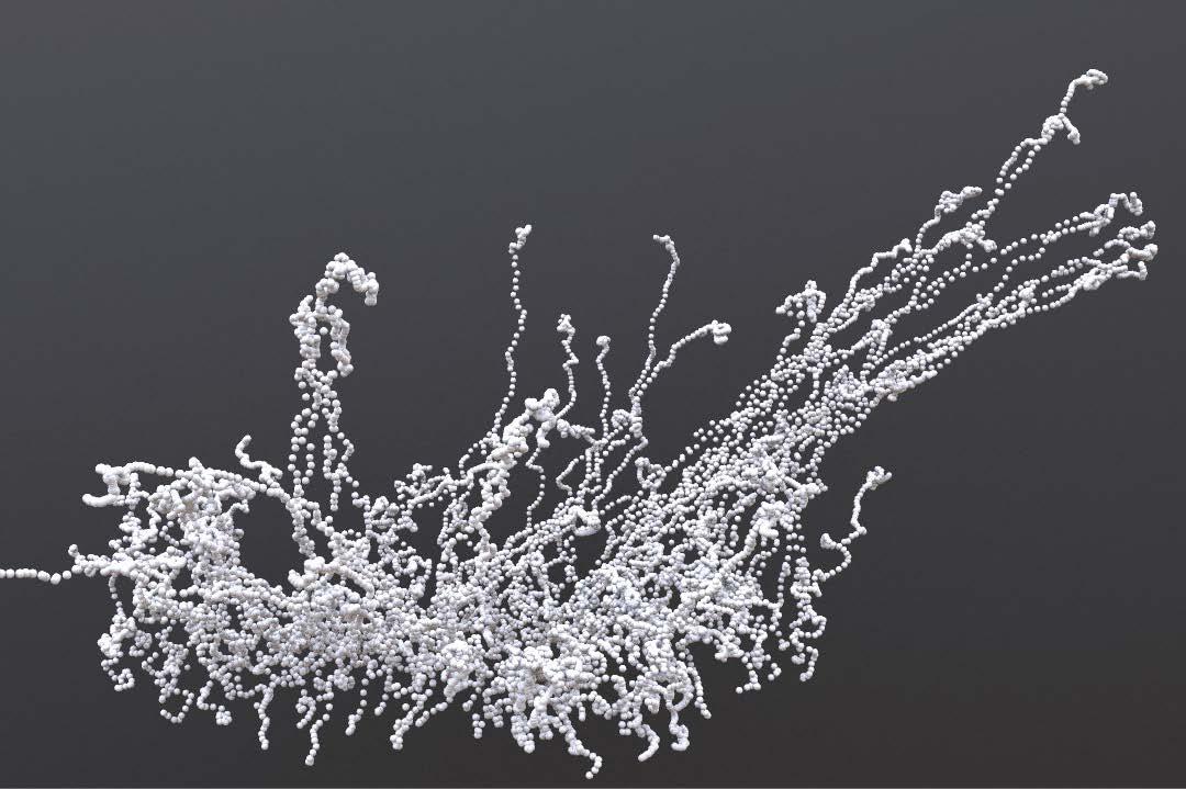
>> Protein particles will follow the pattern of air flow current
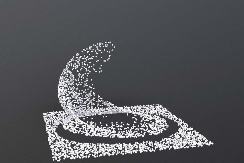
C Water
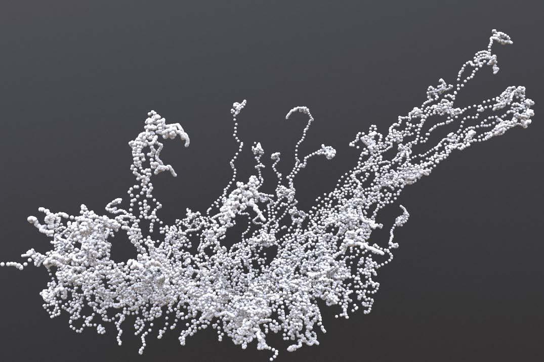
>> Force from water will round corners, protein particles will row in streamline
>> Force total count: 250
>> Amplitude: 10
>> Swirl size: 5
>> Swirl scale: 20,5,1
>> Impulse: 2
>> Impulse count: 2
>> Force total count: 100
>> Amplitude: 1
>> Swirl size: 10
>> Swirl scale: 1,1,1
>> Impulse: 1
>> Impulse count: 1
>> Force total count: 500
>> Amplitude: 2
>> Swirl size: 1
>> Swirl scale: 1,1,1
>> Impulse: 2
>> Impulse count: 2
Manipulate parameters
>> Force total count: 5000
>> Max influence radius: 3.5
>> Follow scale: 10
>> Suction scale: 1
>> Inherit velocity scale: 1
>> Particle size: 0.1
>> Follow force falloff from curve:
>> Force total count: 10,000
>> Max influence radius: 10
>> Follow scale: 2
>> Suction scale: 5
>> Inherit velocity scale: 4
>> Particle size: 0.3
>> Follow force falloff from curve:
>> Force total count: 1000
>> Max influence radius: 2
>> Follow scale: 1
>> Suction scale: 1
>> Inherit velocity scale: 5
>> Particle size: 0.1
>> Follow force falloff from curve:
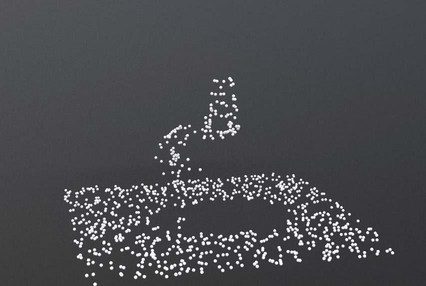
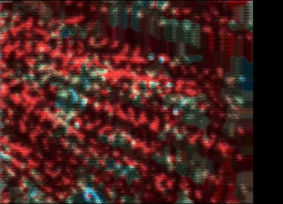
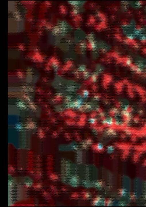
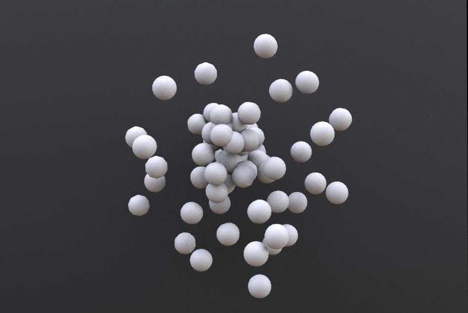
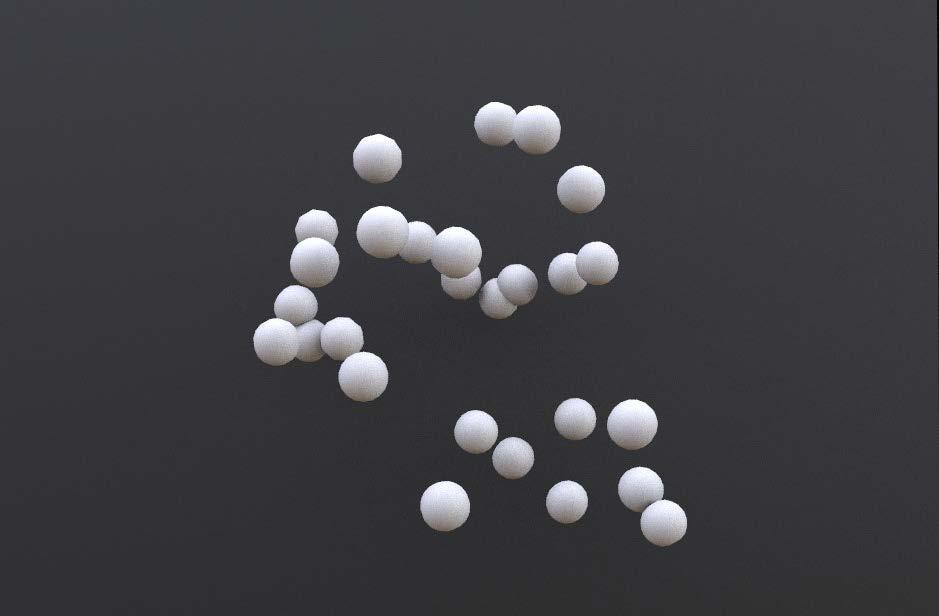
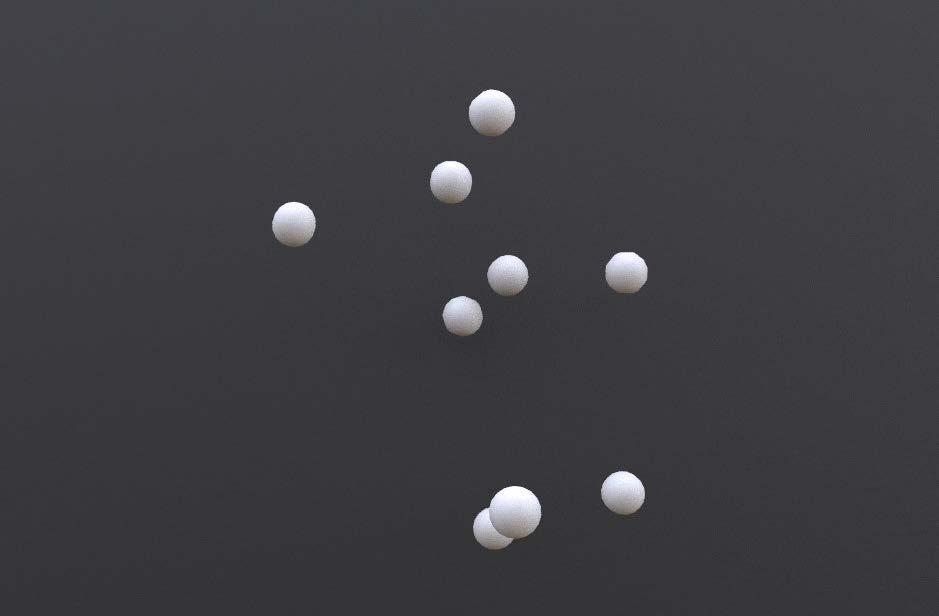
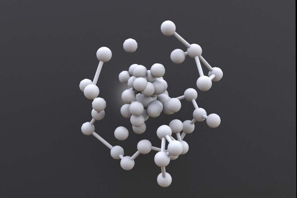
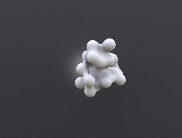
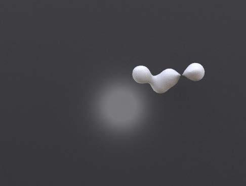
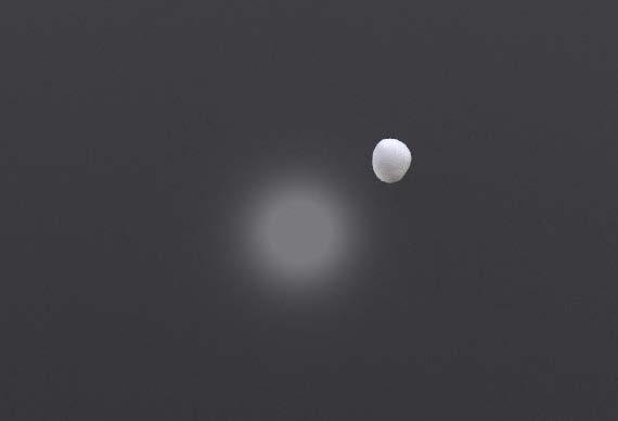
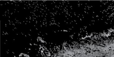
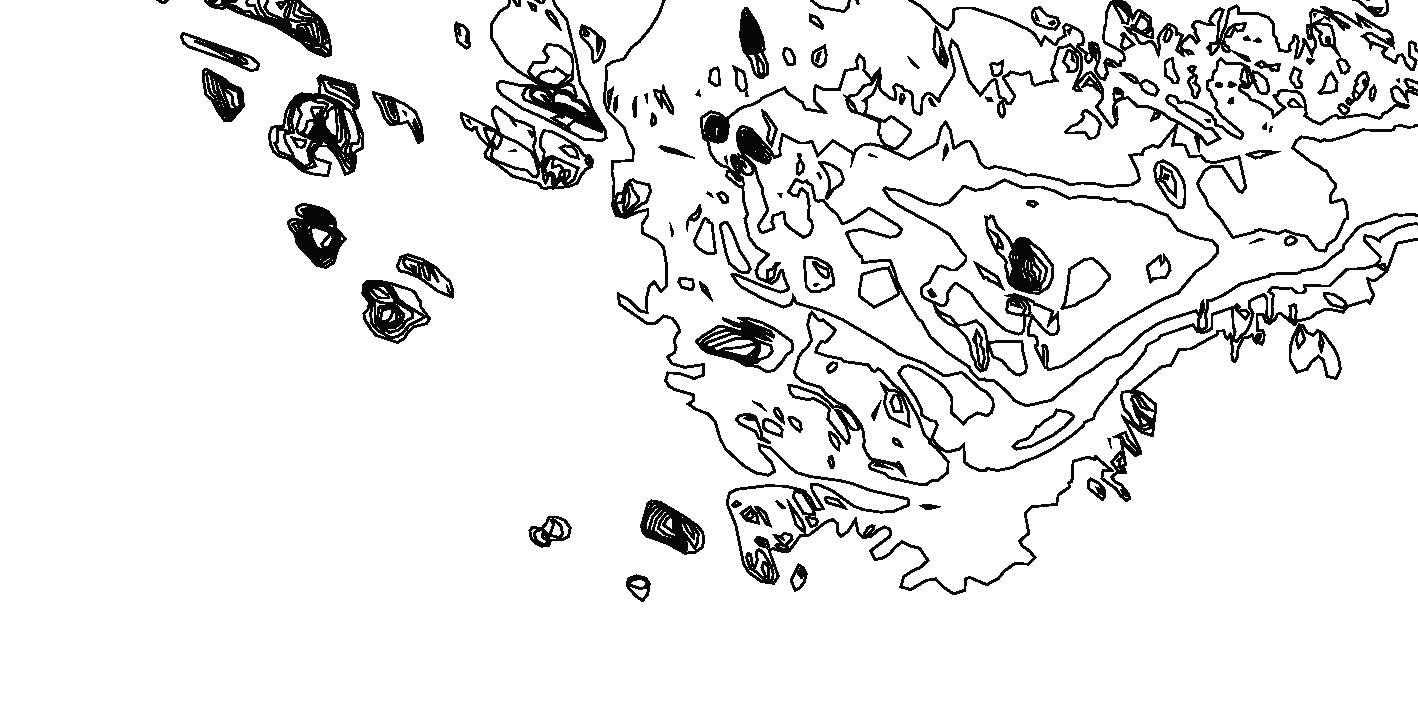
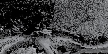
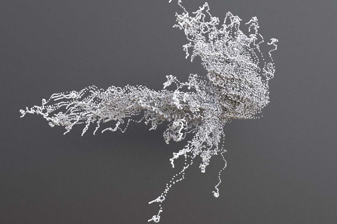
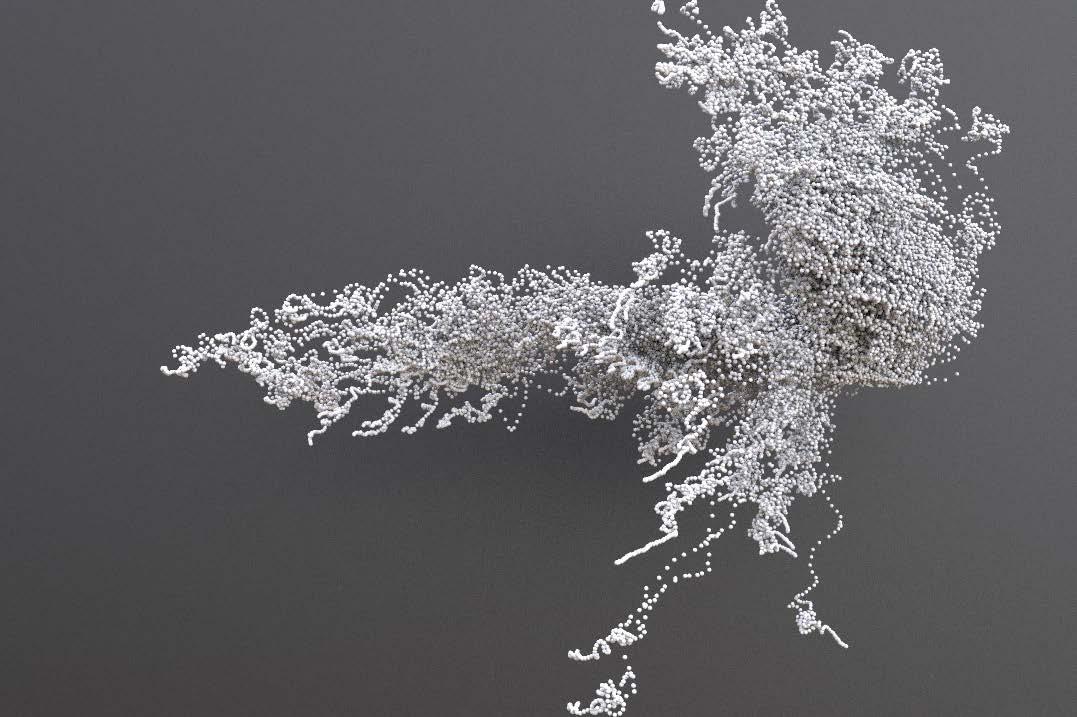
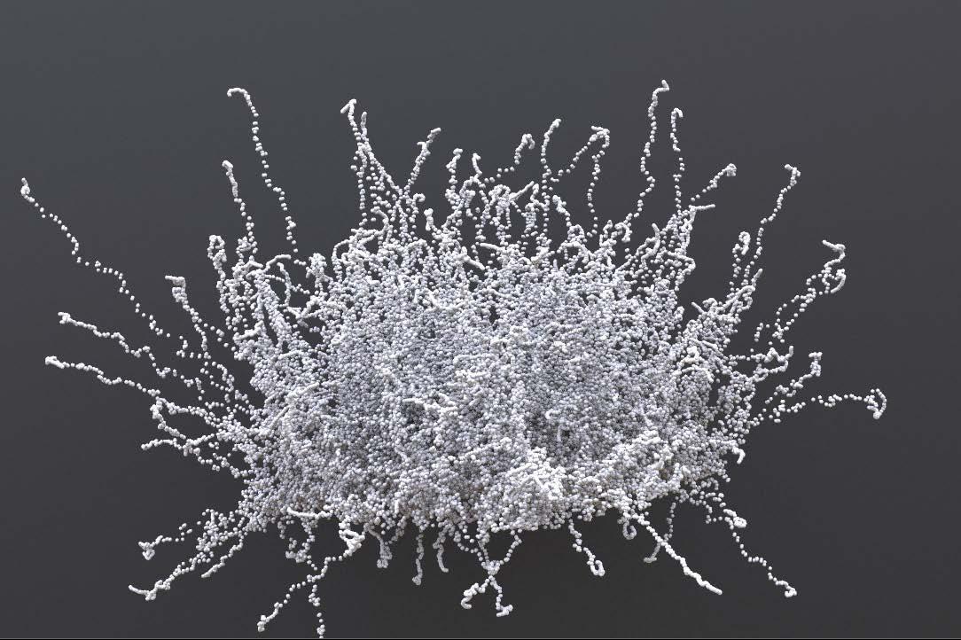
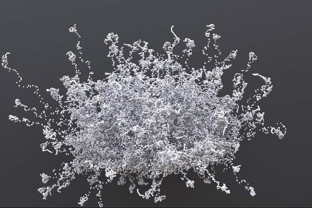
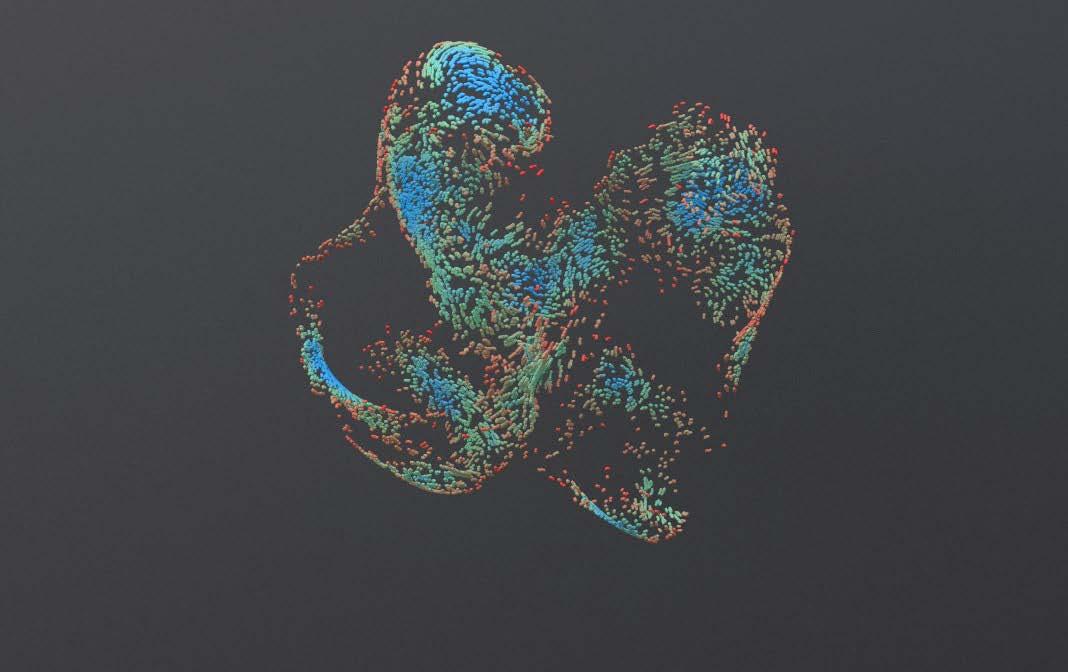
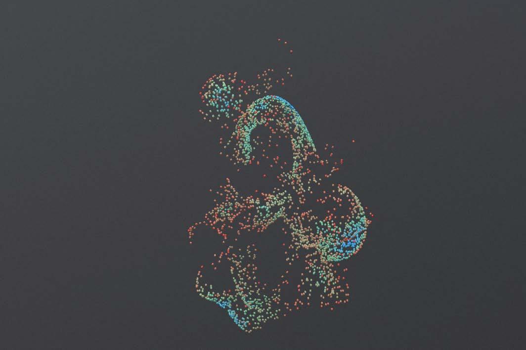
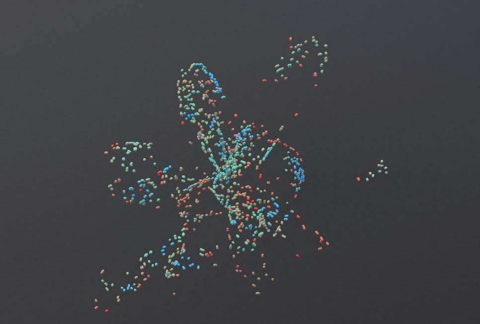
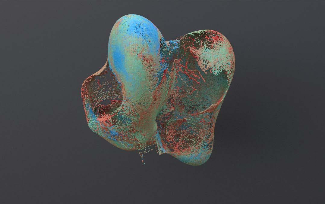
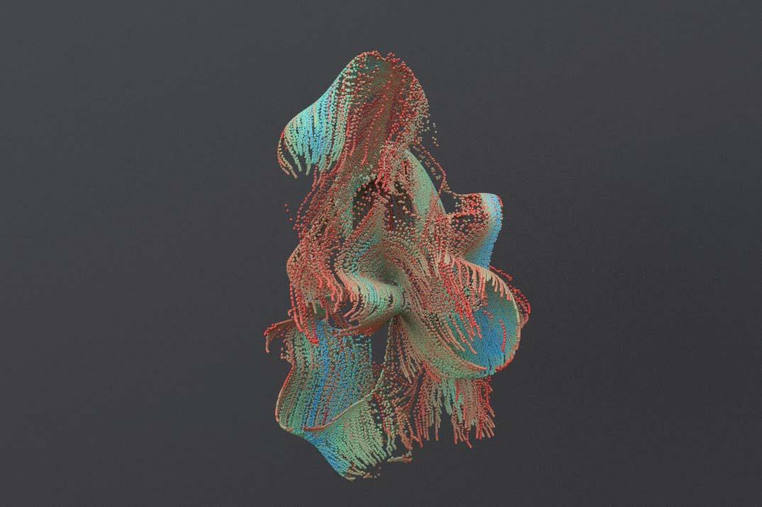
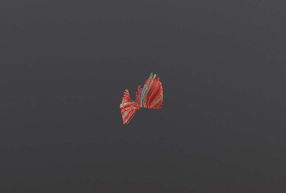
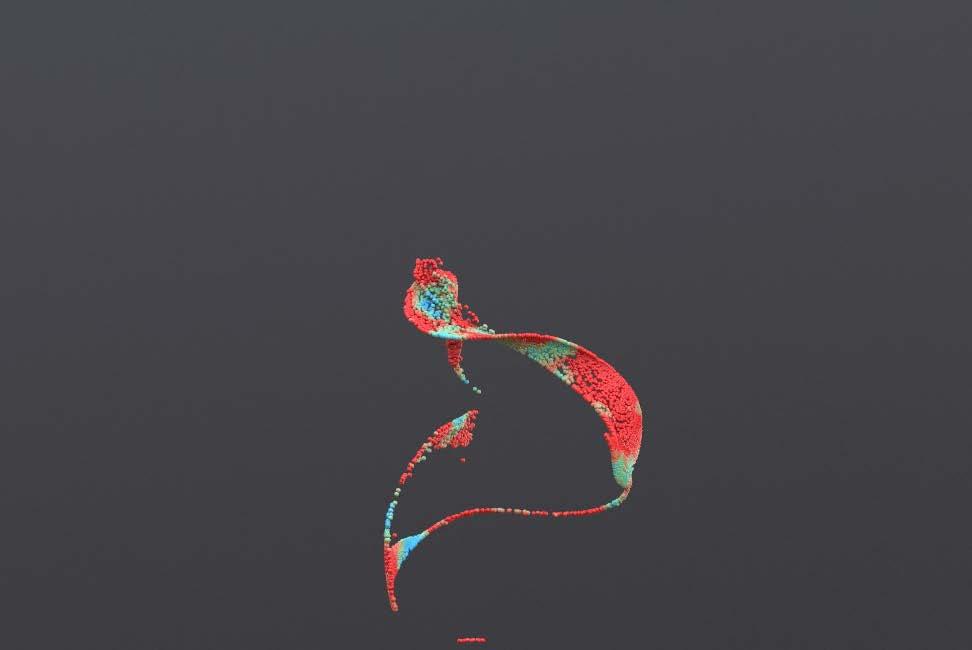
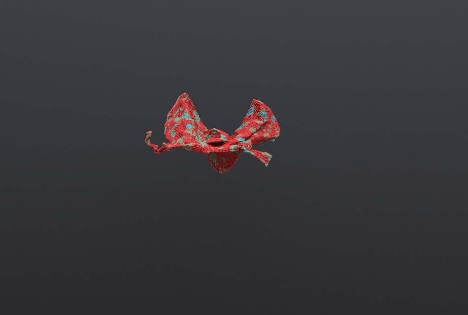
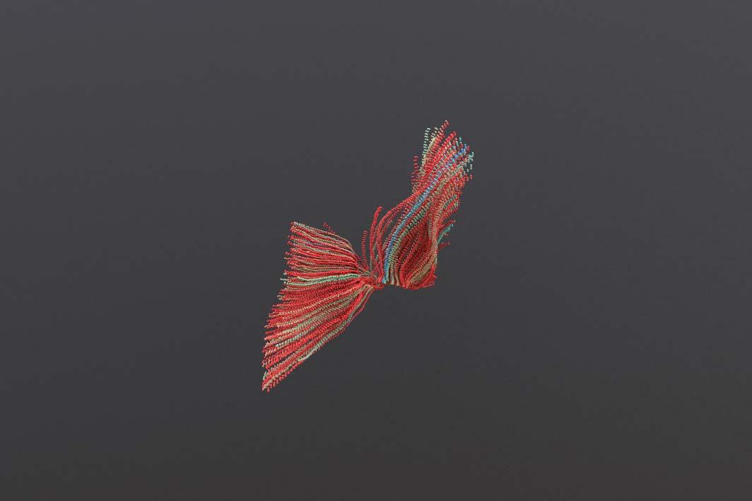
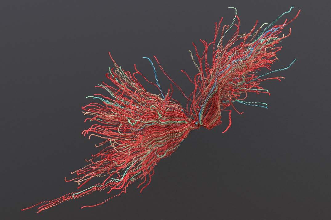
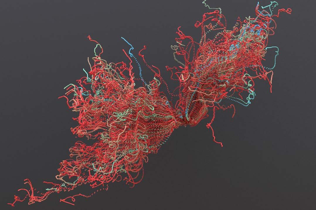
Protein deformation
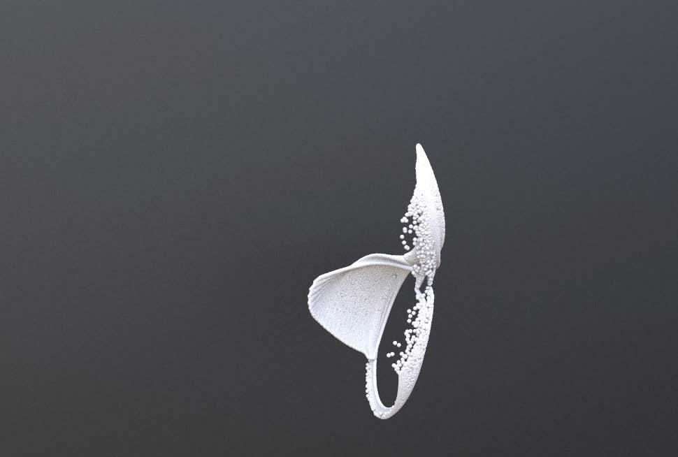


>> Force total count: 5000
>> Amplitude: 2.24
>> Element size: 1.19
>> Offset: 4.23
>> Max octaves: 0.32
>> Lacamarity: 1.721
>> Roughness: 0.527
>> Particle size: 0.02
>> Ramp colour:
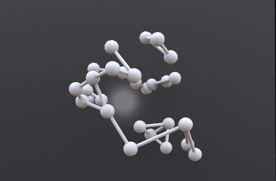
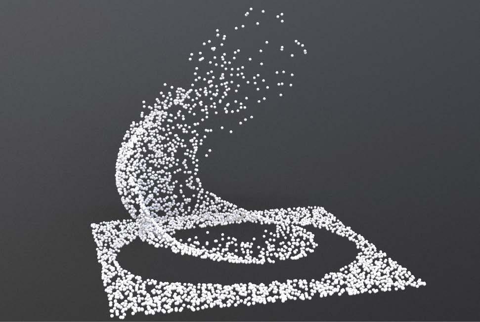
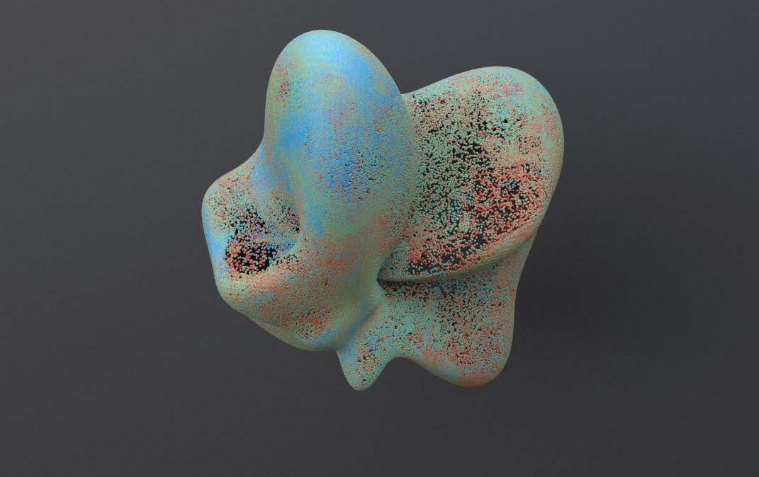
>> Force total count: 3000
>> Amplitude: 1
>> Element size: 0.7
>> Offset: 3
>> Max octaves: 6
>> Lacamarity: 0
>> Roughness: 0
>> Particle size: 0.01
>> Ramp colour:
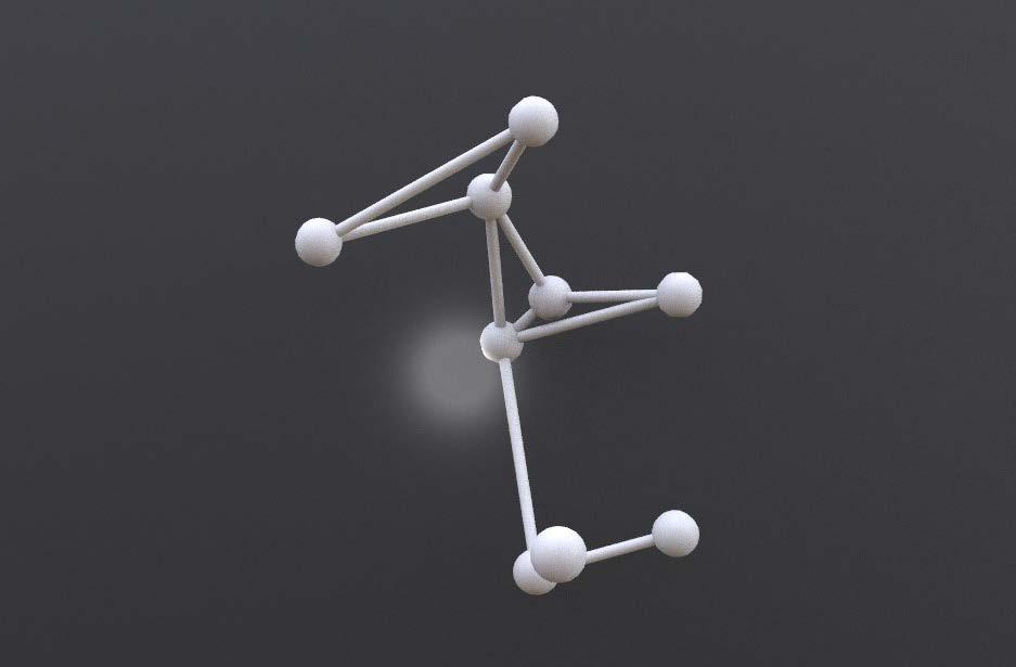
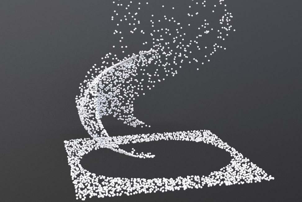
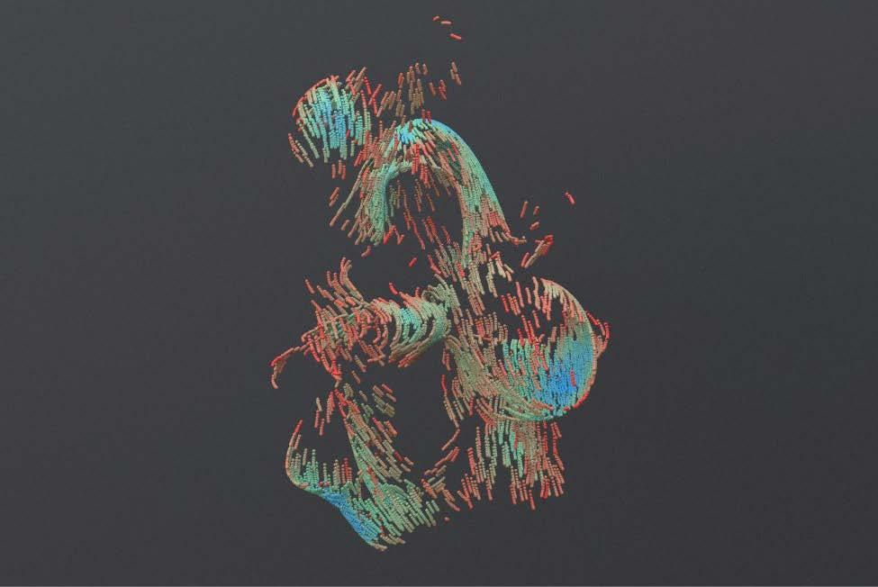
>> Force total count: 1000
>> Amplitude: 4
>> Element size: 0.8
>> Offset: 3
>> Max octaves: 0.6
>> Lacamarity: 2
>> Roughness: 0.2
>> Particle size: 0.04
>> Ramp colour:
>> Inpulse activation: $F<2
>> Air resistance: 1
>> Max Influence radius: 6
>> Follow scale: 2
>> Suction scale: 10
>> Obit scale: 10
>> Velocity scale: 5
>> Follow force scale:
>> Force count: 1000
>> Particle size: 0.1
>> Ramp colour:
>> Amplitude: 10
>> Swirl size: 5
>> Swirl scale: 20,5,,1
>> Pulse length: 1
>> Roughness: 1
>> Atthenuation: 1
>> Tubulence: 1
>> Offset: 0,0,0
>> Force count: 500
>> Particle size: 0.2
>> Ramp colour:
>> Popforce: 1,-1,0
>> Amplitude: 10
>> Swirl size: 5
>> Pulse length: 1
>> Roughness: 1
>> Atthenuation: 1
>> Tubulence: 1
>> Offset: 0,0,0
>> Force count: 1000
>> Particle size: 0.2
>> Follow force scale:
>> Ramp colour:
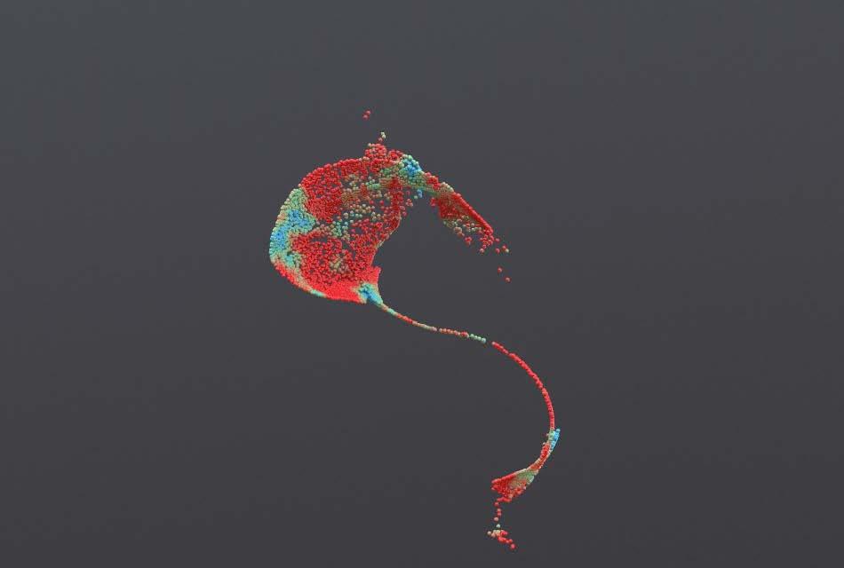
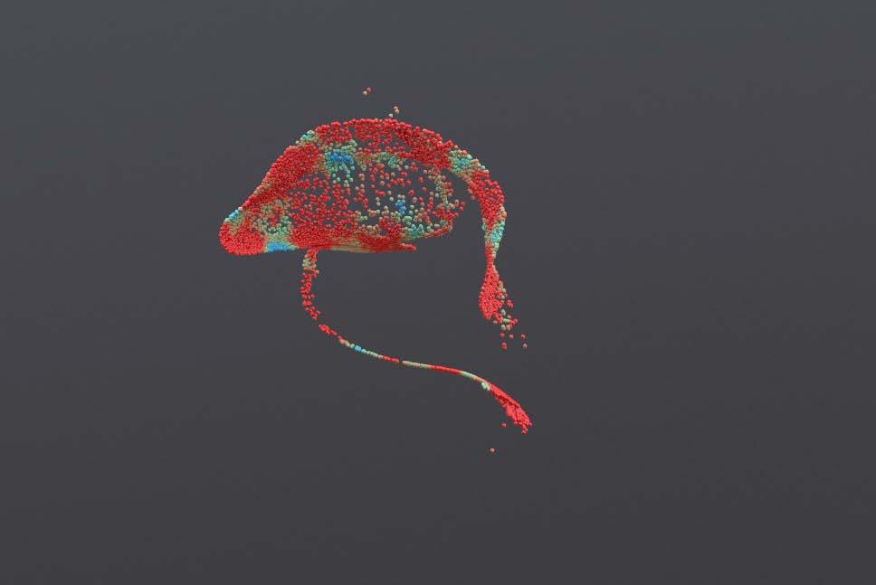
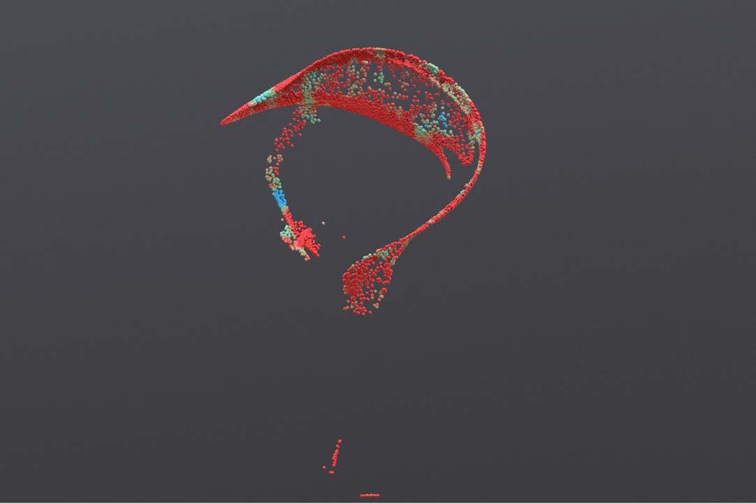
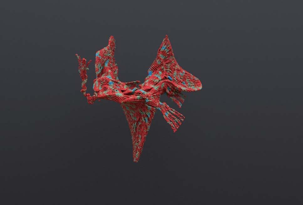
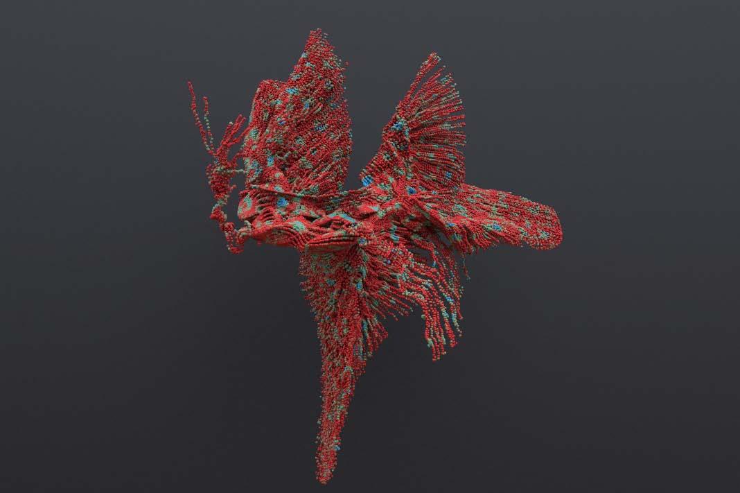
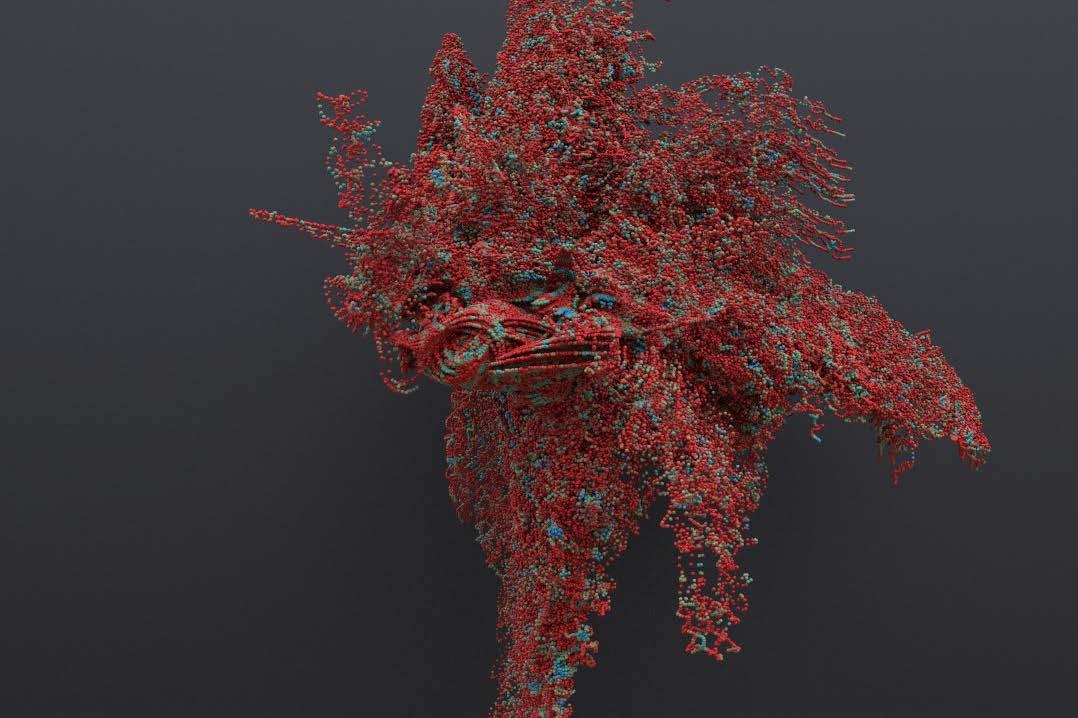
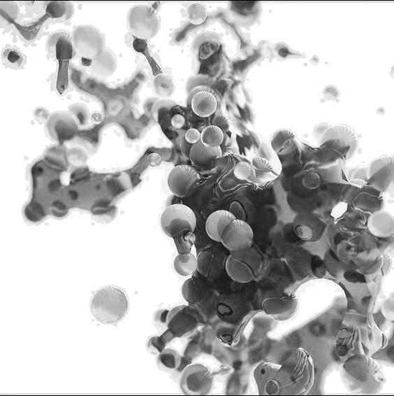
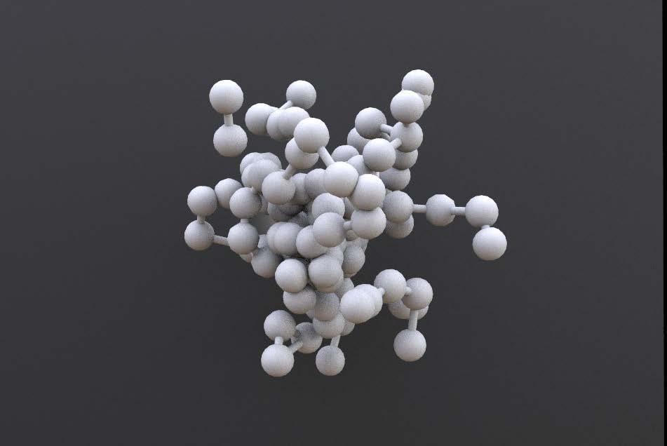
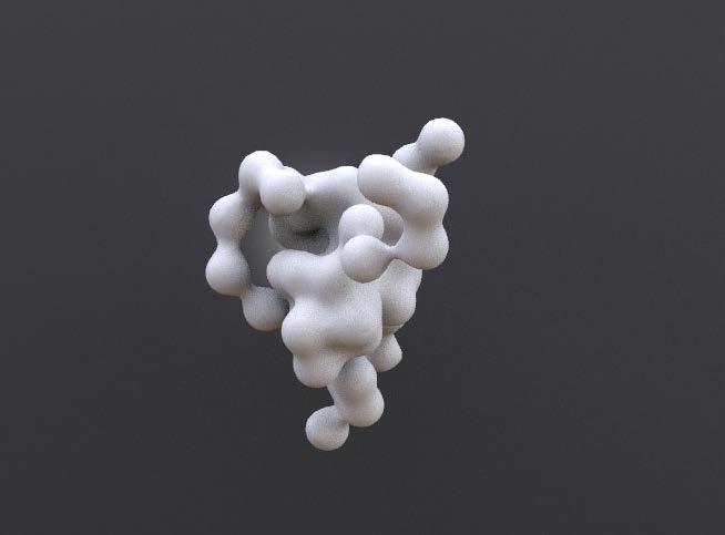
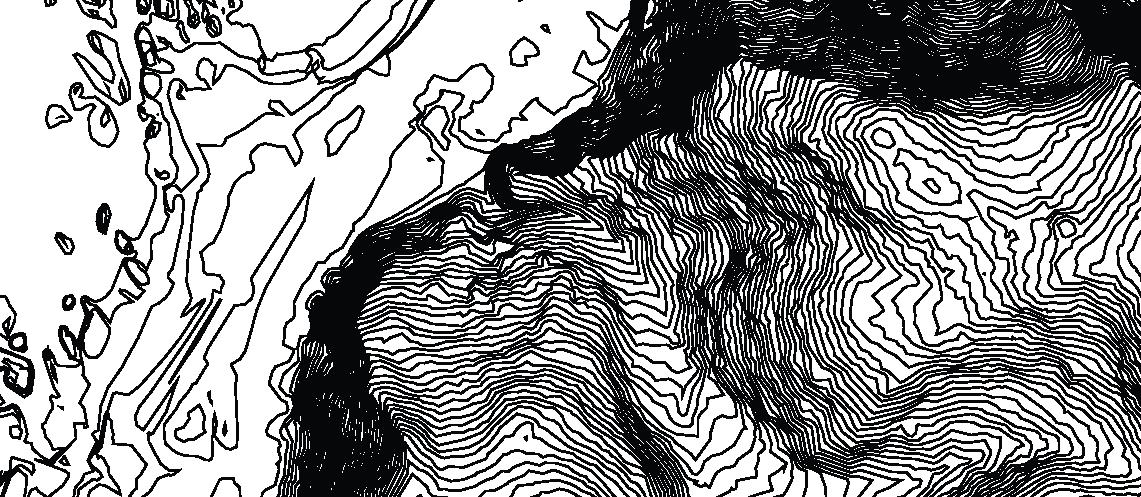
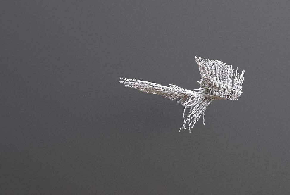
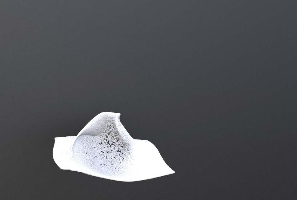
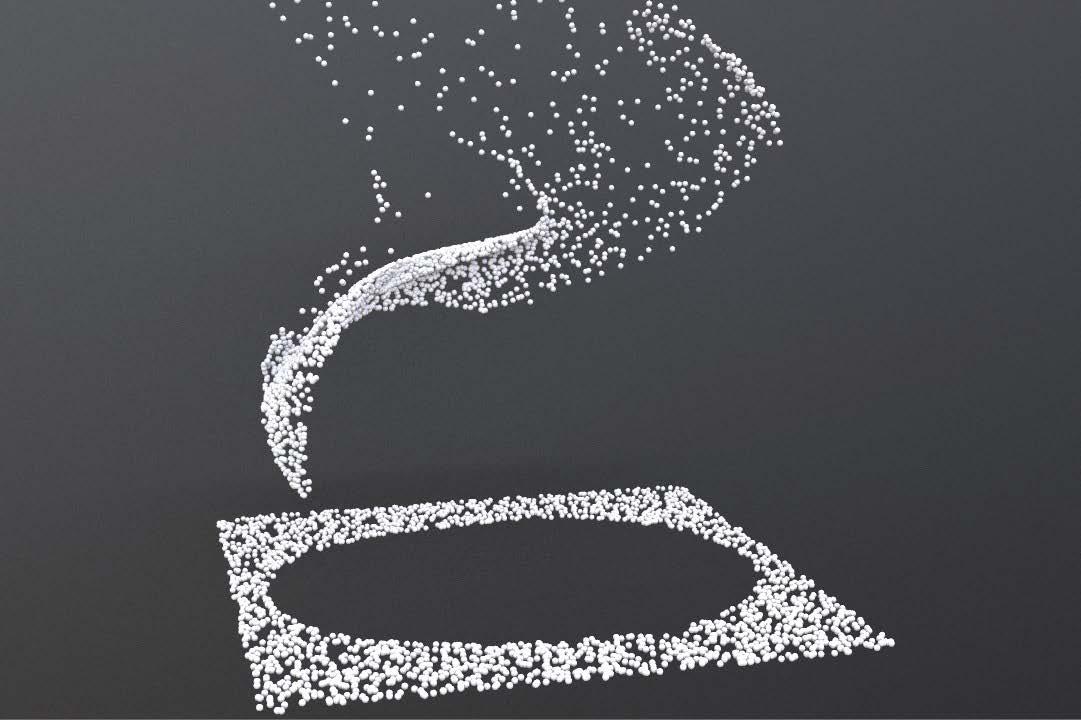
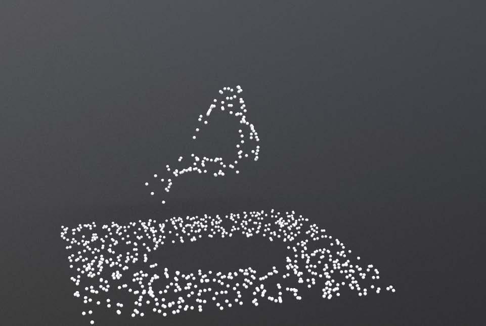
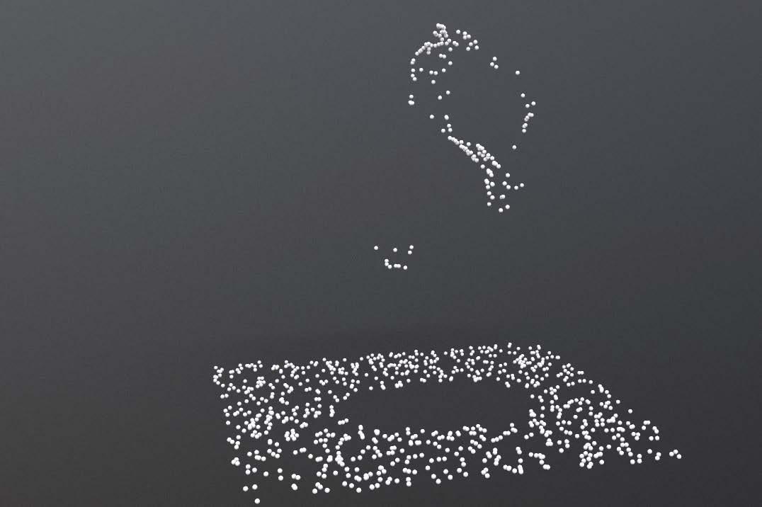
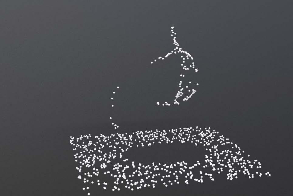
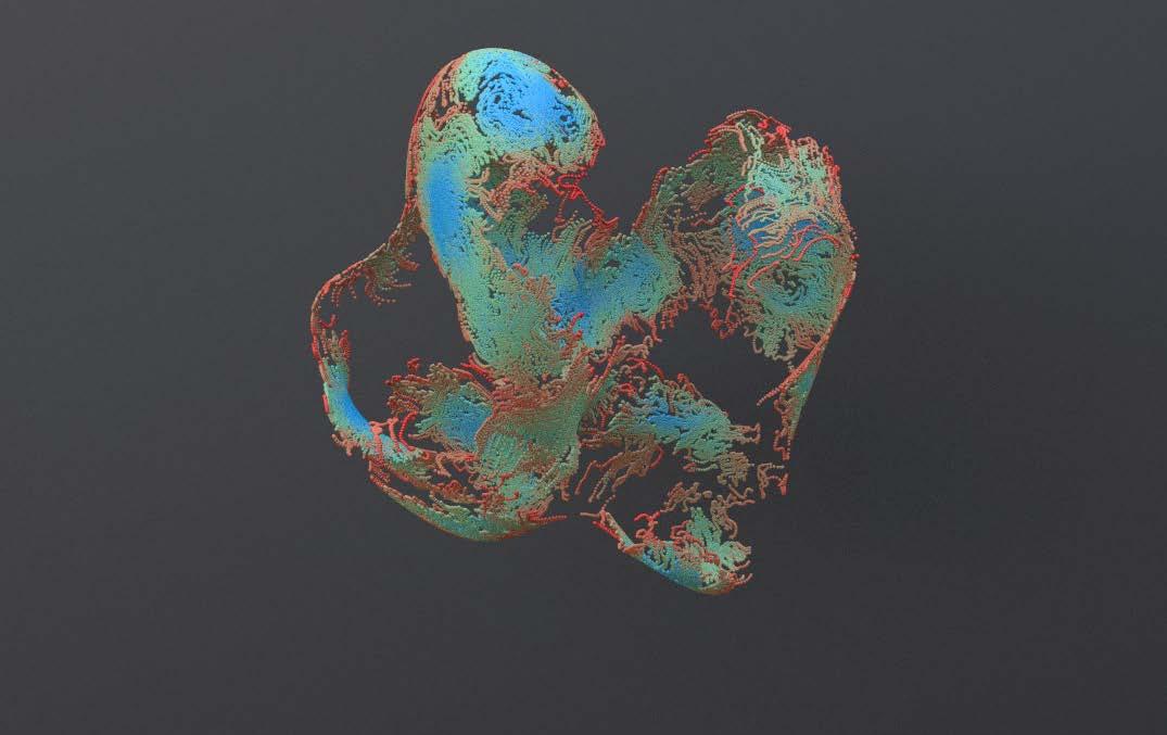
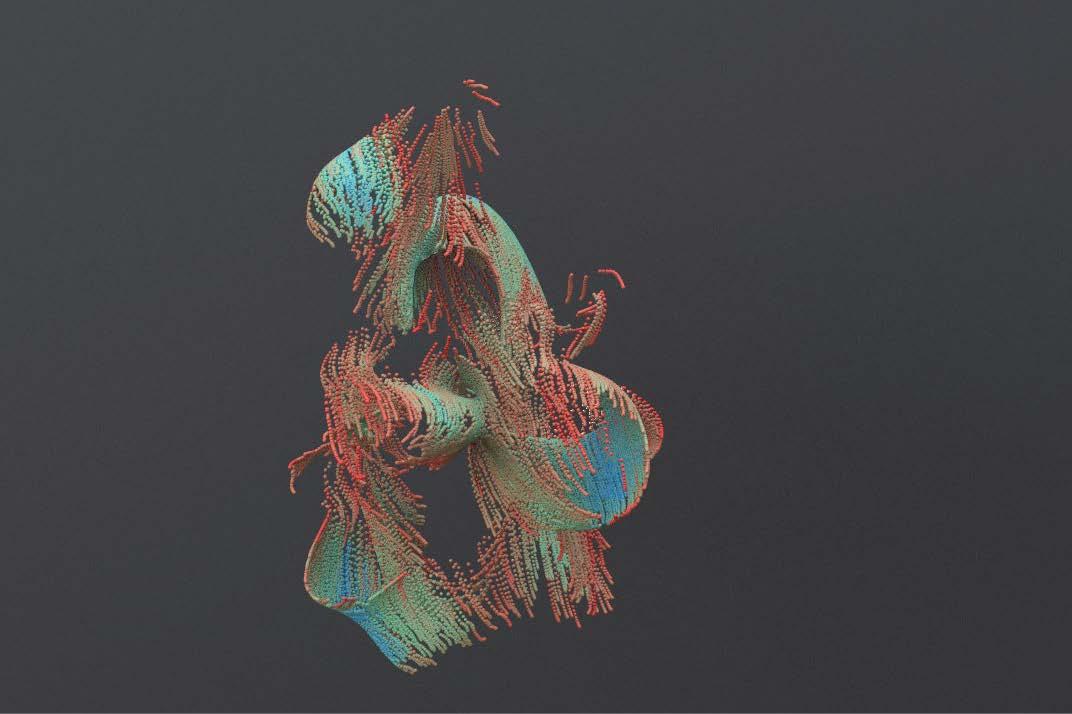
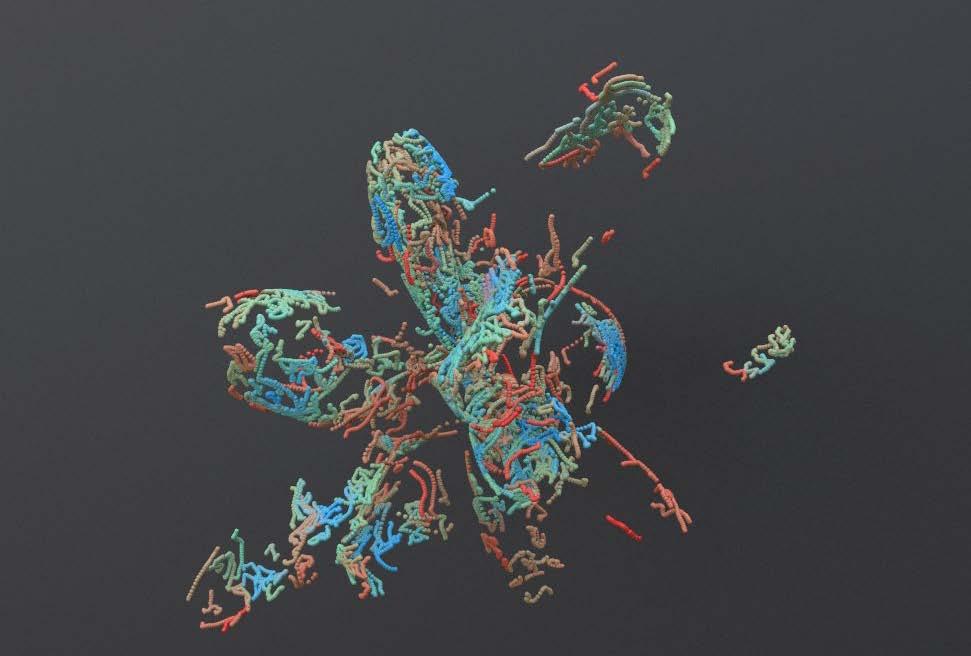
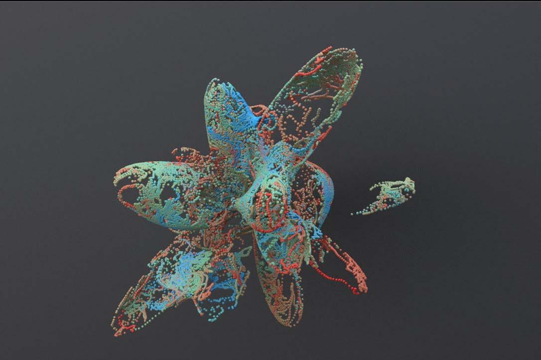
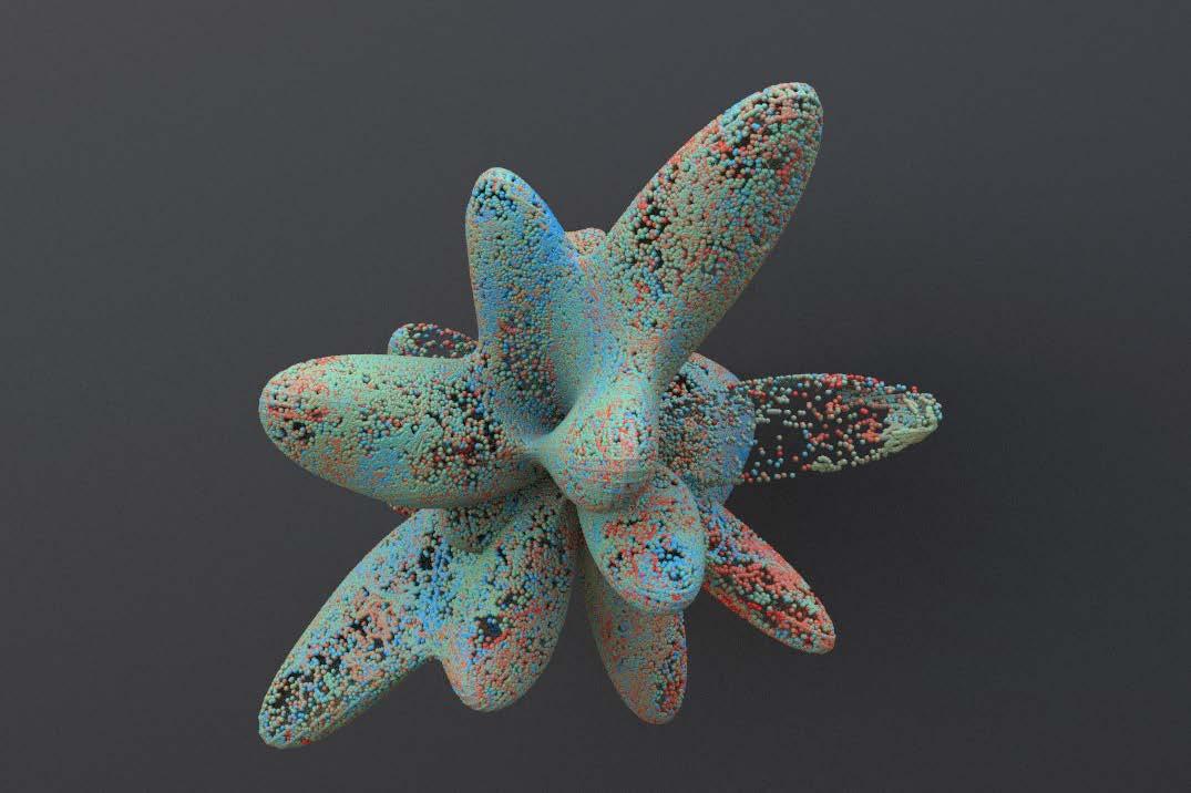
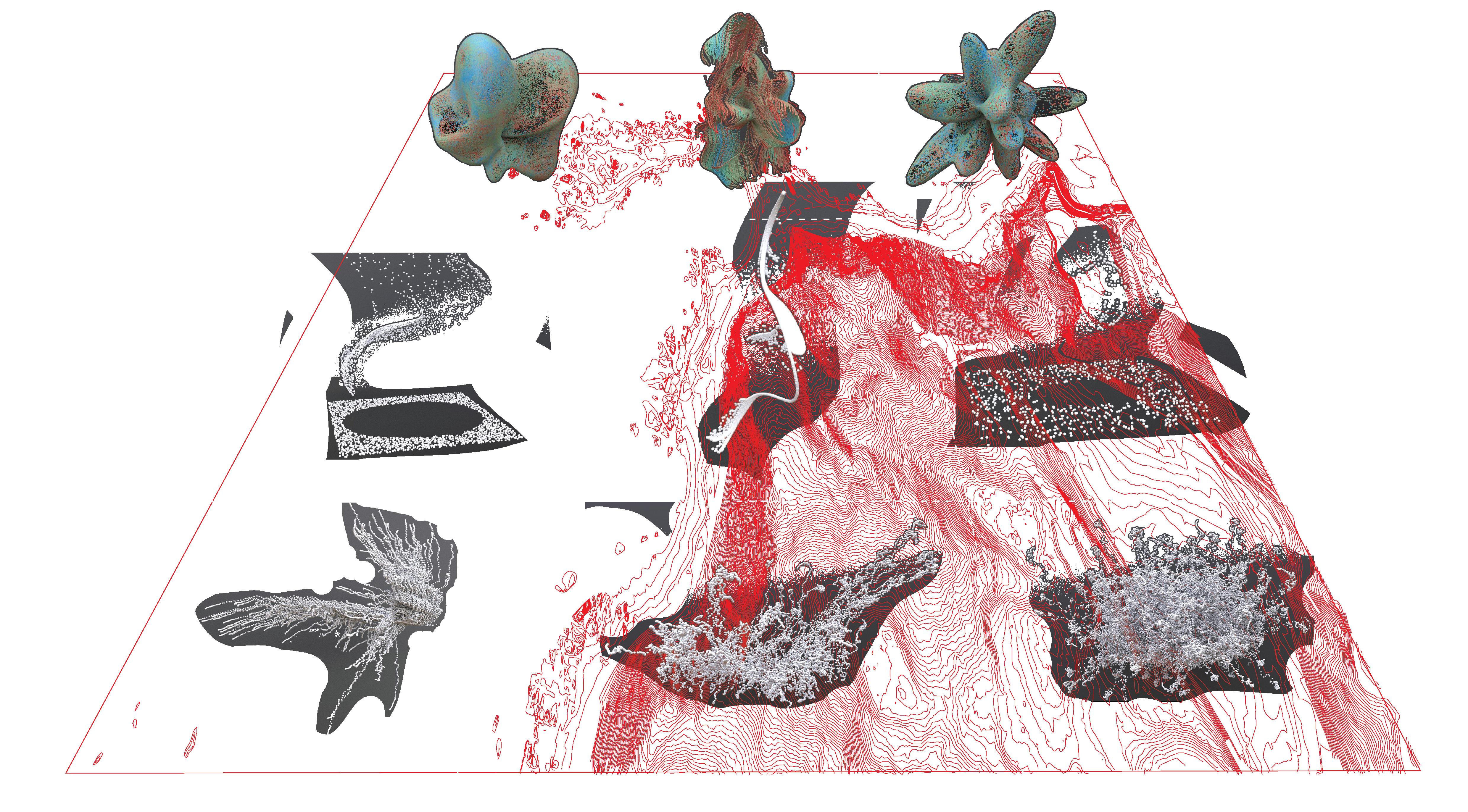
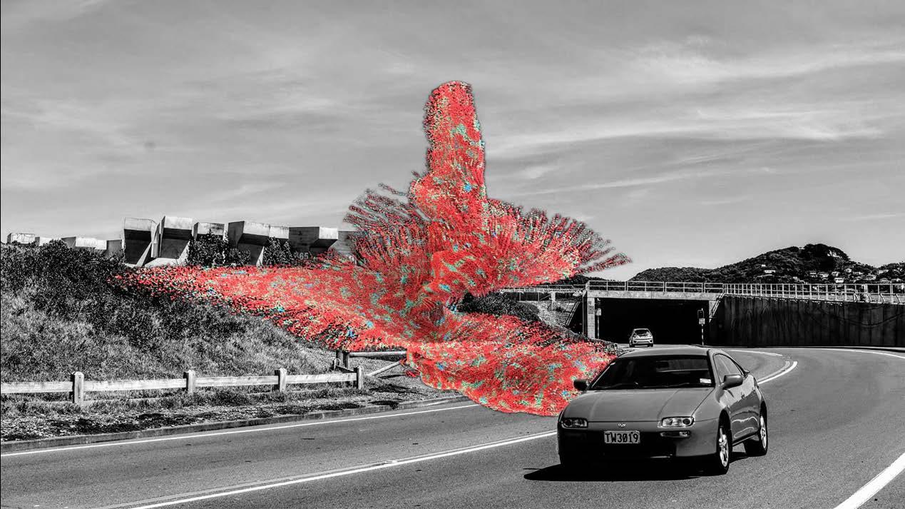
Conclusion and render
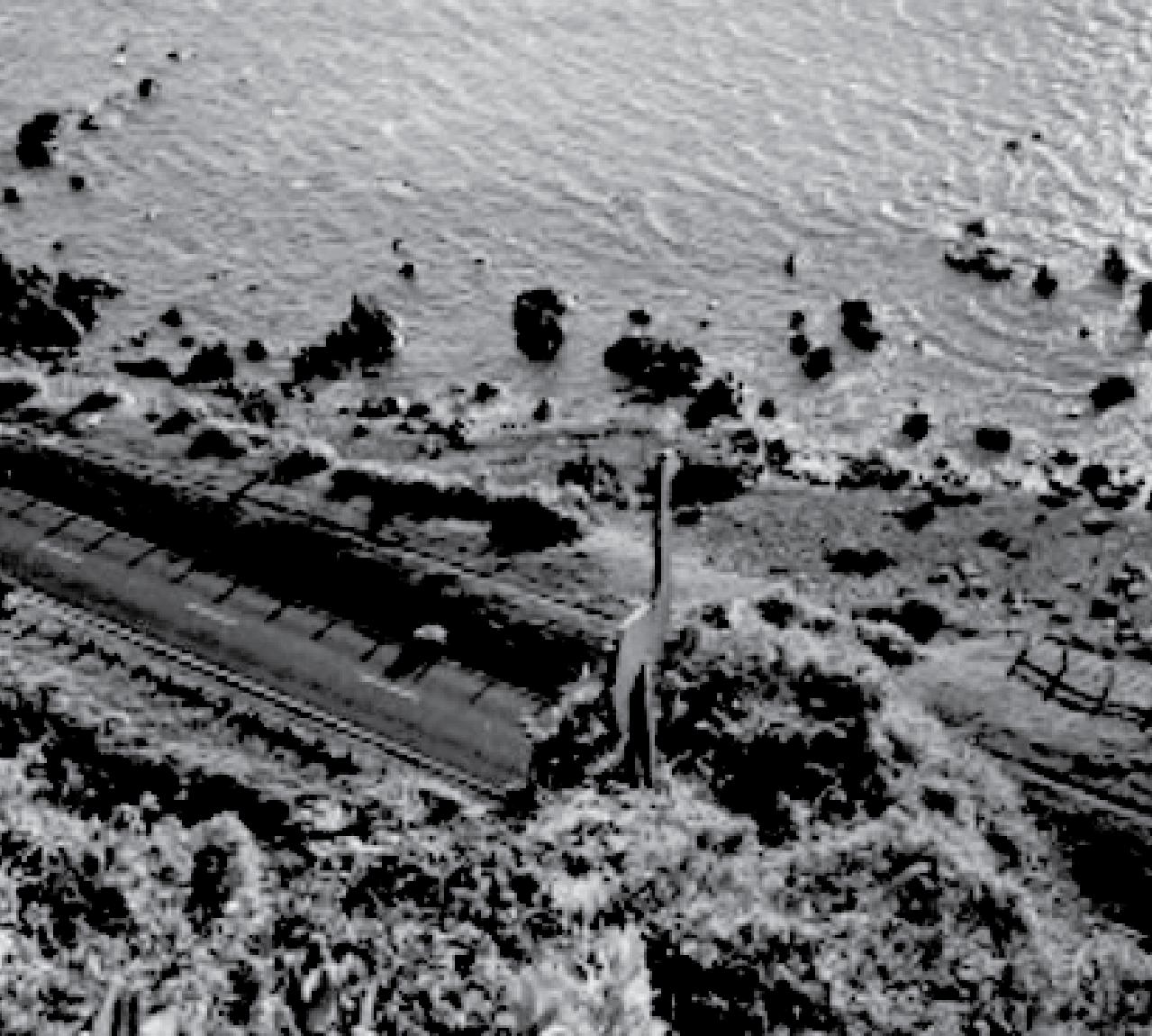
>> Project 2 explored computational methods in terms of replicating site context and generated multiple forms for concept development.
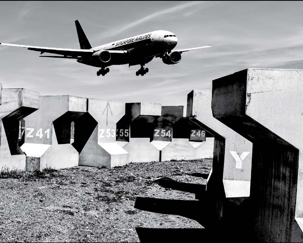
>> Render of Model H3- F150
>> Location: Motor way from Moa Point to Airport

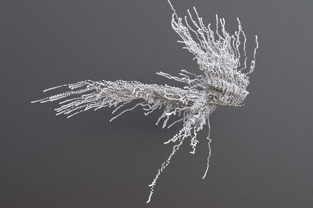
>> There are many forms that appear in the process of deformation are worthy of in-depth experiment. Increasing the control ability of the computational softwares will help to chieve a more accurate expression in many ways.
>> Site fabric is able to be digitalize and visualize by using computaional languages.
>> Next Ppoject is going to continue the journey of finding forms, and further develope forms to architectual concepts.