
INTRODUCTION
CHAPTER1
INTRODUCTION
1.1 Introduction
1.2 Project Brie
CHAPTER2
DESIGN AND COMMUNICATION:

SPECIAL INTEREST TECHNICAL RESEARCH STUDY
2.1 Preliminary schematic desi n
Architecturaldesi nwithtechnicalconsideration
Criticalandanalyticalthinkin ,withcreativedesi nsolvin capabilities

2.2 Research Methodolo y
CulturalContext
Mana ement,Practice&Law
Back roundo theStudy
LiteratureReview
ResearchMethodolo y
2.3 Review
2
INTRODUCTION
CHAPTER3
CULTURAL CONTEXT
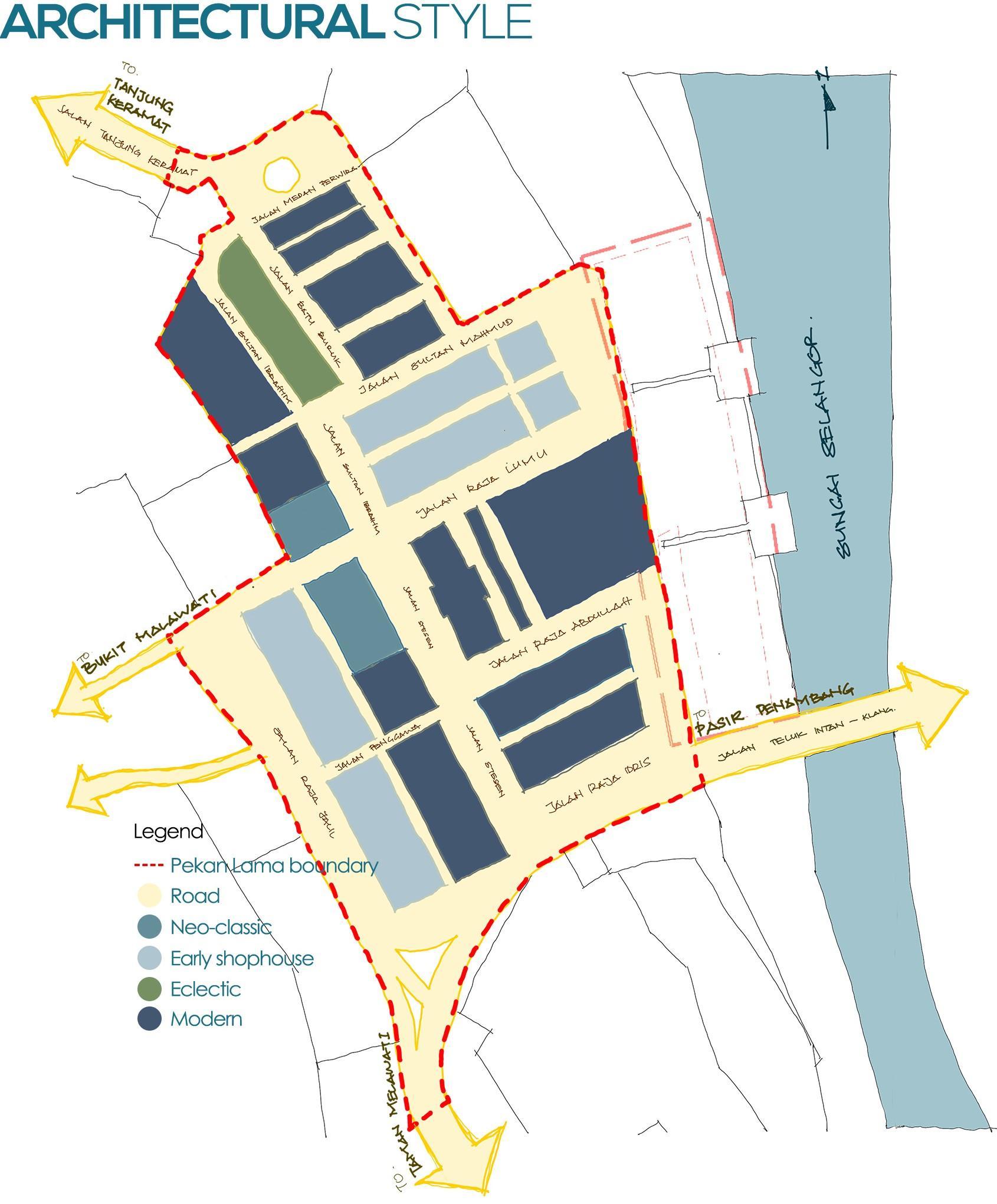
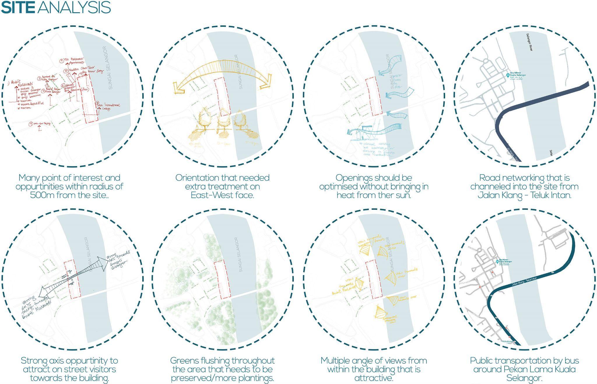
3.1 Urban Element
Siteanalysiso UrbanDesi nElements
Paths,nodes,landmarks,districtsanded es
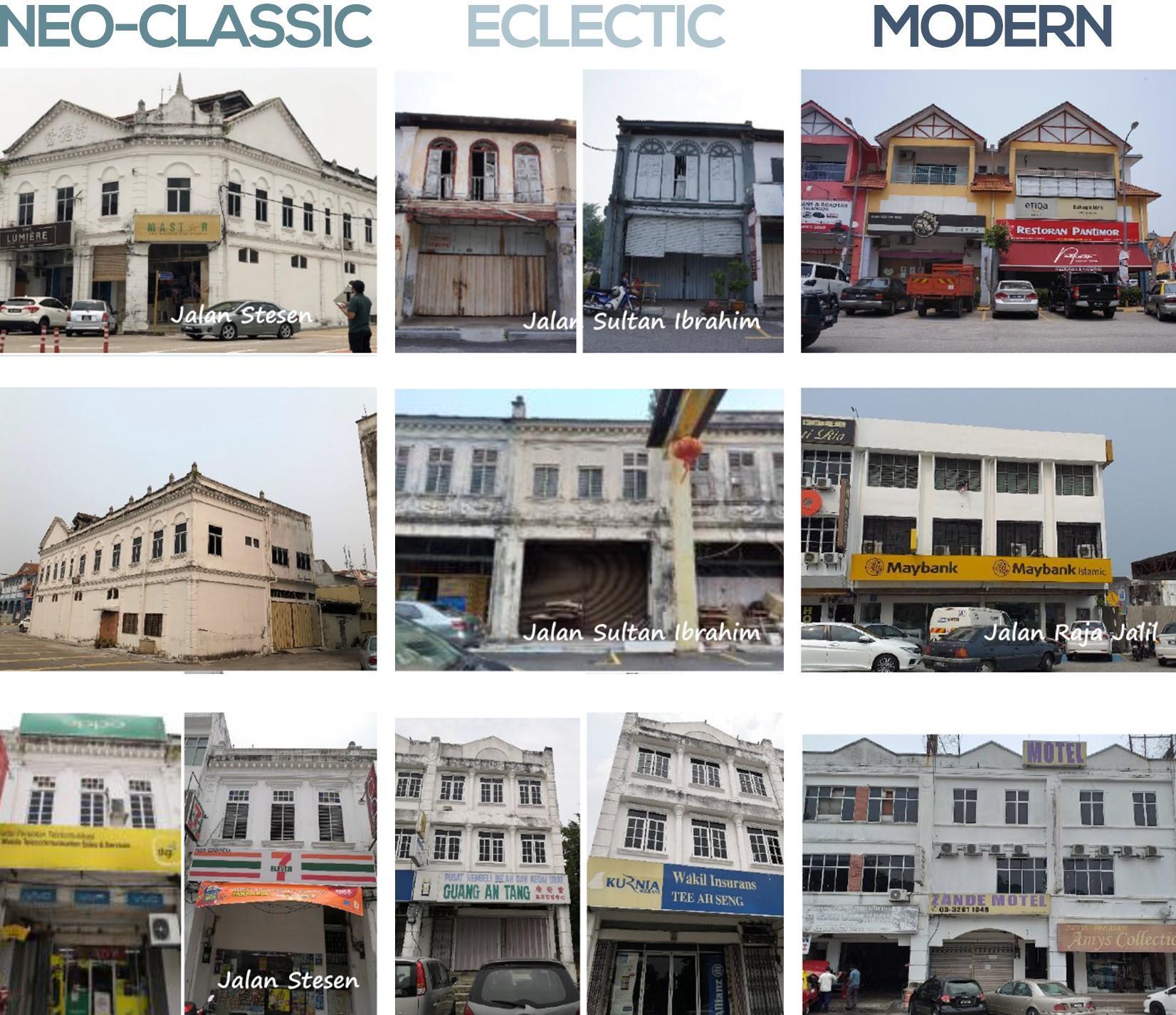
3.2 Architectural Critics
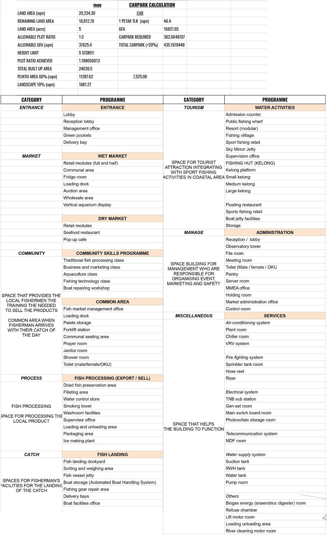
Buildin Typolo y&Scheduleo Accommodation
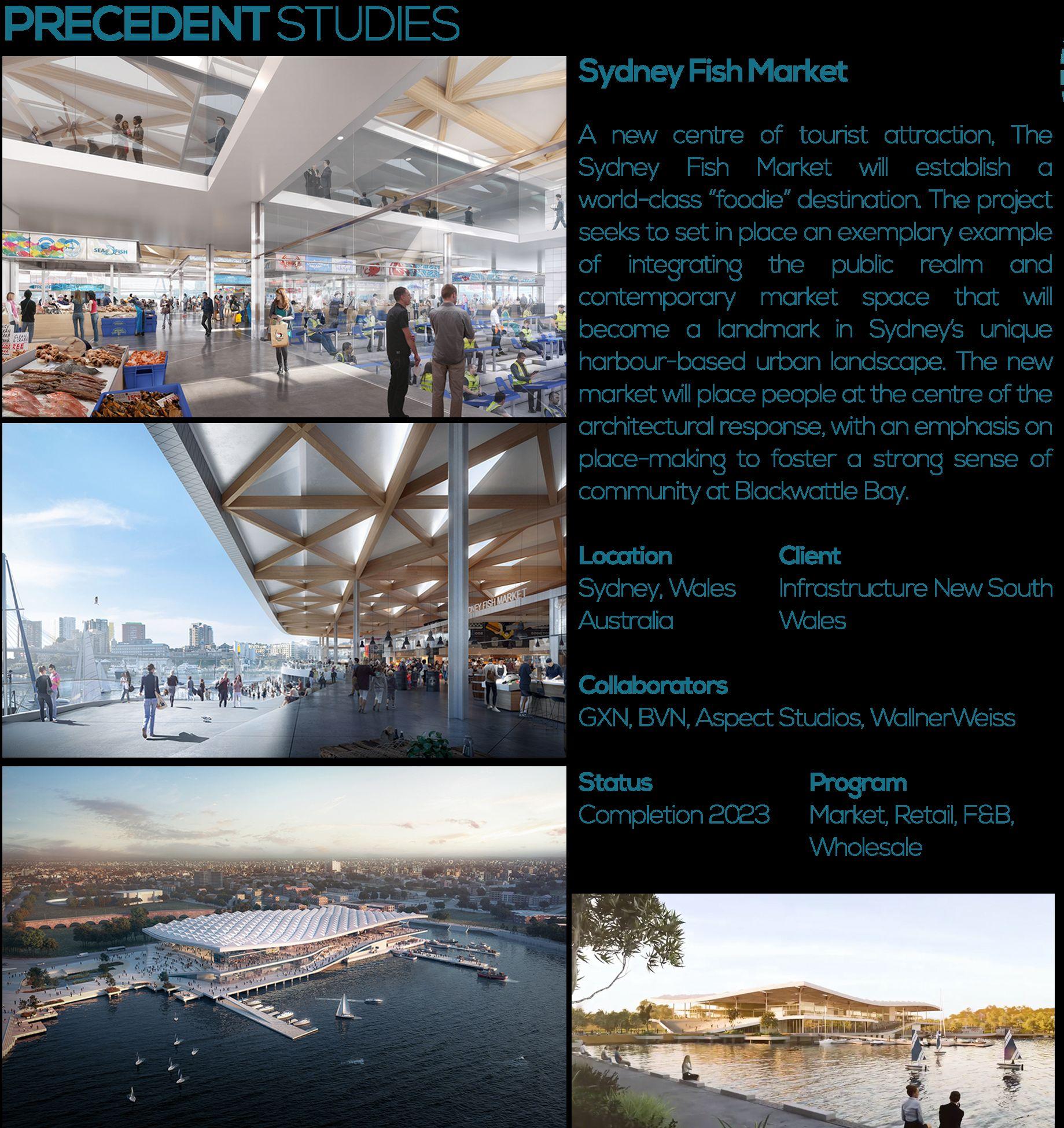
PrecedentStudy
3.3 Review
CHAPTER4
TECHNOLOGY AND ENVIRONMENT
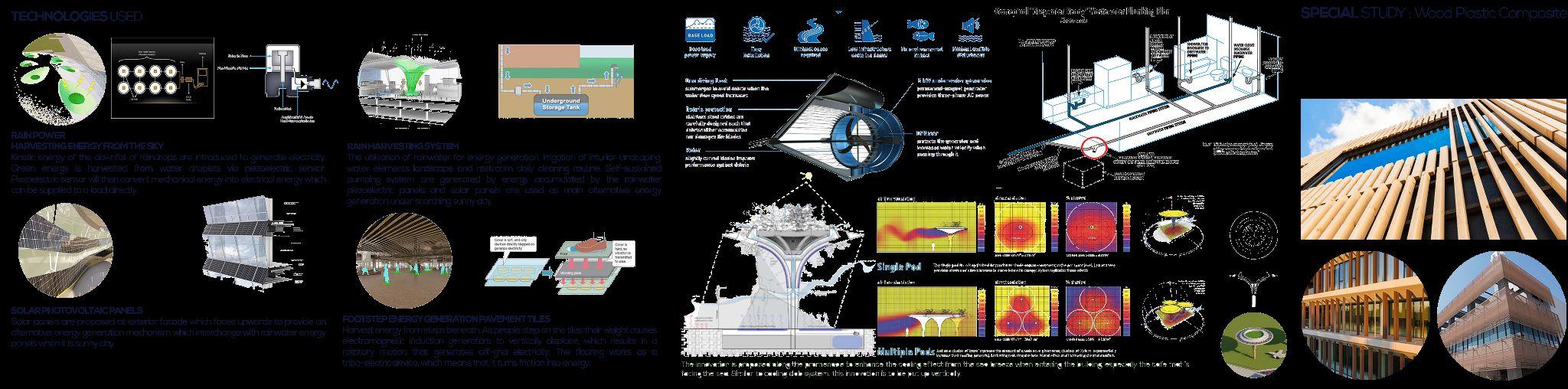
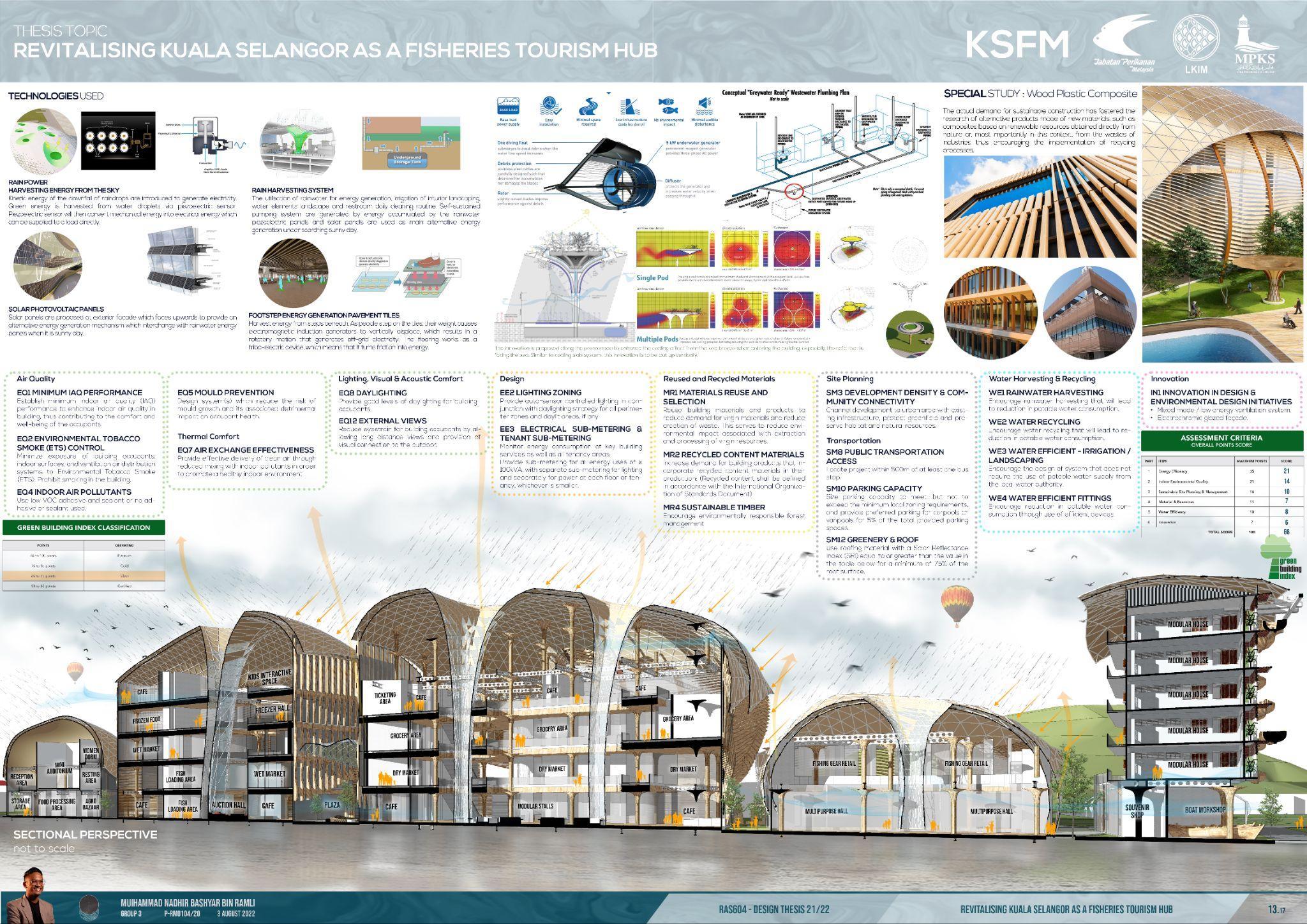
4.1 Ener y Efficient Buildin Desi n Technolo y Environmentalissues,Ener yinbuildin
Efficiencyandener y GreenBuildin Index
Passivestrate y
4.2 BIM Inte ration In Architecture
BIMToolsusedlikeAutoCADandSketchUp
4.3 Buildin Technolo y Inte ration
Buildin Technolo y,buildin structuralsystem,fireSaety
Buildin servicessystem,HVAC&relatedM&E
Automationsystemandintelli ent/smartbuildin s
4.4 Review
CHAPTER5 MANAGEMENT, PRACTICE AND LAW
5.1 Housin Re ulations And Practice
Existence,roleandresponsibilitieso Developers
LawandLocalAuthorityRequirements
5.3 Review
CHAPTER6
CONCLUSION
6.1 Introduction
6.2 Final Architecture Desi n
3
BUILDING TITLE
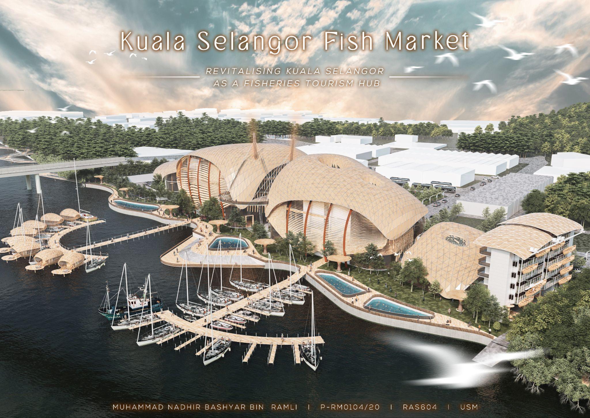
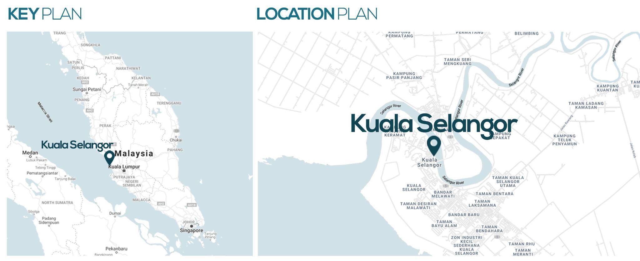
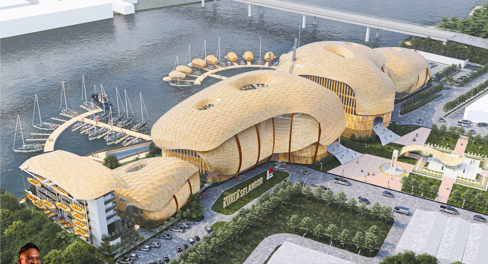
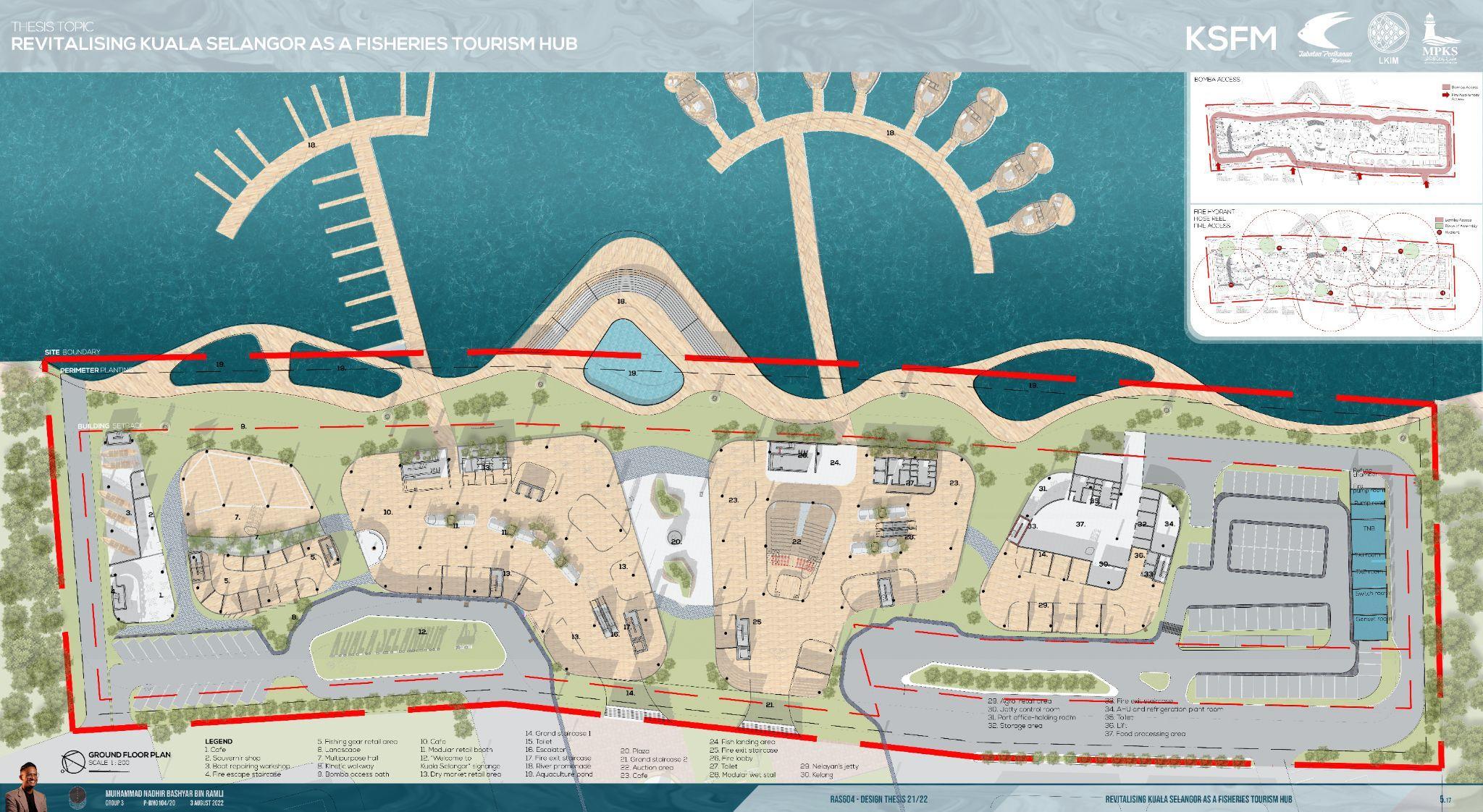
ProposedaKualaSelangorFishMarketatLot1440,Jalan Abdullah,45000,KualaSelangor
OWNER
LembagaKemajuanIkanMalaysia
BRIEF
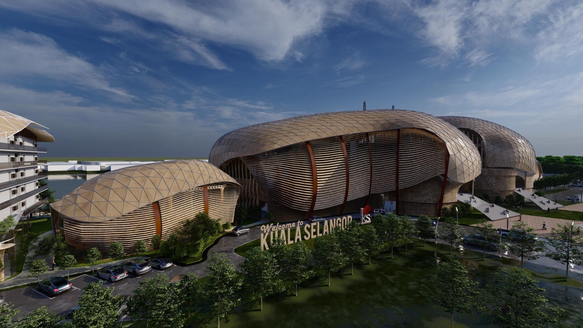
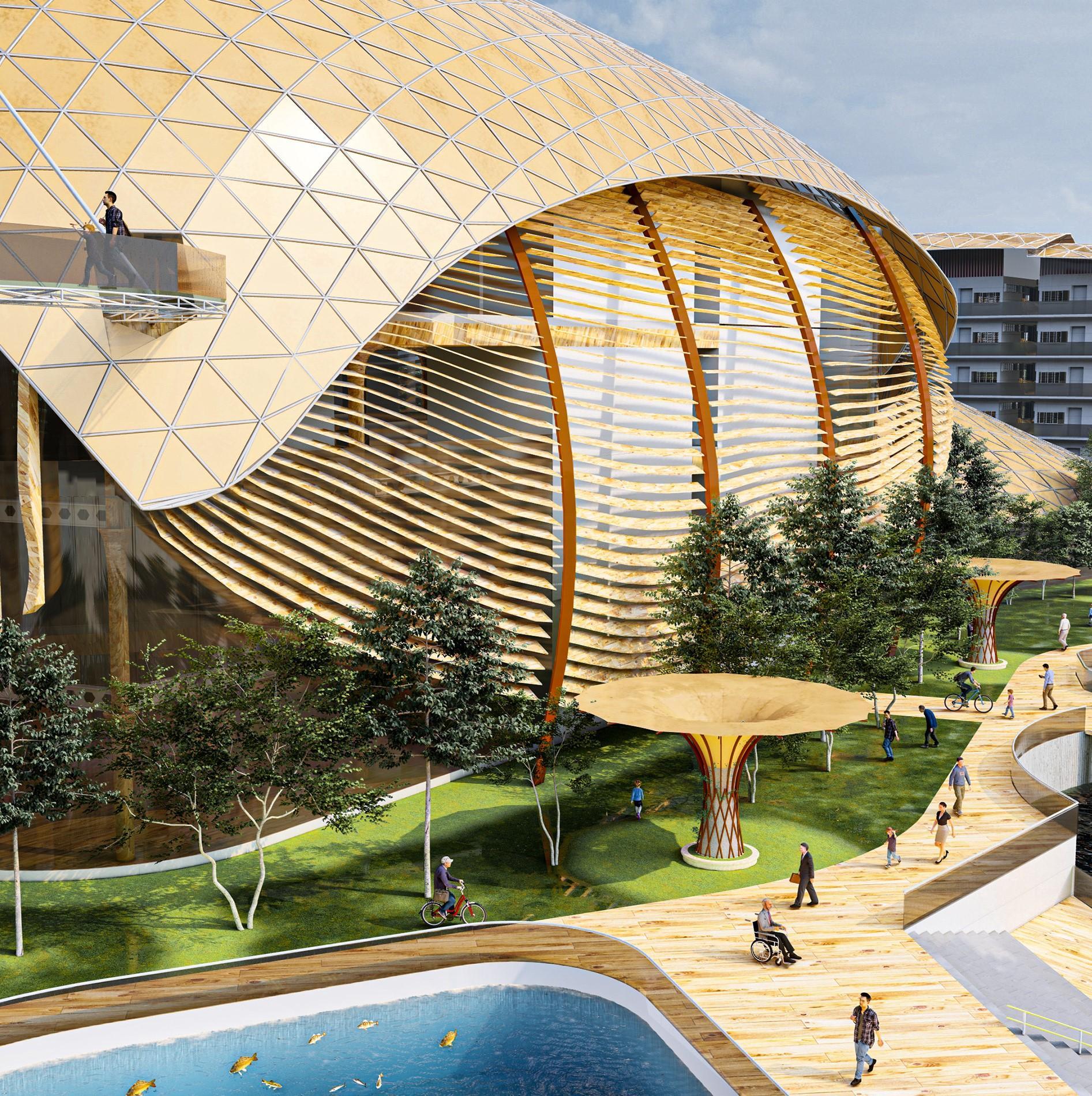
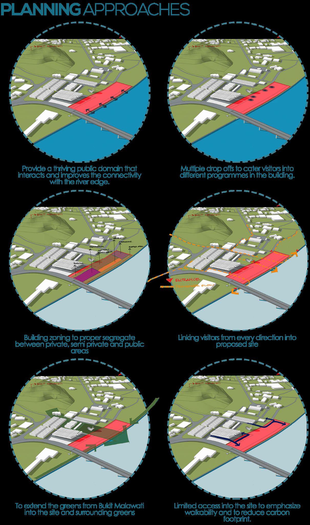
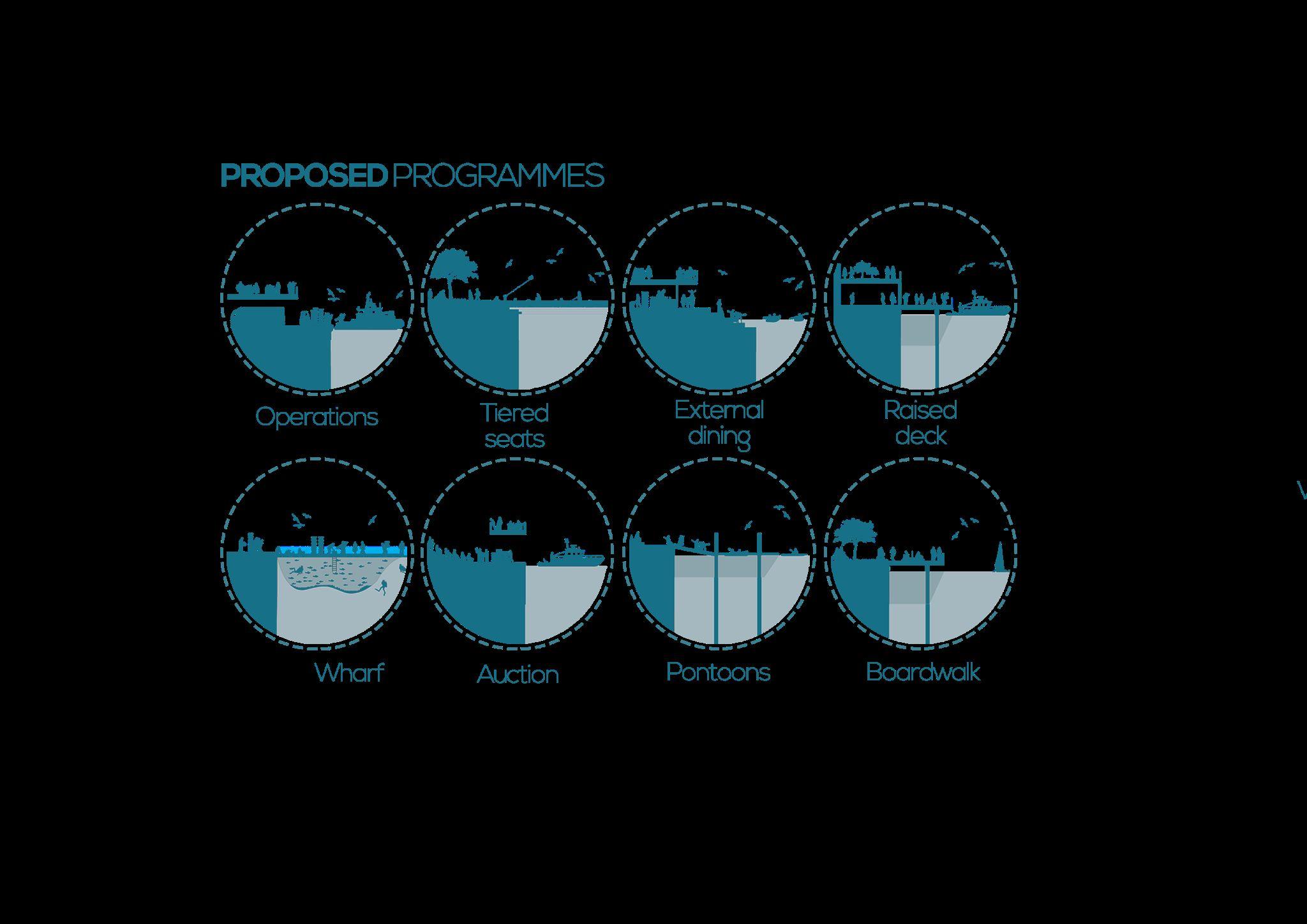
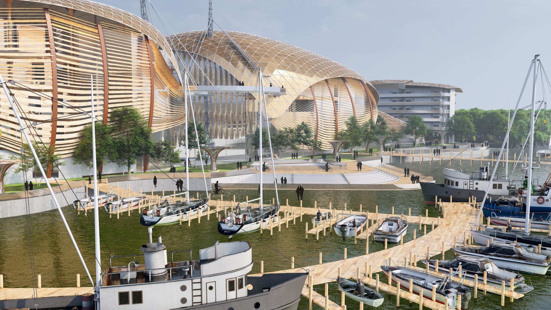
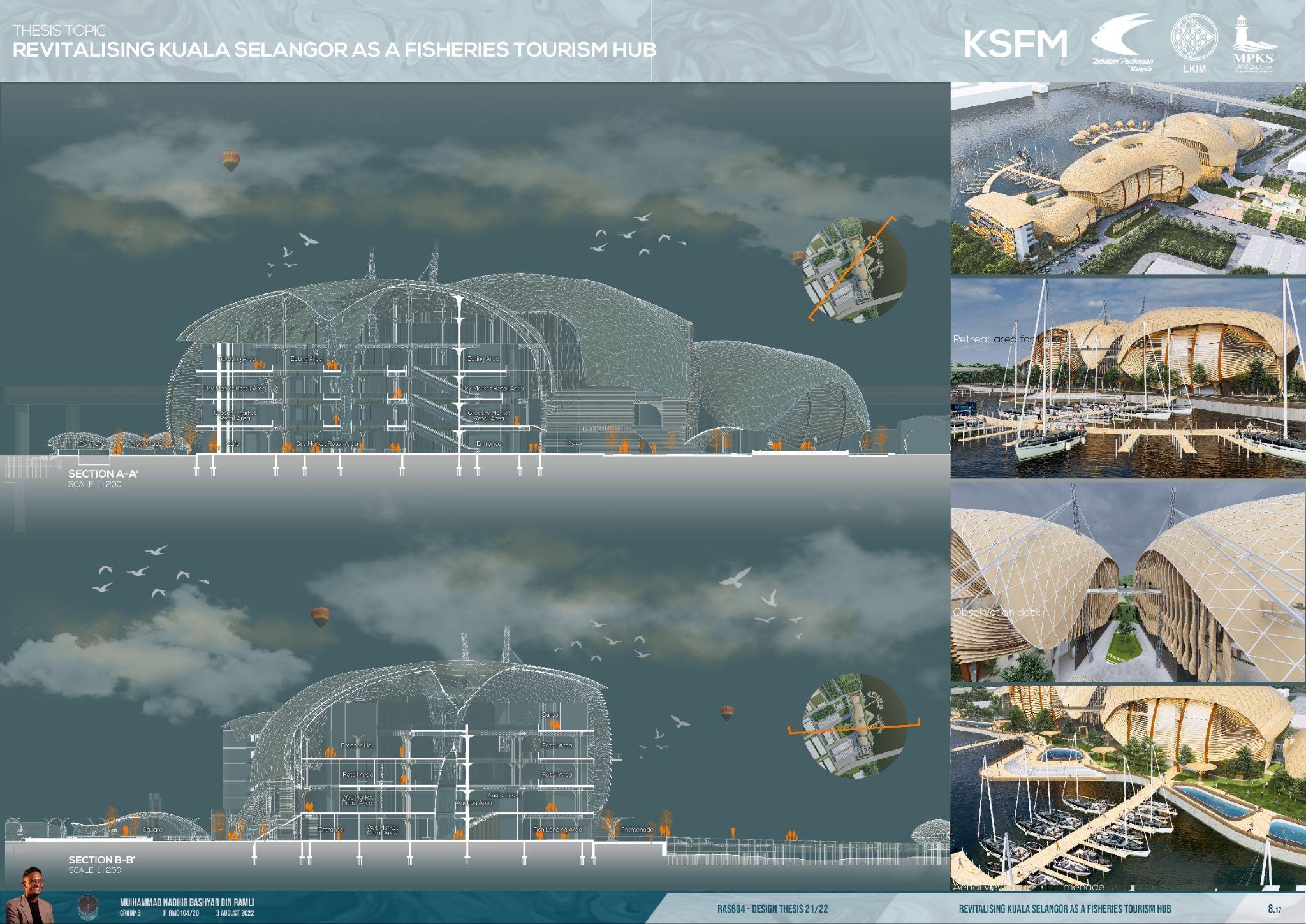
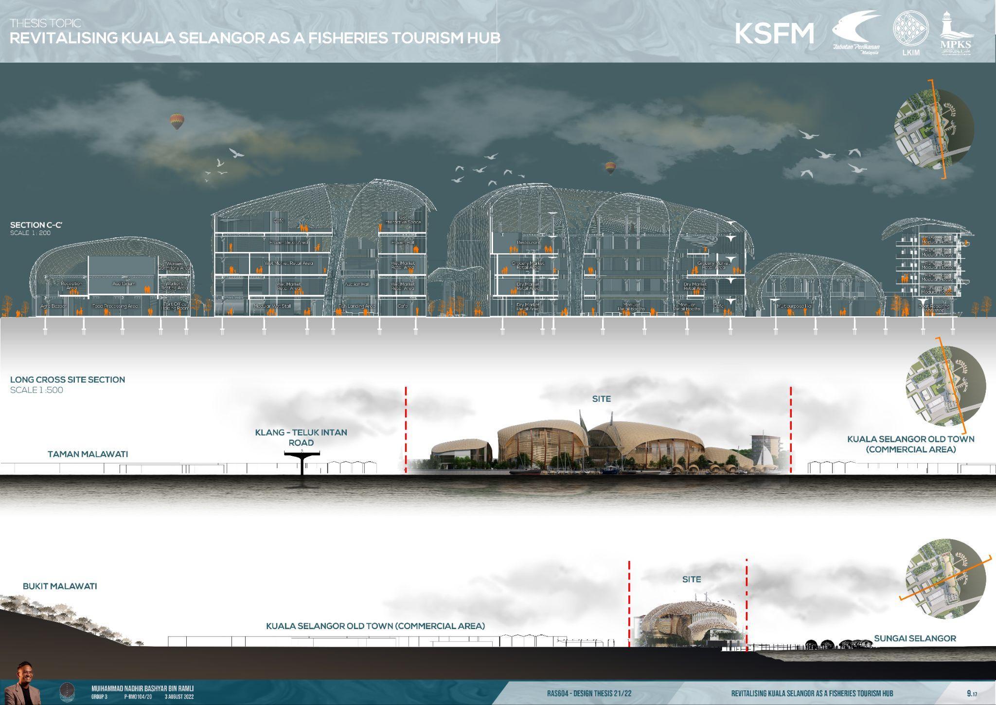
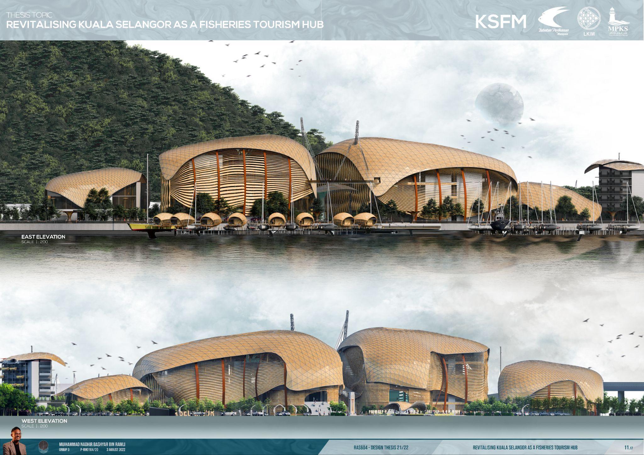
The brief is to revitalise Kuala Selangor Fish Market and create a tourism and a go-to destination in the suburbs that will be dynamic, sustainable, and sympathetic to the local area and it will become a strategic market, "foodie" and an Instagrammable destination. The project aims to create a model for integrating the public realm and contemporary market space that will become a landmark in Kuala Selangor distinctive tourism landscape. People will be at the centre of the architectural response for the new market, with an emphasis on placemaking to foster a strong sense of community at Kuala Selangor Old Town, Tanjung Keramat and Taman Malawati. Combines the traditional working market programme with modern features and is intended to create a strong public connection to the waterfront. The organic roof form keeps the essence of this typology while also creating a modern iconforthewaterfront.
4
CHAPTER1
INTRODUCTION

6
7

8 DEMOGRAPHY
9

10
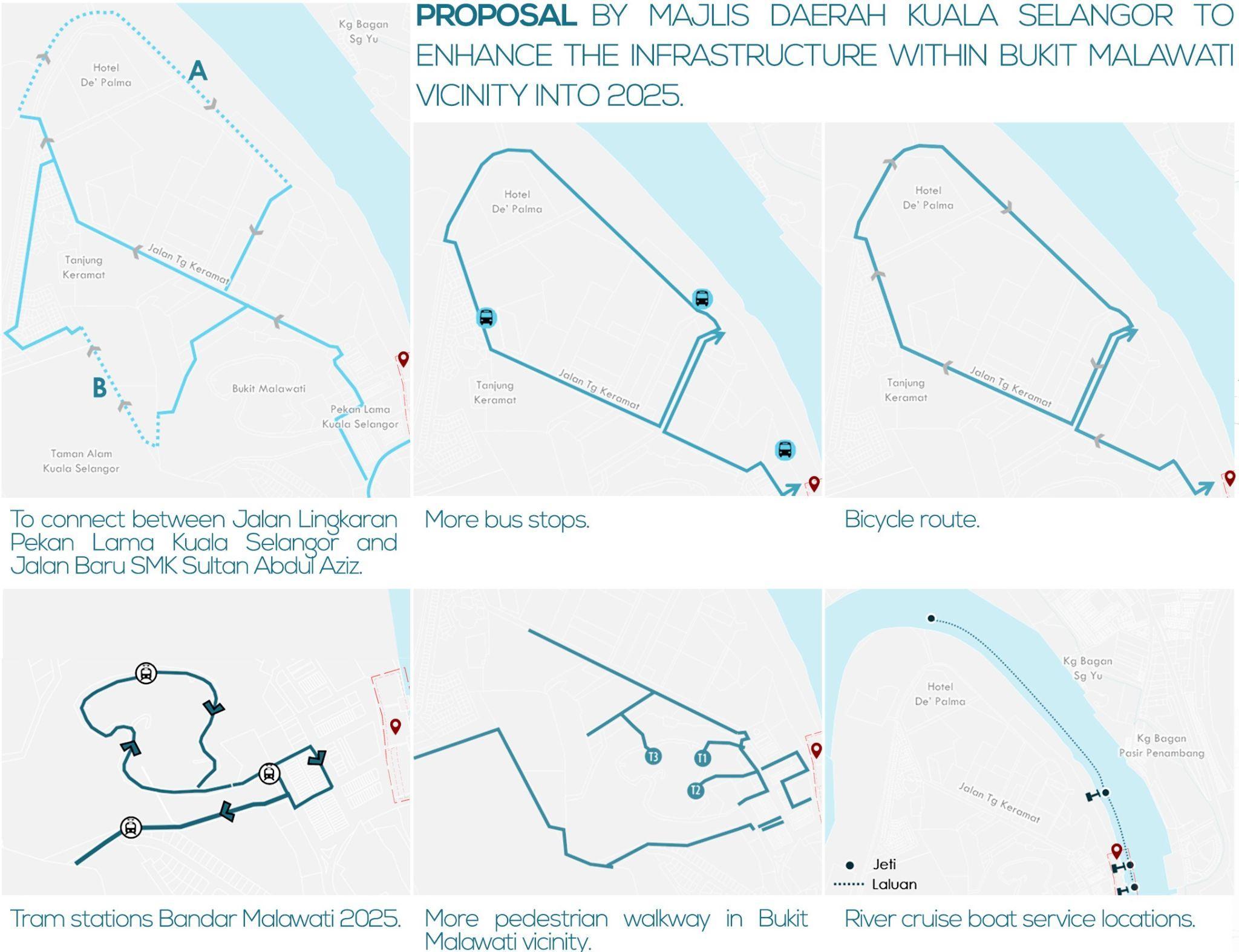
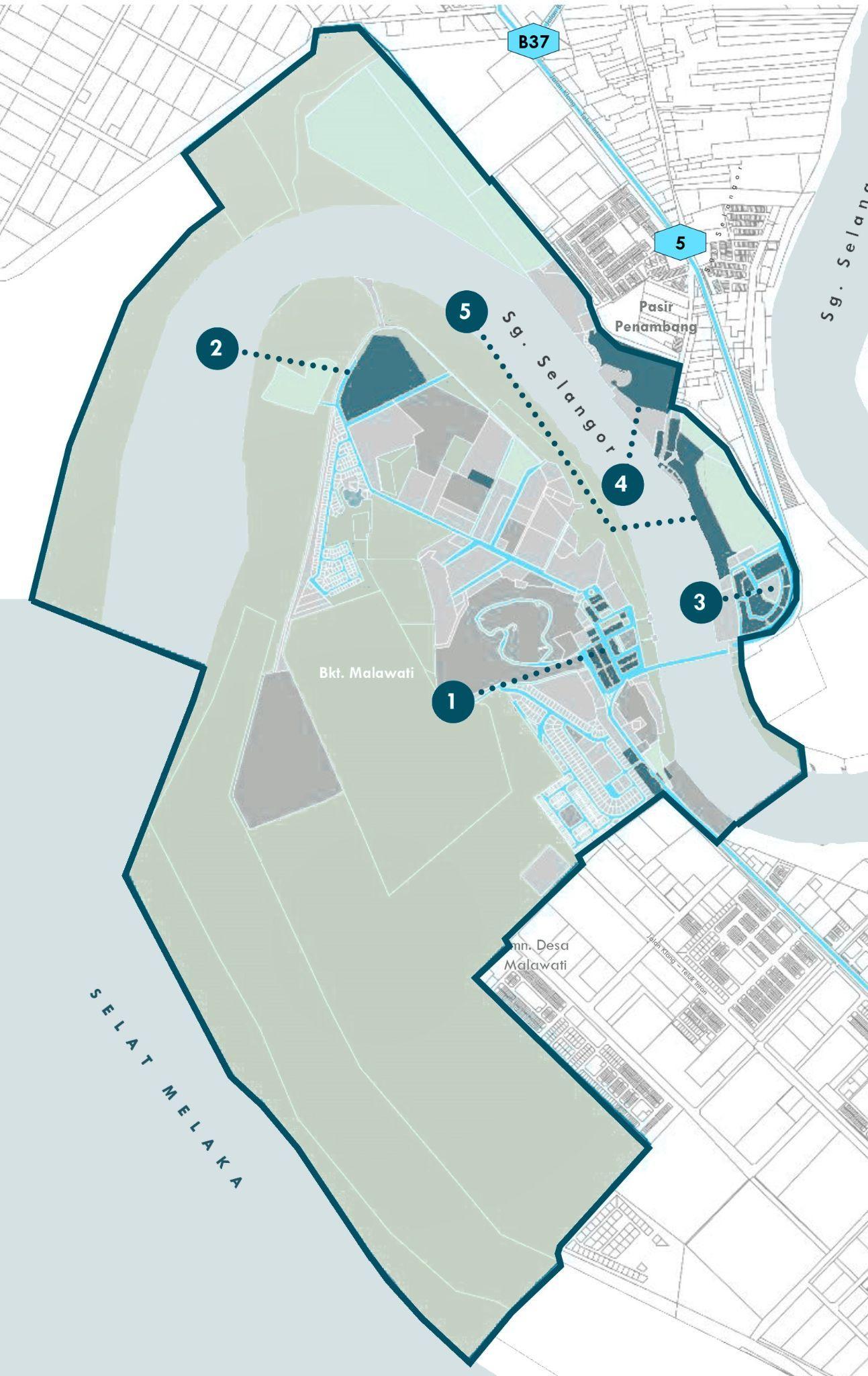
REACHABILITY

13 CHAPTER2 DESIGN AND COMMUNICATION

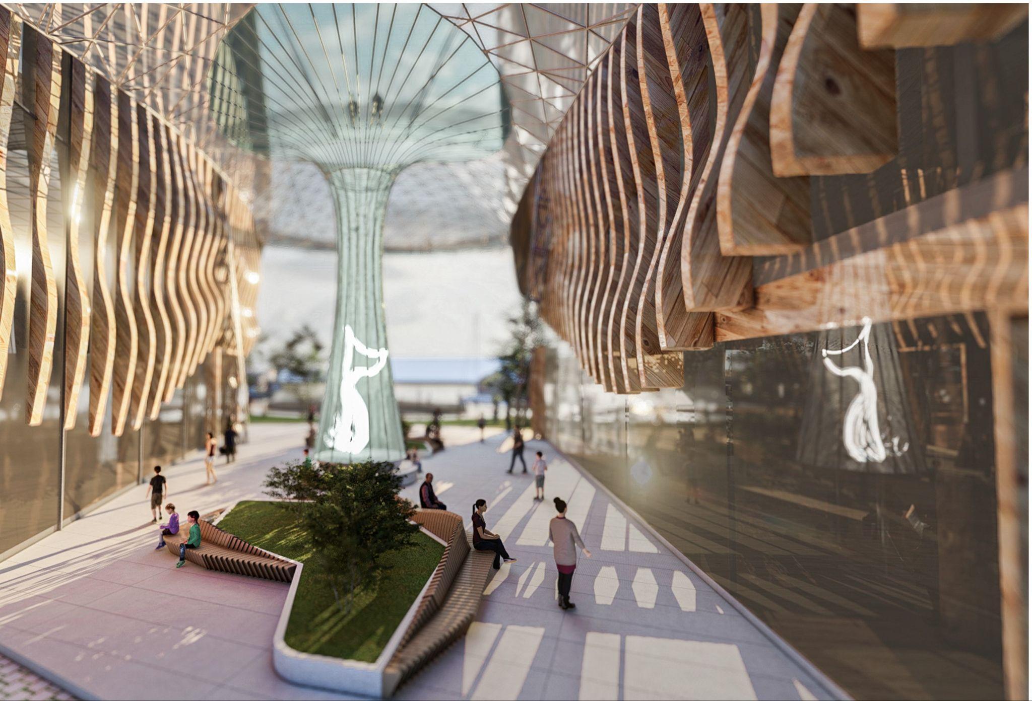
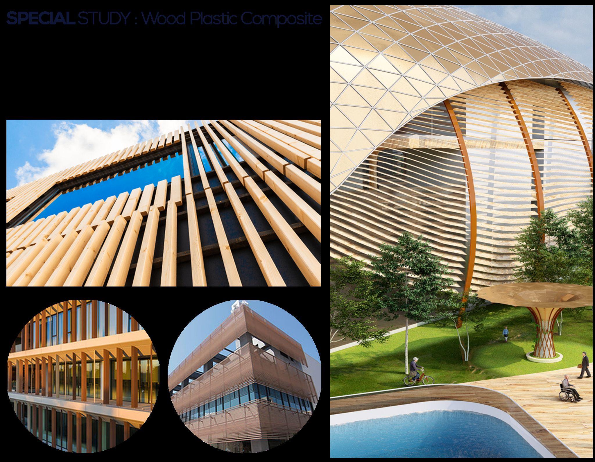
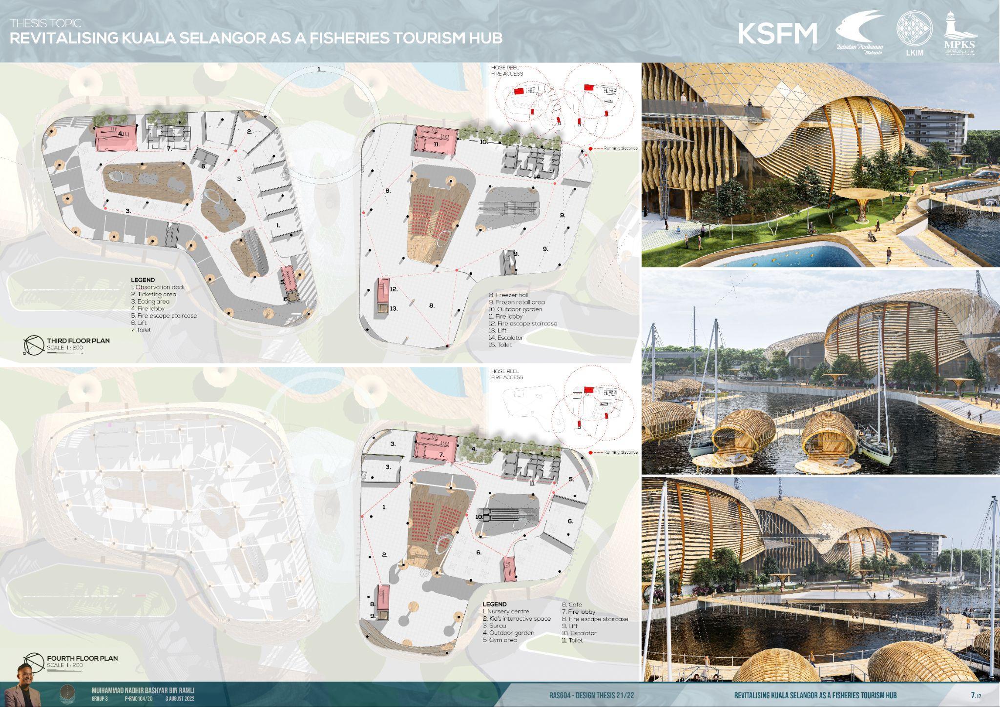
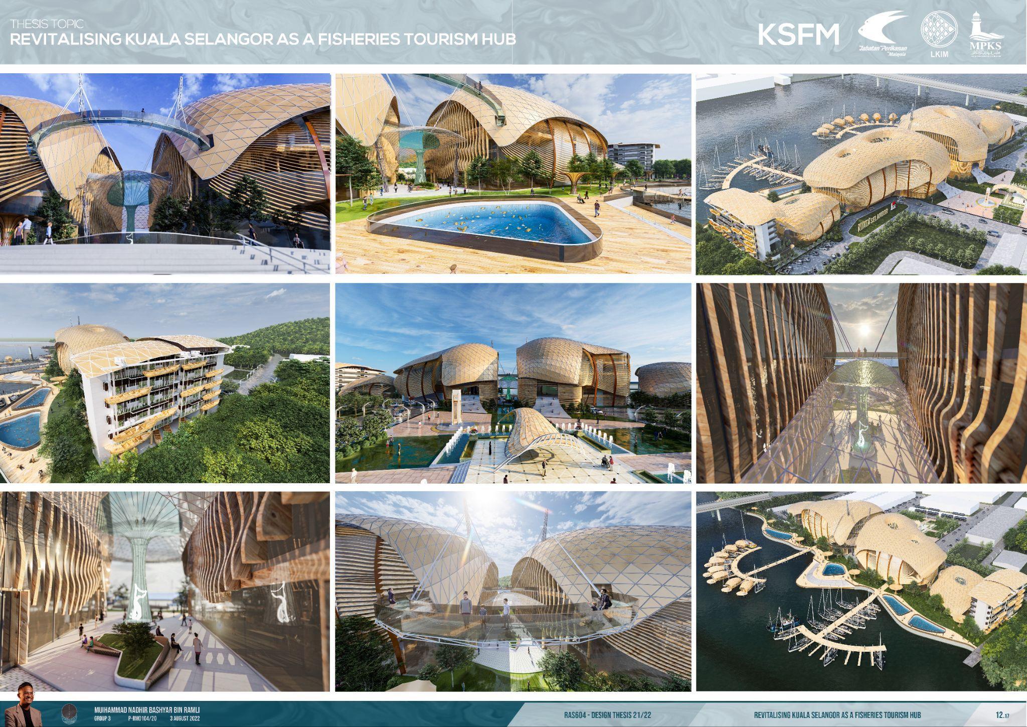
PLAZA INTERIOR WITH TREE-LIKE COLUMNS
14
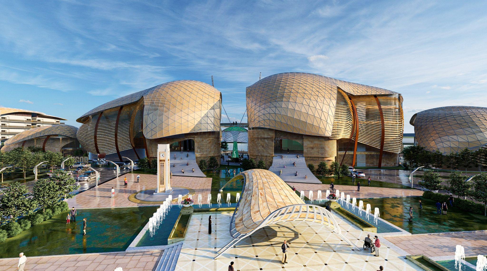
AERIAL VIEW CENTRAL
PLANTER BOX
INITIAL SKETCHES


15

16

18
20
CHAPTER3 CULTURAL CONTEXT
23


25 SITE PHOTOS
ABSTRACT

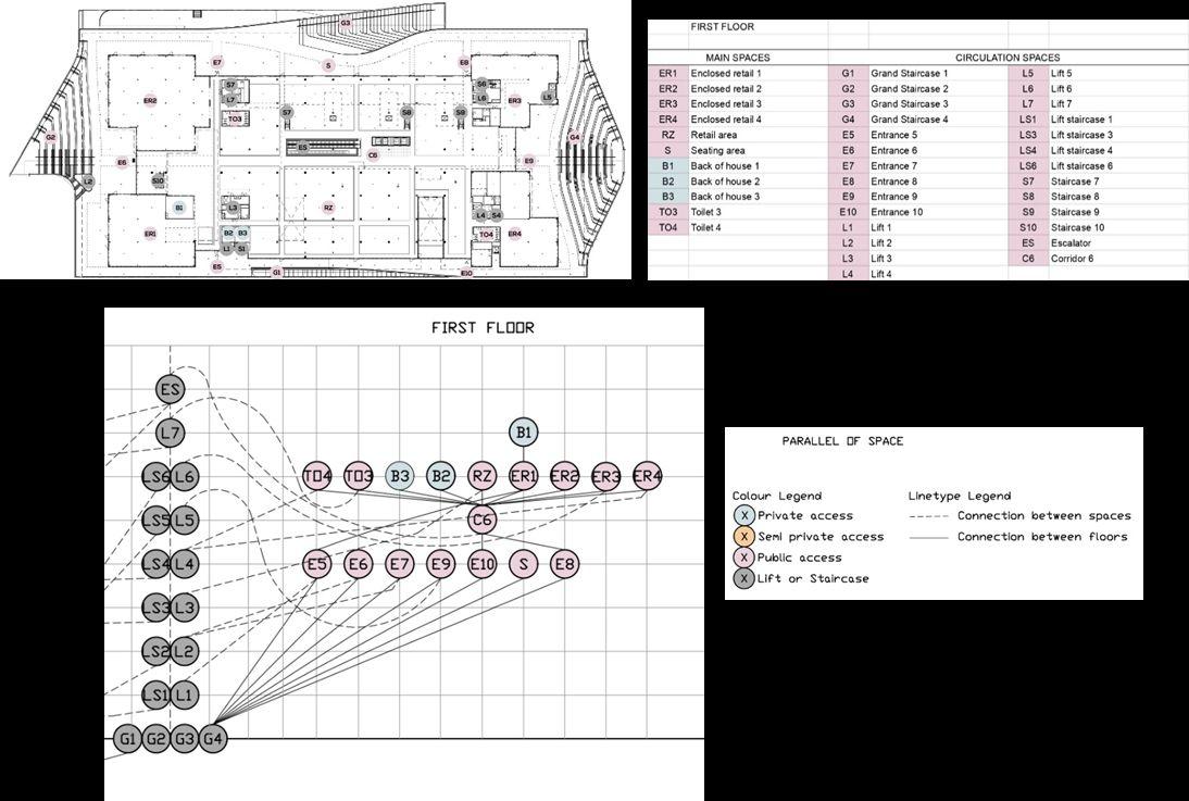
A fish market is a building typology that focuses on catching, repacking, and reselling new edible sea creatures. The building chosen for this case study is the Sydney Fish Market. The case study was selected to be reviewed by a Danish office, 3XN. This project envisions productivity new approach to how a fish market should be. The research methods conducted to study the relation of the space syntax in the New Sydney Fish Market are the Likert Scale and Justified graphs.

26
Site
The case study of Sydney Fish Market appears to exemplify some segregation. It focuses on the geographical arrangement of each user group, ensuring that public and privateaccessisclearlydefined,withlimitedaccesstoremoteusers.Foraneighborhood market, the overall layout of the case study demonstrates a remarkable depth of permeability and navigation. It is particularly beneficial in buildings with a public/private design typology. It is simple and allows general users to move throughout the building spaces without getting lost or having unpleasant experiences due to clear space segregation from street level. The spatial layouts are relatively simple for 70% of private users, such as employees, vendors, and hawkers. Many ground-floor entrances improve navigation and reduce the percentage of crowded places during peak hours. More interaction should be done with the fishermen to enable interaction and increases the productivityofthefishermenandtheeconomy.


27
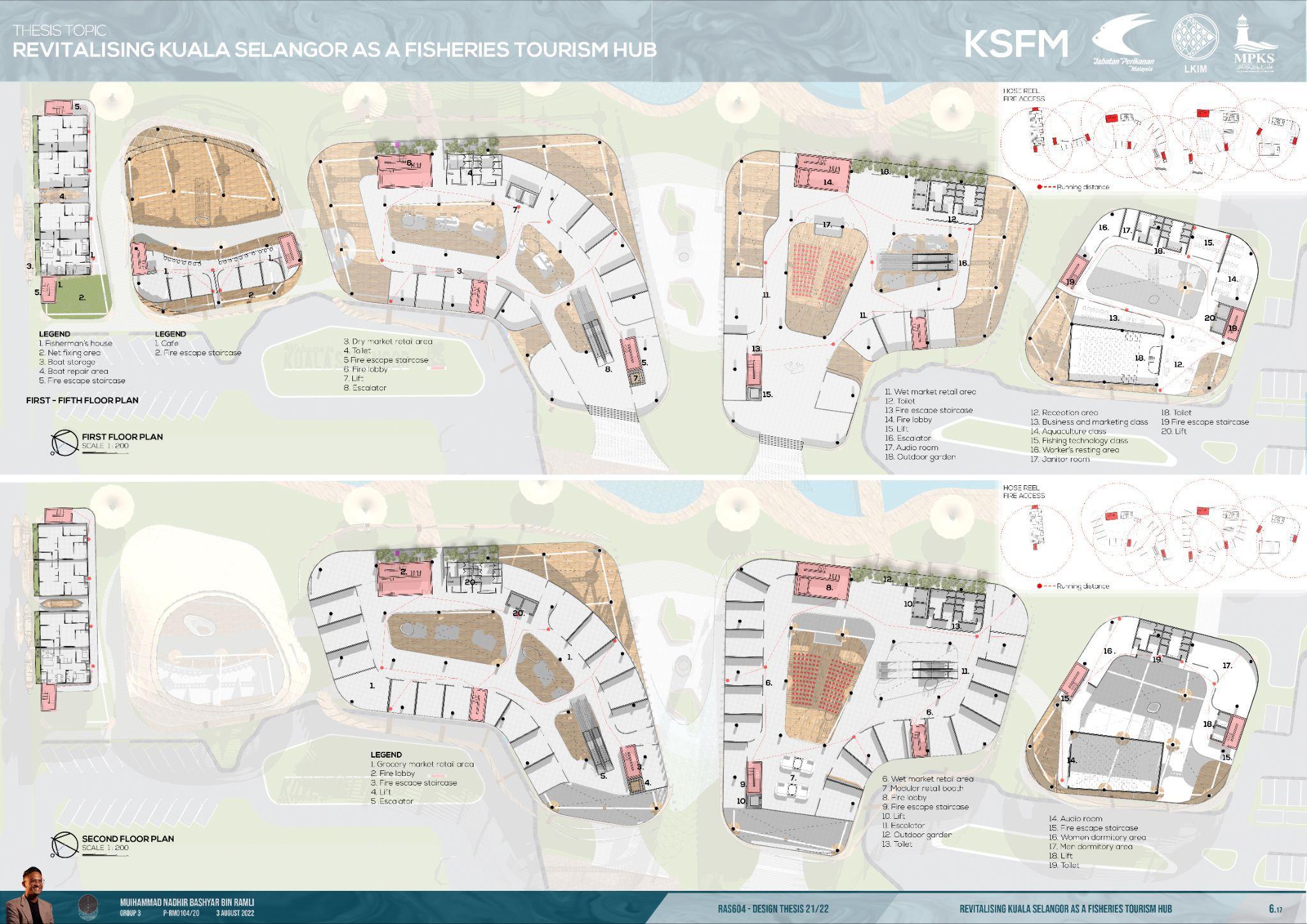
Floor plan and justified graph of Ground Floor level.
Space Syntax Analysis for Site Plan.
First floor plan and justified graph of First Floor level.

30
PASSIVE DESIGN FIRE APPLIANCES ACCESS
BY-LAW 140.

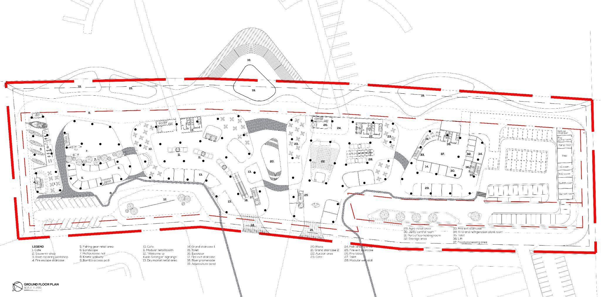
Referring to By-Law 140, in planning the vehicular or appliance access, consideration should be given to the design of the hard standing/ access road in relation to the building with respect to features such as overhangs, canopies, turning radius and other obstructions to the free operation of the firefighting appliances. Location of hydrants must similarly be considered. To close a placement adjacent to the building or beneath an overhang may expose Fire and Rescue personnel to unnecessary risks of worse, render them inoperable in an emergency. Similarly, too close to a location to routes of vehicular traffic may render them susceptible to damage.

2. Overheadclearance:6metres
3. Gradientofaccessway:notexceed1:8.3
FIRE FIGHTING ACCESS WAY
By-law119(1)-Allbuildinginaccessof7000cubicmetresshallabout a street or road or open space of not less than 12 metres width and accessible to fire brigade appliances. The proportion of the building abutting the street, road or open space shall be in accordance with thefollowingdiagrams:
1. Total building volume (total area in sqm x height in m) = 537,956m3
2. Category of building volume in cubic meter for fire appliances access:112,000m3andabove
3.Minimumproportionofperimeterofbuilding:islandsite

Appliances Access FIRE PROTECTION SYSTEM CHAPTER5 MANAGEMENT, PRACTICE AND LAW
Bomba Access Fire
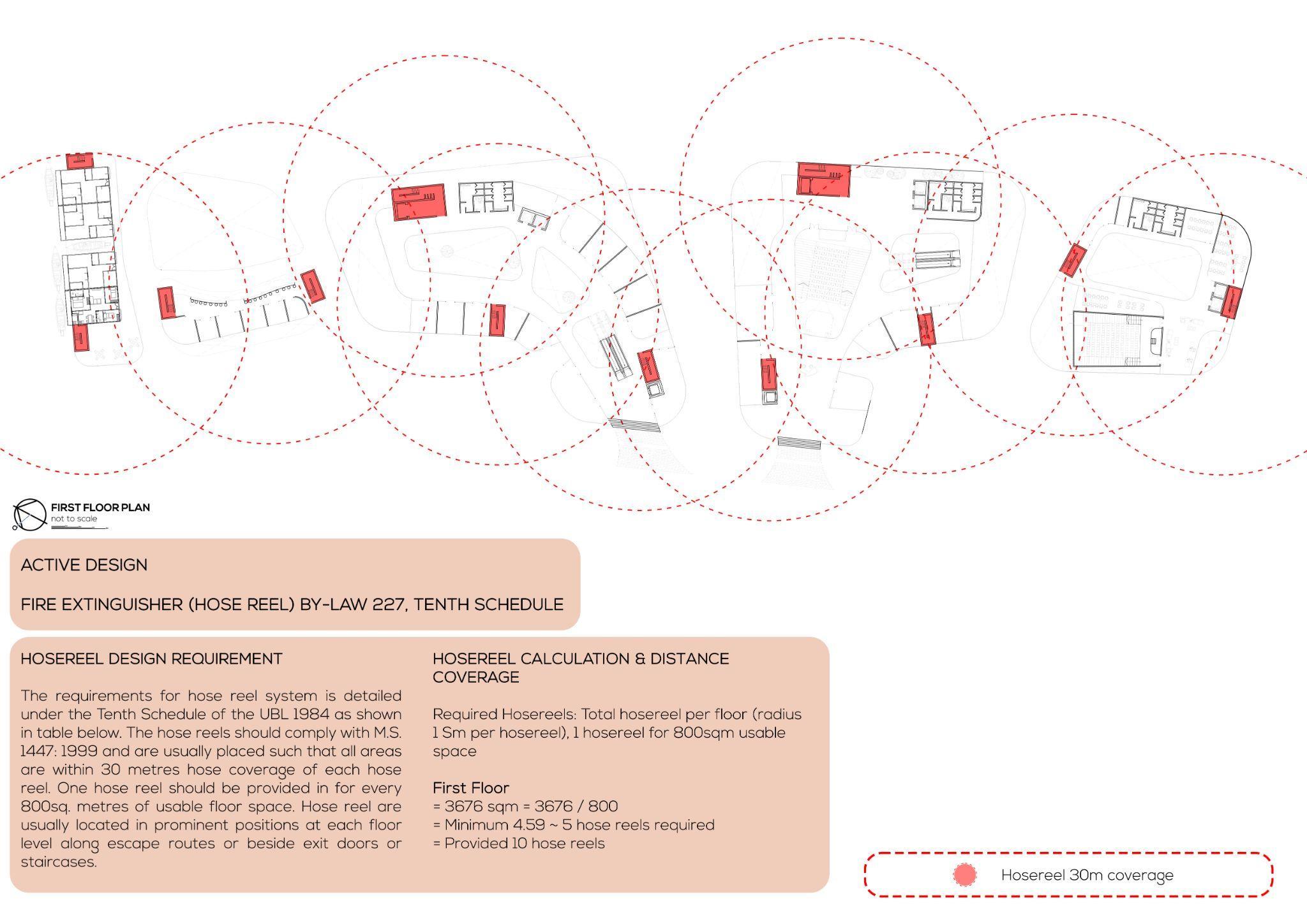
ACTIVE DESIGN : EXTERNAL FIRE HYDRANT (COVERAGE BY-LAW 225)
PASSIVE DESIGN: PLACE OF ASSEMBLY BY-LAW 186, BY-LAW 188, BY-LAW 179
DETECTING AND EXTINGUISHING FIRE
225-(2) Every building shall be served by at least one fire hydrant located not more than 91.5 metres from the nearest point of fire brigade access.
1. Number of External Fire Hydrant Provided: 5 (Lower Ground Level)
Perimeter distance between each External Fire Hydrant: 55-85 metres (Less than 91.5 metres)
2. External Fire Hydrant coverage: 45 metres
3. Hydrant to breeching inlet: 25 metres (less than 30 metres)
4. Distance of each fire external hydrant from building wall: 6 metres
PLACE OF ASSEMBLY (By-Law 186, By-Law 188, By-Law 179)

By- Law 186, Exit doors in places of assembly:
(1) AlI doors used by the public as exit doors from any part of the place of assembly of leading to the open air, shall open only in the direction of exit
(2) in place of assembly all exit doors and doors through which the public pass on the way to open air shall be without locks, bolts or other fastenings while public are in the building Provided that doors used for exit only may be fitted with panic bolts. By-Law 188, travel distance in place of assembly:
(1) Exits in any place of assembly shall be arranged that the travel distance from any point to reach an exit shall not exceed 45 metres for unsprinklered buildings and 60 metres for sprinklered buildings.
1. Number of Place of Assembly provided: 6 at Lower Ground Floor
By-Law 179, Classification of places of assembly- Each place of assembly shall be classified accordingly to its capacity as follows:
1. Class B Capacity (300 to 1000 people) used for the building place of assembly (proposed 700 people)
H H H H H H H
Bomba Access Place of Assembly Hydrant

34
CALCULATION OF OCCUPANT LOAD (By-Law 175, 7th schedule)
Thepurposegroupofthebuildingasshownasfollows:
CALCULATION OF STAIRCASE (By-Law 175) CALCULATION OF STORE EXIT (By-L&w 176)
1. Other Residential
● Largest net floor area = 422 sqm
● Occupancy Load = 24 gross
● No. of person / unit exit = 45 width staircase
● Total exit width = 0.39 unit
● Total exit width = 0.39 unit x 550mm required = 214.91 mm
● Staircase provided = 1100 mm
● Staircase required = 214.91/1100 = 0.20 = 1
● Total staircase required = 1 no. of staircases
● Total staircase provided = 2 no. of staircases
2. Factory
● Largest net floor area = 261.35 sqm
● Occupancy Load = 10 gross
● No. of person / unit exit = 60 width staircase
● Total exit width = 0.44 unit
● Total exit width = 0.44 unit x 550m required = 239.57 mm
● Staircase provided = 1100 mm
COMPUTING STOREY EXIT WIDTHS (By-Law 176)
To compute the required exit width from individual floors of a building:
a. Calculate the floor area net or gross whichever is applicable (net floor area is used).
b. Determine the allowable occupancy load factor as Table (as shown as Table above).
c. Divide the floor area by the number of square metre per person to determine the number of persons for which exits must be provided for that floor (as shown as the in the following calculation).
d. Determine from the table the capacity of the type of exit to be used for the purpose group being designed (as shown as in the following calculation).
e. Calculate the number of units of exit width for each type of exit used based upon the capacity (as shown as the in the following calculation).
● Staircase required = 239.57/1100 = 0.22 = 1
● Total staircase required = 1 no. of staircases
● Total staircase provided = 2 no. of staircases
3. Shop
● Largest net floor area = 2089 sqm
● Occupancy Load = 6 gross
● No. of person / unit exit = 60 width staircase
● Total exit width = 5.8 unit
● Total exit width = 5.8 unit x 550m required = 3190 mm
● Staircase provided = 1100 mm
● Staircase required = 3190/1100 = 2.9 = 3
● Total staircase required = 3 no. of staircases
● Total staircase provided = 3 no. of staircases
SPACE STANDARDS FOR CALCULATION OCCUPANCY LOAD (By-Law 180)
The occupancy load permitted in any place of assembly shall be determined by dividing the net floor area or space assigned to be used by the square metre per occupant as follows
a. Assembly area of concentrated use without fixed seats such as an auditorium, place of worship, dance floor and lodge room- 0.65 square metre per person
b. Assembly area of less concentrated use such as conference room, dining room, drinking establishment, exhibition room, gymnasium, or lounge- 1.35 square meter per person
c. Standing room or waiting space- 3 square metre per person
Purpose Group Occupant load square metre per Capacity Exits No. of persons per unit - Exit Width Doors outside Horizontal Exit Ramp Main Exit Ramp Sec Exit Escalator Stairs Institutional 2 Net 100 100 60 - 60 Other residential 24 Gross 100 60 60 60 45 45 Office 10 Gross 100 100 100 60 60 60 Shop 3 Gross 100 100 100 60 60 60 Factory 10 Gross 100 100 100 60 60 60 Place ofAssembly 1.5 Net 100 100 100 75 75 75
II. Institutional
1. Educational Occupancies
1. (a) 1 or 2 storeys - - -
III. Other residential
2. Hotels and dormitories
(a) (i) Single storey - -
IV. Office
1. 4 storeys and less or less than 1000 sqm gfa
V. Shop
3. 3 storeys and above
(b) 1000 - 3000 sqm
VI. Factory
1. (a) Less than 750 sqm - -

VII. Place ofAssembly Class C (100-300 persons) - -
VIII. Storage and general
3. (a)(ii) 250- 500 sqm
45 Occupancy Hazard (Purpose Group) Extinguishing System Note 2 FireAlarm System Note 3 Emergency Lighting System Note 3
-
-
-
-
G 1 & 2 a
-
-
G 2 -
46

47
CONCLUSION
The goal of fire protection is to save lives, protect property, and save the environment from destruction. Active fire protection systems and passive fire protection systems are the two types of fire protection systems. Simply put, an active fire protection system is a method of fighting fires that employs either manual or automatic fire mechanical systems such as fire alarms, detectors, hose reels, fire telecoms, sprinklers, and others. While passive fire protection systems focus on the combustion and spread of smoke, active fire protection systems protect the escape route to extend the time for evaluation. This system can be implementedbymodifyingarchitecturalelementsanddesignstoincludefireresistancefeatures.
Fire safety and effective fire protection in design in relation to the By-Laws is critical in the practise of architectural career and construction field, as it provides the majority of the necessary and basic knowledge related to the fire fighting by-law and to deal with real life scenario. This knowledge also prepares students for real-world practise in fire fighting design after graduating with a Master of Architecture (Part Il), as a step toward exploring and becoming a professional architect. This knowledge focuses on the requirements for fire fighting design, problem solving for design requirements, implementing creativity in fire fighting design on
50
51 CHAPTER6 CONCLUSION
52
53

54
55
56
57
58
59

60
61
62
63

64
65

66

67