
Fundamentals of Heat and Mass Transfer Bergman
7th Edition Solutions Manual
Full version at: https://testbankbell.com/product/fundamentals-of-heat-and-masstransfer-bergman-7th-edition-solutions-manual/
KNOWN: Thermal conductivity, thickness and temperaturedifference across a sheet of rigid extrudedinsulation.
FIND: (a) The heat flux through a 2 m × 2 m sheet of the insulation, and (b) The heat rate through thesheet
SCHEMATIC:
ASSUMPTIONS: (1) One-dimensionalconduction in thex-direction,(2) Steady-state conditions, (3) Constant properties
ANALYSIS: From Equation 1.2 the heat flux is
PROBLEM 1.2
COMMENTS: (1) Be sure to keep in mind the important distinction between the heat flux (W/m2)and the heat rate (W) (2) The direction of heat flow is from hot to cold. (3) Note that a temperature difference may be expressed in kelvins or degrees Celsius.
PROBLEM 1.3
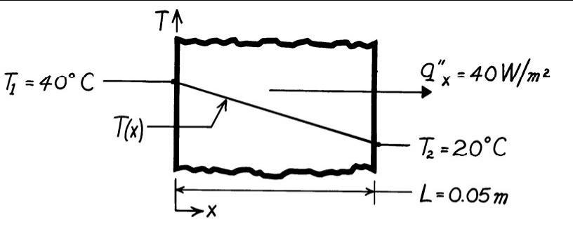
KNOWN: Thicknessand thermal conductivity of a wall. Heat flux applied to one face and temperaturesof both surfaces.
FIND: Whether steady-stateconditionsexist
SCHEMATIC:
ASSUMPTIONS: (1) One-dimensionalconduction,(2) Constantproperties, (3) No internal energy generation.
ANALYSIS: Under steady-stateconditions an energy balance on the control volume shown is
Since the heat flux in at the left face is only 20 W/m2 , the conditions are not steady state <
COMMENTS: If the same heat flux is maintained until steady-stateconditionsare reached, the steady-state temperature difference across the wall will be
which is much smaller than the specified temperature difference of 20°C
PROBLEM 1.3
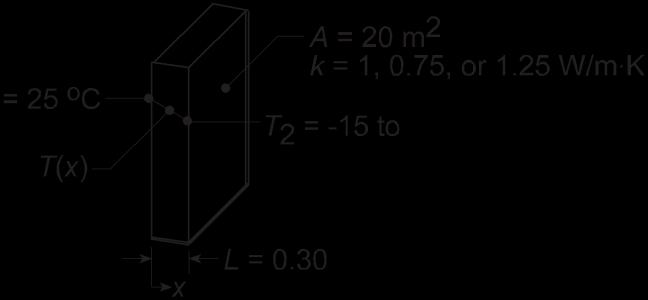
KNOWN: Inner surface temperature and thermal conductivityof a concrete wall.
FIND: Heat loss by conduction through the wall as a function of outer surface temperaturesranging from -15 to 38°C.
SCHEMATIC:
ASSUMPTIONS: (1) One-dimensionalconduction in the x-direction,(2) Steady-state conditions,(3) Constant properties.
ANALYSIS: From Fourier’s law, if q ′ x ′ and k are each constant it is evident that the gradient, dT dx = q ′ x ′ k , is a constant, and hence the temperaturedistribution is linear The heat flux must be constant under one-dimensional,steady-stateconditions;and k is approximately constant if it depends only weakly on temperature. The heat flux and heat rate when the outside wall temperatureis T2 = -15°C are
CombiningEqs. (1) and (2), the heat rate qx can be determinedfor the range of outer surface temperature, -15 ≤ T2 ≤ 38°C, with different wall thermal conductivities, k.
K, the heat loss varies linearly from +2667 W to -867 W and is zero when the inside and outer surface temperatures are the same The magnitude of the heat rate increases with increasing thermal conductivity
For the concrete wall, k = 1 W/m
COMMENTS: Without steady-state conditions and constant k, the temperature distribution in a plane wall would not be linear
PROBLEM 1.4
KNOWN: Dimensions, thermal conductivityand surface temperatures of a concrete slab. Efficiency of gas furnace and cost of natural gas
FIND: Daily cost of heat loss.
SCHEMATIC:
ASSUMPTIONS: (1) Steady state, (2) One-dimensionalconduction,(3) Constant properties. ANALYSIS: The rate of heat loss by conductionthrough the slab is q =k (LW)T1 T2 =1.4W/ m⋅K(11m×8m) 7°C =4312 W < t 0.20m
The daily cost of natural gas that must be combusted to compensatefor the heat loss is = qCg 4312W×$0.02/ MJ Cd = (Δt)= (24h/d ×3600s/h)=$8.28/d <
ηf 0.9×10⁶J/MJ
COMMENTS: The loss could be reduced by installing a floor covering with a layer of insulation between it and the concrete.
PROBLEM 1.5
KNOWN: Thermal conductivityand thicknessof a wall. Heat flux through wall. Steady-state conditions
FIND: Value of temperature gradient in K/m and in °C/m
SCHEMATIC:
10 W/m2
= 2 3 W/m·K
ASSUMPTIONS: (1) One-dimensionalconduction,(2) Constant properties.
ANALYSIS: Under steady-stateconditions, dT q " 10 W/m2 = x = = 4.35 K/m = 4.35 °C/m < dx k 2.3 W/m K
Since the K units here represent a temperature difference, and since the temperaturedifference is the same in K and °C units, the temperaturegradient value is the same in either units.
COMMENTS: A negative value of temperaturegradient means that temperatureis decreasing with increasing x,corresponding to a positive heat flux in the x-direction.
PROBLEM 1.6
KNOWN: Heat flux and surface temperaturesassociatedwith a wood slab of prescribed thickness.
FIND: Thermal conductivity, k, of the wood.
SCHEMATIC:
ASSUMPTIONS: (1) One-dimensionalconductionin the x-direction, (2) Steady-state conditions, (3) Constant properties.
ANALYSIS: Subject to the foregoing assumptions,the thermal conductivity may be determinedfrom Fourier’s law, Eq. 1.2. Rearranging,
COMMENTS: Note that the °C or K temperature units may be used interchangeablywhen evaluating a temperature difference.
PROBLEM 1.7
KNOWN: Inner and outer surface temperatures of a glass window of prescribeddimensions.
FIND: Heat loss through window
SCHEMATIC:
ASSUMPTIONS: (1) One-dimensionalconductionin the x-direction, (2) Steady-state conditions, (3) Constant properties
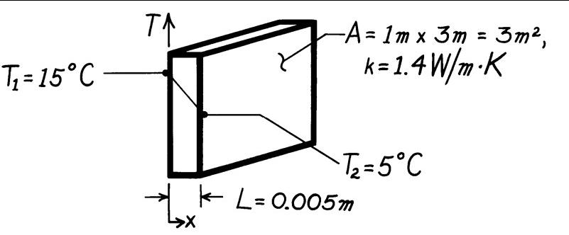
ANALYSIS: Subject to the foregoing conditions the heat flux may be computed from Fourier’s law, Eq. 1.2.
qx ′ =k T1 T2 L
W (15-5)oC
q ′ x ′ =1.4 m⋅K 0.005m
q ′ x ′ =2800 W/m2 .
Since the heat flux is uniform over the surface, the heat loss (rate) is
q = q ′ x ′ ×A
q = 2800 W/ m 2 × 3m2
q = 8400 W. <
COMMENTS: A linear temperaturedistribution exists in the glass for the prescribed conditions
PROBLEM 1.8
KNOWN: Net power output, average compressorand turbine temperatures, shaft dimensionsand thermal conductivity
FIND: (a) Comparisonof the conduction rate through the shaft to the predicted net power output of the device, (b) Plot of the ratio of the shaft conductionheat rate to the anticipated net power output of the device over the range 0.005 m ≤ L≤ 1 m and feasibilityof a L= 0.005 m device.
SCHEMATIC:
ASSUMPTIONS: (1) Steady-stateconditions,(2) Constant properties,(3) Net power output is proportional to the volumeof the gas turbine
PROPERTIES: Shaft (given): k= 40 W/m K.
ANALYSIS: (a) The conductionthrough the shaft may be evaluated using Fourier’s law, yielding
The ratio of the conductionheat rate to the net power output is
(b) The volume of the turbine is proportional to L3 .Designating La = 1 m, da = 70 mm and Pa as the shaft length, shaft diameter, and net power output, respectively, in part (a),
and the ratio of the conduction heat rate to the net power output is
PROBLEM 1.8 (Cont.)
The ratio of the shaft conduction to net power is shown below. At L= 0.005 m = 5 mm, the shaft conductionto net power output ratio is 0 74. The concept of the very small turbine is not feasible since it will be unlikely that the large temperaturedifference between the compressor and turbine can be maintained <
COMMENTS: (1) The thermodynamicsanalysis does not account for heat transfer effects and is therefore meaningful onlywhen heat transfer can be safely ignored, as is the case for the shaft in part (a). (2) Successful miniaturizationof thermal devices is often hindered by heat transfer effects that must be overcome with innovative design.
PROBLEM 1.9
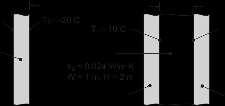
KNOWN: Width, height, thickness and thermal conductivity of a single pane window and the air space of a double pane window. Representativewinter surface temperatures of single pane and air space.
FIND: Heat loss through single and double pane windows.
SCHEMATIC:
ASSUMPTIONS: (1) One-dimensionalconductionthrough glass or air, (2) Steady-state conditions, (3) Enclosed air of double pane window is stagnant (negligible buoyancy induced motion).
ANALYSIS: From Fourier’s law, the heat losses are
COMMENTS: Losses associated with a single pane are unacceptableand would remain excessive, even if the thickness of the glass were doubled to match that of the air space. The principal advantageof the double pane construction resides with the low thermal conductivity of air (~ 60 times smaller than that of glass). For a fixed ambient outside air temperature, use of the double pane construction would also increase the surface temperature of the glass exposed to the room (inside) air.
PROBLEM 1.10
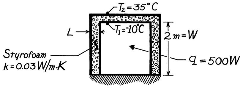
KNOWN: Dimensions of freezer compartment Inner and outer surface temperatures.
FIND: Thickness of styrofoam insulation needed to maintainheat load below prescribed value.
SCHEMATIC:
ASSUMPTIONS: (1) Perfectly insulated bottom, (2) One-dimensionalconductionthrough 5 walls of area A = 4m 2 (3) Steady-stateconditions, (4) Constant properties.
ANALYSIS: Using Fourier’s law, Eq. 1.2, the heat rate is q = q ′′ ⋅A = k ΔT A L total
Solving for L and recognizing that Atotal = 5× 2 , find
COMMENTS: The corners will cause local departures fromone-dimensionalconduction and a slightly larger heat loss.
PROBLEM 1.11

KNOWN: Heat flux at one face and air temperature and convectioncoefficient at other face of plane wall. Temperatureof surface exposed to convection.
FIND: If steady-stateconditions exist If not, whether the temperatureis increasing or decreasing
ASSUMPTIONS: (1) One-dimensionalconduction,(2) No internal energy generation.
Conservationof energy for a control volume around the wall gives
Since dEst/dt ≠ 0, the system is not at steady-state. <
Since dEst/dt < 0, the stored energy is decreasing,therefore the wall temperatureis decreasing. <
COMMENTS: When the surface temperature of the face exposed to convectioncools to 31°C, qin = qout and dEst/dt = 0 and the wall will have reached steady-state conditions.
PROBLEM 1.12
KNOWN: Dimensions and thermal conductivityof food/beveragecontainer. Inner and outer surface temperatures
FIND: Heat flux through container wall and total heat load
SCHEMATIC:
ASSUMPTIONS: (1) Steady-state conditions, (2) Negligible heat transfer through bottom wall, (3) Uniform surface temperatures and one-dimensional conduction through remaining walls.
ANALYSIS: From Fourier’s law, Eq 1.2, the heat flux is
Since the flux is uniform over each of the five walls through which heat is transferred,the heat load is
COMMENTS: The corners and edges of the container create local departuresfrom onedimensional conduction, which increase the heat load. However, for H, W1,W2 >> L, the effect is negligible.
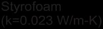
PROBLEM 1.13
KNOWN: Masonry wall of known thermal conductivity has a heat rate which is 80% of that through a compositewall of prescribed thermal conductivityand thickness.
FIND: Thickness of masonry wall
SCHEMATIC:
ASSUMPTIONS: (1) Both walls subjected to same surface temperatures, (2) Onedimensionalconduction, (3) Steady-state conditions, (4) Constant properties.
ANALYSIS: For steady-stateconditions, the conductionheat flux through a onedimensionalwall follows from Fourier’s law, Eq. 1 2,
where ΔT represents the differencein surface temperatures Since ΔT is the same for both walls, it follows that
COMMENTS: Not knowing the temperature differenceacross the walls, we cannot find the value of the heat rate.
PROBLEM 1.14
KNOWN: Expressionfor variable thermal conductivity of a wall Constant heat flux Temperatureat x = 0
FIND: Expressionfor temperaturegradient and temperaturedistribution.
SCHEMATIC:
ASSUMPTIONS: (1) One-dimensionalconduction.
ANALYSIS: The heat flux is given by Fourier’s law, and is known to be constant, therefore
Solving for the temperaturegradient and substituting the expression for k yields
This expression can be integrated to find the temperature distribution, as follows:
Since q ′ x ′ =constant , we can integrate the right hand side to find
where c is a constant of integration. Applying the known conditionthat T = T1 at x = 0, we can solve for c
Therefore, the temperaturedistributionis given by
COMMENTS: Temperaturedistributionsare not linear in many situations, such as when the thermal conductivityvaries spatially or is a function of temperature Non-lineartemperature distributions may also evolve if internal energygeneration occurs or non-steadyconditions exist
PROBLEM 1.15
KNOWN: Thickness, diameter and inner surface temperatureof bottom of pan used to boil water Rate of heat transfer to the pan.
FIND: Outer surface temperatureof pan for an aluminum and a copper bottom.
SCHEMATIC:
ASSUMPTIONS: (1) One-dimensional,steady-stateconductionthrough bottomof pan.
ANALYSIS: From Fourier’s law, the rate of heat transferby conductionthrough the bottom of thepan is
Aluminum: T1 =110 oC+
Copper: T1 =110 oC+
COMMENTS: Although the temperaturedrop across the bottom is slightly larger for aluminum (due to its smaller thermal conductivity),it is sufficientlysmall to be negligiblefor both materials. To a good approximation,the bottom may be considered isothermal at T ≈ 110 °C, which is a desirable feature of pots and pans.

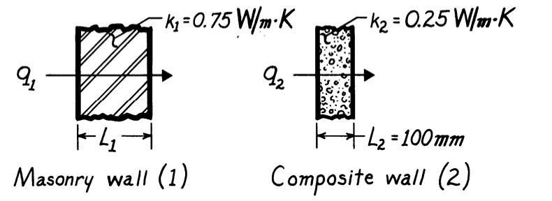
PROBLEM 1.16
KNOWN: Dimensions and thermal conductivity of a chip. Power dissipated on one surface
FIND: Temperaturedrop across the chip.
SCHEMATIC:
ASSUMPTIONS: (1) Steady-stateconditions, (2) Constant properties, (3) Uniform heat dissipation, (4) Negligibleheat loss from back and sides, (5) One-dimensionalconduction in chip.
ANALYSIS: All of the electrical power dissipated at the back surface of the chip is transferred by conductionthrough the chip. Hence, from Fourier’s law,
COMMENTS: For fixed P, the temperaturedrop across the chip decreases with increasing k and W, as well as with decreasing t.
PROBLEM 1.17
KNOWN: Heat flux and convectionheat transfer coefficient for boiling water Saturation temperature and convectionheat transfer coefficient for boiling dielectricfluid.
FIND: Upper surface temperatureof plate when water is boiling Whether plan for minimizing surface temperatureby using dielectricfluid will work.
SCHEMATIC:
ASSUMPTIONS: Steady-stateconditions
PROPERTIES: Tsat,w = 100°C at p = 1 atm
ANALYSIS: Accordingto the problem statement, Newton’s law of cooling can be expressed for a boiling processas

Thus,
When the fluid is water,
When the dielectric fluid is used,
Thus, the technician’sproposedapproach will not reduce the surface temperature <
COMMENTS: (1) Even though the dielectricfluid has a lower saturation temperature,this is more than offset by the lower heat transfer coefficient associated with the dielectric fluid. The surface temperature with the dielectric coolant exceeds the melting temperatureof many metals such as aluminum and aluminumalloys (2) Dielectric fluids are, however, employed inapplications such as immersioncoolingof electronic components,where an electrically-conductingfluid such as water could not be used.
PROBLEM 1.18
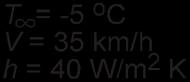
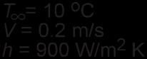
KNOWN: Hand experiencingconvection heat transfer with moving air and water.
FIND: Determine which conditionfeels colder. Contrast these results with a heat loss of 30 W/m2 under normal room conditions.
SCHEMATIC:
ASSUMPTIONS: (1) Temperatureis uniform over the hand’s surface, (2) Convectioncoefficient is uniformover the hand, and (3) Negligibleradiation exchange between hand and surroundingsin the case of air flow
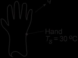
ANALYSIS: The hand will feel colder for the conditionwhich results in the larger heat loss. The heat loss can be determinedfrom Newton’slaw of cooling, Eq. 1.3a, written as
COMMENTS: The heat loss for the hand in the water stream is an order of magnitude larger than when in the air streamfor the given temperature and convectioncoefficientconditions. In contrast, the heat loss in a normal room environment is only 30 W/m2 which is a factor of 400 times less than the loss in the air stream In the room environment,the hand would feel comfortable; in the air and water streams, as you probably know from experience, the hand would feel uncomfortablycold since the heat loss is excessively high.