7 minute read
Production Testing of MEMS & Sensors

Vineet Pancholi, Senior Director, Test technology Amkor Technology, Inc.
Abstract
The number and variety of sensors in typical mobile, wearable and automotive applications has exploded in the recent past and continues to grow well into the future. It is mission critical in select customer applications to ensure each of these sensors are production tested prior to assembly into the customer platform. Production testing of sensors requires the handler to induce the accurate level of stimulus in the range of operation and test access with tester instruments to test against the data sheet specifications. This article describes the production test challenges for high volume manufacturing.
Keywords
Semiconductor, Outsourced Semiconductor Assembly & Test (OSAT), Multidie Packages, Heterogeneous Integration (HI) [1], Test, Functional Test, Structural Test, System Level Test (SLT), MicroElectro-Mechanical Systems (MEMS), Production Test Flow.
I. Introduction
Amkor delivers packaging and test services [2] for sensors and MEMS devices for magnetometers, accelerometers, gyroscopes, microphones, pressure, inertial, optical and RF (Radio Frequency) applications. Each of these sensor types may have a specific range of operation. For instance, absolute pressure sensors, side crash detection sensors, tire pressure sensors and barometric pressure sensors may be different sensors designed for the specific range of operation.
Temperature, pressure, and microphone sensor types may be amongst the highest by production volumes that have an automotive & environmental attach rate. There are a variety of test challenges for these products in the high-volume manufacturing process. The objective of this article is to highlight a couple of important aspects that are being resolved by the test industry and Amkor, in order to reduce the overall production cycle times and hence the cost.
The RF sensors are a different category of product. RF sensors depend on RADAR (radio detection and ranging). In an automotive application the transmitter transmits an RF pulse, which when reflected back from a reflector and received at the receiver is used to com- pute the distance between two automobiles.
II. Multi-Die Package
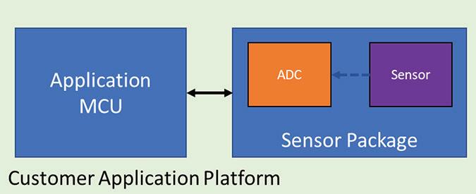
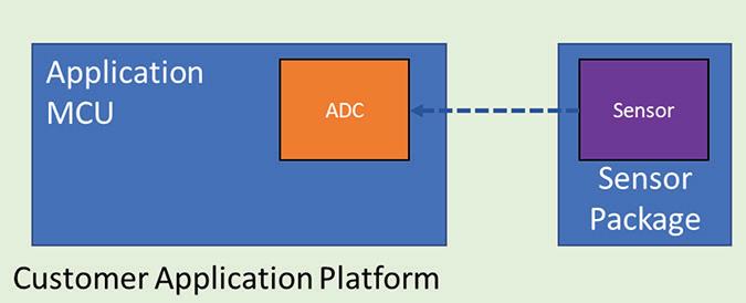
For traditional customer applications, sensors are typically packaged separately. There are several benefits to the approach in the end application. The larger application platform may communicate with the sensor, via an application specific integrated controller (ASIC) over a slow speed serial digital interface like I2C, SPI, UART and/or others. There are two different functional block types within the package, one that includes an analog functional block and the other that includes a controller in addition within the package. Figures 1 & 2 show the two different sensor package blocks.
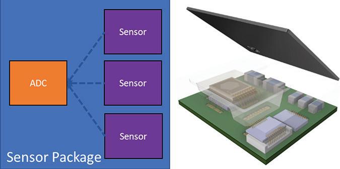
More recent application architectures and designs require higher density integration and hence demanding multiple sensors [2, 3] getting integrated within a single package. Figure 3 shows a block diagram on the left and a package model on the right. Heterogeneous Integration Roadmap chapter 17 [6] does a good job describing the challenges associated with multi-sensor product testing.
Depending on the sensor type and the end application, the sensor package may include a window to expose the sensor die, or be over-molded or have a cavity or may have a need to be a combination of molded and cavity type. These are pictured in Figure 4.
III. Key Test Challenges
One of the vital production test steps in the manufacturing process, is the Final Test step.
Production testing of sensor DUTs (Device Under Test) requires an ATE (Automatic Test Equipment), material handler and the test interface hardware. Figure 5 shows the functional block depiction of the production test cell. The package handler includes a calibrated stimulus source. This source generates the stimulus that the DUT is subjected to. The ATE is electrically connected to the DUT, via the test hardware and tests for all required data sheet attributes.
Product affordability & costing targets mandate multi-site testing of sensors. The magnitude of parallelism is limited by the maximum allowable parts that can be physically located on the test hardware, stimulus constraints and the number of parts the handler is able to present at the test sites.
The tester resource requirements to test most sensor types includes the appropriate count of channels on the power supply, digital & clock channels and analog test channels. (see Figure 6)
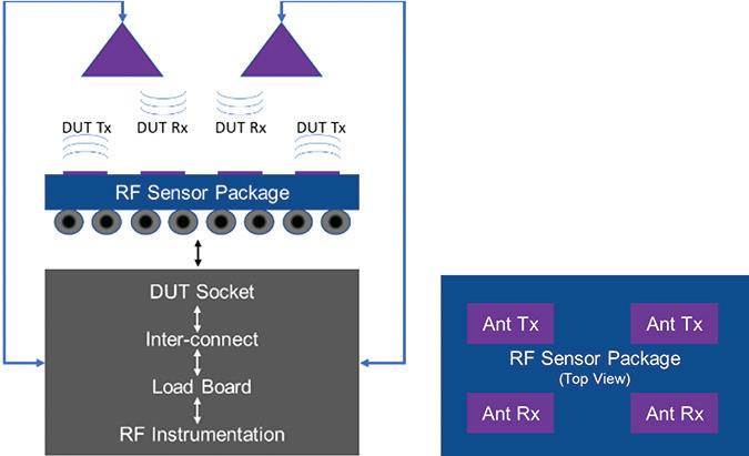
RF sensors are different. RF sen- sor test requires RF instrumentation within the ATE. These radar sensors may include an antenna that may be integrated within the package. The CW (continuous wave) frequencies may range from <10GHz to <100GHz and signal power
<+10dBm, depending on the end-application requirements.
Testing of RF sensors is challenging, from a DUT setup standpoint. The twoway RF signal path between the test head and the DUT is made up of conduction path medium that may include shielded cables and the lossy over the “air” medium. Production setup must be repeatable and reproducible and calibratable. Any deviations from acceptable limits may result in loss of yield.
While multi-sensor packages, like the ones outlined in Figure 3, result in higher levels of integration, they may result in increased test times per insertion or increased count of test insertions to test each sensor, which again results in increased test time and hence the cost. Examples of multi-sensor packages include pressure/temperature, microphone/temperature or humidity/temperature.
The most popular and demanding market segment with the most stringent test requirements is the automotive market [4, 5]. The automotive industry, as of the writing of this article, is driving the most complex packaging and test services.
IV. Package Handling Challenges
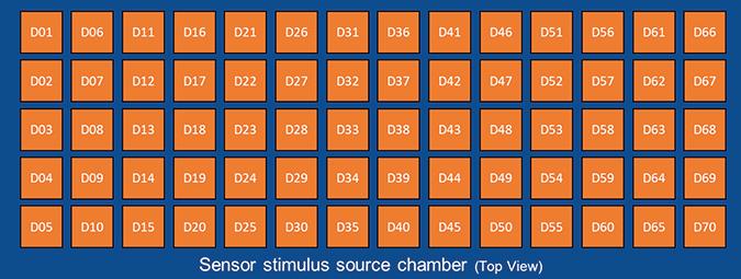
Test capabilities for temperature sensors is by far relatively easily implemented in production test. Package handler manufacturers have stimulus sources integrated with package handling equipment. The number of choices of these stimulus sources is large and mostly customized by the handler supplier for each type of sensor. Sensors for microphone, magnetometer, accelerometer, pressure, relative humidity, gas detectors, and others may require test signal isolation from the production environment. At the same time, product affordability warrants maximizing parallel testing. Figure 8 shows an example of 70 sensor placement topology being tested in parallel within a production material handler.
Product specific parallel site test hardware design including DUT sockets, may require careful design verification to ensure all sites are stimulated within the specified test limits.
Microphone testing may be sensitive to stray ambient (e.g. facility ventilation air ducts) sound sources. There are numerous stray sound sources within the production test environment that may impact the test result and production yield. In addition to isolation of stray sources of sounds, the manufacturing test cell may be sensitive to motor vibrations, floor footing vibrations, and changes in light sources, etc. Test equipment motors may need to be paused for the duration of test, which may impact the overall production throughput. Vacuum cups on the plungers to pick and place DUTs into test sites requires careful design, to avoid damaging the unit. Mechanical handling of pick and place or bowl feeder handlers is designed to prevent dropping of device packages. Dropped packages result in loss of manufacturing yield. Production site facility requirements are stringent. Production yields may be sensitive to variation in test facility temperature and relative humidity during the day and night. In order to alleviate some of the above stated challenges, handler vendors have encapsulated microphone test stimulus within an isolation chamber. The shield design isolates the DUTs from getting impacted for the duration of testing. Stimulus reference sound source and reference microphone may require periodic calibration, depending on the production environment to ensure impairment free operation.
Pressure sensor testing, depending on the range of operation, may be sensitive to minor leaks within the test chamber of the handler. The handler pressure chamber is designed to maintain, pressure, temperature, and relative humidity within the allowable specification limits. Cycling production parts through the chamber may result in condensation. This may result in additional settling times that slow down production throughput.
Sensors may require per unit trimming at a specific temperature and relative humidity, to ensure accuracy to the product data sheet. The trimming process may or may not be completely automated and while trimming necessary to perform, it may take time, that reduces the production units per hour (UPH) metric.
Other MEMS and sensors may have their own set of non-idealities within the handler and stimulus chamber. Multisensor products have continued to add complexities to the production test processes and systems. MEMS and sensor production test equipment may benefit from ‘design for manufacturing’ systemic and design improvements, that will allow production sites to keep the overall manufacturing costs from increasing as the sensor product volumes grow in the future.
MEMS and sensors in all categories may require multiple test insertions to test the performance at the complete temperature range of operation. Automotive range of operation may be wide.
Higher the site parallelism, higher are the sources of errors that impact the overall production throughput. It takes time and effort to eliminate test equipment induced false failures, to optimize first pass yield. Re-test of sensors may be required, to keep test equipment induced failures in-check. Methods to isolate true sensor architecture, design, fabrication, and package assembly related failures are required to be accurately tagged to allow process improvements generation over generation.
V. Test Manufacturing Metrics
There are a variety of key process indicators (KPI) that are tracked to ensure that test factory efficiencies are at the optimal levels and the out-going quality metrics for sensor production test are met. Typical factory throughput indicators may include Units per Hour (UPH), Units per Month (UPM), test cell count, lot rejection rate (LRR), first pass yield (FPY), on-time delivery (OTD), customer returns, inspection failures, and others.
Apart from sensor architecture, design, fabrication and packaging related failure mechanisms (true failures), inefficiencies that result in less-than-optimal yield for sensor production testing primarily stem from consistent performance on all parallel sites within the test cell. The central reason for site failure may be test hardware (load-board) related or inconsistent performance of the stimulus. It may be important to track the aging of production test hardware, to ensure that these fail mechanisms are minimized or eliminated with systemic root cause fixes.
VI. Summary
The number of sensors in recent applications is rapidly growing. IOT,